EP2338650A2 - Power tool storage case - Google Patents
Power tool storage case Download PDFInfo
- Publication number
- EP2338650A2 EP2338650A2 EP10195658A EP10195658A EP2338650A2 EP 2338650 A2 EP2338650 A2 EP 2338650A2 EP 10195658 A EP10195658 A EP 10195658A EP 10195658 A EP10195658 A EP 10195658A EP 2338650 A2 EP2338650 A2 EP 2338650A2
- Authority
- EP
- European Patent Office
- Prior art keywords
- power tool
- storage case
- lid
- locking plate
- locking
- Prior art date
- Legal status (The legal status is an assumption and is not a legal conclusion. Google has not performed a legal analysis and makes no representation as to the accuracy of the status listed.)
- Granted
Links
- 238000005192 partition Methods 0.000 claims description 4
- 238000009751 slip forming Methods 0.000 claims description 2
- 230000001419 dependent effect Effects 0.000 claims 1
- 230000000694 effects Effects 0.000 description 6
- 230000007246 mechanism Effects 0.000 description 5
- 238000012986 modification Methods 0.000 description 3
- 230000004048 modification Effects 0.000 description 3
- 238000000638 solvent extraction Methods 0.000 description 3
- 238000013459 approach Methods 0.000 description 2
- 238000000034 method Methods 0.000 description 2
- 230000008569 process Effects 0.000 description 2
- 230000009471 action Effects 0.000 description 1
- 238000005452 bending Methods 0.000 description 1
- 230000003247 decreasing effect Effects 0.000 description 1
- 230000005484 gravity Effects 0.000 description 1
- 229920005989 resin Polymers 0.000 description 1
- 239000011347 resin Substances 0.000 description 1
- 230000000717 retained effect Effects 0.000 description 1
- 229920003002 synthetic resin Polymers 0.000 description 1
- 239000000057 synthetic resin Substances 0.000 description 1
Images


Classifications
-
- B—PERFORMING OPERATIONS; TRANSPORTING
- B25—HAND TOOLS; PORTABLE POWER-DRIVEN TOOLS; MANIPULATORS
- B25H—WORKSHOP EQUIPMENT, e.g. FOR MARKING-OUT WORK; STORAGE MEANS FOR WORKSHOPS
- B25H3/00—Storage means or arrangements for workshops facilitating access to, or handling of, work tools or instruments
- B25H3/02—Boxes
- B25H3/021—Boxes comprising a number of connected storage elements
- B25H3/023—Boxes comprising a number of connected storage elements movable relative to one another for access to their interiors
-
- E—FIXED CONSTRUCTIONS
- E05—LOCKS; KEYS; WINDOW OR DOOR FITTINGS; SAFES
- E05B—LOCKS; ACCESSORIES THEREFOR; HANDCUFFS
- E05B65/00—Locks or fastenings for special use
- E05B65/52—Other locks for chests, boxes, trunks, baskets, travelling bags, or the like
- E05B65/5207—Other locks for chests, boxes, trunks, baskets, travelling bags, or the like characterised by bolt movement
- E05B65/5246—Other locks for chests, boxes, trunks, baskets, travelling bags, or the like characterised by bolt movement rotating
- E05B65/5269—Other locks for chests, boxes, trunks, baskets, travelling bags, or the like characterised by bolt movement rotating about an axis parallel to the surface on which the lock is mounted
- E05B65/5276—Other locks for chests, boxes, trunks, baskets, travelling bags, or the like characterised by bolt movement rotating about an axis parallel to the surface on which the lock is mounted parallel to the wing edge
-
- E—FIXED CONSTRUCTIONS
- E05—LOCKS; KEYS; WINDOW OR DOOR FITTINGS; SAFES
- E05C—BOLTS OR FASTENING DEVICES FOR WINGS, SPECIALLY FOR DOORS OR WINDOWS
- E05C19/00—Other devices specially designed for securing wings, e.g. with suction cups
- E05C19/10—Hook fastenings; Fastenings in which a link engages a fixed hook-like member
- E05C19/12—Hook fastenings; Fastenings in which a link engages a fixed hook-like member pivotally mounted around an axis
- E05C19/14—Hook fastenings; Fastenings in which a link engages a fixed hook-like member pivotally mounted around an axis with toggle action
-
- E—FIXED CONSTRUCTIONS
- E05—LOCKS; KEYS; WINDOW OR DOOR FITTINGS; SAFES
- E05C—BOLTS OR FASTENING DEVICES FOR WINGS, SPECIALLY FOR DOORS OR WINDOWS
- E05C3/00—Fastening devices with bolts moving pivotally or rotatively
- E05C3/02—Fastening devices with bolts moving pivotally or rotatively without latching action
- E05C3/04—Fastening devices with bolts moving pivotally or rotatively without latching action with operating handle or equivalent member rigid with the bolt
- E05C3/047—Fastening devices with bolts moving pivotally or rotatively without latching action with operating handle or equivalent member rigid with the bolt rotating about an axis parallel to the surface on which the fastener is mounted
- E05C3/048—Fastening devices with bolts moving pivotally or rotatively without latching action with operating handle or equivalent member rigid with the bolt rotating about an axis parallel to the surface on which the fastener is mounted parallel to the wing edge
Definitions
- the present invention relates to a power tool storage case for storing an electric power tool such as an impact driver and its accessories.
- a power tool storage case including a storage case in the shape of an open rectangular box and configured to store an electric power tool body, a lid case having a shape similar to that of the storage case, fixing latches capable of locking the storage case and the lid case together, a sub-storage portion provided at an outer surface of the lid case and configured to store small pieces including bits, and a hingedly connected cover (outer lid) for opening or closing the sub-storage portion.
- the cover can be locked by a fixing latch.
- the above conventional power tool storage case employs a so-called toggle latch comprising an engagement member and an urging member.
- toggle latch comprising an engagement member and an urging member.
- a power tool storage case for storing an electric power tool comprises: a main body casing having a storage portion configured to store an electric power tool; a lid member hingedly connected to the main body casing and capable of opening or closing the storage portion; a sub-storage portion provided at an outer surface of the lid member; and an outer lid hingedly connected to the lid member and capable of opening or closing the sub-storage portion.
- a locking portion is provided on the outer lid so that when the sub-storage portion is closed by the outer lid, the locking portion is moved to an engagement position at which the locking portion is engaged with an engageable portion provided on the lid member, and the locking portion is movable from the engagement position to a disengagement position at which the locking portion is disengaged from the engageable portion.
- the power tool storage case according to the first aspect may further comprise an urging means for urging the locking portion toward the engagement position.
- the power tool storage case according to the first aspect or the second aspect may be characterized in that the locking portion comprises a locking plate separately provided on the outer lid.
- the power tool storage case according to any one of the first to third aspect may be characterized in that the locking portion is provided to be flush with or dented inward from an outer surface of the outer lid.
- the power tool storage case according to any one of the first to fourth aspect may be characterized in that each of the main body casing and the lid member is shaped like an open rectangular box, and the main body casing and the lid member are hingedly connected at their rear surfaces, which define a rear surface of the power tool storage case, whereas front surfaces of the main body casing and the lid member are locked or unlocked by a pair of latches, and in that the sub-storage portion and the outer lid having the locking portion are disposed at an upper surface of the lid member.
- the power tool storage case according to the fifth aspect may be characterized in that a handle is provided in a right-and-left direction at a front surface of the power tool storage case, and in that a partition projection which is parallel to the handle is provided between the locking portion and the handle on one of the lid member and the outer lid.
- a pair of right and left projections may be provided at the front surface of the power tool storage case in such a manner as to protrude frontward from the latches held in a locked state, and both ends of the handle may be rotatably connected to the pair of right and left projections.
- the pair of right and left projections may be continuously formed at both end portions of the partition projection.
- the power tool storage case may be characterized in that the locking plate is supported in a window or a cutout formed in the outer lid and rotatable around an axis parallel to that of a hinge of the lid member.
- a plate-like stopper strip having a barb is provided at its lower end is provided on and protrudes downward from a lower surface of the locking plate and a stopper projection engageable with the barb of the stopper strip is provided on and protrudes upward from a bottom surface of the lid member.
- the barb and the stopper projection are engageable with each other when the outer lid is closed, and in that the urging means such as a coil spring is provided on the outer lid so that the locking plate is urged toward the engagement position at which the barb is engaged with the stopper projection.
- the outer lid when the user closes the sub-storage portion by the outer lid, the outer lid can be automatically locked by the locking portion. Meanwhile, when the user opens the outer lid, the locking portion can be disengaged only by operation of the locking portion. herefore, the opening/closing the outer lid can be realized with an excellent operability and thus excels in usability.
- the automatic engagement of the locking portion can be reliably performed because of the urging means.
- the locking portion can be embodied in a preferable configuration.
- the handle and the locking portion are partitioned so that an erroneous operation of the locking portion upon holding the handle can be decreased.
- the storage case 1 is made of synthetic resin and includes a main body casing 2 shaped like an open rectangular box having a deep bottom, and a lid member 3 shaped like a similar open rectangular box having a shallow bottom.
- a storage portion 4 is formed, in which an electric power tool body such as a rechargeable impact driver (not shown), a battery pack (not shown), a battery charger (not shown), and the like are stored.
- the main body casing 2 and the lid member 3 are hingedly connected to each other such that an opening at an upper side of the main body casing 2 and an opening at a lower side of the lid member 3 are facing to each other and rear surfaces (left side of FIG. 2 corresponds to the front side) of the main body casing 2 and the lid member 3 are connected, at rear-side edges adjacent to the openings, by a shaft 5 to allow a relative rotation between the lid member 3 and the main body casing 2.
- Front surfaces of the main body casing 2 and the lid member 3 can be locked or unlocked by a pair of right and left latches 6, 6 at front-side edges adjacent to the openings.
- the latch 6 is a so-called toggle latch or flip-over latch, in which an upper end of a lever plate 7 is rotatably connected at an edge of the opening of the main body casing 2, and a hook plate 8 is rotatably connected at its lower end to an intermediate portion of the lever plate 7. Accordingly, while the upper end of the hook plate 8 is engaged with a projection (not shown) provided at an edge of the opening of the lid member 3, the lever plate 7 is flipped down so as to be parallel with the front face of the main body casing 2, so that the lid member 3 is locked with the main body casing 2 being closed.
- the reference number 9 indicates a handle provided on the main body casing 2 between the latches 6, 6. Both ends of the handle 9 are rotatably connected to a pair of right and left lower projections 10, 10 which protrude frontward from the latches 6, 6 held in a locked state. In a state where the handle 9 is tilted down toward the front surface of the main body casing 2, the handle 9 does not protrude forward from the front surfaces of the lower projections 10, 10. A pair of ribs 11,11 extending in the vertical direction are formed outward of the both ends of the handle 9 that is tilted down, continuously from the pair of lower projections 10, 10.
- a pair of right and left upper projections 12, 12 are provided on the front surface of the lid member 3 in such positions that they form continuous profiles with the lower projections 10, 10 of the main body casing 2 when the lid member 3 is closed.
- the upper surface of the lid member 3 is recessed and divided into a plurality of spaces, which form a sub-storage portion 13 for storing small pieces including bits.
- an outer lid 14 for opening or closing the upper surface of the sub-storage portion 13.
- This outer lid 14 is a rectangular plate for covering the whole sub-storage portion 13, and includes a rear edge portion (not shown) which is formed by a bending down part of the rectangular plate. The rear edge portion is engaged in an engagement groove 13a extending in the right-and-left direction along the rear edge of the sub-storage portion 13, so that the outer lid 14 becomes rotatable around the rear edge portion.
- a cover portion 15 as a partitioning protrusion is provided in the right-and-left direction at a front center part of the outer lid 14 in such a manner as to protrude arcuately frontward and downward.
- the cover portion 15 has both end portions which form continuous profiles with the upper projections 12, 12 of the lid member 3 in a state where the lid member 3 and the outer lid 14 are closed.
- a square-shaped window 16 is formed in a front center part of the outer lid 14, and a locking plate 17 as a locking portion is positioned in the window 16.
- the locking plate 17 is a rectangular-shaped plate fitted into the window 16 so that the upper surface of the locking plate 17 becomes flush with the upper surface of the outer lid 14.
- a finger rest hole 18 is formed in a rear portion of the locking plate 17, and a plate-like stopper strip 19 having a forward-facing barb 20 at its lower end is provided on and protrudes downward from a lower surface of the locking plate 17 in a position forward of the finger rest hole 18.
- the barb 20 has a slanted surface extending from the lower end. The slanted surface of the barb 20 slants upward as it goes forward.
- a pair of side walls 21, 21 extend downward from the lower surface of the locking plate 17 in positions forward of and outward of the stopper strip 19 in the right-and-left direction, and at the outer surfaces of the right and left side walls 21, 21, a pair of shafts 22, 22 extends outward.
- a pair of receiving portions 23, 23 are provided on and extend downward from the lower surface of the outer lid 14 at right and left edges of the window 16. Each of the receiving portion 23 has a receiving hole 24, into which one end of the shaft 22 is fitted. Accordingly, the locking plate 17 is supported in the window 16 and becomes rotatable around the shafts 22, 22.
- the front end of the locking plate 17 forms a thin plate portion 25, which is engageable with the front edge of the window 16 from below.
- the upper surface of the locking plate 17 does not move further beyond an engagement position at which the upper surface of the locking plate 17 becomes flush with the upper surface of the outer lid 14.
- An L-shaped spring seat plate 26 is provided on the lower surface of the outer lid 14 at a front end portion of the locking plate 17.
- a coil spring 27 as an urging means is vertically positioned between the spring seat plate 26 and the front end portion of the locking plate 17. Therefore, the locking plate 17 is urged toward the engagement position at which the thin plate portion 25 abuts on the front end of the window 16.
- the reference number 27a indicates a guide rod extending downward from the lower surface of the locking plate 17 just behind the coil spring 27.
- the guide rod 27a is provided for preventing buckling of the coil spring 27.
- An engagement plate 28 is provided on the bottom surface of the sub-storage portion 13 of the lid member 3, and a stopper projection 29 as an engageable portion is formed at an upper end portion of the engagement plate 28.
- the stopper projection 29 faces backward and protrudes toward the barb 20.
- the engagement plate 28 lies in a position parallel to and frontward of the stopper strip 19 of the locking plate 17 when the outer lid 14 is closed.
- the barb 20 of the stopper strip 19 is engageable with the stopper projection 29 from below.
- the stopper projection 29 has a slanted surface extending from the upper end. The slanted surface of the stopper projection 29 slants downward as it goes backward.
- the outer lid 14 when the outer lid 14 is opened for loading or unloading small pieces to or from the sub-storage portion 13, a user inserts his finger into the finger rest hole 18 of the locking plate 17 and flips up the locking plate.
- the locking plate 17 rotates around the shaft 22, 22 in the anticlockwise direction of FIG. 3 against the urging force of the coil spring 27.
- the barb 20 of the stopper strip 19 is rotated and disengaged from the stopper projection 29 into a disengagement position shown in FIG. 4 . Therefore, as best seen in FIGS. 5 and 6 , the outer lid 14 is rotated in an upward direction around the rear edge portion to open the sub-storage portion 13.
- the locking plate 17 is provided on the outer lid 14 so that when the sub-storage portion 13 is closed by the outer lid 14, the locking plate 17 is moved to the engagement position at which the locking plate 17 is engaged with the stopper projection 29 provided on the lid member 3. Further, the locking plate 17 is movable from the engagement position to the disengagement position at which the locking plate 17 is disengaged from the stopper projection 29.
- the outer lid 14 can be automatically locked by the locking plate 17.
- the locking plate 17 can be disengaged only by the locking plate 17 being flipped up. Therefore, the opening/closing the outer lid can be realized with an excellent operability and thus excels in usability.
- the coil spring 27 is provided as an urging means for urging the locking plate 17 toward the engagement position at which the locking plate 17 engages with the stopper projection 29, the automatic engagement of the locking plate 17 can be reliably performed.
- the locking portion comprises the locking plate 17 separately provided on the outer lid 14, the locking portion can be embodied in a preferable configuration.
- the locking plate 17 is provided to be flush with the outer surface of the outer lid 14, it is possible to decrease an occurrence of incidental disengagement of the outer lid 14 when the locking plate 17 is trapped by an external object.
- each of the main body casing 2 and the lid member 3 is shaped like an open rectangular box, and the main body casing 2 and the lid member 3 are hingedly connected at their rear surfaces, which define a rear surface of the storage case 1.
- front surfaces of the main body casing 2 and the lid member 3 are locked or unlocked by a pair of latches 6, 6, and further the sub-storage portion 13 and the outer lid 14 with the locking plate 17 are provided at the upper surface of the lid member 3. Therefore, the flipping up operation of the locking plate 17 and the releasing operation of the outer lid 14 become substantially in the same movement direction, so that from the operations of flipping up of the locking plate 17 to the operation of opening the outer lid 14 can be performed in a continuous and smooth manner.
- the handle 9 is provided in the right-and-left direction at the front surface of the storage case 1, and the cover portion 15 which is parallel to the handle 9 is provided on the outer lid 14 between the locking plate 17 and the handle 9. Therefore, the handle 9 and the locking plate 17 are partitioned, which prevents an erroneous operation of the locking plate 17 upon holding the handle 9.
- a storage case according to a second embodiment of the present invention will be described below.
- the storage case in this embodiment is substantially the same as that described in the first embodiment except for the configuration around the locking plate. Parts similar to those previously described in the first embodiment are denoted by the same reference numerals, and detailed description thereof will be omitted. Description will be mainly given of the structure of the locking plate.
- the storage case 1a has a cutout 30 at a front center part of the outer lid 14.
- the cutout 30 extends beyond the front edge of the outer lid 14 and across the center part of the cover portion 15.
- the cutout 30 becomes broader as it goes forward, and a locking plate 31 is provided in the cutout 30.
- the locking plate 31 is a plate-like member having an arcuately curved front end portion which extends downward in conformity with the curvature of the cover potion 15.
- a pair of right and left side walls 32, 32 are provided on a lower surface of the locking plate 31, at a center part of the locking plate 31 as viewed in the front-and-rear direction.
- a pair of shafts 33, 33 extend outward at the outer surfaces of the right and left side walls 32, 32. Meanwhile, a pair of receiving portions 34, 34 each having a receiving hole 35 are provided on and extend downward from the lower surface of the outer lid 14 at right and left edges of the cutout 30.
- the shafts 33, 33 of the locking plate 31 are fitted into the corresponding receiving holes 35, 35 of the receiving portions 34, 34, so that the locking plate 31 becomes rotatable with respect to the outer lid 14.
- a thin plate portion 36 is formed at a rear end of the locking plate 31, and the thin plate portion 36 is engageable with a rear edge of the cutout 30. Therefore, a further rotation of the locking plate 31 in the anticlockwise direction can be prevented, and the locking plate 31 does not move further beyond the engagement position between the thin plate portion 36 and the rear edge of the cutout 30.
- a stopper strip 37 is positioned slightly forward of the shafts 33, 33 and a barb 38 protrudes backward from the stopper strip 37.
- An engagement plate 39 is positioned rearward of the stopper strip 37 and a stopper projection 40 protrudes forward from the engagement plate 39.
- the barb 38 has a slanted surface extending from its lower end
- the stopper projection 40 has a slanted surface extending from its upper end.
- a coil spring 41 is vertically positioned at the rear of the cutout 30 between a spring seat plate 42 extending from the outer lid 14 and the rear end portion of the locking plate 31.
- the coil spring 41 urges the locking plate 31 to rotate in the anticlockwise direction.
- the reference number 43 indicates a guide rod, and the reference number 44 indicates a circular recessed portion formed on the upper surface of the locking plate 31 at a position rearward of the shafts 33, 33.
- the user when the outer lid 14 is opened for loading or unloading small pieces to or from the sub-storage portion 13, the user places his finger on the circular recessed portion 44 of the locking plate 31 and then depresses the locking plate 31 downward.
- the locking plate 31 rotates around the shafts 33, 33 in the clockwise direction of FIG. 9 against the urging force of the coil spring 41, so that the barb 38 of the stopper strip 37 is caused to be rotated and disengaged from the stopper projection 40 into a disengagement position shown in FIG. 10 . Therefore, the outer lid 14 can be rotated in an upward direction around the rear edge portion to open the sub-storage portion 13.
- the locking plate 31 is provided on the outer lid 14 so that when the sub-storage portion 13 is closed by the outer lid 14, the locking plate 31 is moved to the engagement position at which the locking plate 31 is engaged with the stopper projection 40 provided on the lid member 3, and the locking plate 31 is movable from the engagement position to the disengagement position at which the locking plate 31 is disengaged from the stopper projection 40.
- the outer lid 14 can be automatically locked by the locking plate 31.
- the locking plate 31 can be disengaged only by flipping up the locking plate 31. Therefore, the opening/closing the outer lid 14 can be realized with an excellent operability and thus excels in usability.
- the coil spring 41 is provided as an urging means for urging the locking plate 31 toward the engagement position at which the locking plate 31 engages with the stopper projection 40, the automatic engagement of the locking plate 31 can be reliably performed.
- the locking portion comprises the locking plate 31 separately provided on the outer lid 14, the locking portion can be embodied in a preferable configuration.
- the locking plate 31 is provided to be flush with the outer surface of the outer lid 14, it is possible to decrease an occurrence of incidental disengagement of the outer lid 14 when the locking plate 31 is trapped by an external object.
- the urging means is not limited to a coil spring, and other elements such as a leaf spring and a resin spring may be used, where appropriate.
- Other modifications may also be possible.
- a mechanism for rotatably supporting the locking plate may be modified by reversely providing the shafts and the corresponding receiving holes.
- the slanted surfaces of the barb and the stopper projection may not be necessary, and only one slanted surface may be provided on one of the barb and the stopper projection.
- a curved surface (curved surfaces) may be provided in place of the slanted surface (slanted surfaces).
- the locking plate is provided to be flush with the outer surface of the outer lid.
- the locking plate may be dented inward from the outer surface of the outer lid.
- the locking plate is separately provided as a locking portion.
- an elastic strip integral with the outer lid may be used as a locking portion.
- the urging means urges the locking plate toward the engagement position so that the automatic engagement of the locking plate is achieved.
- the locking plate may not have an urging means.
- the outer lid may be provided with a locking plate capable of swinging between the engagement position and the disengagement position, whereas the lid member may be provided with a pressing member; the pressing member protrudes from the lid member and is urged so that when the outer lid is in a closed state, the pressing member contacts with the locking plate and urges the same toward the engagement position.
- the locking portion according to the present invention may be applicable to other configurations.
- the outer lid may be shaped as a square or a trapezoid.
- the number of the sub-storage portion and the lid member may not be limited to one each, and for example, the sub-storage portion formed on the upper surface of the lid member may be opened or closed using a plurality of lid members.
- the sub-storage portion and the lid member may be provided at an outer surface of the main body casing.
- the configurations of the main body casing and the lid member may be modified, and further, the shape, the number, and the arrangement of the latches and/or the handle may be modified, where appropriate.
- a storage case 100 in this third embodiment is a so-called plastic case.
- the storage case 100 provides a double storage space, in which an electric power tool body such as a rechargeable impact driver, and its accessories such as a battery pack, and a battery charger for the battery pack, and small pieces such as machine screws are all collectively stored in the storage case 100 and carried together.
- the storage case 100 includes a case body 110 made of plastic, and a main lid portion 120 made of plastic and configured to open or close the case body 110.
- the case body 110 is shaped like a rectangular box having an upper opening, and includes a front surface portion 111, right and left side portions 112, 113, a rear surface portion 114, and a bottom plate portion 115.
- the case body 110 has a sufficient volume for storing relatively large objects such as an electric power tool body and a battery pack.
- the interior of the case body 110 is divided by partitioning walls or the like so that stored objects can be retained without causing a rattle noise.
- the main lid portion 120 includes a front surface portion 121, right and left side portions 122, 123, a rear surface portion 124, and a top plate portion 125. As seen in FIGS. 14 , 15 and 18 , the rear surface portion 114 of the case body 110 and the rear surface portion 124 of the main lid portion 120 are hingedly connected together through a hinge portion 102. The main lid portion 120 is rotated such that the front surface portion 121 thereof moves in an upward or a downward direction, so that the case body 110 is opened or closed by the main lid portion 120. FIG. 17 shows a state in which the main lid portion 120 is opened.
- a handle 116 is provided on the front surface portion 111 of the case body 110 in a central position along the right-and-left direction.
- the handle 116 has a substantially U-shaped configuration, and through both right and left side portions the handle 116 is rotatably supported on the case body 110.
- the handle 116 is vertically rotatable within 90 degrees.
- the handle 116 can be tilted up (in a direction shown by a thick open arrow (A)) into a use position at which the handle 116 protrudes from the front surface portion 111 substantially in the horizontal direction.
- A thick open arrow
- the handle 116 can be tilted down into a storage position at which the handle 116 is positioned along the front surface portion 111.
- the handle 116 can be tilted down by the rotary movement of the user into the storage position, and tilted up into the use position from the storage position.
- the handle moves into the storage position because of its own weight.
- the user can hold the handle 116 retreated in the storage position and then tilt it up in the direction shown by the thick open arrow (A), so that the handle 116 is rotated into the use position.
- a pair of main locks 130, 130 are provided at both sides of the front surface portion 111 of the case body 110.
- Each of the main locks 130, 130 is a so-called toggle latch, which includes an operating lever 131 and an engagement lever 132.
- the operating lever 131 is rotatably supported on the front surface portion 111 of the case body 110.
- the operating lever 131 is rotatable in the vertical direction.
- the engagement lever 132 is rotatably supported on the operating lever 131 in such a manner that the axis of rotation of the engagement lever 132 is shifted from that of the operating lever 131.
- the engagement lever 132 is rotatable in the vertical direction with respect to the operating lever 132. As best seen in FIG.
- the operating lever 131 is supported on the front surface portion 111 of the case body 110 through a supporting shaft portion 131 a, so as to allow a vertical rotary movement of the operating lever 131.
- the engagement lever 132 is rotatably supported on the operating lever 131 through a supporting shaft portion 132a.
- the supporting shaft portion 132a of the engagement lever 132 is shifted from the supporting shaft portion 131a of the operating lever 131 toward a rotary distal end of the operating lever 131.
- Each of the right and left main locks 130, 130 is locked when a distal end portion of the engagement lever 132 is hooked against a locking nail portion 121a provided on the front surface portion 121 of the main lid portion 120 and thereafter the operating lever 131 is rotated in the downward direction.
- the main locks 130, 130 are locked, the main lid portion 120 is locked with respect to the case body 110.
- FIGS. 12 and 18 show a state in which both of the right and left main locks 130, 130 are locked.
- Each of the main locks 130, 130 can be unlocked when the operating lever 131 is rotated in the upward direction and thereafter the engagement of the engagement lever 132 with respect to the locking nail portion 121a is disengaged.
- the storage case 100 provides a double storage space, and in addition to the storage space in the case body 110, an auxiliary storage space 140 for storing small pieces such as machine screws is provided in the top plate portion 125 of the main lid portion 120.
- An auxiliary lid portion 141 made of plastic is provided to open or close the auxiliary storage space 140.
- the auxiliary lid portion 141 has a rectangular plate shape, and a hinge portion 141a is provided on the rear surface of the auxiliary lid portion 141 at the rear end edge thereof.
- the auxiliary lid portion 141 is rotatably supported on the top plate portion 125 of the main lid portion 120 through the hinge portion 141a so that the auxiliary lid portion 141 can be moved in the vertical direction to open or close the auxiliary storage space 140.
- the auxiliary lid portion 141 corresponds to a small lid according to the conventional art.
- An auxiliary lock 150 for locking the auxiliary lid portion 141 in a locked state is provided, in place of a distal engagement portion of the conventional art, on the front surface portion 121 of the auxiliary lid portion 141 in a central position along the right-and-left direction.
- a so-called toggle latch is also used in the auxiliary lock 150, which includes an operating lever 151 and an engagement lever 152.
- the operating lever 151 is rotatably supported on the front surface portion 121 of the auxiliary lid portion 141 through a supporting shaft portion 151a.
- the operating lever 151 is positioned at a center portion along the right-and-left direction and is rotatable in the vertical direction.
- the operating lever 151 is movable between an unlocked position such as shown in FIGS. 13 and 14 in which the operating lever 151 protrudes from the front surface portion 121 substantially in the horizontal direction and a locked position such as shown in FIGS. 12 , 15 and 16 in which the operating lever 151 has been rotated upward from the unlocked position and is positioned substantially along the front surface portion 121.
- the engagement lever 152 is rotatably supported on the operating lever 151 through a supporting shaft portion 152a.
- the supporting shaft portion 152a of the engagement lever 152 is shifted from the supporting shaft portion 151a of the operating lever 151 toward a rotary distal end of the operating lever 151. Therefore, when the operating lever 151 is rotatively operated, the engagement lever 152 and the supporting shaft portion 152a thereof move a large distance along the vertical direction.
- an engagement nail portion 152b Provided at a rotary distal end portion of the engagement lever 152 is an engagement nail portion 152b.
- a locking nail portion 153 is provided on the front surface portion 121 of the main lid portion 120 corresponding to the engagement nail portion 152b.
- the locking nail portion 153 is positioned at a center portion along the right-and-left direction of the front surface portion 121.
- the engagement nail portion 152b of the engagement lever 152 passes through the locking nail portion 153 at the front surface side and interference between the engagement nail portion 152b and the locking nail portion 153 does not occur.
- the user when the auxiliary storage space 140 is opened, the user only rotates the operating lever 151 downward (in the direction shown by the thick open allow (B)) into the unlocked position.
- the engagement lever 152 reliably retreats from the locking nail portion 153 by a sufficient distance. Therefore, if the auxiliary lid portion 141 is rotated upward from this position to open the auxiliary storage space 140, the engagement lever 152 passes upward through the locking nail portion 153 at the front surface side without interference between the engagement lever 152 and the locking nail portion 153.
- the user when the user opens the auxiliary lid portion 141, the user is not required to hold the engagement lever 152 and keep the engagement nail portion 152b of the engagement lever 152 away from the locking nail portion 153 so as to prevent interference therebetween, so that the user can only rotate the auxiliary lid portion 141 in the upward direction.
- This makes it possible for the user to operate the auxiliary lid portion 141 by one hand in a simple and prompt manner.
- the engagement lever 152 moves obliquely upward toward the rear surface side (i.e., in a direction diagonally upward in FIG. 14 from the lower left to the upper right) while being vertically hanged down from the operating lever 151 through the supporting shaft portion 152a, and thereafter, as seen in FIG. 15 , the engagement nail portion 152b of the engagement lever 152 is brought into engagement with the locking nail portion 153 from below to thereby lock the auxiliary lock 150.
- the user rotates the operating lever 151 of the auxiliary lock 150 downward into the unlocked position.
- the engagement lever 152 of the auxiliary lock 150 rotates by its own weight relative to the operating lever 151.
- the engagement nail portion 152b of the engagement lever 152 moves toward the underside of the locking nail portion 153. Accordingly, if the user rotates the main lid portion 120 upward while the auxiliary lock 150 remains unlocked, it is possible to prevent the auxiliary lid portion 141 from being unintentionally opened because the engagement lever 152 of the auxiliary lock 150 is caught by the locking nail portion 153.
- the auxiliary lid portion 141 can be opened only by the user's desired releasing operation. Therefore, even if the user opens the main lid portion 120 with the auxiliary lock 150 being unlocked or even if the user lifts the storage case 100 from the horizontal posture to the vertical posture, an unintentional release of the auxiliary lid portion 141 can be prevented, thereby avoiding scattering of small pieces stored in the auxiliary storage space 140.
- a guiding surface 153a is provided on the locking nail portion 153 of the auxiliary lock 150.
- the guiding surface 153a is formed at a front upper corner portion of the locking nail portion 153, and slants downward toward the front surface side. According to this guiding surface 153a, the auxiliary lid portion 141 can be closed in a reliable manner.
- the guiding surface 153a guides the distal end portion of the engagement lever 152 in a direction away from the locking nail portion 153. Therefore, as seen in FIG. 14 , the distal end portion of the engagement lever 152 is reliably restored toward the underside of the locking nail portion 153.
- the engagement lever 152 closely approaches the front surface portion 121. In this position, if the user closes the auxiliary lid portion 141, the engagement lever 152 is likely to abut on the locking nail portion 153.
- the guiding surface 153a is provided on the upper part of the locking nail portion 153, the distal end portion of the locking lever 152 is guided in a direction away from the locking nail portion 153 to avoid interference of the locking lever 152 with the locking nail portion 153. Therefore, the auxiliary lid portion 141 can be reliably closed.
- the auxiliary lid portion 141 can be closed in a reliable manner without requiring the above tedious and time-consuming operation, which results in enhancement of the usability of the storage case 100.
- the main lid portion 120 can be closed relative to the case body 110 by the right and left main locks 130, 130.
- the main locks 130, 130 are provided on the case body 110.
- the engagement of the engagement lever 132 with respect to the locking nail portion 121a can be disengaged by upwardly rotating the operating lever 131 into a stand-up position, so that the main lid portion 120 can be opened in the upward direction.
- the auxiliary lock 150 is provided on the auxiliary lid portion 141.
- the handle 116 provided on the case body 110 is retreated to the storage position because of its own weight.
- the user first moves the handle 116 from the storage position of FIG. 13 into the use position of FIG. 12 by tilting up the handle 116 in the direction shown by the thick open arrow (A) (i.e., upward direction).
- the user's hand holding the handle 116 also moves the handle 116 in the direction shown by the thick open arrow (A) (i.e., upward direction) so as to rotate the handle 116 from a lower position, that is, the storage position to an upper position, that is, the use position.
- the tilting up direction of the handle is the same as the flipping up direction of the auxiliary lock for unlocking the auxiliary lock
- his hand may unintentionally contacts the distal engagement portion of the small lid (auxiliary lid portion) and causes the small lid to be opened.
- the auxiliary lid portion 141 can be opened by rotating the operating lever 151 of the auxiliary lock 150 in the downward direction to disengage the auxiliary lock 150.
- the auxiliary lock 150 can be disengaged by rotating the operating lever 151 in the opposite direction (i.e., direction shown by the thick open arrow (B)) to the user's hand movement direction for tilting up the handle (i.e., direction shown by the thick open arrow (A)).
- the auxiliary lock 150 in this third embodiment it is possible to prevent the auxiliary lock 150 from being unintentionally unlocked when the user moves the handle 116 into the use position. Therefore, it is possible to prevent the auxiliary lid portion 141 from being unintentionally opened.
- the position of the supporting shaft portion 152a of the engagement lever 152 relative to the supporting shaft portion 151a of the operating lever 151 i.e., the center distance between the supporting shaft portions 152a, 151a
- the position of the supporting shaft portion 152a of the engagement lever 152 relative to the supporting shaft portion 151a of the operating lever 151 is appropriately set such that when the operating lever 151 is disengaged, the engagement lever 152 is hanged down from the operating lever 151 and kept away from the locking nail portion 153 by a sufficient distance.
- the user is only required for rotating the operating lever 151 downward to unlock the auxiliary lock 150, and there is no need to concern about interference of the engagement lever 152 with the locking nail portion 153, nor does the user have to move the engagement lever 152, for example by his fingertip, so as to prevent the engagement nail portion 152b of the engagement lever 152 from being trapped with the locking nail portion 153. Therefore, the user can easily open the auxiliary lid portion 141, which excels in usability of the storage case 100.
- the engagement lever 152 of the auxiliary lock 150 rotates to approach the locking nail portion 153 while the engagement lever 152 is hanged down from the operating lever 151 because of the action of gravity, and thereafter the engagement nail portion 152b of the engagement lever 152 is caught and engaged with the locking nail portion 153.
- the auxiliary lock 150 in this third embodiment if the engagement lever 152 abuts on the guiding surface 153a of the locking nail portion 153 during the process of closing the auxiliary lid portion 141 with the storage case 100 being placed in the horizontal posture, the engagement lever 152 is guided in a direction away from the locking nail portion 153 so as to avoid interference therebetween. Therefore, the auxiliary lid portion 141 can be closed completely.
- the engagement lever 152 of the auxiliary lock 150 may be disadvantageously locked during the process of closing the auxiliary lid portion 141 in a state where the engagement lever 152 contacts and abuts on the locking nail portion 153 from above.
- the user cannot completely close the auxiliary lid portion 141, so that the auxiliary lock 150 is not locked.
- the user has to move the engagement lever 152 away from the locking nail portion 153, for example by using his fingertip, so as to eliminate the state where the engagement lever 152 abuts on the upper surface of the locking nail portion 153.
- a guiding surface (slanted surface) may be provided on the engagement lever 152 so as to avoid interference (i.e., locked into an abutment state) of the engagement lever 152 with the locking nail portion 153.
- a guiding surface for avoiding the interference may be provided on both the engagement lever 152 and the locking nail portion 153.
- the auxiliary lid portion 141 is closed in the closed state by one auxiliary lock 150.
- two or more auxiliary locks 150, 150 may be employed.
- the operating levers 131, 131 of the main locks 130, 130 are rotated upward for unlocking.
- the operating levers 131, 131 may be rotated downward for unlocking as with the auxiliary lock 150.
- the operating levers 131, 131 may be supported on the front surface portion 121 of the main lid portion 120 and the locking nail portion 121a may be provided on the front surface portion 111 of the case body 110.
Abstract
Description
- The present invention relates to a power tool storage case for storing an electric power tool such as an impact driver and its accessories.
- There is known a power tool storage case for storing an electric power tool such as an impact driver, in which the electric power tool and accessories such as replaceable bits, and in the case of a rechargeable electric power tool, a battery pack and a battery charger, are all collected together and stored in the case, so that they can be stored and carried together. As an example, Japanese Laid-open Patent Publication No.
2010-64227 - However, as a fixing latch capable of locking the cover for opening or closing the sub-storage portion, the above conventional power tool storage case employs a so-called toggle latch comprising an engagement member and an urging member. For this reason, on one hand when a user locks the cover, two operations are required, including engaging the engagement member with a protrusion formed on the cover, and thereafter flipping down the urging member to urge the engagement member, and on the other hand when the use unlocks the cover, two operations are required, including flipping up the urging member to release the urging force applied to the engagement member, and thereafter disengaging the engagement member from the protrusion. Accordingly, an opening/closing operation for loading/unloading small pieces is complicated and the usability of the power tool storage case becomes deteriorated.
- In view of the above disadvantages of the conventional power tool storage case, it is an object of the present invention to provide a power tool storage case, which can realize an excellent opening/closing operation for the outer lid and thus excels in usability.
- In accordance with the present invention as embodied and described herein as a first aspect, a power tool storage case for storing an electric power tool comprises: a main body casing having a storage portion configured to store an electric power tool; a lid member hingedly connected to the main body casing and capable of opening or closing the storage portion; a sub-storage portion provided at an outer surface of the lid member; and an outer lid hingedly connected to the lid member and capable of opening or closing the sub-storage portion. Further, a locking portion is provided on the outer lid so that when the sub-storage portion is closed by the outer lid, the locking portion is moved to an engagement position at which the locking portion is engaged with an engageable portion provided on the lid member, and the locking portion is movable from the engagement position to a disengagement position at which the locking portion is disengaged from the engageable portion.
- Preferably in a second aspect, the power tool storage case according to the first aspect may further comprise an urging means for urging the locking portion toward the engagement position.
- Preferably in a third aspect, the power tool storage case according to the first aspect or the second aspect may be characterized in that the locking portion comprises a locking plate separately provided on the outer lid.
- Preferably in a fourth aspect, the power tool storage case according to any one of the first to third aspect may be characterized in that the locking portion is provided to be flush with or dented inward from an outer surface of the outer lid.
- Preferably in a fifth aspect, the power tool storage case according to any one of the first to fourth aspect may be characterized in that each of the main body casing and the lid member is shaped like an open rectangular box, and the main body casing and the lid member are hingedly connected at their rear surfaces, which define a rear surface of the power tool storage case, whereas front surfaces of the main body casing and the lid member are locked or unlocked by a pair of latches, and in that the sub-storage portion and the outer lid having the locking portion are disposed at an upper surface of the lid member.
- Preferably in a sixth aspect, the power tool storage case according to the fifth aspect may be characterized in that a handle is provided in a right-and-left direction at a front surface of the power tool storage case, and in that a partition projection which is parallel to the handle is provided between the locking portion and the handle on one of the lid member and the outer lid.
- Still preferably, a pair of right and left projections may be provided at the front surface of the power tool storage case in such a manner as to protrude frontward from the latches held in a locked state, and both ends of the handle may be rotatably connected to the pair of right and left projections. Alternatively, the pair of right and left projections may be continuously formed at both end portions of the partition projection.
- Further preferably, the power tool storage case may be characterized in that the locking plate is supported in a window or a cutout formed in the outer lid and rotatable around an axis parallel to that of a hinge of the lid member. A plate-like stopper strip having a barb is provided at its lower end is provided on and protrudes downward from a lower surface of the locking plate and a stopper projection engageable with the barb of the stopper strip is provided on and protrudes upward from a bottom surface of the lid member. The barb and the stopper projection are engageable with each other when the outer lid is closed, and in that the urging means such as a coil spring is provided on the outer lid so that the locking plate is urged toward the engagement position at which the barb is engaged with the stopper projection.
- With the configuration of the power tool storage case according to the first aspect, when the user closes the sub-storage portion by the outer lid, the outer lid can be automatically locked by the locking portion. Meanwhile, when the user opens the outer lid, the locking portion can be disengaged only by operation of the locking portion. herefore, the opening/closing the outer lid can be realized with an excellent operability and thus excels in usability.
- With the configuration of the power tool storage case according to the second aspect, in addition to the advantageous effect of the first aspect, the automatic engagement of the locking portion can be reliably performed because of the urging means.
- With the configuration of the power tool storage case according to the third aspect, in addition to the advantageous effect of the first or the second aspect, the locking portion can be embodied in a preferable configuration.
- With the configuration of the power tool storage case according to the fourth aspect, in addition to the advantageous effect of any one of the first to third aspect, it is possible to decrease an occurrence of incidental disengagement of the outer lid when the locking portion is trapped by an external object.
- With the configuration of the power tool storage case according to the fifth aspect, in addition to the advantageous effect of any one of the first to fourth aspect, from the operations of moving the locking portion to the operation of opening the outer lid can be performed in a continuous and smooth manner.
- With the configuration of the power tool storage case according to the sixth aspect, in addition to the advantageous effect of the fifth aspect, the handle and the locking portion are partitioned so that an erroneous operation of the locking portion upon holding the handle can be decreased.
- Other and further objects, features and advantages of the present invention will appear more fully from the following description.
- To better understand the claimed invention, and to show how the same may be carried into effect, reference will now be made, by way of example only, to the accompanying drawing.
-
FIG. 1 is a perspective view of a power tool storage case according to a first embodiment of the present invention. -
FIG. 2 is a vertical central sectional view of the power tool storage case according to the first embodiment. -
FIG. 3 is an enlarged sectional view showing a mechanism around a locking plate of the power tool storage case according to the first embodiment. -
FIG. 4 is a vertical central sectional view showing a state in which the locking plate of the power tool storage case is flipped up. -
FIG. 5 is a vertical central sectional view showing a state in which an outer lid of the power tool storage case is opened. -
FIG. 6 is a perspective view showing a state in which the outer lid of the power tool storage case is opened. -
FIG. 7 is a vertical central sectional view showing a state in which the outer lid of the power tool storage case is almost closed. -
FIG. 8 is a perspective view of a power tool storage case according to a second embodiment of the present invention. -
FIG. 9 is an enlarged sectional view showing a mechanism around the locking plate of the power tool storage case according to the second embodiment. -
FIG. 10 is an enlarged sectional view showing the mechanism around the locking plate of the power tool storage case in an unlocked state. -
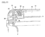
FIG. 11 is an enlarged sectional view showing the mechanism around the locking plate of the power tool storage case. -
FIG. 12 is a whole perspective view of a power tool storage case according to a third embodiment, in which the case is horizontally placed while a handle is tilted up into a use position and main locks and an auxiliary lock are locked. -
FIG. 13 is a whole perspective view of the power tool storage case according to the third embodiment, in which the case is horizontally placed while the handle is retreated to a storage position and the main locks and the auxiliary lock are unlocked. -
FIG. 14 is a sectional view taken in the direction of the arrow along the line III-III ofFIG. 13 , illustrating a vertical section of the auxiliary lock in an unlocked state while the case is horizontally placed. -
FIG. 15 is a sectional view taken in the direction of the arrow along the line IV-IV ofFIG. 12 , illustrating a vertical section of the auxiliary lock in a locked sate while the case is horizontally placed. -
FIG. 16 is a whole perspective view of the power tool storage case according to the third embodiment, illustrating a midway position before an auxiliary lid portion is closed, in which an operating lever of the auxiliary lock is returned to a locked position, with the result that a front end portion of an engagement lever comes into abutment on an upper part of a locking nail portion. In this figure, the handle is retreated to the storage position and the right and left main locks are locked. -
FIG. 17 is a whole perspective view of the power tool storage case according to the third embodiment, illustrating a state in which the main lid portion is opened while the auxiliary lock remains unlocked, with the result that the engagement lever of the auxiliary lock is caught by the locking nail portion and the auxiliary lid portion is held in an almost closed state. It should be noted that the interior of the case body is schematically shown and partitioning walls for securely holding pieces to be stored are omitted in this figure. Also in this figure, the power tool storage case is shown as being horizontally placed. -
FIG. 18 is a sectional view taken in the direction of the arrow along the line VII-VII ofFIG. 12 , illustrating a vertical section of the main lock in the locked sate while the case is horizontally placed. - With reference to the accompanying drawings, embodiments of the present invention will be described in detail.
- With reference to
FIGS. 1 and2 , a first embodiment of a power tool storage case (hereinafter simply referred to as a storage case) is shown. The storage case 1 is made of synthetic resin and includes amain body casing 2 shaped like an open rectangular box having a deep bottom, and alid member 3 shaped like a similar open rectangular box having a shallow bottom. In themain body casing 2, astorage portion 4 is formed, in which an electric power tool body such as a rechargeable impact driver (not shown), a battery pack (not shown), a battery charger (not shown), and the like are stored. Themain body casing 2 and thelid member 3 are hingedly connected to each other such that an opening at an upper side of themain body casing 2 and an opening at a lower side of thelid member 3 are facing to each other and rear surfaces (left side ofFIG. 2 corresponds to the front side) of themain body casing 2 and thelid member 3 are connected, at rear-side edges adjacent to the openings, by ashaft 5 to allow a relative rotation between thelid member 3 and themain body casing 2. - Front surfaces of the
main body casing 2 and thelid member 3 can be locked or unlocked by a pair of right andleft latches latch 6 is a so-called toggle latch or flip-over latch, in which an upper end of alever plate 7 is rotatably connected at an edge of the opening of themain body casing 2, and ahook plate 8 is rotatably connected at its lower end to an intermediate portion of thelever plate 7. Accordingly, while the upper end of thehook plate 8 is engaged with a projection (not shown) provided at an edge of the opening of thelid member 3, thelever plate 7 is flipped down so as to be parallel with the front face of themain body casing 2, so that thelid member 3 is locked with themain body casing 2 being closed. - The
reference number 9 indicates a handle provided on themain body casing 2 between thelatches handle 9 are rotatably connected to a pair of right and leftlower projections latches handle 9 is tilted down toward the front surface of themain body casing 2, thehandle 9 does not protrude forward from the front surfaces of thelower projections ribs handle 9 that is tilted down, continuously from the pair oflower projections - Further, a pair of right and left
upper projections lid member 3 in such positions that they form continuous profiles with thelower projections main body casing 2 when thelid member 3 is closed. - The upper surface of the
lid member 3 is recessed and divided into a plurality of spaces, which form asub-storage portion 13 for storing small pieces including bits. Further, on thelid member 3, there is provided anouter lid 14 for opening or closing the upper surface of thesub-storage portion 13. Thisouter lid 14 is a rectangular plate for covering the wholesub-storage portion 13, and includes a rear edge portion (not shown) which is formed by a bending down part of the rectangular plate. The rear edge portion is engaged in anengagement groove 13a extending in the right-and-left direction along the rear edge of thesub-storage portion 13, so that theouter lid 14 becomes rotatable around the rear edge portion. Acover portion 15 as a partitioning protrusion is provided in the right-and-left direction at a front center part of theouter lid 14 in such a manner as to protrude arcuately frontward and downward. Thecover portion 15 has both end portions which form continuous profiles with theupper projections lid member 3 in a state where thelid member 3 and theouter lid 14 are closed. - Further, a square-shaped
window 16 is formed in a front center part of theouter lid 14, and a lockingplate 17 as a locking portion is positioned in thewindow 16. As also shown inFIG. 3 , the lockingplate 17 is a rectangular-shaped plate fitted into thewindow 16 so that the upper surface of the lockingplate 17 becomes flush with the upper surface of theouter lid 14. Afinger rest hole 18 is formed in a rear portion of the lockingplate 17, and a plate-like stopper strip 19 having a forward-facingbarb 20 at its lower end is provided on and protrudes downward from a lower surface of the lockingplate 17 in a position forward of thefinger rest hole 18. Thebarb 20 has a slanted surface extending from the lower end. The slanted surface of thebarb 20 slants upward as it goes forward. - Further, a pair of
side walls plate 17 in positions forward of and outward of thestopper strip 19 in the right-and-left direction, and at the outer surfaces of the right and leftside walls shafts portions outer lid 14 at right and left edges of thewindow 16. Each of the receivingportion 23 has a receivinghole 24, into which one end of theshaft 22 is fitted. Accordingly, the lockingplate 17 is supported in thewindow 16 and becomes rotatable around theshafts - The front end of the locking
plate 17 forms athin plate portion 25, which is engageable with the front edge of thewindow 16 from below. As best seen inFIG. 3 , when the lockingplate 17 rotates in the clockwise direction of the figure, the upper surface of the lockingplate 17 does not move further beyond an engagement position at which the upper surface of the lockingplate 17 becomes flush with the upper surface of theouter lid 14. An L-shapedspring seat plate 26 is provided on the lower surface of theouter lid 14 at a front end portion of the lockingplate 17. Acoil spring 27 as an urging means is vertically positioned between thespring seat plate 26 and the front end portion of the lockingplate 17. Therefore, the lockingplate 17 is urged toward the engagement position at which thethin plate portion 25 abuts on the front end of thewindow 16. Thereference number 27a indicates a guide rod extending downward from the lower surface of the lockingplate 17 just behind thecoil spring 27. Theguide rod 27a is provided for preventing buckling of thecoil spring 27. - An
engagement plate 28 is provided on the bottom surface of thesub-storage portion 13 of thelid member 3, and astopper projection 29 as an engageable portion is formed at an upper end portion of theengagement plate 28. Thestopper projection 29 faces backward and protrudes toward thebarb 20. Theengagement plate 28 lies in a position parallel to and frontward of thestopper strip 19 of the lockingplate 17 when theouter lid 14 is closed. Thebarb 20 of thestopper strip 19 is engageable with thestopper projection 29 from below. Thestopper projection 29 has a slanted surface extending from the upper end. The slanted surface of thestopper projection 29 slants downward as it goes backward. - According to the storage case 1 as described in this first embodiment, when the
outer lid 14 is opened for loading or unloading small pieces to or from thesub-storage portion 13, a user inserts his finger into thefinger rest hole 18 of the lockingplate 17 and flips up the locking plate. By this operation, the lockingplate 17 rotates around theshaft FIG. 3 against the urging force of thecoil spring 27. As a result, thebarb 20 of thestopper strip 19 is rotated and disengaged from thestopper projection 29 into a disengagement position shown inFIG. 4 . Therefore, as best seen inFIGS. 5 and6 , theouter lid 14 is rotated in an upward direction around the rear edge portion to open thesub-storage portion 13. - Meanwhile, when the user rotates the
outer lid 14 to close thesub-storage portion 13, as best seen inFIG. 7 , thebarb 20 of thestopper strip 19 of the lockingplate 17 comes into contact with thestopper projection 29. Thereafter, as theouter lid 14 is rotated, thebarb 20 slips on and passes thestopper projection 29 because of the urging force of thecoil spring 27 and the guidance of the slanted surfaces. When theouter lid 14 reaches the closing position, the lockingplate 17 returns to the engagement position as shown inFIGS. 2 and3 , at which thebarb 20 is engaged with thestopper projection 29. Therefore, theouter lid 14 is automatically locked when thesub-storage portion 13 is closed by theouter lid 14. - According to the storage case 1 in the first embodiment, the locking
plate 17 is provided on theouter lid 14 so that when thesub-storage portion 13 is closed by theouter lid 14, the lockingplate 17 is moved to the engagement position at which thelocking plate 17 is engaged with thestopper projection 29 provided on thelid member 3. Further, the lockingplate 17 is movable from the engagement position to the disengagement position at which thelocking plate 17 is disengaged from thestopper projection 29. When the user closes thesub-storage portion 13 by theouter lid 14, theouter lid 14 can be automatically locked by the lockingplate 17. When the user opens theouter lid 14, the lockingplate 17 can be disengaged only by the lockingplate 17 being flipped up. Therefore, the opening/closing the outer lid can be realized with an excellent operability and thus excels in usability. - Especially in this first embodiment, since the
coil spring 27 is provided as an urging means for urging the lockingplate 17 toward the engagement position at which thelocking plate 17 engages with thestopper projection 29, the automatic engagement of the lockingplate 17 can be reliably performed. - Further, since the locking portion comprises the locking
plate 17 separately provided on theouter lid 14, the locking portion can be embodied in a preferable configuration. - Further, since the locking
plate 17 is provided to be flush with the outer surface of theouter lid 14, it is possible to decrease an occurrence of incidental disengagement of theouter lid 14 when the lockingplate 17 is trapped by an external object. - In addition, each of the
main body casing 2 and thelid member 3 is shaped like an open rectangular box, and themain body casing 2 and thelid member 3 are hingedly connected at their rear surfaces, which define a rear surface of the storage case 1. On the other hand, front surfaces of themain body casing 2 and thelid member 3 are locked or unlocked by a pair oflatches sub-storage portion 13 and theouter lid 14 with the lockingplate 17 are provided at the upper surface of thelid member 3. Therefore, the flipping up operation of the lockingplate 17 and the releasing operation of theouter lid 14 become substantially in the same movement direction, so that from the operations of flipping up of the lockingplate 17 to the operation of opening theouter lid 14 can be performed in a continuous and smooth manner. - Further, the
handle 9 is provided in the right-and-left direction at the front surface of the storage case 1, and thecover portion 15 which is parallel to thehandle 9 is provided on theouter lid 14 between the lockingplate 17 and thehandle 9. Therefore, thehandle 9 and the lockingplate 17 are partitioned, which prevents an erroneous operation of the lockingplate 17 upon holding thehandle 9. - A storage case according to a second embodiment of the present invention will be described below. The storage case in this embodiment is substantially the same as that described in the first embodiment except for the configuration around the locking plate. Parts similar to those previously described in the first embodiment are denoted by the same reference numerals, and detailed description thereof will be omitted. Description will be mainly given of the structure of the locking plate.
- As seen in
FIG. 8 , thestorage case 1a has acutout 30 at a front center part of theouter lid 14. Thecutout 30 extends beyond the front edge of theouter lid 14 and across the center part of thecover portion 15. Thecutout 30 becomes broader as it goes forward, and a lockingplate 31 is provided in thecutout 30. The lockingplate 31 is a plate-like member having an arcuately curved front end portion which extends downward in conformity with the curvature of thecover potion 15. As best seen inFIG. 9 , a pair of right and leftside walls plate 31, at a center part of the lockingplate 31 as viewed in the front-and-rear direction. A pair ofshafts side walls portions outer lid 14 at right and left edges of thecutout 30. Theshafts plate 31 are fitted into the corresponding receiving holes 35, 35 of the receivingportions plate 31 becomes rotatable with respect to theouter lid 14. In this second embodiment, athin plate portion 36 is formed at a rear end of the lockingplate 31, and thethin plate portion 36 is engageable with a rear edge of thecutout 30. Therefore, a further rotation of the lockingplate 31 in the anticlockwise direction can be prevented, and the lockingplate 31 does not move further beyond the engagement position between thethin plate portion 36 and the rear edge of thecutout 30. - Further, in this embodiment, a
stopper strip 37 is positioned slightly forward of theshafts barb 38 protrudes backward from thestopper strip 37. Anengagement plate 39 is positioned rearward of thestopper strip 37 and astopper projection 40 protrudes forward from theengagement plate 39. Similar to the first embodiment, thebarb 38 has a slanted surface extending from its lower end, and thestopper projection 40 has a slanted surface extending from its upper end. - As with the first embodiment, a
coil spring 41 is vertically positioned at the rear of thecutout 30 between aspring seat plate 42 extending from theouter lid 14 and the rear end portion of the lockingplate 31. Thecoil spring 41 urges the lockingplate 31 to rotate in the anticlockwise direction. Thereference number 43 indicates a guide rod, and thereference number 44 indicates a circular recessed portion formed on the upper surface of the lockingplate 31 at a position rearward of theshafts - According to the
storage case 1a as described in this second embodiment, when theouter lid 14 is opened for loading or unloading small pieces to or from thesub-storage portion 13, the user places his finger on the circular recessedportion 44 of the lockingplate 31 and then depresses the lockingplate 31 downward. By this operation, the lockingplate 31 rotates around theshafts FIG. 9 against the urging force of thecoil spring 41, so that thebarb 38 of thestopper strip 37 is caused to be rotated and disengaged from thestopper projection 40 into a disengagement position shown inFIG. 10 . Therefore, theouter lid 14 can be rotated in an upward direction around the rear edge portion to open thesub-storage portion 13. - Meanwhile, when the user rotates the
outer lid 14 to close thesub-storage portion 13, as best seen inFIG. 11 , thebarb 38 of thestopper strip 37 of the lockingplate 31 comes into abutment against thestopper projection 40. Thereafter, as theouter lid 14 is rotated, thebarb 38 slips on and passes thestopper projection 40 because of the urging force of thecoil spring 41 and the guidance of the slanted surfaces. When theouter lid 14 reaches the closing position, the lockingplate 31 again returns to the engagement position as shown inFIGS. 8 and9 , at which thebarb 38 is engaged with thestopper projection 40. Therefore, theouter lid 14 is automatically locked when thesub-storage portion 13 is closed by theouter lid 14. - According to the
storage case 1a in the second embodiment, the lockingplate 31 is provided on theouter lid 14 so that when thesub-storage portion 13 is closed by theouter lid 14, the lockingplate 31 is moved to the engagement position at which thelocking plate 31 is engaged with thestopper projection 40 provided on thelid member 3, and the lockingplate 31 is movable from the engagement position to the disengagement position at which thelocking plate 31 is disengaged from thestopper projection 40. When the user closes thesub-storage portion 13 by theouter lid 14, theouter lid 14 can be automatically locked by the lockingplate 31. When the user opens theouter lid 14, the lockingplate 31 can be disengaged only by flipping up the lockingplate 31. Therefore, the opening/closing theouter lid 14 can be realized with an excellent operability and thus excels in usability. - Especially in this second embodiment, since the
coil spring 41 is provided as an urging means for urging the lockingplate 31 toward the engagement position at which thelocking plate 31 engages with thestopper projection 40, the automatic engagement of the lockingplate 31 can be reliably performed. - Further, since the locking portion comprises the locking
plate 31 separately provided on theouter lid 14, the locking portion can be embodied in a preferable configuration. - Further, since the locking
plate 31 is provided to be flush with the outer surface of theouter lid 14, it is possible to decrease an occurrence of incidental disengagement of theouter lid 14 when the lockingplate 31 is trapped by an external object. - It is to be noted that in the above first and second embodiments, the urging means is not limited to a coil spring, and other elements such as a leaf spring and a resin spring may be used, where appropriate. Other modifications may also be possible. For example, a mechanism for rotatably supporting the locking plate may be modified by reversely providing the shafts and the corresponding receiving holes. The slanted surfaces of the barb and the stopper projection may not be necessary, and only one slanted surface may be provided on one of the barb and the stopper projection. As an alternative, a curved surface (curved surfaces) may be provided in place of the slanted surface (slanted surfaces).
- In the above first and second embodiments, the locking plate is provided to be flush with the outer surface of the outer lid. However, the locking plate may be dented inward from the outer surface of the outer lid.
- Further, in the above first and second embodiments, the locking plate is separately provided as a locking portion. However, an elastic strip integral with the outer lid may be used as a locking portion.
- In addition, according to the first and second embodiments, the urging means urges the locking plate toward the engagement position so that the automatic engagement of the locking plate is achieved. However, the locking plate may not have an urging means. For example, the outer lid may be provided with a locking plate capable of swinging between the engagement position and the disengagement position, whereas the lid member may be provided with a pressing member; the pressing member protrudes from the lid member and is urged so that when the outer lid is in a closed state, the pressing member contacts with the locking plate and urges the same toward the engagement position. By this arrangement, as soon as the user closes the outer lid, the locking plate brought into abutment with the pressing member is moved to the engagement position and locks the outer lid. On the other hand, when the user operates the locking plate so as to depress the pressing member and causes the locking plate to move into the disengagement position, the outer lid can be opened.
- Other than the above, the locking portion according to the present invention may be applicable to other configurations. For example, the outer lid may be shaped as a square or a trapezoid. The number of the sub-storage portion and the lid member may not be limited to one each, and for example, the sub-storage portion formed on the upper surface of the lid member may be opened or closed using a plurality of lid members. The sub-storage portion and the lid member may be provided at an outer surface of the main body casing.
- Of course, the configurations of the main body casing and the lid member may be modified, and further, the shape, the number, and the arrangement of the latches and/or the handle may be modified, where appropriate.
- With reference to
FIGS. 12 to 18 , a third embodiment of the present invention will be described. - A
storage case 100 in this third embodiment is a so-called plastic case. Thestorage case 100 provides a double storage space, in which an electric power tool body such as a rechargeable impact driver, and its accessories such as a battery pack, and a battery charger for the battery pack, and small pieces such as machine screws are all collectively stored in thestorage case 100 and carried together. Thestorage case 100 includes acase body 110 made of plastic, and amain lid portion 120 made of plastic and configured to open or close thecase body 110. - The
case body 110 is shaped like a rectangular box having an upper opening, and includes afront surface portion 111, right and leftside portions rear surface portion 114, and abottom plate portion 115. Thecase body 110 has a sufficient volume for storing relatively large objects such as an electric power tool body and a battery pack. The interior of thecase body 110 is divided by partitioning walls or the like so that stored objects can be retained without causing a rattle noise. - The
main lid portion 120 includes afront surface portion 121, right and leftside portions rear surface portion 124, and atop plate portion 125. As seen inFIGS. 14 ,15 and18 , therear surface portion 114 of thecase body 110 and therear surface portion 124 of themain lid portion 120 are hingedly connected together through ahinge portion 102. Themain lid portion 120 is rotated such that thefront surface portion 121 thereof moves in an upward or a downward direction, so that thecase body 110 is opened or closed by themain lid portion 120.FIG. 17 shows a state in which themain lid portion 120 is opened. - As seen in
FIGS. 14 ,15 and18 , when thestorage case 100 is placed on a working table D with thebottom plate portion 115 of thecase body 110 being in contact with the working table D, themain lid portion 120 faces upward and thecase body 110 is positioned under themain lid portion 120. This placement posture of thestorage case 100 is referred to as a horizontal posture in this specification. On the other hand, when thestorage case 100 is placed on the working table D with therear surface portion 114 of thecase body 100 and therear surface portion 124 of themain lid portion 120 being in contact with the working table D, thestorage case 100 is held in a stand-up posture. This placement posture of thestorage case 100 is referred to as a vertical posture in this specification. As seen inFIG. 17 , an opening/closing operation of themain lid portion 120 is carried out in the horizontal posture. Meanwhile, thestorage case 100 is portably carried in the vertical posture. - For the purpose of portably carrying the
storage case 1a, ahandle 116 is provided on thefront surface portion 111 of thecase body 110 in a central position along the right-and-left direction. Thehandle 116 has a substantially U-shaped configuration, and through both right and left side portions thehandle 116 is rotatably supported on thecase body 110. Thehandle 116 is vertically rotatable within 90 degrees. As best seen inFIGS. 12 and15 , thehandle 116 can be tilted up (in a direction shown by a thick open arrow (A)) into a use position at which thehandle 116 protrudes from thefront surface portion 111 substantially in the horizontal direction. On the contrary, as best seen inFIGS. 13 and14 , thehandle 116 can be tilted down into a storage position at which thehandle 116 is positioned along thefront surface portion 111. Thehandle 116 can be tilted down by the rotary movement of the user into the storage position, and tilted up into the use position from the storage position. When thestorage case 100 is placed in the horizontal posture, the handle moves into the storage position because of its own weight. The user can hold thehandle 116 retreated in the storage position and then tilt it up in the direction shown by the thick open arrow (A), so that thehandle 116 is rotated into the use position. - A pair of
main locks front surface portion 111 of thecase body 110. Each of themain locks lever 131 and anengagement lever 132. The operatinglever 131 is rotatably supported on thefront surface portion 111 of thecase body 110. The operatinglever 131 is rotatable in the vertical direction. Theengagement lever 132 is rotatably supported on the operatinglever 131 in such a manner that the axis of rotation of theengagement lever 132 is shifted from that of the operatinglever 131. Theengagement lever 132 is rotatable in the vertical direction with respect to the operatinglever 132. As best seen inFIG. 18 , the operatinglever 131 is supported on thefront surface portion 111 of thecase body 110 through a supportingshaft portion 131 a, so as to allow a vertical rotary movement of the operatinglever 131. Theengagement lever 132 is rotatably supported on the operatinglever 131 through a supportingshaft portion 132a. The supportingshaft portion 132a of theengagement lever 132 is shifted from the supportingshaft portion 131a of the operatinglever 131 toward a rotary distal end of the operatinglever 131. - Each of the right and left
main locks engagement lever 132 is hooked against a lockingnail portion 121a provided on thefront surface portion 121 of themain lid portion 120 and thereafter the operatinglever 131 is rotated in the downward direction. When themain locks main lid portion 120 is locked with respect to thecase body 110.FIGS. 12 and18 show a state in which both of the right and leftmain locks main locks lever 131 is rotated in the upward direction and thereafter the engagement of theengagement lever 132 with respect to the lockingnail portion 121a is disengaged.FIGS. 13 and16 show a state in which both of the right and leftmain locks main locks main lid portion 120 can be opened in the upward direction as shown inFIG. 17 . It should be noted that thehandle 116 and the right and leftmain locks - The
storage case 100 according to the third embodiment provides a double storage space, and in addition to the storage space in thecase body 110, anauxiliary storage space 140 for storing small pieces such as machine screws is provided in thetop plate portion 125 of themain lid portion 120. Anauxiliary lid portion 141 made of plastic is provided to open or close theauxiliary storage space 140. Theauxiliary lid portion 141 has a rectangular plate shape, and ahinge portion 141a is provided on the rear surface of theauxiliary lid portion 141 at the rear end edge thereof. Theauxiliary lid portion 141 is rotatably supported on thetop plate portion 125 of themain lid portion 120 through thehinge portion 141a so that theauxiliary lid portion 141 can be moved in the vertical direction to open or close theauxiliary storage space 140. Theauxiliary lid portion 141 corresponds to a small lid according to the conventional art. - An
auxiliary lock 150 for locking theauxiliary lid portion 141 in a locked state is provided, in place of a distal engagement portion of the conventional art, on thefront surface portion 121 of theauxiliary lid portion 141 in a central position along the right-and-left direction. As with themain locks auxiliary lock 150, which includes an operatinglever 151 and anengagement lever 152. The operatinglever 151 is rotatably supported on thefront surface portion 121 of theauxiliary lid portion 141 through a supportingshaft portion 151a. The operatinglever 151 is positioned at a center portion along the right-and-left direction and is rotatable in the vertical direction. The operatinglever 151 is movable between an unlocked position such as shown inFIGS. 13 and14 in which theoperating lever 151 protrudes from thefront surface portion 121 substantially in the horizontal direction and a locked position such as shown inFIGS. 12 ,15 and16 in which theoperating lever 151 has been rotated upward from the unlocked position and is positioned substantially along thefront surface portion 121. Theengagement lever 152 is rotatably supported on the operatinglever 151 through a supportingshaft portion 152a. The supportingshaft portion 152a of theengagement lever 152 is shifted from the supportingshaft portion 151a of the operatinglever 151 toward a rotary distal end of the operatinglever 151. Therefore, when the operatinglever 151 is rotatively operated, theengagement lever 152 and the supportingshaft portion 152a thereof move a large distance along the vertical direction. - Provided at a rotary distal end portion of the
engagement lever 152 is anengagement nail portion 152b. A lockingnail portion 153 is provided on thefront surface portion 121 of themain lid portion 120 corresponding to theengagement nail portion 152b. The lockingnail portion 153 is positioned at a center portion along the right-and-left direction of thefront surface portion 121. As best seen inFIGS. 12 and15 , when the operatinglever 151 is rotated upward into the locked position while theengagement nail portion 152b is engaged with the lockingnail portion 153 from below, theengagement lever 152 is hooked against the lockingnail portion 153 and theauxiliary storage space 140 is locked by theauxiliary lid portion 141. On the contrary, as best seen inFIGS. 13 and14 , when the operatinglever 151 is rotated downward into the unlocked position (e.g., in the direction shown by the thick open allow (B) ofFIGS. 12 and15 ), theengagement lever 152 also moves downward to disengage theengagement nail portion 152b from the lockingnail portion 153. Thereby, theauxiliary lock 150 can be unlocked. - As best seen in
FIG. 14 , when the operatinglever 151 is rotated into the unlocked position, the supportingshaft portion 152a moves toward the front surface side, with the result that theengagement lever 152 as a whole moves toward the front surface side. Further, since theengagement lever 152 is vertically hanged down from the operatinglever 151 by its own weight, theengagement nail portion 152b retreats from the lockingnail portion 153 in a direction toward the front surface side. Accordingly, if theauxiliary lid portion 141 is rotated upward, while being kept in this unlocked state, for opening theauxiliary lid portion 141, theengagement nail portion 152b of theengagement lever 152 passes through the lockingnail portion 153 at the front surface side and interference between theengagement nail portion 152b and the lockingnail portion 153 does not occur. - Accordingly, when the
auxiliary storage space 140 is opened, the user only rotates the operatinglever 151 downward (in the direction shown by the thick open allow (B)) into the unlocked position. By this operation, theengagement lever 152 reliably retreats from the lockingnail portion 153 by a sufficient distance. Therefore, if theauxiliary lid portion 141 is rotated upward from this position to open theauxiliary storage space 140, theengagement lever 152 passes upward through the lockingnail portion 153 at the front surface side without interference between theengagement lever 152 and the lockingnail portion 153. As a result, when the user opens theauxiliary lid portion 141, the user is not required to hold theengagement lever 152 and keep theengagement nail portion 152b of theengagement lever 152 away from the lockingnail portion 153 so as to prevent interference therebetween, so that the user can only rotate theauxiliary lid portion 141 in the upward direction. This makes it possible for the user to operate theauxiliary lid portion 141 by one hand in a simple and prompt manner. - When the user rotates the operating
lever 151 upward from the disengaged state shown inFIG. 14 into the locked position, theengagement lever 152 moves obliquely upward toward the rear surface side (i.e., in a direction diagonally upward inFIG. 14 from the lower left to the upper right) while being vertically hanged down from the operatinglever 151 through the supportingshaft portion 152a, and thereafter, as seen inFIG. 15 , theengagement nail portion 152b of theengagement lever 152 is brought into engagement with the lockingnail portion 153 from below to thereby lock theauxiliary lock 150. - Next, the user rotates the operating
lever 151 of theauxiliary lock 150 downward into the unlocked position. When the user opens themain lid portion 120 in the upward direction while theauxiliary lock 150 remains unlocked, theengagement lever 152 of theauxiliary lock 150 rotates by its own weight relative to the operatinglever 151. As a result, theengagement nail portion 152b of theengagement lever 152 moves toward the underside of the lockingnail portion 153. Accordingly, if the user rotates themain lid portion 120 upward while theauxiliary lock 150 remains unlocked, it is possible to prevent theauxiliary lid portion 141 from being unintentionally opened because theengagement lever 152 of theauxiliary lock 150 is caught by the lockingnail portion 153. - Similarly, even if the
storage case 100 is moved from the horizontal posture to the vertical posture while themain lid portion 120 is locked in the locked state with respect to thecase body 110 and the operatinglever 151 of theauxiliary lock 150 is rotated downward into the unlocked position to unlock theauxiliary lock 150, theengagement lever 152 of theauxiliary lock 150 rotates by its own weight relative to the operatinglever 151 and moves toward the underside of the lockingnail portion 153. Therefore, it is possible to prevent theauxiliary lid portion 141 from being unintentionally opened. - As described above, the
auxiliary lid portion 141 can be opened only by the user's desired releasing operation. Therefore, even if the user opens themain lid portion 120 with theauxiliary lock 150 being unlocked or even if the user lifts thestorage case 100 from the horizontal posture to the vertical posture, an unintentional release of theauxiliary lid portion 141 can be prevented, thereby avoiding scattering of small pieces stored in theauxiliary storage space 140. - Further, as seen in
FIGS. 14 and16 , a guidingsurface 153a is provided on the lockingnail portion 153 of theauxiliary lock 150. The guidingsurface 153a is formed at a front upper corner portion of the lockingnail portion 153, and slants downward toward the front surface side. According to this guidingsurface 153a, theauxiliary lid portion 141 can be closed in a reliable manner. - For example, as best seen in
FIG. 16 , in the case where the user closes theauxiliary lid portion 141 while thestorage case 100 is placed in the horizontal posture with themain lid portion 120 being closed with respect to thecase body 110, even if the distal end portion (engagement nail portion 152b) of theengagement lever 152 that is moved in the downward direction contacts (abuts on) the lockingnail portion 153 from above, the guidingsurface 153a guides the distal end portion of theengagement lever 152 in a direction away from the lockingnail portion 153. Therefore, as seen inFIG. 14 , the distal end portion of theengagement lever 152 is reliably restored toward the underside of the lockingnail portion 153. - Especially, as seen in
FIG. 16 , if the operatinglever 151 of theauxiliary lock 150 is unintentionally returned to the locked position while theauxiliary lid portion 141 is open, theengagement lever 152 closely approaches thefront surface portion 121. In this position, if the user closes theauxiliary lid portion 141, theengagement lever 152 is likely to abut on the lockingnail portion 153. However, according to this embodiment, since the guidingsurface 153a is provided on the upper part of the lockingnail portion 153, the distal end portion of the lockinglever 152 is guided in a direction away from the lockingnail portion 153 to avoid interference of the lockinglever 152 with the lockingnail portion 153. Therefore, theauxiliary lid portion 141 can be reliably closed. If theengagement lever 152 interferes with the upper part of the lockingnail portion 153 and is kept in an abutment state, a further closing operation of theauxiliary lid portion 141 is blocked. For this reason, the user has to move theengagement lever 152 away from the lockingnail portion 153. This tedious and time-consuming operation deteriorates the usability of thestorage case 100. However, according to theauxiliary lock 150 in this third embodiment, theauxiliary lid portion 141 can be closed in a reliable manner without requiring the above tedious and time-consuming operation, which results in enhancement of the usability of thestorage case 100. - According to the
storage case 100 as described previously in this third embodiment, themain lid portion 120 can be closed relative to thecase body 110 by the right and leftmain locks main locks case body 110. The engagement of theengagement lever 132 with respect to the lockingnail portion 121a can be disengaged by upwardly rotating the operatinglever 131 into a stand-up position, so that themain lid portion 120 can be opened in the upward direction. Meanwhile, theauxiliary lock 150 is provided on theauxiliary lid portion 141. When the user rotates the operatinglever 151 in the downward direction, the engagement of theengagement lever 152 with respect to the lockingnail portion 153 can be disengaged, so that theauxiliary lid portion 141 can be opened in the upward direction. - When the
storage case 100 is placed in the horizontal posture such as shown inFIG. 13 , thehandle 116 provided on thecase body 110 is retreated to the storage position because of its own weight. In the case where the user carries thestorage case 100 placed in the horizontal posture, the user first moves thehandle 116 from the storage position ofFIG. 13 into the use position ofFIG. 12 by tilting up thehandle 116 in the direction shown by the thick open arrow (A) (i.e., upward direction). During this operation, the user's hand holding thehandle 116 also moves thehandle 116 in the direction shown by the thick open arrow (A) (i.e., upward direction) so as to rotate thehandle 116 from a lower position, that is, the storage position to an upper position, that is, the use position. According to the conventional design, since the tilting up direction of the handle is the same as the flipping up direction of the auxiliary lock for unlocking the auxiliary lock, when the user moves his hand in the upward direction, his hand may unintentionally contacts the distal engagement portion of the small lid (auxiliary lid portion) and causes the small lid to be opened. However, according to thestorage case 100 in this third embodiment, theauxiliary lid portion 141 can be opened by rotating the operatinglever 151 of theauxiliary lock 150 in the downward direction to disengage theauxiliary lock 150. In other words, unlike the conventional configuration, theauxiliary lock 150 can be disengaged by rotating the operatinglever 151 in the opposite direction (i.e., direction shown by the thick open arrow (B)) to the user's hand movement direction for tilting up the handle (i.e., direction shown by the thick open arrow (A)). According to theauxiliary lock 150 in this third embodiment, it is possible to prevent theauxiliary lock 150 from being unintentionally unlocked when the user moves thehandle 116 into the use position. Therefore, it is possible to prevent theauxiliary lid portion 141 from being unintentionally opened. - Further, in the
auxiliary lock 150, the position of the supportingshaft portion 152a of theengagement lever 152 relative to the supportingshaft portion 151a of the operating lever 151 (i.e., the center distance between the supportingshaft portions lever 151 is disengaged, theengagement lever 152 is hanged down from the operatinglever 151 and kept away from the lockingnail portion 153 by a sufficient distance. Accordingly, the user is only required for rotating the operatinglever 151 downward to unlock theauxiliary lock 150, and there is no need to concern about interference of theengagement lever 152 with the lockingnail portion 153, nor does the user have to move theengagement lever 152, for example by his fingertip, so as to prevent theengagement nail portion 152b of theengagement lever 152 from being trapped with the lockingnail portion 153. Therefore, the user can easily open theauxiliary lid portion 141, which excels in usability of thestorage case 100. - Further, in the case where the user opens the
main lid portion 120 upward while thestorage case 100 is placed in the horizontal posture and the operatinglever 151 of theauxiliary lock 150 remains unlocked, or in the case where the user lifts thestorage case 100 from the horizontal posture to the vertical posture while the operatinglever 151 of theauxiliary lock 150 remains unlocked, theengagement lever 152 of theauxiliary lock 150 rotates to approach the lockingnail portion 153 while theengagement lever 152 is hanged down from the operatinglever 151 because of the action of gravity, and thereafter theengagement nail portion 152b of theengagement lever 152 is caught and engaged with the lockingnail portion 153. Therefore, in the case where the user opens themain lid portion 120 or lifts thestorage case 100 from the horizontal posture to the vertical posture, while he forgets that theauxiliary lock 150 remains unlocked, it is possible to prevent theauxiliary lid portion 141 from being unintentionally opened. This can also contribute to enhance the usability of thestorage case 100. - Further, according to the
auxiliary lock 150 in this third embodiment, if theengagement lever 152 abuts on the guidingsurface 153a of the lockingnail portion 153 during the process of closing theauxiliary lid portion 141 with thestorage case 100 being placed in the horizontal posture, theengagement lever 152 is guided in a direction away from the lockingnail portion 153 so as to avoid interference therebetween. Therefore, theauxiliary lid portion 141 can be closed completely. - Supposing that the guiding
surface 153a is not provided on the lockingnail portion 153 of theauxiliary lock 150, theengagement lever 152 of theauxiliary lock 150 may be disadvantageously locked during the process of closing theauxiliary lid portion 141 in a state where theengagement lever 152 contacts and abuts on the lockingnail portion 153 from above. In this instance, the user cannot completely close theauxiliary lid portion 141, so that theauxiliary lock 150 is not locked. For this reason, in addition to the closing operation of theauxiliary lid portion 141, the user has to move theengagement lever 152 away from the lockingnail portion 153, for example by using his fingertip, so as to eliminate the state where theengagement lever 152 abuts on the upper surface of the lockingnail portion 153. This tedious and time-consuming operation deteriorates the usability of thestorage case 100. However, according to the this embodiment, since the guidingsurface 153a is provided on the lockingnail portion 153, theauxiliary lid portion 141 can be closed without requiring the above tedious and time-consuming operation, which results in enhancement of the usability of thestorage case 100. - The present invention has been described in detail with reference to the third embodiment. However, the present invention is not limited to this specific embodiment, and various changes and modifications may be made without departing from the scope of the appended claims. For example, instead of providing the guiding
surface 153a on the lockingnail portion 153, a guiding surface (slanted surface) may be provided on theengagement lever 152 so as to avoid interference (i.e., locked into an abutment state) of theengagement lever 152 with the lockingnail portion 153. Further, a guiding surface for avoiding the interference may be provided on both theengagement lever 152 and the lockingnail portion 153. - In the third embodiment, the
auxiliary lid portion 141 is closed in the closed state by oneauxiliary lock 150. However, two or moreauxiliary locks - Further, in the third embodiment, the operating levers 131, 131 of the
main locks auxiliary lock 150. In this instance, the operating levers 131, 131 may be supported on thefront surface portion 121 of themain lid portion 120 and the lockingnail portion 121a may be provided on thefront surface portion 111 of thecase body 110. - It is explicitly stated that all features disclosed in the description and/or the claims are intended to be disclosed separately and independently from each other for the purpose of original disclosure as well as for the purpose of restricting the claimed invention independent of the composition of the features in the embodiments and/or the claims. It is explicitly stated that all value ranges or indications of groups of entities disclose every possible intermediate value or intermediate entity for the purpose of original disclosure as well as for the purpose of restricting the claimed invention, in particular as limits of value ranges.
Claims (16)
- A power tool storage case (1) for storing an electric power tool comprising:a main body casing (2) having a storage portion (4) configured to store an electric power tool;a lid member (3) hingedly connected to the main body casing (2) and capable of opening or closing the storage portion (4);a sub-storage portion (13) provided at an outer surface of the lid member (3); andan outer lid (14) hingedly connected to the lid member (3) and capable of opening or closing the sub-storage portion (13),characterized in that a locking portion is provided on the outer lid (14) so that when the sub-storage portion is closed by the outer lid (14), the locking portion is moved to an engagement position at which the locking portion is engaged with an engageable portion provided on the lid member (3), and that the locking portion is movable from the engagement position to a disengagement position at which the locking portion is disengaged from the engageable portion.
- The power tool storage case (1) according to claim 1, further comprising an urging means for urging the locking portion toward the engagement position.
- The power tool storage case (1) according to claim 1 or 2, wherein the locking portion comprises a locking plate (17) separately provided on the outer lid (14).
- The power tool storage case (1) according to any one of claims 1 to 3, wherein the locking portion is provided to be flush with or dented inward from an outer surface
- The power tool storage case (1) cording to any one of claims 1 to 4, wherein each of the main body casing (2) and the lid member (3) is shaped like an open rectangular box, and the main body casing (2) and the lid member (3) are hingedly connected at their rear surfaces, which define a rear surface of the power tool storage case (1), whereas front surfaces of the main body casing (2) and the lid member (3) are locked or unlocked by a pair of latches (6,6), and wherein the sub-storage portion (13) and the outer lid (14) having the locking portion are disposed at an upper surface of the lid member (3).
- The power tool storage case (1) according to any one of the preceding claims, wherein a handle (9) is provided in a right-and-left direction at a front surface of the power tool storage case (1), and wherein a partition projection which is parallel to the handle (9) is provided between the locking portion and the handle (9) on one of the lid member (3) and the outer lid (14).
- The power tool storage case (1) according to claim 6, when dependent on claim 5, wherein a pair of right and left projections are provided at the front surface of the power tool storage case (1) in such a manner as to protrude frontward from the latches (6,6) held in a locked state, and wherein both ends of the handle (9) are rotatably connected to the pair of right and left projections.
- The power tool storage case (1) according to claim 7, wherein the pair of right and left projections are continuously formed at both end portions of the partition projection.
- The power tool storage case (1) according to claim 7 or 8, wherein a pair of ribs extending in a vertical direction are formed outward of the handle (9), continuously from the pair of right and left projections.
- The power tool storage case (1) according to claim 3, wherein the locking plate (17) as a shaft (5) and the outer lid (14) has receiving holes for receiving the shaft (5), so that the locking plate (17) is rotatably supported on the outer lid (14) by fitting the shaft (5) into the receiving holes.
- The power tool storage case (1) according to claim 3 or 10, wherein the locking plate (17) is supported in a window or a cutout formed in the outer lid (14) and rotatable around an axis parallel to that of a hinge of the lid member (3), wherein a plate-like stopper strip (19) having a barb (20) at its lower end is provided on and protrudes downward from a lower surface of the locking plate (17) and a stopper projection (29) engageable with the barb (20) of the stopper strip is provided on and protrudes upward from a bottom surface of the lid member (3), the barb (20) and the stopper projection (29) being engageable with each other when the outer lid (14) is closed, and wherein the urging means is provided on the outer lid (14) so that the locking plate (17) is urged toward the engagement position at which the barb (20) is engaged with the stopper projection (29).
- The power tool storage case (1) according to claim 10 or 11, wherein each of the barb (20) and the stopper projection (29) has a slanted surface by which the barb (20) and the stopper projection (29) slip on and pass each other to guide the locking plate (17) to the engagement position.
- The power tool storage case (1) according to any one of claims 10 to 12, wherein the urging means is a coil spring (27) positioned between a spring seat plate (26) provided on the outer lid (14) and the locking plate (17).
- The power tool storage case (1) according to claim 13, wherein a guide rod is provided on and protrudes downward from the lower surface of the locking plate (17) along the coil spring (27), so as to prevent buckling of the coil spring (27).
- The power tool storage case (1) according to any one of claims 10 to 14, wherein an end portion of the locking plate (17) abuts on the outer lid (14) at the engagement position, so that the locking plate (17) is held in a position flush with or lower than the outer surface of the outer lid (14).
- The power tool storage case (1) according to claim 11, wherein a finger rest hole (18) is formed in the locking plate (17), through which the locking plate (17) is rotated into the disengagement position, or
wherein a circular recessed portion (44) is formed in an upper surface of the locking plate (17), through which the locking plate (17) is rotated into the disengagement position.
Applications Claiming Priority (2)
| Application Number | Priority Date | Filing Date | Title |
|---|---|---|---|
| JP2009294713A JP2011131357A (en) | 2009-12-25 | 2009-12-25 | Article storage case |
| JP2010188638A JP5698479B2 (en) | 2010-08-25 | 2010-08-25 | Power tool storage case |
Publications (3)
| Publication Number | Publication Date |
|---|---|
| EP2338650A2 true EP2338650A2 (en) | 2011-06-29 |
| EP2338650A3 EP2338650A3 (en) | 2013-07-24 |
| EP2338650B1 EP2338650B1 (en) | 2016-10-19 |
Family
ID=43797716
Family Applications (1)
| Application Number | Title | Priority Date | Filing Date |
|---|---|---|---|
| EP10195658.9A Active EP2338650B1 (en) | 2009-12-25 | 2010-12-17 | Power tool storage case |
Country Status (1)
| Country | Link |
|---|---|
| EP (1) | EP2338650B1 (en) |
Cited By (2)
| Publication number | Priority date | Publication date | Assignee | Title |
|---|---|---|---|---|
| US9248566B2 (en) | 2012-12-28 | 2016-02-02 | Makita Corporation | Tool housing case and subcase |
| EP3501756A1 (en) * | 2017-12-21 | 2019-06-26 | Hilti Aktiengesellschaft | Lock for a case |
Families Citing this family (1)
| Publication number | Priority date | Publication date | Assignee | Title |
|---|---|---|---|---|
| US11884456B2 (en) | 2020-09-25 | 2024-01-30 | Techtronic Cordless Gp | Tool storage system |
Citations (1)
| Publication number | Priority date | Publication date | Assignee | Title |
|---|---|---|---|---|
| JP2010064227A (en) | 2008-09-12 | 2010-03-25 | Hitachi Koki Co Ltd | Accommodating case for power tool |
Family Cites Families (5)
| Publication number | Priority date | Publication date | Assignee | Title |
|---|---|---|---|---|
| US5915553A (en) * | 1996-08-16 | 1999-06-29 | Akro-Mils | Storage organizers |
| US6527309B1 (en) * | 2001-09-19 | 2003-03-04 | Hardigg Industries, Inc. | Latch apparatus |
| US7334680B2 (en) * | 2003-01-15 | 2008-02-26 | Irwin Industrial Tool Company | Modular toolbox system |
| DE10310702A1 (en) * | 2003-03-10 | 2004-10-07 | BÖHLER, Christoph | Fastener for windows or specifically boxes uses sprung latch with grips both sides for closure round front axis and release round rear axis by finger pressure. |
| WO2008099404A1 (en) * | 2007-02-15 | 2008-08-21 | Keter Plastic Ltd. | Tool box |
-
2010
- 2010-12-17 EP EP10195658.9A patent/EP2338650B1/en active Active
Patent Citations (1)
| Publication number | Priority date | Publication date | Assignee | Title |
|---|---|---|---|---|
| JP2010064227A (en) | 2008-09-12 | 2010-03-25 | Hitachi Koki Co Ltd | Accommodating case for power tool |
Cited By (5)
| Publication number | Priority date | Publication date | Assignee | Title |
|---|---|---|---|---|
| US9248566B2 (en) | 2012-12-28 | 2016-02-02 | Makita Corporation | Tool housing case and subcase |
| EP3501756A1 (en) * | 2017-12-21 | 2019-06-26 | Hilti Aktiengesellschaft | Lock for a case |
| WO2019120836A1 (en) * | 2017-12-21 | 2019-06-27 | Hilti Aktiengesellschaft | Closure for a case |
| CN111465474A (en) * | 2017-12-21 | 2020-07-28 | 喜利得股份公司 | Closure for a box |
| CN111465474B (en) * | 2017-12-21 | 2022-11-22 | 喜利得股份公司 | Closure for a box |
Also Published As
| Publication number | Publication date |
|---|---|
| EP2338650B1 (en) | 2016-10-19 |
| EP2338650A3 (en) | 2013-07-24 |
Similar Documents
| Publication | Publication Date | Title |
|---|---|---|
| EP2522468B1 (en) | Power tool storage case | |
| US10112544B2 (en) | Vehicle armrest assembly | |
| JP4777123B2 (en) | Locking device | |
| EP3272983A1 (en) | Console lid opening/closing mechanism | |
| US9914398B1 (en) | Vehicle storage compartment | |
| US10697212B2 (en) | Console box | |
| EP2338650B1 (en) | Power tool storage case | |
| JP6506296B2 (en) | Rear cargo compartment structure of the vehicle | |
| JP5421620B2 (en) | Driving device for moving body | |
| JP4793200B2 (en) | Console box structure | |
| JP5698479B2 (en) | Power tool storage case | |
| JP5271547B2 (en) | Glove box lock unit mounting structure | |
| JP3723690B2 (en) | Console Box | |
| JP6863416B2 (en) | Power tool storage case | |
| JP4050539B2 (en) | Console Box | |
| JP6148876B2 (en) | Automotive center console | |
| JP5394029B2 (en) | Console Box | |
| JP5038174B2 (en) | Game machine locking device | |
| JP5134457B2 (en) | Vehicle storage box | |
| JP2013043624A (en) | Console box device | |
| JP5117111B2 (en) | Household thin paper storage container | |
| JP5097762B2 (en) | Shield cover opening and closing mechanism | |
| JP4446251B2 (en) | Opening door for vehicle storage box | |
| JP6628627B2 (en) | Lock structure | |
| JP4441235B2 (en) | Locking device for upper door in article storage fixture |
Legal Events
| Date | Code | Title | Description |
|---|---|---|---|
| PUAI | Public reference made under article 153(3) epc to a published international application that has entered the european phase |
Free format text: ORIGINAL CODE: 0009012 |
|
| AK | Designated contracting states |
Kind code of ref document: A2 Designated state(s): AL AT BE BG CH CY CZ DE DK EE ES FI FR GB GR HR HU IE IS IT LI LT LU LV MC MK MT NL NO PL PT RO RS SE SI SK SM TR |
|
| AX | Request for extension of the european patent |
Extension state: BA ME |
|
| RIC1 | Information provided on ipc code assigned before grant |
Ipc: B25H 3/02 20060101AFI20130228BHEP Ipc: E05B 65/52 20060101ALI20130228BHEP |
|
| PUAL | Search report despatched |
Free format text: ORIGINAL CODE: 0009013 |
|
| AK | Designated contracting states |
Kind code of ref document: A3 Designated state(s): AL AT BE BG CH CY CZ DE DK EE ES FI FR GB GR HR HU IE IS IT LI LT LU LV MC MK MT NL NO PL PT RO RS SE SI SK SM TR |
|
| AX | Request for extension of the european patent |
Extension state: BA ME |
|
| RIC1 | Information provided on ipc code assigned before grant |
Ipc: E05B 65/52 20060101ALI20130617BHEP Ipc: B25H 3/02 20060101AFI20130617BHEP |
|
| 17P | Request for examination filed |
Effective date: 20131126 |
|
| RBV | Designated contracting states (corrected) |
Designated state(s): AL AT BE BG CH CY CZ DE DK EE ES FI FR GB GR HR HU IE IS IT LI LT LU LV MC MK MT NL NO PL PT RO RS SE SI SK SM TR |
|
| 17Q | First examination report despatched |
Effective date: 20140220 |
|
| GRAP | Despatch of communication of intention to grant a patent |
Free format text: ORIGINAL CODE: EPIDOSNIGR1 |
|
| INTG | Intention to grant announced |
Effective date: 20160614 |
|
| GRAJ | Information related to disapproval of communication of intention to grant by the applicant or resumption of examination proceedings by the epo deleted |
Free format text: ORIGINAL CODE: EPIDOSDIGR1 |
|
| GRAR | Information related to intention to grant a patent recorded |
Free format text: ORIGINAL CODE: EPIDOSNIGR71 |
|
| GRAS | Grant fee paid |
Free format text: ORIGINAL CODE: EPIDOSNIGR3 |
|
| INTC | Intention to grant announced (deleted) | ||
| GRAA | (expected) grant |
Free format text: ORIGINAL CODE: 0009210 |
|
| INTG | Intention to grant announced |
Effective date: 20160908 |
|
| AK | Designated contracting states |
Kind code of ref document: B1 Designated state(s): AL AT BE BG CH CY CZ DE DK EE ES FI FR GB GR HR HU IE IS IT LI LT LU LV MC MK MT NL NO PL PT RO RS SE SI SK SM TR |
|
| REG | Reference to a national code |
Ref country code: GB Ref legal event code: FG4D |
|
| REG | Reference to a national code |
Ref country code: CH Ref legal event code: EP |
|
| REG | Reference to a national code |
Ref country code: AT Ref legal event code: REF Ref document number: 837925 Country of ref document: AT Kind code of ref document: T Effective date: 20161115 |
|
| REG | Reference to a national code |
Ref country code: IE Ref legal event code: FG4D |
|
| REG | Reference to a national code |
Ref country code: DE Ref legal event code: R096 Ref document number: 602010037281 Country of ref document: DE |
|
| REG | Reference to a national code |
Ref country code: NL Ref legal event code: MP Effective date: 20161019 |
|
| REG | Reference to a national code |
Ref country code: LT Ref legal event code: MG4D |
|
| PG25 | Lapsed in a contracting state [announced via postgrant information from national office to epo] |
Ref country code: LV Free format text: LAPSE BECAUSE OF FAILURE TO SUBMIT A TRANSLATION OF THE DESCRIPTION OR TO PAY THE FEE WITHIN THE PRESCRIBED TIME-LIMIT Effective date: 20161019 |
|
| REG | Reference to a national code |
Ref country code: AT Ref legal event code: MK05 Ref document number: 837925 Country of ref document: AT Kind code of ref document: T Effective date: 20161019 |
|
| PG25 | Lapsed in a contracting state [announced via postgrant information from national office to epo] |
Ref country code: SE Free format text: LAPSE BECAUSE OF FAILURE TO SUBMIT A TRANSLATION OF THE DESCRIPTION OR TO PAY THE FEE WITHIN THE PRESCRIBED TIME-LIMIT Effective date: 20161019 Ref country code: GR Free format text: LAPSE BECAUSE OF FAILURE TO SUBMIT A TRANSLATION OF THE DESCRIPTION OR TO PAY THE FEE WITHIN THE PRESCRIBED TIME-LIMIT Effective date: 20170120 Ref country code: LT Free format text: LAPSE BECAUSE OF FAILURE TO SUBMIT A TRANSLATION OF THE DESCRIPTION OR TO PAY THE FEE WITHIN THE PRESCRIBED TIME-LIMIT Effective date: 20161019 Ref country code: NO Free format text: LAPSE BECAUSE OF FAILURE TO SUBMIT A TRANSLATION OF THE DESCRIPTION OR TO PAY THE FEE WITHIN THE PRESCRIBED TIME-LIMIT Effective date: 20170119 |
|
| PG25 | Lapsed in a contracting state [announced via postgrant information from national office to epo] |
Ref country code: PL Free format text: LAPSE BECAUSE OF FAILURE TO SUBMIT A TRANSLATION OF THE DESCRIPTION OR TO PAY THE FEE WITHIN THE PRESCRIBED TIME-LIMIT Effective date: 20161019 Ref country code: BE Free format text: LAPSE BECAUSE OF FAILURE TO SUBMIT A TRANSLATION OF THE DESCRIPTION OR TO PAY THE FEE WITHIN THE PRESCRIBED TIME-LIMIT Effective date: 20161019 Ref country code: RS Free format text: LAPSE BECAUSE OF FAILURE TO SUBMIT A TRANSLATION OF THE DESCRIPTION OR TO PAY THE FEE WITHIN THE PRESCRIBED TIME-LIMIT Effective date: 20161019 Ref country code: ES Free format text: LAPSE BECAUSE OF FAILURE TO SUBMIT A TRANSLATION OF THE DESCRIPTION OR TO PAY THE FEE WITHIN THE PRESCRIBED TIME-LIMIT Effective date: 20161019 Ref country code: IS Free format text: LAPSE BECAUSE OF FAILURE TO SUBMIT A TRANSLATION OF THE DESCRIPTION OR TO PAY THE FEE WITHIN THE PRESCRIBED TIME-LIMIT Effective date: 20170219 Ref country code: HR Free format text: LAPSE BECAUSE OF FAILURE TO SUBMIT A TRANSLATION OF THE DESCRIPTION OR TO PAY THE FEE WITHIN THE PRESCRIBED TIME-LIMIT Effective date: 20161019 Ref country code: AT Free format text: LAPSE BECAUSE OF FAILURE TO SUBMIT A TRANSLATION OF THE DESCRIPTION OR TO PAY THE FEE WITHIN THE PRESCRIBED TIME-LIMIT Effective date: 20161019 Ref country code: FI Free format text: LAPSE BECAUSE OF FAILURE TO SUBMIT A TRANSLATION OF THE DESCRIPTION OR TO PAY THE FEE WITHIN THE PRESCRIBED TIME-LIMIT Effective date: 20161019 Ref country code: PT Free format text: LAPSE BECAUSE OF FAILURE TO SUBMIT A TRANSLATION OF THE DESCRIPTION OR TO PAY THE FEE WITHIN THE PRESCRIBED TIME-LIMIT Effective date: 20170220 Ref country code: NL Free format text: LAPSE BECAUSE OF FAILURE TO SUBMIT A TRANSLATION OF THE DESCRIPTION OR TO PAY THE FEE WITHIN THE PRESCRIBED TIME-LIMIT Effective date: 20161019 |
|
| REG | Reference to a national code |
Ref country code: DE Ref legal event code: R097 Ref document number: 602010037281 Country of ref document: DE |
|
| PG25 | Lapsed in a contracting state [announced via postgrant information from national office to epo] |
Ref country code: SK Free format text: LAPSE BECAUSE OF FAILURE TO SUBMIT A TRANSLATION OF THE DESCRIPTION OR TO PAY THE FEE WITHIN THE PRESCRIBED TIME-LIMIT Effective date: 20161019 Ref country code: RO Free format text: LAPSE BECAUSE OF FAILURE TO SUBMIT A TRANSLATION OF THE DESCRIPTION OR TO PAY THE FEE WITHIN THE PRESCRIBED TIME-LIMIT Effective date: 20161019 Ref country code: CZ Free format text: LAPSE BECAUSE OF FAILURE TO SUBMIT A TRANSLATION OF THE DESCRIPTION OR TO PAY THE FEE WITHIN THE PRESCRIBED TIME-LIMIT Effective date: 20161019 Ref country code: EE Free format text: LAPSE BECAUSE OF FAILURE TO SUBMIT A TRANSLATION OF THE DESCRIPTION OR TO PAY THE FEE WITHIN THE PRESCRIBED TIME-LIMIT Effective date: 20161019 Ref country code: DK Free format text: LAPSE BECAUSE OF FAILURE TO SUBMIT A TRANSLATION OF THE DESCRIPTION OR TO PAY THE FEE WITHIN THE PRESCRIBED TIME-LIMIT Effective date: 20161019 |
|
| REG | Reference to a national code |
Ref country code: CH Ref legal event code: PL |
|
| PLBE | No opposition filed within time limit |
Free format text: ORIGINAL CODE: 0009261 |
|
| STAA | Information on the status of an ep patent application or granted ep patent |
Free format text: STATUS: NO OPPOSITION FILED WITHIN TIME LIMIT |
|
| PG25 | Lapsed in a contracting state [announced via postgrant information from national office to epo] |
Ref country code: SM Free format text: LAPSE BECAUSE OF FAILURE TO SUBMIT A TRANSLATION OF THE DESCRIPTION OR TO PAY THE FEE WITHIN THE PRESCRIBED TIME-LIMIT Effective date: 20161019 Ref country code: BG Free format text: LAPSE BECAUSE OF FAILURE TO SUBMIT A TRANSLATION OF THE DESCRIPTION OR TO PAY THE FEE WITHIN THE PRESCRIBED TIME-LIMIT Effective date: 20170119 Ref country code: IT Free format text: LAPSE BECAUSE OF FAILURE TO SUBMIT A TRANSLATION OF THE DESCRIPTION OR TO PAY THE FEE WITHIN THE PRESCRIBED TIME-LIMIT Effective date: 20161019 |
|
| 26N | No opposition filed |
Effective date: 20170720 |
|
| GBPC | Gb: european patent ceased through non-payment of renewal fee |
Effective date: 20170119 |
|
| PG25 | Lapsed in a contracting state [announced via postgrant information from national office to epo] |
Ref country code: MC Free format text: LAPSE BECAUSE OF FAILURE TO SUBMIT A TRANSLATION OF THE DESCRIPTION OR TO PAY THE FEE WITHIN THE PRESCRIBED TIME-LIMIT Effective date: 20161019 |
|
| REG | Reference to a national code |
Ref country code: FR Ref legal event code: ST Effective date: 20170831 |
|
| REG | Reference to a national code |
Ref country code: IE Ref legal event code: MM4A |
|
| PG25 | Lapsed in a contracting state [announced via postgrant information from national office to epo] |
Ref country code: FR Free format text: LAPSE BECAUSE OF NON-PAYMENT OF DUE FEES Effective date: 20170102 Ref country code: LI Free format text: LAPSE BECAUSE OF NON-PAYMENT OF DUE FEES Effective date: 20161231 Ref country code: LU Free format text: LAPSE BECAUSE OF NON-PAYMENT OF DUE FEES Effective date: 20161217 Ref country code: CH Free format text: LAPSE BECAUSE OF NON-PAYMENT OF DUE FEES Effective date: 20161231 |
|
| PG25 | Lapsed in a contracting state [announced via postgrant information from national office to epo] |
Ref country code: GB Free format text: LAPSE BECAUSE OF NON-PAYMENT OF DUE FEES Effective date: 20170119 Ref country code: SI Free format text: LAPSE BECAUSE OF FAILURE TO SUBMIT A TRANSLATION OF THE DESCRIPTION OR TO PAY THE FEE WITHIN THE PRESCRIBED TIME-LIMIT Effective date: 20161019 Ref country code: IE Free format text: LAPSE BECAUSE OF NON-PAYMENT OF DUE FEES Effective date: 20161217 |
|
| PG25 | Lapsed in a contracting state [announced via postgrant information from national office to epo] |
Ref country code: CY Free format text: LAPSE BECAUSE OF FAILURE TO SUBMIT A TRANSLATION OF THE DESCRIPTION OR TO PAY THE FEE WITHIN THE PRESCRIBED TIME-LIMIT Effective date: 20161019 Ref country code: HU Free format text: LAPSE BECAUSE OF FAILURE TO SUBMIT A TRANSLATION OF THE DESCRIPTION OR TO PAY THE FEE WITHIN THE PRESCRIBED TIME-LIMIT; INVALID AB INITIO Effective date: 20101217 |
|
| PG25 | Lapsed in a contracting state [announced via postgrant information from national office to epo] |
Ref country code: TR Free format text: LAPSE BECAUSE OF FAILURE TO SUBMIT A TRANSLATION OF THE DESCRIPTION OR TO PAY THE FEE WITHIN THE PRESCRIBED TIME-LIMIT Effective date: 20161019 Ref country code: MK Free format text: LAPSE BECAUSE OF FAILURE TO SUBMIT A TRANSLATION OF THE DESCRIPTION OR TO PAY THE FEE WITHIN THE PRESCRIBED TIME-LIMIT Effective date: 20161019 |
|
| PG25 | Lapsed in a contracting state [announced via postgrant information from national office to epo] |
Ref country code: MT Free format text: LAPSE BECAUSE OF NON-PAYMENT OF DUE FEES Effective date: 20161217 |
|
| PG25 | Lapsed in a contracting state [announced via postgrant information from national office to epo] |
Ref country code: AL Free format text: LAPSE BECAUSE OF FAILURE TO SUBMIT A TRANSLATION OF THE DESCRIPTION OR TO PAY THE FEE WITHIN THE PRESCRIBED TIME-LIMIT Effective date: 20161019 |
|
| PGFP | Annual fee paid to national office [announced via postgrant information from national office to epo] |
Ref country code: DE Payment date: 20231031 Year of fee payment: 14 |