EP2338575B1 - Respiratory muscle endurance training device and method for the use thereof - Google Patents
Respiratory muscle endurance training device and method for the use thereof Download PDFInfo
- Publication number
- EP2338575B1 EP2338575B1 EP10192608.7A EP10192608A EP2338575B1 EP 2338575 B1 EP2338575 B1 EP 2338575B1 EP 10192608 A EP10192608 A EP 10192608A EP 2338575 B1 EP2338575 B1 EP 2338575B1
- Authority
- EP
- European Patent Office
- Prior art keywords
- chamber
- training device
- respiratory muscle
- valve
- patient
- Prior art date
- Legal status (The legal status is an assumption and is not a legal conclusion. Google has not performed a legal analysis and makes no representation as to the accuracy of the status listed.)
- Active
Links
- 210000003019 respiratory muscle Anatomy 0.000 title claims description 30
- 238000000034 method Methods 0.000 title description 8
- 239000007789 gas Substances 0.000 claims description 58
- 239000003570 air Substances 0.000 claims description 21
- 238000004891 communication Methods 0.000 claims description 7
- 239000012080 ambient air Substances 0.000 claims description 6
- 230000029058 respiratory gaseous exchange Effects 0.000 description 20
- 208000006545 Chronic Obstructive Pulmonary Disease Diseases 0.000 description 13
- 206010013975 Dyspnoeas Diseases 0.000 description 7
- 239000000443 aerosol Substances 0.000 description 6
- 230000000007 visual effect Effects 0.000 description 6
- 239000000463 material Substances 0.000 description 5
- 230000036961 partial effect Effects 0.000 description 5
- 230000003434 inspiratory effect Effects 0.000 description 4
- 210000004072 lung Anatomy 0.000 description 4
- 210000003205 muscle Anatomy 0.000 description 4
- 230000000241 respiratory effect Effects 0.000 description 4
- 238000009423 ventilation Methods 0.000 description 4
- 230000008901 benefit Effects 0.000 description 3
- 239000003550 marker Substances 0.000 description 3
- 239000000203 mixture Substances 0.000 description 3
- 238000007789 sealing Methods 0.000 description 3
- 125000006850 spacer group Chemical group 0.000 description 3
- 239000000126 substance Substances 0.000 description 3
- 241000272525 Anas platyrhynchos Species 0.000 description 2
- 208000006673 asthma Diseases 0.000 description 2
- 230000002596 correlated effect Effects 0.000 description 2
- 230000000875 corresponding effect Effects 0.000 description 2
- 230000008878 coupling Effects 0.000 description 2
- 238000010168 coupling process Methods 0.000 description 2
- 238000005859 coupling reaction Methods 0.000 description 2
- 229940079593 drug Drugs 0.000 description 2
- 239000003814 drug Substances 0.000 description 2
- 239000004973 liquid crystal related substance Substances 0.000 description 2
- 230000013011 mating Effects 0.000 description 2
- 229940071648 metered dose inhaler Drugs 0.000 description 2
- 230000002093 peripheral effect Effects 0.000 description 2
- 230000002829 reductive effect Effects 0.000 description 2
- PEDCQBHIVMGVHV-UHFFFAOYSA-N Glycerine Chemical compound OCC(O)CO PEDCQBHIVMGVHV-UHFFFAOYSA-N 0.000 description 1
- 206010020591 Hypercapnia Diseases 0.000 description 1
- 206010020952 Hypocapnia Diseases 0.000 description 1
- 239000004743 Polypropylene Substances 0.000 description 1
- 238000009825 accumulation Methods 0.000 description 1
- 230000006978 adaptation Effects 0.000 description 1
- 230000009286 beneficial effect Effects 0.000 description 1
- 230000036760 body temperature Effects 0.000 description 1
- 230000035565 breathing frequency Effects 0.000 description 1
- 230000008859 change Effects 0.000 description 1
- 230000003247 decreasing effect Effects 0.000 description 1
- 230000006735 deficit Effects 0.000 description 1
- 230000003292 diminished effect Effects 0.000 description 1
- 201000010099 disease Diseases 0.000 description 1
- 208000037265 diseases, disorders, signs and symptoms Diseases 0.000 description 1
- 230000004064 dysfunction Effects 0.000 description 1
- 230000001747 exhibiting effect Effects 0.000 description 1
- 230000006870 function Effects 0.000 description 1
- 208000000122 hyperventilation Diseases 0.000 description 1
- 230000001771 impaired effect Effects 0.000 description 1
- 230000000670 limiting effect Effects 0.000 description 1
- 238000004519 manufacturing process Methods 0.000 description 1
- 230000007246 mechanism Effects 0.000 description 1
- 239000006199 nebulizer Substances 0.000 description 1
- 238000011457 non-pharmacological treatment Methods 0.000 description 1
- 230000037081 physical activity Effects 0.000 description 1
- -1 polypropylene Polymers 0.000 description 1
- 229920001155 polypropylene Polymers 0.000 description 1
- 229920001296 polysiloxane Polymers 0.000 description 1
- 239000004800 polyvinyl chloride Substances 0.000 description 1
- 230000008569 process Effects 0.000 description 1
- 230000000750 progressive effect Effects 0.000 description 1
- 230000002685 pulmonary effect Effects 0.000 description 1
- 230000009325 pulmonary function Effects 0.000 description 1
- 230000000284 resting effect Effects 0.000 description 1
- 230000000717 retained effect Effects 0.000 description 1
- 230000035807 sensation Effects 0.000 description 1
- 208000024891 symptom Diseases 0.000 description 1
- 230000002123 temporal effect Effects 0.000 description 1
- 230000001225 therapeutic effect Effects 0.000 description 1
- 210000003813 thumb Anatomy 0.000 description 1
- 239000012780 transparent material Substances 0.000 description 1
- 238000011282 treatment Methods 0.000 description 1
- 230000003519 ventilatory effect Effects 0.000 description 1
- 230000002747 voluntary effect Effects 0.000 description 1
Images


Classifications
-
- A—HUMAN NECESSITIES
- A63—SPORTS; GAMES; AMUSEMENTS
- A63B—APPARATUS FOR PHYSICAL TRAINING, GYMNASTICS, SWIMMING, CLIMBING, OR FENCING; BALL GAMES; TRAINING EQUIPMENT
- A63B23/00—Exercising apparatus specially adapted for particular parts of the body
- A63B23/18—Exercising apparatus specially adapted for particular parts of the body for improving respiratory function
-
- A—HUMAN NECESSITIES
- A63—SPORTS; GAMES; AMUSEMENTS
- A63B—APPARATUS FOR PHYSICAL TRAINING, GYMNASTICS, SWIMMING, CLIMBING, OR FENCING; BALL GAMES; TRAINING EQUIPMENT
- A63B21/00—Exercising apparatus for developing or strengthening the muscles or joints of the body by working against a counterforce, with or without measuring devices
- A63B21/00058—Mechanical means for varying the resistance
- A63B21/00069—Setting or adjusting the resistance level; Compensating for a preload prior to use, e.g. changing length of resistance or adjusting a valve
-
- A—HUMAN NECESSITIES
- A63—SPORTS; GAMES; AMUSEMENTS
- A63B—APPARATUS FOR PHYSICAL TRAINING, GYMNASTICS, SWIMMING, CLIMBING, OR FENCING; BALL GAMES; TRAINING EQUIPMENT
- A63B21/00—Exercising apparatus for developing or strengthening the muscles or joints of the body by working against a counterforce, with or without measuring devices
- A63B21/008—Exercising apparatus for developing or strengthening the muscles or joints of the body by working against a counterforce, with or without measuring devices using hydraulic or pneumatic force-resisters
- A63B21/0085—Exercising apparatus for developing or strengthening the muscles or joints of the body by working against a counterforce, with or without measuring devices using hydraulic or pneumatic force-resisters using pneumatic force-resisters
-
- A—HUMAN NECESSITIES
- A63—SPORTS; GAMES; AMUSEMENTS
- A63B—APPARATUS FOR PHYSICAL TRAINING, GYMNASTICS, SWIMMING, CLIMBING, OR FENCING; BALL GAMES; TRAINING EQUIPMENT
- A63B71/00—Games or sports accessories not covered in groups A63B1/00 - A63B69/00
- A63B71/06—Indicating or scoring devices for games or players, or for other sports activities
- A63B71/0619—Displays, user interfaces and indicating devices, specially adapted for sport equipment, e.g. display mounted on treadmills
- A63B71/0622—Visual, audio or audio-visual systems for entertaining, instructing or motivating the user
- A63B2071/0625—Emitting sound, noise or music
-
- A—HUMAN NECESSITIES
- A63—SPORTS; GAMES; AMUSEMENTS
- A63B—APPARATUS FOR PHYSICAL TRAINING, GYMNASTICS, SWIMMING, CLIMBING, OR FENCING; BALL GAMES; TRAINING EQUIPMENT
- A63B2230/00—Measuring physiological parameters of the user
- A63B2230/40—Measuring physiological parameters of the user respiratory characteristics
- A63B2230/43—Composition of exhaled air
- A63B2230/433—Composition of exhaled air partial CO2 value
-
- A—HUMAN NECESSITIES
- A63—SPORTS; GAMES; AMUSEMENTS
- A63B—APPARATUS FOR PHYSICAL TRAINING, GYMNASTICS, SWIMMING, CLIMBING, OR FENCING; BALL GAMES; TRAINING EQUIPMENT
- A63B2230/00—Measuring physiological parameters of the user
- A63B2230/50—Measuring physiological parameters of the user temperature
Landscapes
- Health & Medical Sciences (AREA)
- General Health & Medical Sciences (AREA)
- Physical Education & Sports Medicine (AREA)
- Life Sciences & Earth Sciences (AREA)
- Biophysics (AREA)
- Orthopedic Medicine & Surgery (AREA)
- Pulmonology (AREA)
- Engineering & Computer Science (AREA)
- Human Computer Interaction (AREA)
- Measurement Of The Respiration, Hearing Ability, Form, And Blood Characteristics Of Living Organisms (AREA)
- Rehabilitation Tools (AREA)
Description
- The present disclosure relates generally to a training device, and in particular, to a respiratory muscle endurance training device.
- Patients with respiratory ailments, in particular patients with COPD (Chronic Obstructive Pulmonary Disease), have impaired exercise tolerance and diminished ventilatory efficiency. For example, one symptom of both asthma and COPD is Dyspnoea. Dyspnoea, exercise limitation and reduced quality of life are common features of COPD. Dyspnoea induces a progressive downward spiral that starts with physical activity. Thus, the intensity of Dyspnoea is increased when changes in respiratory muscle length or tension are inappropriate for the outgoing motor command, or when the requirement for respiratory work becomes excessive.
- There are a multitude of inputs to the sensation of Dyspnoea, few of which are readily modifiable. Dyspnoea may be alleviated by reducing the load placed upon the inspiratory muscles. Patients with COPD frequently have inspiratory muscle dysfunction, exhibiting weakness and reduced endurance. Patients with COPD may be well adapted to generating low flow rates for long periods of time, but this adaptation may rob them of the ability to generate the high pressures and flow rates required during exercise. The demand for exercise ventilation in patients with COPD may be elevated by their deconditioned state, inefficient breathing patterns, and gas exchange impairment.
- Various techniques have been developed to improve respiratory muscle endurance capacity. For example, one technique involves respiratory muscle training through the use of positive expiratory pressure devices, such as the AEROPEP PLUS valved holding chamber available from Trudell Medical International, the Assignee of the present application.
- Another technique is referred to as Respiratory Muscle Endurance Training (RMET). Most current RMET techniques require complicated and expensive equipment, which limits widespread use. Alternatively, a portable tube has been developed for use by COPD patients, and has been effective in improving the endurance exercise capacity of the users.
-
US 4291704 describes a spirometer device having an inflatable vessel with indicia to indicate the volume of air in the vessel at any particular time. Between the mouthpiece and the vessel there is also a valve element for preventing an escape of air from the vessel. -
US 4221381 describes a respiratory exerciser with a mouthpiece adapted to a chamber in which a slideable piston is located. The piston is inserted into the chamber in a non-airtight manner, so that air can pass between the piston wall and the tubular body. - The present invention provides a respiratory muscle endurance training device having the features as set out in claim 1.
- A respiratory muscle endurance training device includes a chamber and a patient interface. One or both of a CO2 sensor or a temperature sensor can be coupled to the chamber or patient interface to provide the user or caregiver with indicia about the CO2 level in, or the temperature of, the chamber or patient interface, and/or the duration of use of the device. In various embodiments, oneway inhalation and exhalation valves and flow indicators can also be associated with the chamber or patient interface.
- The respiratory muscle endurance training device includes a patient interface for transferring a patient's exhaled or inhaled gases and a fixed volume chamber in communication with the patient interface, where the fixed volume chamber is sized to retain a portion of a patient's exhaled gases. A variable volume chamber in communication with the fixed volume chamber, where the variable volume chamber is configured to be responsive to the patient's exhaled or inhaled gases to move from a first position to a second position. The variable orifice may be positioned on the variable volume chamber and permits a desired amount of exhaled air to escape during exhalation and to receive a supply of air to replace the escaped exhaled air during inhalation.
- In operation of the device according to the invention, the user inhales and exhales into the chamber. Over the course of a plurality of breathing cycles, the CO2 level in the chamber increases, thereby increasing the work of breathing and exercising the user's lungs. In other embodiments, a visual or audible indicator which may be located on the housing of the device may provide flashes or beeps, respectively, to prompt a patient to inhale or exhale at each such indication. In yet other embodiments, a visual or audible indicator that is separate from the device may be used to assist a patient in establishing the desirable breathing pattern.
- The various embodiments and aspects provide significant advantages over other respiratory muscle training devices. In particular, the training device is portable and the volume can be easily adjusted to accommodate different users, for example those with COPD, as well as athletes with healthy lungs. In addition, the user or care giver can quickly and easily assess the level or duration of use by way of various sensors, thereby providing additional feedback as to the proper use of the device. As such, pulmonary rehabilitation using respiratory muscle training can be implemented safely, for example and without limitation, in a home-based setting, thereby providing a relatively accessible non-pharmacological treatment for Dyspnoea, or other aspects of COPD, that also improve exercise intolerance and quality of life.
- The foregoing paragraphs have been provided by way of general introduction, and are not intended to limit the scope of the following claims. The presently preferred embodiments, together with further advantages, will be best understood by reference to the following detailed description taken in conjunction with the accompanying drawings.
-
-
FIG. 1 is a side view of one embodiment of a respiratory muscle endurance training device. -
FIG. 2 is a perspective view of an alternative embodiment of the respiratory muscle endurance training device ofFIG. 1 . -
FIG. 3 is a perspective view of the device ofFIG. 2 during exhalation with raised bellows. -
FIG. 4 is a cross-sectional view of the device ofFIG. 3 without a flexible tube. -
FIG. 5 is a top view of the device ofFIGS. 2-3 . -
FIG. 6 is a side view of another alternative embodiment of the respiratory muscle endurance training device. -
FIG. 7 is a cross-sectional view of the device ofFIG. 6 . -
FIG. 8 is an enlarged perspective view of a port assembly incorporated into the embodiment ofFIG. 6 . -
FIG. 9 is a cross-sectional view of the port assembly shown inFIG. 8 . -
FIG. 10 is a perspective view of another embodiment of a respiratory muscle endurance training device. -
FIG. 11 is a partial cross-sectional view of the device shown inFIG. 10 during an exhalation sequence. -
FIG. 12 is a partial cross-sectional view of the device shown inFIG. 10 during an inhalation sequence. -
FIG. 13 is a partial top view of the chamber shown inFIG. 10 with a top portion and valve cover removed. -
FIG. 14 is a partial top view of a top portion of the chamber shown inFIG. 10 . -
FIG. 15 is a partial bottom view of the top portion of the chamber shown inFIG. 14 . -
FIG. 16 is a bottom view of a valve cover. -
FIG. 17 is an exploded perspective view of a swivel connector. -
FIG. 18 is a cross-sectional view of the swivel connector shown inFIG. 17 . -
FIG. 19 is an exploded perspective view of a second swivel connector. -
FIG. 20 is a cross-sectional view of the swivel connector shown inFIG. 19 . -
FIGS. 21A-C are combined side and end views of the swivel connector shown inFIG. 19 with the variable opening positioned at different settings. - Referring to
FIG. 1 , a respiratory muscle endurance training device includes achamber 10, otherwise referred to as a spacer. In one embodiment, the chamber includes a first chamber component 2 and a second chamber component 3. In other embodiments, thechamber 10 is formed as a single unitary component. The first and second chambers define aninterior volume 12 of the chamber. - In one embodiment,
mating portions circumferential ribs 18 and/or seals (shown inFIG. 1 on the first chamber component) that mate with the other chamber to substantially prevent exhaled air from escaping from the chamber interface. In one embodiment, theribs 18 are spaced apart along the lengths of one or both of the chamber components so as to allow the chambers to be moved longitudinally in alongitudinal direction 20 relative to each other and then fixed at different lengths depending on the location of theribs 18 and amating shoulder 22 formed on the other chamber (shown inFIG. 1 as the second chamber component). The rings, or ribs, and shoulder are preferably integrally molded with the chambers, although they can also be affixed separately, e.g., as an o-ring. It should be understood that various detent mechanisms, including springs, tabs, etc. can be used to index the first chamber component relative to the second chamber component. Of course, it should be understood that the chambers can also be infinitely adjustable without any set detents, for example with a simple friction fit between the chamber components. - When adjusted, the overall
interior volume 12 of thechamber 10 can be adjusted. For example, theinterior volume 12 of the chamber can be adjusted from between about 500 cc to about 4000 cc. The chamber volume is adjusted depending on various predetermined characteristics of the user, such as peak expiratory flow. In this way, theinterior volume 12 can be adjusted to reduce or increase the total exhaled volume of expired gases captured inside thechamber 10. - The first chamber component 2 includes an
output end 24 that is coupled to a patient interface 1. It should be understood that the terms "coupling," "coupled," and variations thereof, mean directly or indirectly, and can include for example a patient interface in-molded with the first chamber at an output end thereof. The patient interface can be configured, without limitation, as a mask, a mouthpiece, a ventilator tube, etc. The term "output" merely refers to the fact that gas or air moves through or from the chamber to the patient interface during inhalation, notwithstanding that gas or air moves from the patient interface into the chamber during exhalation. The term "end" refers to a portion of the chamber that has an opening through which the gas or air moves, and can refer, for example, to a location on a spherical chamber having such an opening, with that portion of the sphere forming the "end." - The second chamber component 3 includes an
input end 28, wherein air or gas flows into thechamber 10. The chamber preferably includes a one-way inhalation valve 5 that allows ambient air, or aerosol from an aerosol delivery device, to flow in a one-way direction through theinput end 28 of the second chamber component and into theinterior volume 12. During an exhalation sequence of the user, anexhalation valve 34 opens to allow exhaled gases to escape to the ambient air. Theinhalation valve 5 is preferably configured as a duck-bill valve, although other valves such as slit petal valves, center post valves, valves having a central opening with a peripheral sealing edge, etc. would also work. One acceptable valve is the valve used in the AEROPEP PLUS device, available from Trudell Medical International. - The
exhalation valve 34 is preferably formed around a periphery of the inhalation valve. The second chamber 3 also includes a flow indicator 36, formed as a thin flexible member disposed in a viewing portion 38 formed on the second chamber, or as part of avalve cap 6. The flow indicator is configured to move during inhalation or exhalation to provide indicia to the user or caregiver that an adequate flow is being generated in the device. Various embodiments of the flow indicator and inhalation and exhalation valves are disclosed for example and without limitation inU.S. Patent No. 6,904,908 , assigned to Trudell Medical International, London, Ontario, Canada, the entire disclosure of which is hereby incorporated herein by reference. Examples of various aerosol delivery systems and valve arrangements are disclosed inU.S. Pat. Nos. 4,627,432 ,5,385,140 5,582,162 ,5,740,793 ,5,816,240 ,6,026,807 ,6,039,042 ,6,116,239 ,6,293,279 ,6,345,617 , and6,435,177 , the entire contents of each of which are incorporated herein by reference. Avalve chamber 7 is coupled to the input end of the second chamber. The valve chamber isolates and protects the valves from being contaminated or damaged, and further provides for coupling to a substance delivery device such as a tube or an aerosol delivery device. - The
chamber 10, for example the first chamber component 2 and/or the patient interface 1, is configured with a CO2 sensor 4, for example and without limitation a CO2 Fenem colormetric indicator available from Engineering Medical Systems, located in Indianapolis, Indiana. The CO2 indicator 4 provides visual feedback to the user and/or caregiver as to what the CO2 level is in thechamber 10, or the interior spaced defined by thechamber 10 and the patient interface 1, to ensure that the CO2 level is sufficient to achieve the intended therapeutic benefit. As shown inFIG. 1 , the sensor 4 is located at the output end of thechamber 10 adjacent the patient interface 1, or at the juncture of those components, whether formed integrally or separately. Of course, it should be understood that the sensor 4 can be located directly on or in the patient interface 1, or on or in either of the first and second chamber components 2, 3. - The expendable CO2 indicator 4 is configured with user indicia to indicate the level of CO2 in the chamber or interior. The indicator 4 includes a litmus paper with a chemical paper having a chemical material that reacts to the CO2 concentration in a gas. For example and without limitation, the color purple indicates an atmospheric concentration of CO2 molecules less than 0.03%. The color changes to a tan color at 2.0% CO2 in the gas. The color yellow indicates 5.0% or more CO2 concentration. At this level, the patient is re-inhaling expired gases (or dead space gases) to increase the concentration of CO2 in the lungs of the user, which encourages the user to inhale deeper, thereby exercising the lung muscles to expand beyond their normal condition. The sensor and indicator 4 can be used to determine the CO2 level, or the length of the time the user has been using the device. After use, the indicator 4 holds the reading for a period of time, so that a caregiver who is temporarily absent can get a reading after the use cycle is completed. Eventually the indicator will reset by returning to its original color scheme, such that it can be used again. The device is compact and lightweight, and is thus very portable.
- The device can also be configured with a
temperature sensor 40, such as a thermochromic liquid crystals strip, available from Hallcrest Inc., Glenview Illinois. Thetemperature sensor 40 is secured to the outside (or inside) of one of the chamber or user interface. A sensor can also be configured to measure the actual gas/air temperature inside the chamber. In one implementation, thetemperature sensor 40 may utilize cholestric liquid crystals (CLC). The temperature of the CLC is initially at room temperature. As the user successively breathes (inhales/exhales) through the device, the CLC will expand and contract depending on the temperature. Depending on the temperature, the color of the indicator will change, which also is indicative of, and can be correlated with, the length of time the user has been breathing through the device. - In one embodiment, an analog product line is used, which exhibits a line that moves throughout the temperature cycle and provides a direct correlation to the elapsed time of use. The temperature indicator can be configured to provide for an indication of temperature at least in a range from room temperature to slightly below the body temperature of the user, e.g., 37 degrees centigrade. A secondary temporal (e.g., minute) indicator can be located adjacent to the temperature indicator to provide an indication of how long the user has been using the device, with the temperature being correlated with the elapsed time. Again, the indicator can be configured to hold a reading, and then reset for subsequent and repeated use.
- The training device can be coupled to an aerosol delivery device (not shown), such as a nebulizer or metered dose inhaler, to deliver medication to the user through the chamber and patient interface. In this way, the device performs two (2) functions, (1) respiratory muscle endurance training and (2) treatment for respiratory ailments or diseases such as COPD or asthma. In one embodiment, the metered dose inhaler is engaged through an opening formed in the
valve chamber 7. - The materials used to manufacture the device may be the same as those used to make the AEROCHAMBER holding chambers available from Trudell Medical International of London, Ontario, Canada, which chambers are disclosed in the patents referenced and incorporated by reference above. The diameter of the
chambers 10, 2, 3 can range from between about 1 inch to about 6 inches. Although shown as cylindrical shapes, it should be understood that other cross-sectional shapes would also be suitable, including elliptical and rectangular shapes, although for devices also used for aerosol delivery, a cylindrical or elliptical shape is preferred to minimize impaction and loss of medication prior to reaching the patient. - Alternative embodiments of a respiratory muscle endurance training (RMET)
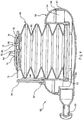
system 50 are illustrated inFIGS. 2-9 . In these embodiments, atube 52 is connectable with a chamber which may have a fixedvolume portion 54 defined by ahousing 56. A flexible bellows 58 defines anadjustable volume portion 60. Thetube 52 may be of a diameter ranging from 22 mm to 40 mm that provides a dead space volume (also referred to as rebreathing gas) of between 10 cubic centimeters (cc) to 40 cc per inch. The length may be varied between 10 inches to 36 inches in one embodiment. Thetube 52 may be corrugated tubing made of polyvinyl chloride (PVC) and have markings every six inches for reference when cutting to a desired length. The fixedvolume portion 54 defined by thehousing 56 may be manufactured in two sections to enclose 1600cc, however it may also be produced to have a volume in a range from 500 cc to 1600 cc in order to cover an expected range of patients from the small and thin to the large or obese. - The
housing 56 may be constructed from a polypropylene material or any of a number of other molded or formable materials. The housing may be manufactured in twohalves housing 56 may be fashioned in any of a number of shapes having a desired fixed volume. Hand rests 59, which may also be used as device resting pads, may be included on thehousing 56. The bellows 58 may be manufactured from a silicone or other flexible material and connected with thehousing 56 at a seal defined by arim 62 on thehousing 56 and a receivinggroove 64 on the end of thebellows 58 that is sized to sealably grip therim 62. In other embodiments, the bellows may be replaced with a balloon or other expandable body suitable for accommodating variable volumes. In the implementation ofFIGS. 2-4 , thehousing 56 may have a diameter of 6 inches and a height of 3.5 inches. Other sizes may be fabricated depending on the desired volume of gases. - As best shown in
FIG. 2 , thebellows 58 may be contained within thehousing 56 when no breathing is taking place using thesystem 50.FIGS. 2-3 illustrate theRMET system 50 with the bellows extended as a patient exhales. Avolume reference member 66 having ascale 68 applied thereto or embedded therein may be mounted on thehousing 56. The scale may be a linear scale such as a scale indicating increments of cc's, for example 100 cc increments from 0 to 500 cc. In one embodiment, thevolume reference member 66 is foldable against thehousing 56 byhinges 67 on the housing to permit a compact profile when not in use. Anindicator 70 connected with thebellows 58 moves with thebellows 58 during breathing so that its position adjacent thevolume reference member 66 on thehousing 56 will provide information relating to the volume for each patient breath.FIG. 2 illustrates theRMET system 50 when thebellows 58 are fully retracted, such as when the device is at rest or a patient is inhaling.FIGS. 3-4 illustrate thesystem 50 withbellows 58 extended during patient exhalation. - The
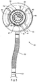
cap 74 on thebellows 58 defines avariable orifice 72 which may control the upper movement of thebellows 58 and define the final volume of theadjustable volume portion 60. Thevariable orifice 72 is set to allow excess exhaled gases to depart from the system to help prevent the patient from inhaling more than a desired percentage of the exhaled gases. In one embodiment, 60% of exhaled gases are desired for inhalation (rebreathing). In theRMET system 50 ofFIGS. 2-4 , thevariable orifice 72 also acts to allow fresh, inspired gases to enter into thesystem 50 when the patient inhales more than the volume contained in thesystem 50. In this manner, the additional 40% of gases necessary after the 60% of exhaled gases have been inhaled may be breathed in. Preferably, there are no valves in thevariable orifice 72 in order to allow the gases to flow freely through the system. By adjusting the resistance of thevariable orifice 72 to flow on exhalation, the height of the bellows is adjusted during exhalation and the desired mix of exhaled and fresh gases may be selected (in this example 60/40). - Referring to
FIGS. 4-5 , thevariable orifice 72 may be formed by overlapping portions, where anupper portion 76 has anopening 84 that may be rotated with respect to anunderlying portion 78 to selectively expose all or a portion of one ormore openings 86 in the underlying portion. Thevariable orifice 72 may be adjusted by pushing againstgrips 80 extending out from the upper portion so that the upper portion will rotate about a central axis. By pushing against thegrips 80 and turning theupper portion 76 with respect to thelower portion 78 about acentral axis 82, theopening 84 inupper portion 76 may be aligned with one ormore openings 86 in thelower portion 78. Although a rotatable arrangement is illustrated, other arrangements to vary an opening size are contemplated. - Referring to
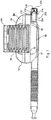
FIGS. 6-9 , a cap orouter cover 200 is disposed over the bellows to protect the bellows and provide a space for them to expand into. The cover is adjustably moveable relative to thehousing 56. The cover can be made of a transparent material so as to provide the user or caregiver with a view of the bellows and its state of expansion, or other indicia that may be provided inside the cover such as a volume reference number. - In addition, a
port 202 is formed in the housing and communicates with the fixedvolume reservoir 54. In one embodiment, theport 202 is configured as aseparate assembly 206 that is disposed in a channel formed in the housing. The port assembly includes aninsert portion 212 that is secured in the housing channel with a press fit, snap fit, mechanical or detent fasteners, bonding, etc., or combinations thereof. For example, the housing can be configured with arib 214 that engages a corresponding recess in the insert portion. In other embodiments, the port assembly can be integrally formed with the housing. In either embodiment, the port includes anorifice 204, configured in one embodiment as anopening 6 mm in diameter, although other size openings and dimensions may be suitable. If the port assembly is made separate from the housing, the housing may also include an orifice having the same or greater size than the port orifice, with the orifices being aligned. - The port is further configured with a
valve 210 disposed downstream of the orifice in the port assembly. The valve opens during exhalation. The valve can be configured as a one-way butterfly valve, although it should be understood that other types of valves, including annular valves, slit petal valves, center post valves, valves having a central opening with a peripheral sealing edge etc. can be used. The valve, while configured as a one-way valve, can also operate to a certain extent as a two-way valve, permitting a limited amount of ambient air to be entrained through the valve during inhalation before sealing up completely. Of course, as disclosed above with respect to the embodiment ofFIG. 1 , other combinations of inhalation and exhalation valves can be used in the port, whether separately provided or integrally formed so as to provide one-way inhalation or exhalation, or two-way inhalation and exhalation. In addition, while the port and valve are shown in communication with the fixed volume chamber, the port and valve could also be connected to and disposed in communication with the variable volume chamber. - A
cover 218, including a convex outer portion having at least oneopening 220 and in one embodiment a plurality of openings, is secured to the end of the port, for example by press. In one embodiment,annular flange 224 of the valve is secured between thecover 218 and the port housing. Thecover 218 also protects the valve and prevents tampering therewith. - The user fills and empties the
reservoir 60 completely during inspiration and expiration, while also inhaling additional fresh air through theport 202 during inspiration and breathing partly out through theport 202 during expiration. Thevalve 210 closes as the patient empties thereservoir unit 60 during inspiration. This assures constant Tidal Volume while breathing through the system. Theport 202 andvalve 210 can be used in place of thevariable orifice 72 of the embodiment inFIGS. 3-5 , or in conjunction therewith. Likewise, thevolume reference number 66 can be incorporated into the embodiment ofFIGS. 6-9 . - The size of the reservoir is adjusted to 50% to 60% of the subject's Vital Capacity. The breathing frequency is set at 60% of the patient's Maximum Voluntary Ventilation (MVV). To prevent Hypocapnia during breathing the reservoir volume is increased and hypercapnia is corrected by decreasing the reservoir volume. The user can also wear a nose clip to ensure that hey are breathing exclusively through the breathing device.
- Referring to
FIGS. 10-21C , a REMT system may be assembled from seven components. The REMT system allows for the patient to rebreathe 50-60% of the previous exhaled gases known as normocapnic hyperpnea to stimulate exercise training of the respiratory muscles. This inspiratory muscle training may have beneficial effects in certain patients with chronic obstructive pulmonary disease. - Referring to
FIGS. 10-12 , the REMT device includes amouthpiece 53, tubing 52 (including for example and without limitation corrugated tubing), aswivel connector 302,chamber 300, swivel connector with anadjustable orifice 304, and arebreathing bag 306, having for example and without limitation a 1 to 2 liter capacity. Thechamber 300 provides a fixed volume chamber, while the rebreathing bag provides a variable volume chamber. - Referring to
FIGS. 10 ,17 and 18 , theswivel connector 302 may be configured with a 22 mm inner diameter at oneend 312 and a 22 mm outer diameter on theother end 310. As shown inFIG. 10 , the swivel connector is attached to the chamber opening 308 at oneend 310 and thetubing 52 on theother end 312. The end portions of the connector are rotatable relative to each other. An O-ring, or other seal, is disposed between thecomponents corrugated tube 52 to easily mate with and rotate relative to thechamber 300. - The
mouthpiece 53,tubing 52, andswivel connector 302 each have a known volume, which are incorporated and included in the rebreathing of exhaled gases with a known volume of exhaled gases. In addition, the volume of thechamber 300 and the accumulated volume of therebreathing bag 306 as set by the user. In one embodiment, this total volume may represent between 50-60% of the total gas the patient will inhale during each breath. - Referring to
FIG. 11 , the route of the patient's exhaled gases is shown. In particular, a portion of the exhaled gas will pass through the restrictor swivel connectoradjustable orifice 304 into the reservoir, or rebreathingbag 306. The excess available exhaled gas will pass through thechamber 300 to the ambient atmosphere, and in particular, will pass through the one-way valve 320 andvariable orifice 322 in thechamber 300. - Referring to
FIG. 12 , the route of the inhaled gases is shown. In particular, gases may enter into theREMT chamber 300 from the outside of the chamber as well as from the reservoir or rebreathingbag 306 through theswivel connector 304 with the adjustable orifice. The combination of the two gas flows will provide the patient with a 50 to 60% rebreathing of exhaled gas collected in the system with each inhalation. - Referring to
FIGS. 13-16 , thechamber 302 may include abase 380 and a top 330 secured to the base. The top 330 has a 10mm hole 332 opening in a center portion thereof. Amovable valve holder 340 is configured with a plurality ofopenings FIG. 13 ). In one embodiment, the openings have respective diameters of 10, 8, and 6 mm. It should be understood that other size openings between 0 and 10 mm in diameter, or a different number of openings with different diameters can be provided. In addition, openings having non-circular shapes also can be provided. The openings in thevalve holder 340, which is rotatably connected to the top 330 and rotates about a vertical axis, interface with the10mm opening 334 in the top to create a variable size opening for the inhale/exhale gases to pass into and out of the chamber. - The
valve holder 340 includes agrippable member 350, such as a lever shaped to be engaged by a thumb, which permits the user to rotate the valve holder to a desired setting. The outside of the top 330 is provided withindicia 334, such as alphanumeric indicia, shown asnumbers member 350. In this way, the user sets the size of thevariable opening 322, defined by the interface of theopenings indicia 334. The indicia may also include color coding, tactile indicia, text, symbols, alphanumeric characters, or combinations thereof. The top 330 includes asemi-circular groove 352 or track, in which aguide member 354 on the valve holder moves. - A
valve 320, shown as a duck bill valve, is positioned between the openings and the ambient environment. The valve prevents a sudden inhalation of ambient or fresh gas/air due to a rapid inhalation from the subject. This is accomplished by the valve prevent substantial amounts of fresh/ambient gases from entering into the system. Any sudden inhalation of fresh/ambient air/gases may prevent the system from properly mixing the expired gases with the inhaled gases during inhalation procedure, or may otherwise result in a mixture outside of the 50-60% mixture of inhalation/exhalation gases. - A
valve cover 370 is configured with aspacer 372, configured in one embodiment for example and without limitation with an oval or elliptical cross section, which passes through the center of theduck bill valve 320 so as to maintain the valve in a partially open state. Thespacer 372, configured as a rod, is further configured with apassageway 374, or safety hole, shown as a 2 mm hole, which allows the patient to always have access to some atmosphere air if they completely empty the reservoir bag during inhalation. This will avoid a total stoppage of inhaled air during the patient's inhalation sequence due to an extra effort upon inhalation. Once thereservoir bag 306 is collapsed the patient will feel the resistance in the system through their breathing pattern and the patient will tend to stop inhaling and start to exhale. This keeps the breathing process continually operational. Thecover 370 is further provided with a plurality ofopenings 373 that allow the gases to pass from and to the ambient environment. The cover prevents access to and tampering with the valve. - The
base 380 has anopening 382, which may be a 22 mm opening, and which connects to the swivel connector with a variable orifice. The top is attached to the base and has anopening 384, which may be a 22 mm opening, to which the tubing is connected. - Referring to
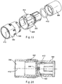
FIGS. 19-21C , theswivel connector 304 with a variable orifice is shown as including afirst end component 390, anintermediate component 392 and asecond end component 394.Indicia 396, shown for example as numerical indicia, are disposed circumferentially around an outer surface of thefirst end component 390. The indicia located on the outside surface correspond to the setting of a variable orifice, and in one embodiment may identify the size of the orifice at a particular setting, for example the number of millimeters in diameter the opening will be inside the connector. The size of the variable opening may control the amount of expired volume of gas collected in the reservoir or rebreathingbag 306, which may be determined by the flow of the gas from the patient and the size of the opening set at the output of thechamber 300. - The
first end component 390 may have a 22 mm opening and connects to thechamber 300, and in particular the base 380opening 382. Aninterior wall 398 has a curved moon 6mm opening 400 across the flow path of the connector. Theintermediate component 392 also is configured with aninterior wall 402 extending across the flow path. The intermediate component has a grippable surface, including for example and without limitation a plurality ofribs 406. Amarker 404 is provided on an exterior surface of the intermediate component. The interior wall is configured with acurved 6mm opening 408. Theintermediate component 392 is secured to and rotatable relative to thefirst end component 390 about alongitudinal axis 410, such that the twoopenings bag 306. Aseal 412, for example an O-ring, is disposed between theintermediate component 392 and thesecond end component 394, which in turn interfaces with the rebreathing bag 305. In this way, the rebreathing bag can be rotated relative to thechamber 300, for example by rotating thesecond component 394 relative to theintermediate component 392, without resetting or varying the size of the orifice. Rather, the size of the orifice is controlled by rotating theintermediate component 392 relative to thefirst end component 390. - In operation of the various systems, a patient first exhales into the patient interface, which may be a
mouthpiece 53, mask or other interface on the end of thecorrugated tubing 52. Upon the subsequent inhalation, the patient will inhale expired gases located in thecorrugated tubing 52, the fixedvolume portion adjustable volume portion variable orifice 72 on the flexible bellows 58 or on thechamber 300. The amount of exhaled gases may be set to be approximately 60% of the maximum voluntarily ventilation (MVV). To calculate how the level of ventilation may be set to approximately 60% of MW, one may multiply 35 × FEV1 (forced expiratory volume in the first second). This results in the relationship of 60% MW = 0.6 x 35 x FEV1. The dead space of theRMET system 50, in other words the amount of volume for holding exhaled gases, may be adjusted to 60% of the patient's inspiratory vital capacity (IVC). The breathing pattern of the patient must be set above the normal breaths per minute, which is generally 12 to 15 breaths per minute. A breathing pattern between 16 to 30 breaths per minute may be suitable depending on the patient. In the embodiments as described herein, the breathing pattern is preferably 20 breaths per minute. The embodiments as described herein may comprise a visual or audible indicator to assist the patient in establishing the desirable breathing pattern. For example, where the desired breathing pattern is 20 breaths per minute a visual indicator, such as a light, would flash on and off every 3 seconds prompting the patient to inhale every time the light is on or every time the light turns off. The visual or audible indicator could be located adjacent thevolume reference member 66. Although amouthpiece 53 may be directly connected with thehousing 56 as shown inFIG. 4 , thetubing 52 shown inFIGS. 2-3 permit greater flexibility in customizing the amount of exhaled air retained in thesystem 50. - Assuming that, on average, a COPD patient's IVC is approximately 3.3 liters, 60% of 3.3 liters is approximately 2 liters. To achieve this capacity with the
RMET system 50, an accumulation of a fixed volume plus a variable volume is used. The fixed volume with a flexible tubing 52 (120 cc to 240 cc) plus a fixedvolume portion 54 of 1600cc defined by thehousing 56, along with abellows 58 adjustable between approximately 0 cc to 400 cc accounts for the 60% of the IVC. During exhalation, 40% of the expired volume of gases may be expelled through thevariable orifice 72 in thebellows 58. During inhalation, the patient may inhale the exhaled volume of gases in thesystem 50 and inhale the remaining 40% of gases necessary to complete the IVC through thevariable orifice 72 on thebellows 58. To adjust the volume of expired gases collected from the patient, it is possible to reduce the length of the corrugated tube and reduce the fixed volume of gas in the device. - The patient observes the movement of the
indicator 70 against thescale 68 on the housing to determine that the 60% volume of the patient's IVC has been reached. A separate or integrated timing device (not shown), such as a mechanical or electronic timer emitting an audible and/or visible signal, can assist the patient to perform a breathing program at a sufficient rate of breaths per minute. It is contemplated that the initial setting of theRMET system 50 to 60% of a patient's specific IVC may be made by a caregiver. The caregiver or patient may, for example, use a pulmonary function machine to determine the patient's FEV1 which can then be used to calculate the patient's MVV and ultimately 60% of the IVC. - Although the present invention has been described with reference to preferred embodiments, those skilled in the art will recognize that changes may be made in form and detail without departing from the scope of the invention. As such, it is intended that the foregoing detailed description be regarded as illustrative rather than limiting and that it is the appended claims, which are intended to define the scope of the invention.
Claims (11)
- A respiratory muscle endurance training device comprising:a patient interface for transferring a patient's exhaled or inhaled gases;a fixed volume chamber (54; 56; 300) in communication with the patient interface, wherein the fixed volume chamber is sized to retain a portion of a patient's exhaled gases;a variable volume chamber (60; 306) in communication with the fixed volume chamber, wherein the variable volume chamber is configured to be responsive to the patient's exhaled or inhaled gases to move from a first position to a second position, and wherein the variable volume chamber is one of a rebreathing bag, preferable of 1 to 2 I in volume, a balloon and a bellows,a variable orifice (204; 304) adjustable for permitting a portion of exhaled air to escape to the ambient air during exhalation and receiving a supply of fresh air during inhalation.
- The respiratory muscle endurance training device of claim 1, wherein the portion of exhaled air to escape is 40 percent.
- The respiratory muscle endurance training device of claim 1 comprising a valve (210; 320) in communication with the fixed volume chamber.
- The respiratory muscle endurance training device of claim 3, wherein said valve is a one-way exhalation valve.
- The respiratory muscle endurance training device of claim 3 or 4, wherein said orifice is disposed between said valve and said fixed volume chamber.
- The respiratory muscle endurance training device of claim 5 comprising a port assembly containing said valve and said orifice, wherein said port assembly is connected to said fixed volume chamber.
- The respiratory muscle endurance training device of claim 4 comprising an outer cover (200) disposed between the valve and the ambient environment.
- The respiratory muscle endurance training device of claim 1 comprising a moveable cover (200) disposed over said variable volume chamber.
- The respiratory muscle endurance training device of claim 1, wherein variable size orifice is arranged with said interface and communicates between said fixed and variable volume chambers, and further comprising a second variable size orifice communicating with the ambient environment.
- The respiratory muscle endurance training device of claim 9 further comprising first indicia corresponding to a size of said second variable size orifice.
- The respiratory muscle endurance training device of claim 10 further comprising second indicia corresponding to a size of said variable size.
Applications Claiming Priority (2)
| Application Number | Priority Date | Filing Date | Title |
|---|---|---|---|
| US3043608P | 2008-02-21 | 2008-02-21 | |
| EP09712996A EP2259849A2 (en) | 2008-02-21 | 2009-02-19 | Respiratory muscle endurance training device and method for the use thereof |
Related Parent Applications (2)
| Application Number | Title | Priority Date | Filing Date |
|---|---|---|---|
| EP09712996.9 Division | 2009-02-19 | ||
| EP09712996A Division EP2259849A2 (en) | 2008-02-21 | 2009-02-19 | Respiratory muscle endurance training device and method for the use thereof |
Publications (2)
| Publication Number | Publication Date |
|---|---|
| EP2338575A1 EP2338575A1 (en) | 2011-06-29 |
| EP2338575B1 true EP2338575B1 (en) | 2017-05-31 |
Family
ID=40561923
Family Applications (2)
| Application Number | Title | Priority Date | Filing Date |
|---|---|---|---|
| EP10192608.7A Active EP2338575B1 (en) | 2008-02-21 | 2009-02-19 | Respiratory muscle endurance training device and method for the use thereof |
| EP09712996A Withdrawn EP2259849A2 (en) | 2008-02-21 | 2009-02-19 | Respiratory muscle endurance training device and method for the use thereof |
Family Applications After (1)
| Application Number | Title | Priority Date | Filing Date |
|---|---|---|---|
| EP09712996A Withdrawn EP2259849A2 (en) | 2008-02-21 | 2009-02-19 | Respiratory muscle endurance training device and method for the use thereof |
Country Status (4)
| Country | Link |
|---|---|
| US (3) | US8118713B2 (en) |
| EP (2) | EP2338575B1 (en) |
| CA (2) | CA2716511C (en) |
| WO (1) | WO2009105515A2 (en) |
Families Citing this family (44)
| Publication number | Priority date | Publication date | Assignee | Title |
|---|---|---|---|---|
| US8539951B1 (en) | 2008-05-27 | 2013-09-24 | Trudell Medical International | Oscillating positive respiratory pressure device |
| US8327849B2 (en) | 2008-10-28 | 2012-12-11 | Trudell Medical International | Oscillating positive expiratory pressure device |
| KR101005217B1 (en) * | 2008-10-29 | 2010-12-31 | 충북대학교 산학협력단 | One way air flow valve |
| EP2379128A4 (en) * | 2008-12-23 | 2014-02-05 | Us Gov Health & Human Serv | Lung aerosol collection device |
| US8485179B1 (en) | 2009-02-23 | 2013-07-16 | Trudell Medical International | Oscillating positive expiratory pressure device |
| US9149589B2 (en) | 2009-02-23 | 2015-10-06 | Trudell Medical International | Method and device for performing orientation dependent oscillating positive expiratory pressure therapy |
| DE102010004611A1 (en) * | 2009-08-11 | 2011-02-17 | Aceos Gmbh | User unit for the determination of performance parameters from respiratory gas analyzes |
| US11247003B2 (en) | 2010-08-23 | 2022-02-15 | Darren Rubin | Systems and methods of aerosol delivery with airflow regulation |
| CA3010658C (en) | 2011-06-06 | 2020-12-01 | Trudell Medical International | Oscillating positive expiratory pressure device |
| US20150047634A1 (en) * | 2012-03-17 | 2015-02-19 | University Health Network | Device for delivering hydrogen to a subject |
| US9517315B2 (en) | 2012-11-30 | 2016-12-13 | Trudell Medical International | Oscillating positive expiratory pressure device |
| US20140166004A1 (en) * | 2012-12-19 | 2014-06-19 | Carefusion 303, Inc. | Nebulizer with integrated breathing incentive |
| US9770566B2 (en) * | 2013-02-13 | 2017-09-26 | Jessica Meyers | Spirometer device with visual aid for therapeutic breathing |
| USD768845S1 (en) | 2013-06-12 | 2016-10-11 | M. LaQuisha Burkes | Expiratory muscle strength trainer adapter |
| USD753284S1 (en) | 2013-06-12 | 2016-04-05 | M. LaQuisha Burks | Expiratory muscle strength trainer adapter |
| EP3466396B1 (en) | 2013-07-12 | 2020-09-09 | Trudell Medical International | Huff cough simulation device |
| US9849257B2 (en) | 2013-08-22 | 2017-12-26 | Trudell Medical International | Oscillating positive respiratory pressure device |
| US9299267B2 (en) | 2013-10-08 | 2016-03-29 | Hector Antonio Perez | Resonance and articulation trainer |
| US10363383B2 (en) | 2014-02-07 | 2019-07-30 | Trudell Medical International | Pressure indicator for an oscillating positive expiratory pressure device |
| GB201420518D0 (en) * | 2014-11-19 | 2014-12-31 | Smiths Medical Int Ltd | Respiratory therapy apparatus |
| CN104436552B (en) * | 2014-11-28 | 2016-11-09 | 江南大学 | Respiration training |
| US10004872B1 (en) | 2015-03-06 | 2018-06-26 | D R Burton Healthcare, Llc | Positive expiratory pressure device having an oscillating valve |
| CN104784893A (en) * | 2015-04-23 | 2015-07-22 | 中国人民解放军第四军医大学 | Cigarette holder type lung function exercising device |
| MX2018001321A (en) * | 2015-07-30 | 2018-08-15 | Trudell Medical Int | Combined respiratory muscle training and oscillating positive expiratory pressure device. |
| ES2608969B1 (en) * | 2015-10-08 | 2017-09-28 | Oscar MEMBRADO LOPE | RESPIRATORY PHYSIOTHERAPY DEVICE |
| EP3383465B1 (en) | 2015-12-04 | 2021-02-03 | Trudell Medical International | Huff cough simulation device |
| MX2018009973A (en) * | 2016-02-16 | 2019-03-06 | Balancair Aps | A breathing device. |
| US9643048B1 (en) * | 2016-09-09 | 2017-05-09 | TrainingMask L.L.C. | Resistance breathing device |
| EP3618908A4 (en) | 2017-05-03 | 2021-01-13 | Trudell Medical International | Combined oscillating positive expiratory pressure therapy and huff cough simulation device |
| US10569132B2 (en) * | 2017-06-10 | 2020-02-25 | Bharat Pancholy | Incentive spirometer cap |
| EP3672671A1 (en) * | 2017-08-23 | 2020-07-01 | Balancair APS | Breathing device, app and interaction therebetween |
| NL2019578B1 (en) * | 2017-09-19 | 2019-03-28 | Milton Medical | Fidgeting device |
| US10953278B2 (en) | 2018-02-02 | 2021-03-23 | Trudell Medical International | Oscillating positive expiratory pressure device |
| EP3737475A4 (en) | 2018-02-16 | 2021-03-24 | University Of Louisville Research Foundation, Inc. | Respiratory training and airway pressure monitoring device |
| US10322312B1 (en) * | 2018-06-01 | 2019-06-18 | TrainingMask L.L.C. | Resistance and filtration breathing device |
| US11717634B2 (en) | 2018-10-02 | 2023-08-08 | MaxxO2, LLC | Therapeutic oxygen breathing apparatus and exercise system |
| US11395938B2 (en) * | 2019-01-31 | 2022-07-26 | Evolved, Llc | Respiratory training system |
| IT201900002317A1 (en) * | 2019-02-18 | 2020-08-18 | Pietro Maria Picotti | "Medical device for exercising the respiratory function of a user and a non-therapeutic method of monitoring and data collection" |
| CN110237505B (en) * | 2019-06-20 | 2020-07-14 | 浦江县人民医院 | Respiratory function training instrument |
| CN110279990B (en) * | 2019-08-13 | 2020-10-02 | 东阳市刚刚电器销售有限公司 | Breathing training device |
| USD958965S1 (en) * | 2019-11-27 | 2022-07-26 | Scuba Tuba Inc. | Underwater speaking chamber |
| CN112337058A (en) * | 2020-11-06 | 2021-02-09 | 北京市大兴区中西医结合医院 | Meridian-guided lung function compliance self-training device |
| CN112691346B (en) * | 2020-12-27 | 2022-01-04 | 宿录贞 | Recovered branch of academic or vocational study respiratory rehabilitation training device |
| CN113398542B (en) * | 2021-07-19 | 2022-06-21 | 南通市第一老年病医院(上海大学附属南通医院、南通市第六人民医院、南通市肺科医院) | Breathing rehabilitation is with expiration device that has vital capacity and detects function |
Family Cites Families (85)
| Publication number | Priority date | Publication date | Assignee | Title |
|---|---|---|---|---|
| US393869A (en) | 1888-12-04 | Inhaler | ||
| US2007330A (en) * | 1932-12-08 | 1935-07-09 | James H Hicks | Self-administering carbon dioxide apparatus |
| US2304033A (en) * | 1940-11-18 | 1942-12-01 | Florence L Shelton | Sanitary rebreathing bag |
| US2321256A (en) * | 1942-05-25 | 1943-06-08 | Florence L Shclton | Rebreathing bag |
| US2670739A (en) | 1951-07-02 | 1954-03-02 | Charles M Mcneill | Inhaler |
| US3043609A (en) | 1959-03-02 | 1962-07-10 | Talbert Construction Equipment | Removable gooseneck drawbar having an adjustable connection with a lowbed trailer |
| US3445294A (en) * | 1965-10-20 | 1969-05-20 | Allis Chalmers Mfg Co | Electrode backing plate for fuel cells |
| US3455294A (en) | 1966-02-25 | 1969-07-15 | Richard H Adler | Respiratory device |
| BE794580A (en) * | 1971-07-28 | 1973-05-16 | Connor Michael J O | RESPIRATOR |
| US3949984A (en) * | 1973-12-10 | 1976-04-13 | Joseph Navara | Breathing exerciser |
| US4182366A (en) | 1976-01-08 | 1980-01-08 | Boehringer John R | Positive end expiratory pressure device |
| US4231375A (en) | 1977-10-20 | 1980-11-04 | Boehringer John R | Pulmonary exerciser |
| FI56120C (en) | 1978-04-18 | 1979-12-10 | Taisto Haekkinen | VALVE AVSEDD FOER RESPIRATOR ELLER FOER ANNAN UPPLIVNINGSANVAENDNING LAEMPAD ANORDNING |
| US4192301A (en) * | 1978-11-06 | 1980-03-11 | Hardwick Charles W | Re-breathing apparatus |
| US4221381A (en) * | 1978-12-26 | 1980-09-09 | Albany International Corp. | Respiratory exerciser |
| US4275722A (en) * | 1979-05-04 | 1981-06-30 | Sorensen Harry D | Respiratory exerciser and rebreathing device |
| AU5112279A (en) | 1979-09-24 | 1981-04-02 | Becton Dickinson & Company | Volume measuring respiratory exerciser |
| US4291704A (en) * | 1979-12-13 | 1981-09-29 | Dale E. Braddy | Spirometer device |
| US4301810A (en) * | 1980-02-29 | 1981-11-24 | City Of Hope National Medical Center | Ventilatory muscle training apparatus |
| US4298023A (en) | 1980-09-09 | 1981-11-03 | Mcginnis Gerald E | Spring loaded exhalation valve |
| US4470412A (en) | 1982-03-19 | 1984-09-11 | Trutek Research, Inc. | Inhalation valve |
| FI79651C (en) | 1982-10-08 | 1990-02-12 | Glaxo Group Ltd | Dosing device for medicine |
| US4508116A (en) * | 1982-12-28 | 1985-04-02 | Products For Health And Industry | Carbon dioxide rebreathing apparatus |
| US4628926A (en) * | 1982-12-28 | 1986-12-16 | Products For Health And Industry, Inc. | Carbon dioxide rebreathing apparatus |
| JPS6099268A (en) | 1983-11-04 | 1985-06-03 | シャープ株式会社 | Constant flow control system |
| US4739987A (en) * | 1985-10-28 | 1988-04-26 | Nicholson Marguerite K | Respiratory exerciser |
| US4770413A (en) | 1987-04-27 | 1988-09-13 | Mba Healthcare Products, Inc. | Breathing exercise device |
| US4981295A (en) | 1987-05-11 | 1991-01-01 | City Of Hope | Respiratory training using feedback |
| US4854574A (en) * | 1988-03-15 | 1989-08-08 | 501 Healthscan, Inc. | Inspirator muscle trainer |
| EP0372148A1 (en) | 1988-12-09 | 1990-06-13 | Erik Folke Norell | Lung exercising device |
| US4938210A (en) * | 1989-04-25 | 1990-07-03 | Trudell Medical | Inhalation chamber in ventilator circuit |
| GB8909891D0 (en) | 1989-04-28 | 1989-06-14 | Riker Laboratories Inc | Device |
| BE1004384A3 (en) | 1989-08-03 | 1992-11-10 | Labaere Emmanuel | Device for applying on and techniques exhalation. |
| GB2238728B (en) | 1989-09-25 | 1993-04-07 | Christopher Harry Hepburn | A lung and chest exerciser and developer |
| US5103854A (en) * | 1990-01-22 | 1992-04-14 | Vernay Laboratories, Inc. | Low pressure check valve for artificial respiration devices |
| US5042467A (en) | 1990-03-28 | 1991-08-27 | Trudell Medical | Medication inhaler with fitting having a sonic signalling device |
| US5165393A (en) * | 1991-03-21 | 1992-11-24 | Kawaei Co., Ltd. | Deep breathing exercise apparatus |
| AU651882B2 (en) * | 1991-05-14 | 1994-08-04 | Visiomed Group Limited | Aerosol inhalation device |
| US5647345A (en) * | 1992-05-12 | 1997-07-15 | Saul; Gilbert D. | Respiratory stimulator & methods of use |
| AU653824B2 (en) * | 1992-06-15 | 1994-10-13 | Kawaei Co., Ltd. | Apparatus for supporting deep breathing and check valve for the same |
| NZ250105A (en) | 1992-11-09 | 1996-07-26 | Monaghan Canadian Ltd | Inhalator mask; one-way valve opens upon exhalation |
| SE9203570D0 (en) * | 1992-11-27 | 1992-11-27 | Astra Ab | INHALES FOR MULTIPLE USE |
| GB2278545B (en) * | 1993-04-21 | 1997-02-19 | Univ Loughborough | Inspiratory muscle training device |
| US5479920A (en) | 1994-03-01 | 1996-01-02 | Vortran Medical Technology, Inc. | Breath actuated medicinal aerosol delivery apparatus |
| US5598839A (en) | 1994-04-20 | 1997-02-04 | Diemolding Corporation | Positive expiratory pressure device |
| US5848588A (en) | 1994-05-25 | 1998-12-15 | Trudell Medical Group | Backpiece for receiving an MDI adapter in an aerosolization spacer |
| US5749368A (en) * | 1994-07-21 | 1998-05-12 | Kase; John C. | Breath air flow gauge |
| EP0808197A4 (en) | 1995-02-10 | 2001-03-28 | Everett D Hougen | A portable, personal breathing apparatus |
| US5658221A (en) | 1995-02-10 | 1997-08-19 | Hougen; Everett D. | Portable personal breathing apparatus and method of using same |
| US6083141A (en) * | 1995-02-10 | 2000-07-04 | Hougen; Everett D. | Portable respiratory exercise apparatus and method for using the same |
| AUPN417395A0 (en) * | 1995-07-14 | 1995-08-10 | Techbase Pty. Ltd. | An improved spacer |
| US5899832A (en) | 1996-06-14 | 1999-05-04 | Hougen; Everett D. | Compact lung exercising device |
| US6165105A (en) * | 1996-09-27 | 2000-12-26 | Boutellier; Urs | Apparatus and method for training of the respiratory muscles |
| US5755640A (en) * | 1996-12-04 | 1998-05-26 | Frolov; Vladimir F. | Endogenic breathing trainer |
| CA2212430A1 (en) * | 1997-08-07 | 1999-02-07 | George Volgyesi | Inhalation device |
| US6044841A (en) | 1997-08-29 | 2000-04-04 | 1263152 Ontario Inc. | Breath actuated nebulizer with valve assembly having a relief piston |
| US6345617B1 (en) * | 1997-09-26 | 2002-02-12 | 1263152 Ontario Inc. | Aerosol medication delivery apparatus and system |
| US6293279B1 (en) | 1997-09-26 | 2001-09-25 | Trudell Medical International | Aerosol medication delivery apparatus and system |
| JP2001518371A (en) | 1997-10-08 | 2001-10-16 | ボウテリール、ウルス | Training apparatus and training method for respiratory system |
| US6471621B2 (en) * | 1997-10-09 | 2002-10-29 | Ballon-Müller AG | Method of treatment of groups of muscles in an orofacial region by using an inflatable rubber balloon as logopedic aid |
| US5925831A (en) | 1997-10-18 | 1999-07-20 | Cardiopulmonary Technologies, Inc. | Respiratory air flow sensor |
| US6039042A (en) * | 1998-02-23 | 2000-03-21 | Thayer Medical Corporation | Portable chamber for metered dose inhaler dispensers |
| US6026807A (en) | 1998-02-27 | 2000-02-22 | Diemolding Corporation | Metered dose inhaler cloud chamber |
| US6631716B1 (en) * | 1998-07-17 | 2003-10-14 | The Board Of Trustees Of The Leland Stanford Junior University | Dynamic respiratory control |
| AU1242600A (en) | 1998-11-06 | 2000-05-29 | Salter Labs | Nebulizer mouthpiece and accessories |
| US6390090B1 (en) * | 1998-12-31 | 2002-05-21 | Samuel David Piper | Inhalation therapy apparatus |
| DE19912337C1 (en) | 1999-03-19 | 2000-08-17 | Arkadi Prokopov | Portable breathing mask for training under low oxygen conditions has an adjustable hose connection at the mask to set the mixture of ambient oxygen-rich air with low-oxygen air from the breathing bag |
| JP4777569B2 (en) | 1999-12-06 | 2011-09-21 | ファーレンハイト・212・リミテッド | Breathing method and apparatus |
| US6240917B1 (en) | 1999-12-20 | 2001-06-05 | Joseph R. Andrade | Aerosol holding chamber for a metered-dose inhaler |
| US6412481B1 (en) | 1999-12-23 | 2002-07-02 | Robert Bienvenu | Sealed backpressure attachment device for nebulizer |
| US6408848B1 (en) * | 2000-03-28 | 2002-06-25 | Ntc Technology, Inc. | Method and apparatus for conveniently setting a predetermined volume for re-breathing |
| CA2733850C (en) * | 2000-04-11 | 2013-10-22 | Trudell Medical International | Aerosol delivery apparatus with positive expiratory pressure capacity |
| US7971588B2 (en) | 2000-05-05 | 2011-07-05 | Novartis Ag | Methods and systems for operating an aerosol generator |
| US6584969B2 (en) * | 2000-12-07 | 2003-07-01 | Michael W. Farmer | Inhalation therapy assembly and method |
| US20020104531A1 (en) | 2001-01-18 | 2002-08-08 | Rand Malone | Pediatric inhalation device |
| ES2284824T3 (en) | 2001-04-10 | 2007-11-16 | Idiag | TRAINING EQUIPMENT FOR RESPIRATORY FUNCTION AND CONTROL PROCEDURE FOR THE SUPPLY OF FRESH AIR. |
| AU2002362045A1 (en) | 2001-12-04 | 2003-06-17 | Minnesota High-Tech Resources, Llc | Breathable gas mixtures to change body temperature |
| GB0205759D0 (en) | 2002-03-12 | 2002-04-24 | Southbank University Entpr Ltd | Improved breathing apparatus |
| WO2003092777A1 (en) | 2002-05-03 | 2003-11-13 | Trudell Medical International | Aerosol medication delivery apparatus with narrow orifice |
| US6904908B2 (en) * | 2002-05-21 | 2005-06-14 | Trudell Medical International | Visual indicator for an aerosol medication delivery apparatus and system |
| EP1558312B1 (en) | 2002-06-28 | 2017-08-09 | The Research Foundation of the State University of New York | Therapeutic agent delivery device and method |
| GB0217198D0 (en) | 2002-07-25 | 2002-09-04 | Glaxo Group Ltd | Medicament dispenser |
| US7360537B2 (en) | 2003-04-16 | 2008-04-22 | Trudell Medical International | Antistatic medication delivery apparatus |
| US7267121B2 (en) | 2004-04-20 | 2007-09-11 | Aerogen, Inc. | Aerosol delivery apparatus and method for pressure-assisted breathing systems |
| EP2059309B1 (en) * | 2006-08-21 | 2013-07-03 | Trudell Medical International | Respiratory muscle endurance training device and method for the use thereof |
-
2009
- 2009-02-19 US US12/388,952 patent/US8118713B2/en active Active
- 2009-02-19 WO PCT/US2009/034474 patent/WO2009105515A2/en active Application Filing
- 2009-02-19 EP EP10192608.7A patent/EP2338575B1/en active Active
- 2009-02-19 CA CA2716511A patent/CA2716511C/en active Active
- 2009-02-19 CA CA2884941A patent/CA2884941C/en active Active
- 2009-02-19 EP EP09712996A patent/EP2259849A2/en not_active Withdrawn
-
2012
- 2012-01-25 US US13/357,914 patent/US8663069B2/en active Active
-
2014
- 2014-02-12 US US14/179,153 patent/US20150031506A1/en not_active Abandoned
Also Published As
| Publication number | Publication date |
|---|---|
| WO2009105515A2 (en) | 2009-08-27 |
| US20090239711A1 (en) | 2009-09-24 |
| CA2884941C (en) | 2017-03-14 |
| CA2884941A1 (en) | 2009-08-27 |
| US8118713B2 (en) | 2012-02-21 |
| US8663069B2 (en) | 2014-03-04 |
| CA2716511A1 (en) | 2009-08-27 |
| EP2259849A2 (en) | 2010-12-15 |
| EP2338575A1 (en) | 2011-06-29 |
| CA2716511C (en) | 2015-06-02 |
| US20120270703A1 (en) | 2012-10-25 |
| WO2009105515A3 (en) | 2009-10-15 |
| US20150031506A1 (en) | 2015-01-29 |
Similar Documents
| Publication | Publication Date | Title |
|---|---|---|
| EP2338575B1 (en) | Respiratory muscle endurance training device and method for the use thereof | |
| EP2059309B1 (en) | Respiratory muscle endurance training device and method for the use thereof | |
| US5598839A (en) | Positive expiratory pressure device | |
| EP0836518B1 (en) | A portable, personal breathing apparatus | |
| US6083141A (en) | Portable respiratory exercise apparatus and method for using the same | |
| US8272378B2 (en) | System and method for improving endurance of inspiratory muscles | |
| US20160346603A1 (en) | Pulmonary System Resistance Training Apparatus and Methods | |
| EP2491987B1 (en) | Device for evaluating and training respiratory function, on both inspiration and expiration | |
| WO2004052463A1 (en) | Breathing apparatus for hypoxic pre-acclimatization and training | |
| WO2004096110A2 (en) | Pursed lip breathing device | |
| US20140274568A1 (en) | Combination spirometer and pep breathing exerciser | |
| SU1722507A1 (en) | Device for prophylaxis of respiratory system diseases | |
| RU2346706C1 (en) | Method and respiratory gymnastics apparatus with bypass | |
| RU1799589C (en) | Device for normalizing functions and training respiratory system | |
| TWM444848U (en) | Respiratory training device | |
| KR20220061625A (en) | Breath builder with rotating variable device | |
| ES1306247U (en) | Mouth fixation device for physical training. (Machine-translation by Google Translate, not legally binding) | |
| CA2226646A1 (en) | Canadian lung care device |
Legal Events
| Date | Code | Title | Description |
|---|---|---|---|
| PUAI | Public reference made under article 153(3) epc to a published international application that has entered the european phase |
Free format text: ORIGINAL CODE: 0009012 |
|
| AC | Divisional application: reference to earlier application |
Ref document number: 2259849 Country of ref document: EP Kind code of ref document: P |
|
| AK | Designated contracting states |
Kind code of ref document: A1 Designated state(s): AT BE BG CH CY CZ DE DK EE ES FI FR GB GR HR HU IE IS IT LI LT LU LV MC MK MT NL NO PL PT RO SE SI SK TR |
|
| AX | Request for extension of the european patent |
Extension state: AL BA RS |
|
| 17P | Request for examination filed |
Effective date: 20111229 |
|
| REG | Reference to a national code |
Ref country code: DE Ref legal event code: R079 Ref document number: 602009046432 Country of ref document: DE Free format text: PREVIOUS MAIN CLASS: A63B0023180000 Ipc: A63B0071060000 |
|
| GRAP | Despatch of communication of intention to grant a patent |
Free format text: ORIGINAL CODE: EPIDOSNIGR1 |
|
| RIC1 | Information provided on ipc code assigned before grant |
Ipc: A63B 21/008 20060101ALI20160913BHEP Ipc: A63B 23/18 20060101ALI20160913BHEP Ipc: A63B 21/00 20060101ALI20160913BHEP Ipc: A63B 71/06 20060101AFI20160913BHEP |
|
| INTG | Intention to grant announced |
Effective date: 20161012 |
|
| GRAS | Grant fee paid |
Free format text: ORIGINAL CODE: EPIDOSNIGR3 |
|
| GRAA | (expected) grant |
Free format text: ORIGINAL CODE: 0009210 |
|
| AC | Divisional application: reference to earlier application |
Ref document number: 2259849 Country of ref document: EP Kind code of ref document: P |
|
| AK | Designated contracting states |
Kind code of ref document: B1 Designated state(s): AT BE BG CH CY CZ DE DK EE ES FI FR GB GR HR HU IE IS IT LI LT LU LV MC MK MT NL NO PL PT RO SE SI SK TR |
|
| REG | Reference to a national code |
Ref country code: CH Ref legal event code: EP Ref country code: GB Ref legal event code: FG4D |
|
| REG | Reference to a national code |
Ref country code: AT Ref legal event code: REF Ref document number: 896902 Country of ref document: AT Kind code of ref document: T Effective date: 20170615 |
|
| REG | Reference to a national code |
Ref country code: IE Ref legal event code: FG4D |
|
| REG | Reference to a national code |
Ref country code: DE Ref legal event code: R096 Ref document number: 602009046432 Country of ref document: DE |
|
| REG | Reference to a national code |
Ref country code: NL Ref legal event code: MP Effective date: 20170531 |
|
| REG | Reference to a national code |
Ref country code: LT Ref legal event code: MG4D |
|
| REG | Reference to a national code |
Ref country code: AT Ref legal event code: MK05 Ref document number: 896902 Country of ref document: AT Kind code of ref document: T Effective date: 20170531 |
|
| PG25 | Lapsed in a contracting state [announced via postgrant information from national office to epo] |
Ref country code: HR Free format text: LAPSE BECAUSE OF FAILURE TO SUBMIT A TRANSLATION OF THE DESCRIPTION OR TO PAY THE FEE WITHIN THE PRESCRIBED TIME-LIMIT Effective date: 20170531 Ref country code: LT Free format text: LAPSE BECAUSE OF FAILURE TO SUBMIT A TRANSLATION OF THE DESCRIPTION OR TO PAY THE FEE WITHIN THE PRESCRIBED TIME-LIMIT Effective date: 20170531 Ref country code: ES Free format text: LAPSE BECAUSE OF FAILURE TO SUBMIT A TRANSLATION OF THE DESCRIPTION OR TO PAY THE FEE WITHIN THE PRESCRIBED TIME-LIMIT Effective date: 20170531 Ref country code: AT Free format text: LAPSE BECAUSE OF FAILURE TO SUBMIT A TRANSLATION OF THE DESCRIPTION OR TO PAY THE FEE WITHIN THE PRESCRIBED TIME-LIMIT Effective date: 20170531 Ref country code: NO Free format text: LAPSE BECAUSE OF FAILURE TO SUBMIT A TRANSLATION OF THE DESCRIPTION OR TO PAY THE FEE WITHIN THE PRESCRIBED TIME-LIMIT Effective date: 20170831 Ref country code: FI Free format text: LAPSE BECAUSE OF FAILURE TO SUBMIT A TRANSLATION OF THE DESCRIPTION OR TO PAY THE FEE WITHIN THE PRESCRIBED TIME-LIMIT Effective date: 20170531 Ref country code: GR Free format text: LAPSE BECAUSE OF FAILURE TO SUBMIT A TRANSLATION OF THE DESCRIPTION OR TO PAY THE FEE WITHIN THE PRESCRIBED TIME-LIMIT Effective date: 20170901 |
|
| PG25 | Lapsed in a contracting state [announced via postgrant information from national office to epo] |
Ref country code: BG Free format text: LAPSE BECAUSE OF FAILURE TO SUBMIT A TRANSLATION OF THE DESCRIPTION OR TO PAY THE FEE WITHIN THE PRESCRIBED TIME-LIMIT Effective date: 20170831 Ref country code: LV Free format text: LAPSE BECAUSE OF FAILURE TO SUBMIT A TRANSLATION OF THE DESCRIPTION OR TO PAY THE FEE WITHIN THE PRESCRIBED TIME-LIMIT Effective date: 20170531 Ref country code: IS Free format text: LAPSE BECAUSE OF FAILURE TO SUBMIT A TRANSLATION OF THE DESCRIPTION OR TO PAY THE FEE WITHIN THE PRESCRIBED TIME-LIMIT Effective date: 20170930 Ref country code: NL Free format text: LAPSE BECAUSE OF FAILURE TO SUBMIT A TRANSLATION OF THE DESCRIPTION OR TO PAY THE FEE WITHIN THE PRESCRIBED TIME-LIMIT Effective date: 20170531 Ref country code: SE Free format text: LAPSE BECAUSE OF FAILURE TO SUBMIT A TRANSLATION OF THE DESCRIPTION OR TO PAY THE FEE WITHIN THE PRESCRIBED TIME-LIMIT Effective date: 20170531 |
|
| PG25 | Lapsed in a contracting state [announced via postgrant information from national office to epo] |
Ref country code: EE Free format text: LAPSE BECAUSE OF FAILURE TO SUBMIT A TRANSLATION OF THE DESCRIPTION OR TO PAY THE FEE WITHIN THE PRESCRIBED TIME-LIMIT Effective date: 20170531 Ref country code: RO Free format text: LAPSE BECAUSE OF FAILURE TO SUBMIT A TRANSLATION OF THE DESCRIPTION OR TO PAY THE FEE WITHIN THE PRESCRIBED TIME-LIMIT Effective date: 20170531 Ref country code: SK Free format text: LAPSE BECAUSE OF FAILURE TO SUBMIT A TRANSLATION OF THE DESCRIPTION OR TO PAY THE FEE WITHIN THE PRESCRIBED TIME-LIMIT Effective date: 20170531 Ref country code: DK Free format text: LAPSE BECAUSE OF FAILURE TO SUBMIT A TRANSLATION OF THE DESCRIPTION OR TO PAY THE FEE WITHIN THE PRESCRIBED TIME-LIMIT Effective date: 20170531 Ref country code: CZ Free format text: LAPSE BECAUSE OF FAILURE TO SUBMIT A TRANSLATION OF THE DESCRIPTION OR TO PAY THE FEE WITHIN THE PRESCRIBED TIME-LIMIT Effective date: 20170531 |
|
| REG | Reference to a national code |
Ref country code: FR Ref legal event code: PLFP Year of fee payment: 10 |
|
| PG25 | Lapsed in a contracting state [announced via postgrant information from national office to epo] |
Ref country code: IT Free format text: LAPSE BECAUSE OF FAILURE TO SUBMIT A TRANSLATION OF THE DESCRIPTION OR TO PAY THE FEE WITHIN THE PRESCRIBED TIME-LIMIT Effective date: 20170531 Ref country code: PL Free format text: LAPSE BECAUSE OF FAILURE TO SUBMIT A TRANSLATION OF THE DESCRIPTION OR TO PAY THE FEE WITHIN THE PRESCRIBED TIME-LIMIT Effective date: 20170531 |
|
| REG | Reference to a national code |
Ref country code: DE Ref legal event code: R097 Ref document number: 602009046432 Country of ref document: DE |
|
| PLBE | No opposition filed within time limit |
Free format text: ORIGINAL CODE: 0009261 |
|
| STAA | Information on the status of an ep patent application or granted ep patent |
Free format text: STATUS: NO OPPOSITION FILED WITHIN TIME LIMIT |
|
| 26N | No opposition filed |
Effective date: 20180301 |
|
| PG25 | Lapsed in a contracting state [announced via postgrant information from national office to epo] |
Ref country code: SI Free format text: LAPSE BECAUSE OF FAILURE TO SUBMIT A TRANSLATION OF THE DESCRIPTION OR TO PAY THE FEE WITHIN THE PRESCRIBED TIME-LIMIT Effective date: 20170531 |
|
| REG | Reference to a national code |
Ref country code: CH Ref legal event code: PL |
|
| PG25 | Lapsed in a contracting state [announced via postgrant information from national office to epo] |
Ref country code: MC Free format text: LAPSE BECAUSE OF FAILURE TO SUBMIT A TRANSLATION OF THE DESCRIPTION OR TO PAY THE FEE WITHIN THE PRESCRIBED TIME-LIMIT Effective date: 20170531 |
|
| REG | Reference to a national code |
Ref country code: IE Ref legal event code: MM4A |
|
| REG | Reference to a national code |
Ref country code: BE Ref legal event code: MM Effective date: 20180228 |
|
| PG25 | Lapsed in a contracting state [announced via postgrant information from national office to epo] |
Ref country code: CH Free format text: LAPSE BECAUSE OF NON-PAYMENT OF DUE FEES Effective date: 20180228 Ref country code: LU Free format text: LAPSE BECAUSE OF NON-PAYMENT OF DUE FEES Effective date: 20180219 Ref country code: LI Free format text: LAPSE BECAUSE OF NON-PAYMENT OF DUE FEES Effective date: 20180228 |
|
| PG25 | Lapsed in a contracting state [announced via postgrant information from national office to epo] |
Ref country code: IE Free format text: LAPSE BECAUSE OF NON-PAYMENT OF DUE FEES Effective date: 20180219 |
|
| PG25 | Lapsed in a contracting state [announced via postgrant information from national office to epo] |
Ref country code: BE Free format text: LAPSE BECAUSE OF NON-PAYMENT OF DUE FEES Effective date: 20180228 |
|
| PG25 | Lapsed in a contracting state [announced via postgrant information from national office to epo] |
Ref country code: MT Free format text: LAPSE BECAUSE OF NON-PAYMENT OF DUE FEES Effective date: 20180219 |
|
| PG25 | Lapsed in a contracting state [announced via postgrant information from national office to epo] |
Ref country code: TR Free format text: LAPSE BECAUSE OF FAILURE TO SUBMIT A TRANSLATION OF THE DESCRIPTION OR TO PAY THE FEE WITHIN THE PRESCRIBED TIME-LIMIT Effective date: 20170531 |
|
| PG25 | Lapsed in a contracting state [announced via postgrant information from national office to epo] |
Ref country code: HU Free format text: LAPSE BECAUSE OF FAILURE TO SUBMIT A TRANSLATION OF THE DESCRIPTION OR TO PAY THE FEE WITHIN THE PRESCRIBED TIME-LIMIT; INVALID AB INITIO Effective date: 20090219 Ref country code: PT Free format text: LAPSE BECAUSE OF FAILURE TO SUBMIT A TRANSLATION OF THE DESCRIPTION OR TO PAY THE FEE WITHIN THE PRESCRIBED TIME-LIMIT Effective date: 20170531 |
|
| PG25 | Lapsed in a contracting state [announced via postgrant information from national office to epo] |
Ref country code: CY Free format text: LAPSE BECAUSE OF FAILURE TO SUBMIT A TRANSLATION OF THE DESCRIPTION OR TO PAY THE FEE WITHIN THE PRESCRIBED TIME-LIMIT Effective date: 20170531 Ref country code: MK Free format text: LAPSE BECAUSE OF NON-PAYMENT OF DUE FEES Effective date: 20170531 |
|
| PGFP | Annual fee paid to national office [announced via postgrant information from national office to epo] |
Ref country code: FR Payment date: 20230222 Year of fee payment: 15 |
|
| PGFP | Annual fee paid to national office [announced via postgrant information from national office to epo] |
Ref country code: GB Payment date: 20230220 Year of fee payment: 15 Ref country code: DE Payment date: 20230222 Year of fee payment: 15 |
|
| REG | Reference to a national code |
Ref country code: DE Ref legal event code: R081 Ref document number: 602009046432 Country of ref document: DE Owner name: TRUDELL MEDICAL INTERNATIONAL INC., LONDON, CA Free format text: FORMER OWNER: TRUDELL MEDICAL INTERNATIONAL, LONDON, ONTARIO, CA |