EP2337879B1 - A device for collection of hot gas from an electrolysis process, and a method for gas collection with said device - Google Patents
A device for collection of hot gas from an electrolysis process, and a method for gas collection with said device Download PDFInfo
- Publication number
- EP2337879B1 EP2337879B1 EP09814835.6A EP09814835A EP2337879B1 EP 2337879 B1 EP2337879 B1 EP 2337879B1 EP 09814835 A EP09814835 A EP 09814835A EP 2337879 B1 EP2337879 B1 EP 2337879B1
- Authority
- EP
- European Patent Office
- Prior art keywords
- gas
- accordance
- collection
- cell
- suction
- Prior art date
- Legal status (The legal status is an assumption and is not a legal conclusion. Google has not performed a legal analysis and makes no representation as to the accuracy of the status listed.)
- Active
Links
Images



Classifications
-
- C—CHEMISTRY; METALLURGY
- C25—ELECTROLYTIC OR ELECTROPHORETIC PROCESSES; APPARATUS THEREFOR
- C25C—PROCESSES FOR THE ELECTROLYTIC PRODUCTION, RECOVERY OR REFINING OF METALS; APPARATUS THEREFOR
- C25C3/00—Electrolytic production, recovery or refining of metals by electrolysis of melts
- C25C3/06—Electrolytic production, recovery or refining of metals by electrolysis of melts of aluminium
- C25C3/22—Collecting emitted gases
Definitions
- the present invention relates to a method and a device for collection off gases in an electrolysis cell, in particular a cell for aluminium production.
- the superstructure above the cell has several individual point feeders connected to the cell superstructure.
- the gas collection system has several suction points distributed along the process gas duct, located in the top of the superstructure, but as a separate system adjacent to the alumina feeding system. Since at least one anode normally has to be replaced by a new anode every day, modern prebake cells has a superstructure with many lids covering the area between the cathode and the gas skirt located just below the anode beam to prevent the flue gases from entering the potroom.
- the air entering the inside the superstructure also provides air cooling of the upper part of the cell with its installed equipment (pneumatical-, electrical- and electronical- equipment).
- the air entering the inside the superstructure also provides air cooling of the upper part of the cell with its installed equipment (pneumatical-, electrical- and electronical- equipment).
- PTS Pot Tending Suction
- efficient flue gas collection can be obtained during this operation by increasing the suction volume significantly by setting the cell into Pot Tending Suction (PTS) mode for instance via a separate suction string.
- PTS Pot Tending Suction
- the gas suction can change from normal to PTS, and the increased suction volume enables handling the anode replacements with several lids removed from the cell without any flue gases entering the potroom, i.e maintaining the negative pressure inside the cell super structure.
- Feeding alumina to an electrolysis cell was performed more than a century ago by manually breaking the top crust of alumina and feeding alumina powder to the cell.
- the crust breakage was later done by a crust breaking wheel, than a crust breaker beam and finally an electronically controlled point crust breaker, which is being installed at basically all new smelters being built. Hence, point feeding is therefore considered state of the art.
- the present invention generally relates to gas collection, preferably with an alumina feeder integrated.
- the invention relates to a method of collection of concentrated process gas for further treatment.
- this device enables collection of process gas with enough elevated temperatures suitable for heat-recovery, such as flue gas that has a temperature of more than 100°C, preferably more than 150°C.
- Cooling the process gas will contribute to reduced gas flow rate and pressure drop, with reduced fan power as a consequence.
- the largest reduction in pressure drop is achieved by cooling the process gas as close to the aluminium cells as possible.
- the energy content of the process gas can be recovered in a heat exchanger (heat recovery systems) in which the process gas gives off heat (is cooled) to another fluid suitable for the application in question.
- the heat recovery system can be located:
- Cooling of the raw gas upstream the fans in combination with heat recovery is a solution that will reduce both the process gas volume flow rate and the pressure drop in channel system and gas cleaning plant.
- the suction can thereby be increased without the need of changing the dimensions of channels and gas cleaning plant.
- the heat recovered from the process gas is available as process heat for various heating and processing purposes, like CO 2 sequestration.
- the present suction device for gas collection is able to obtain an efficient collection of the flue gases produced in the cell without alumina or anode cover material (ACM) entering the suction device.
- ACM anode cover material
- US Patent 4,770,752 from 1988 describes a system where the gas collection cap is placed in contact with the crust in correspondence of a hole provided in the crust.
- the purpose of this invention is to collect the flue gases from the cell for purification of fluoride components by alumina and thereafter return the alumina and the fluorides to the cell again by a separate alumina feeder. CO 2 scrubbing and heat recovery are not mentioned except from preheating the alumina.
- This invention has a limitation with respect to maintenance and possible damages occurring during anode replacements since the cap is situated so close to the anodes and the crust. There is no indication of any plant which utilised this invention, supporting the said drawbacks.
- JP Patent 57174483 from 1981 describes a method and device for continuous measurement of current efficiency of an aluminium electrolysis cell.
- the purpose is to measure current efficiency quickly and continuously and to control supplying of raw materials by collecting the gases produced from the cell continuously, measuring the concentrations of CO 2 and CO successively, converting these to electrical signals and inputting the signals to a controller.
- the collection device is not fully described but seems to be situated in contact with the crust with the drawbacks just described.
- US Patent 4, 770, 752 from 1988 describes a system where a cap is placed in contact with the crust in correspondence of a hole provided in the crust.
- the purpose of this invention is to collect the flue gases from the cell for purification of fluorine components by alumina situated close to the cell and thereafter feed the alumina and said components directly back into the same cell from which they have been emitted.
- US Patent 5,968,334 describes removal of at least one of the gases CF 4 and C 2 F 6 from the flue gases from an electrolysis cell using a membrane.
- WO 01/36716 relates to an increased suction arrangement for aluminium electrolysis cells of Hall-Héroult type. In normal operation a standardized quantity of process gas is extracted, while in service operations where covers of the anode superstructure are opened, an increased quantity of gas is removed.
- the removal of process gas is made by openings arranged in the upper part of the superstructure, and in standardized mode a certain amount of air from the surroundings is allowed to enter into the superstructure due to the underpressure inside it. As one or more covers are opened or removed an increased amount of process gas is removed to ensure that as little process gas as possible is allowed to leak out of the superstructure to the surroundings. It is also proposed to install a central flow director to enhance the flow pattern in situations where covers are opened or removed.
- the present invention relates further to the principles of Distributed Pot Suction (DPS) where one can combine feeding the raw material alumina to the cell and at the same time extract a more CO 2 -concentrated flue gas from a hole in the top crust in the cell than what is standard procedure in the aluminium industry today.
- DPS Distributed Pot Suction
- the suction can also be arranged at other places above the crust in the cell, if appropriate.
- a device for collection of hot gas from an electrolysis process producing metals in a cell comprising a collection cap located above a gas evolving area, where the collection cap is connected to a gas evacuating system that generates suction flow, characterised in that the gas collection cap has at least two inlets for the gas to be collected, where one first inner inlet is surrounded by a second inlet.
- the invention further relates to a method for collection of hot gas from an electrolysis process in a cell that among other gases evolves CO 2 gas, by using said device, characterised in that the gas is collected in close vicinity of a crust through which the gas evolves so that the composition of the collected process gas includes at least 0,5-10% CO 2 .
- DPS distributed pot suction device
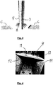
- One of the prototypes designed during the development of the invention had a single wall collection cap 4' (see the CFD modelling results of the collection efficiency in Figure 2 ).
- Another version of the suction cap 4 had double walls (see Figure 3 ) where the suction velocity between the double walls is significantly higher than in the centre. Thicker lines indicate higher suction rates.
- the suction for the DPS that is introduced through the dedicated duct 2 may preferably be connected retrofit to an existing feeder, or alternatively it could also be part of a new assembly replacing an existing feeder.
- the alumina may be feed from a fluidised feeder but also mechanical feeders.
- the gas When the gas is drawn through the duct 2, it will be collected into a main duct/manifold on the pot superstructure conveying gas from all feed points (not shown).
- the gas is from this transition points transported to the fume treatment systems (i.e. Fluoride recovery, and SO 2 removal) and introduced from there to any commercial CO 2 scrubbing system able to handle the actual concentrations of CO 2 or as input to combustion systems such as gas turbines, coal power plants or biomass combustion plant.
- the main collection duct for DPS points on the superstructure can be closed, and the main ducts in the pot superstructure is activated to support pot tending suction (PTS) from the pot (i.e. increasing the pot suction volume 2-4 times higher than normal.
- PTS pot tending suction
- the up-concentrated process gas is hotter than normal which makes it suitable for heat recovery.
- the warmer gas may damage the superstructure and electronics placed there.
- One way to solve this new challenge is to thermally insulate the components of the gas-collection systems within the superstructure and to the place where the heat recovery can take place outside the cell.
- Another alternative can be to arrange the gas collection caps and its corresponding ducting with some space with regard to other installations inside the superstructure of the cell.
- Process gases from several cells can be connected to the same heat recovery unit.
- the process gas is then sent for classical fume treatment, removing dust, HF and SO 2 .
- the flue gas might has to be purified sufficiently not to damage these process steps.
- the main features of one embodiment of the present invention consist in the integration of the point suction system with the alumina point feeder having a crust breaker.
- the step forward caused by the DPS is changed composition and increased temperature of the collected process gas.
- the gas collected by the DPS will contain much less "false air” and consequently have higher concentration of hazardous gases (Fluoride, SO x , and CO 2 ), This will ease the fluoride recovery and SO x removal.
- the aim is to increase the concentration of CO 2 to such a level that commercial available CO 2 scrubbing technologies can be utilised to remove it. Also, because of the smaller amount of air and installation straight above the feeding points the collected off-gas has increased temperature compared to the regular process gas, which increases the potential for heat exchange.
- process gas collection cap could be customised for any type of point feeder, and also be arranged in the vicinity of such feeder without being an integrated part of it.
- the suction in duct 2 in figure 1 is split into two independent suction flows that can be regulated, where the suction from the space 11 between the inner- and outer walls 14, 13, and the suction at the inside 12 of the cap 4 can be independently regulated. See also Fig. 4 .
- the inner wall 14 of the suction cap 4 can be both solid and perforated, i.e. provided with holes or not (not shown).
- the walls of the suction cap 4 can be angled outwards in such a way that the suction velocity vector can be aimed in any angle between 0-180 degrees downwards towards the crust.
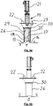
- Fig. 5a it is disclosed, in a cross sectional view, a second embodiment of a DPS, integrated with a point feeder (PF).
- PF point feeder
- an inner wall 28 shaped as a rectangular sleeve
- an outer wall 26 also shaped as a rectangular sleeve.
- the space between the inner and outer walls defines a suction space between these two walls, with inlet 15.
- the inner wall extends closer towards the crust than outer wall, and has suction inlet 16.
- Fig. 5b discloses in a side view the DPS as shown in Fig. 5a , rotated 90 degrees about its length axis.
- the outer wall 26, outlet 22 and 22' and a manifold plate 30 In this view there is shown the outer wall 26, outlet 22 and 22' and a manifold plate 30.
- the manifold plate is shown in more detail in an enlarged view, in Fig. 5c .
- the purpose of the manifold plate is to distribute the suction through outlet 22, 22' evenly into the space between the outer and inner walls. This is achieved by the arrangement of appropriate openings, O, O', O", O"' or slots through the plate.
- the plate has further openings for the alumina feed tube 23' and one stem of the point feeder PF.
- the lower part of the outer wall 26 may be provided with a diverging deflector (not shown).
- the deflector can be represented by a plate shaped part at all sides of the wall, and preferably having an angle ⁇ with regard to the horizontal plane. The purpose of the deflector is to assist the guiding of the flow of gases that is sucked into the gas cap.
- the angle ⁇ may preferably be of magnitude 30 - 60 °.
- a dust trap 29 in the inner part of the cap to avoid alumina and other particular constituents to follow the sucked off gas further into the gas evacuating system.
- the dust trap in such an embodiment can be represented by one or more slots 29 in the inner wall, i.e. the wall dividing the space between the double walls from the inner space of the suction cap.
- the slot is arranged near the top wall of the inner space in the cap, and in such manner that when suction is applied to the annular space, there will be a suction of gas through said slot.
- the effective gas flow opening of the slots can be designed in a manner where a suction in the space between the outer- and inner walls also will generate an appropriate suction inside the space defined by the inner wall, thus defining a relationship between the suction rate of inlet 15 versus inlet 16.
- the cross sectional area between the inner wall and the outer wall is increasing downstream a flow from the second inlet 15, thus reducing gas velocity.
- the suction cap is preferably placed at a distance from the crust allowing the anodes to pass beneath it during anode change.
- the cap is placed at a minimum distance to the crust depending on the suction rate.
- the distance is in order 10 to 1000 mm.
- the distance has to take into account the pickup velocity for alumina/anode cover material (ACM) which is in order of 7 metres per second, hence the said distance between the cap and the top of the crust should ensure that this level of velocities at the surface of the crust is not reached.
- ACM alumina/anode cover material
- This embodiment of DPS is designed to separate by physical measures the hot gas to be sucked off and the technical parts of the crust breaker as much as possible, to induce as little thermal stress as possible to vital parts of the crust breaker.
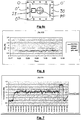
- Fig. 6 there is disclosed a diagram that shows the CO 2 concentration in a cell with traditional flue gas collection from inside the cell superstructure.
- Fig. 7 there is disclosed a diagram that shows the CO 2 concentration under varying conditions from "normal” to the left, to “pure DPS collection “to the right.
- Fig. 8 is a diagram that shows a schematic flow pattern in a cell, based upon five DPS units in the cell, seen from above. The arrows indicate the gas flow pattern above the crust, which is clearly directed towards the individual suction points.
- Fig. 9 there is shown the pressure distribution / gas flow in an electrolysis cell of commonly known type with evacuation "E" of process gas in the top of the cells' superstructure.
- evacuation "E” evacuation of process gas
- the cell is in a normal operation modus of a cell with closed superstructure, and all lids closed.
- Fig. 10 there is shown a pressure distribution in an electrolysis cell with evacuation "E" of process gas in accordance with the present invention by means of five DPS units and with no suction in the top of the superstructure.
- the cell is in a normal operation modus of a cell with closed superstructure.
- CO 2 capture and storage in accordance with the present invention can in one embodiment be performed in the following steps:
Landscapes
- Chemical & Material Sciences (AREA)
- Engineering & Computer Science (AREA)
- Chemical Kinetics & Catalysis (AREA)
- Electrochemistry (AREA)
- Materials Engineering (AREA)
- Metallurgy (AREA)
- Organic Chemistry (AREA)
- Electrolytic Production Of Metals (AREA)
- Treating Waste Gases (AREA)
- Manufacture And Refinement Of Metals (AREA)
- Sampling And Sample Adjustment (AREA)
Description
- The present invention relates to a method and a device for collection off gases in an electrolysis cell, in particular a cell for aluminium production.
- In all modern electrolysis cells for aluminium production having prebaked anodes the superstructure above the cell has several individual point feeders connected to the cell superstructure. The gas collection system has several suction points distributed along the process gas duct, located in the top of the superstructure, but as a separate system adjacent to the alumina feeding system. Since at least one anode normally has to be replaced by a new anode every day, modern prebake cells has a superstructure with many lids covering the area between the cathode and the gas skirt located just below the anode beam to prevent the flue gases from entering the potroom. In order to prevent this pollution one normally needs negative pressure (sub atmospheric) inside the cell superstructure and large quantities of air is sucked through these gaps and into the gas suction system together with the flue gases for further treatment, today fluoride recovery and in some cases sulphur removal (purification).
- The air entering the inside the superstructure, also provides air cooling of the upper part of the cell with its installed equipment (pneumatical-, electrical- and electronical- equipment). During anode replacements one needs to remove some of the lids. To prevent the flue gases from entering the potroom, and protect the operators from exposure, efficient flue gas collection can be obtained during this operation by increasing the suction volume significantly by setting the cell into Pot Tending Suction (PTS) mode for instance via a separate suction string. By flipping a valve, the gas suction can change from normal to PTS, and the increased suction volume enables handling the anode replacements with several lids removed from the cell without any flue gases entering the potroom, i.e maintaining the negative pressure inside the cell super structure.
- Feeding alumina to an electrolysis cell was performed more than a century ago by manually breaking the top crust of alumina and feeding alumina powder to the cell. The crust breakage was later done by a crust breaking wheel, than a crust breaker beam and finally an electronically controlled point crust breaker, which is being installed at basically all new smelters being built. Hence, point feeding is therefore considered state of the art.
- The production of aluminium also gives effluents, mainly CO2 with traces of CO, but also significant amounts of HF and SO2. Such effluents leave the electrolytic process through one layer of solidified crust above the electrolyte, through feeding holes but also through the crust itself. Modern smelters remove most of the HF and SO2 before the effluents are released to the atmosphere, but not CO2. In order to remove all the effluents being released from the cell and to cool the cell properly, the standard suction design involves several suction points along the main gas ducts situated approximately one meter from the top crust. These suction points suck in a lot of false air from gaps and joints in the cell's superstructure keeping a negative pressure inside the top lids to ensure capture of all the effluents released from the cell. The gas collected is comfortably cold for the superstructure (100-150°C), and the off-gases are strongly diluted by the false air.
- Up until today there has not been so much focus on CO2 scrubbing since it is a part of a natural circle, but the recent focus on how CO2 impacts the climate has changed the focus. The design limitation of modern electrolysis cells for CO2 capturing and sequestration is the low concentration of CO2 in the process gas, which typically is less than 1%. To remove low-concentration CO2 is both challenging and expensive thus has not been found published anywhere in the public literature. The cost of CO2 sequestration generally decreases with increasing CO2 concentration in the flue gas.
- The present invention generally relates to gas collection, preferably with an alumina feeder integrated. The invention relates to a method of collection of concentrated process gas for further treatment. In addition this device enables collection of process gas with enough elevated temperatures suitable for heat-recovery, such as flue gas that has a temperature of more than 100°C, preferably more than 150°C.
- In
WO 2006/009459 there is described a method and equipment for heat recovery from exhaust gas from a process plant, for instance process gas from an electrolysis plant for the production of aluminium. This type of technology can advantageously be combined with the present invention. - Various industrial processes produce process gases that can be contaminated by particles, dust and other species that can cause fouling in energy recovery equipment. Such fouling will imply reduced efficiency, and may require extensive maintenance such as cleaning of the surfaces exposed to the gas flow. Process gas may, before it is cleaned, contain dust and/or particles that will form deposits on the heat recovery equipment and thus reduce the efficiency of the heat recovery to an undesired low level. Thus energy recovery units are normally placed downstream a gas cleaning plant, after the gas has been cleaned.
- With respect to optimising the energy recovery, it is of interest to arrange the recovery units as close to the industrial process as possible, where the energy content in the process gas is at its maximum. This implies that the energy recovery units have to be arranged upstream the gas cleaning plant, because such plants are localised relatively distant to the industrial process. For example, process gas from an aluminium electrolysis reduction cell contains large amounts of energy at a relatively low temperature level. This energy is currently utilized only to a small extent, but it can be used for heating purposes, process purposes and power production if technically and economically acceptable solutions for heat recovery are established. The temperature level achieved in the heated fluid is decisive to the value and usefulness of the recovered thermal energy. The heat should therefore be extracted from the process gas at as high a process gas temperature as possible.
- Cooling the process gas will contribute to reduced gas flow rate and pressure drop, with reduced fan power as a consequence. The largest reduction in pressure drop is achieved by cooling the process gas as close to the aluminium cells as possible.
- The energy content of the process gas can be recovered in a heat exchanger (heat recovery systems) in which the process gas gives off heat (is cooled) to another fluid suitable for the application in question. In principle, the heat recovery system can be located:
- upstream of the cleaning process - where the heat recovery system must operate with a gas containing particles
- downstream of the cleaning process - where polluted components and particles in the gas have been removed,
- In the electrolysis cell itself.
- As the cleaning processes available today operate most optimal at a low temperature level, energy recovery is, in practice, relevant only for the alternative where the heat recovery system is located upstream of the cleaning process. This means, in practice, that the heat recovery system must be able to operate with hot gas containing particles.
- Cooling of the raw gas upstream the fans in combination with heat recovery is a solution that will reduce both the process gas volume flow rate and the pressure drop in channel system and gas cleaning plant. The suction can thereby be increased without the need of changing the dimensions of channels and gas cleaning plant.
- The heat recovered from the process gas is available as process heat for various heating and processing purposes, like CO2 sequestration.
- The present suction device for gas collection is able to obtain an efficient collection of the flue gases produced in the cell without alumina or anode cover material (ACM) entering the suction device. In the combination with a point feeder this gives a compact design.
-
US Patent 4,770,752 from 1988 describes a system where the gas collection cap is placed in contact with the crust in correspondence of a hole provided in the crust. The purpose of this invention is to collect the flue gases from the cell for purification of fluoride components by alumina and thereafter return the alumina and the fluorides to the cell again by a separate alumina feeder. CO2 scrubbing and heat recovery are not mentioned except from preheating the alumina. This invention has a limitation with respect to maintenance and possible damages occurring during anode replacements since the cap is situated so close to the anodes and the crust. There is no indication of any plant which utilised this invention, supporting the said drawbacks. -
JP Patent 57174483 from 1981 -
US describes a system where a cap is placed in contact with the crust in correspondence of a hole provided in the crust. The purpose of this invention is to collect the flue gases from the cell for purification of fluorine components by alumina situated close to the cell and thereafter feed the alumina and said components directly back into the same cell from which they have been emitted.Patent 4, 770, 752 from 1988 -
US Patent 5,968,334 describes removal of at least one of the gases CF4 and C2F6 from the flue gases from an electrolysis cell using a membrane. -
WO 01/36716 - The removal of process gas is made by openings arranged in the upper part of the superstructure, and in standardized mode a certain amount of air from the surroundings is allowed to enter into the superstructure due to the underpressure inside it. As one or more covers are opened or removed an increased amount of process gas is removed to ensure that as little process gas as possible is allowed to leak out of the superstructure to the surroundings. It is also proposed to install a central flow director to enhance the flow pattern in situations where covers are opened or removed.
- The present invention relates further to the principles of Distributed Pot Suction (DPS) where one can combine feeding the raw material alumina to the cell and at the same time extract a more CO2-concentrated flue gas from a hole in the top crust in the cell than what is standard procedure in the aluminium industry today. However, the suction can also be arranged at other places above the crust in the cell, if appropriate.
- The four net effects one obtains regarding the flue gas are:
- 1. Less total volume of gas removed from the cell with the potential to reduce the overall Fume Treatment Plants/ Centre (FTP/FTC) or Gas Treatment Centre (GTC).
- 2. As a consequence of
point 1 the process gas collected will be increased in temperature more than before and therefore more suitable for heat recovery. - 3. Suction of less "false air" into the gas collection chambers increases the concentration of CO2 in the off-gas significantly, enabling CO2 capture and sequestration with standard technologies used for CO2 capture from power plants.
- 4. Improvements of the gas flow inside the superstructure
- These and further advantages are achieved by a device for collection of hot gas from an electrolysis process producing metals in a cell, comprising a collection cap located above a gas evolving area, where the collection cap is connected to a gas evacuating system that generates suction flow, characterised in that the gas collection cap has at least two inlets for the gas to be collected, where one first inner inlet is surrounded by a second inlet.
- The invention further relates to a method for collection of hot gas from an electrolysis process in a cell that among other gases evolves CO2gas, by using said device, characterised in that the gas is collected in close vicinity of a crust through which the gas evolves so that the composition of the collected process gas includes at least 0,5-10% CO2.
- In the following, the invention shall be further explained by examples and Figures where:
- Fig. 1
- discloses one embodiment of a distributed pot suction (DPS) device in accordance with the invention,
- Fig. 2
- discloses a fluid dynamic model of the flue gas collection from a suction device comprising a cap with a single wall design,
- Fig. 3
- discloses a fluid dynamic model of the flue gas collection from a suction device comprising a cap with a double wall design,
- Fig. 4
- shows (in part) a picture of a double wall collection cap seen from underneath,
- Fig. 5a
- discloses in a cross sectional view, a second embodiment of a DPS,
- Fig. 5b
- discloses in a side view the DPS shown in
Fig. 5a , rotated 90 degrees about its length axis, - Fig. 5c
- discloses in an enlarged view, a distributor plate for the DPS shown in
Fig. 5a and 5b , - Fig. 6
- discloses a diagram showing the CO2 concentration in a cell with traditional flue gas collection from inside the cell superstructure,
- Fig. 7
- discloses a diagram that shows the CO2 concentration under varying conditions from "normal" to the left, to "pure DPS collection "to the right,
- Fig. 8
- discloses a schematic a gas flow pattern in the superstructure of a cell operated with five DPS units, seen from above,
- Fig. 9
- discloses a diagram that shows the pressure distribution / gas flow in an electrolysis cell with suction out of top of the cells superstructure,
- Fig. 10
- discloses a diagram that shows the pressure distribution / gas flow in an electrolysis cell with suction in accordance with the DPS present invention and with no suction in the top of the superstructure.
- To obtain maximum gas collection from the distributed pot suction device (DPS), one can design the collection cap in many ways. One of the prototypes designed during the development of the invention had a single wall collection cap 4' (see the CFD modelling results of the collection efficiency in
Figure 2 ). Another version of thesuction cap 4 had double walls (seeFigure 3 ) where the suction velocity between the double walls is significantly higher than in the centre. Thicker lines indicate higher suction rates. - This extra suction creates an artificial "air wall", which gives a more efficient flue gas collection from the hole "H" in the crust "C", and decreases disturbance from cross flows. One can also equip the DPS with pressurised air, and blow air through this joint, with the penalty of using more of the compressed air in the pot room for this application. In the Figs, the
reference numeral 7 indicates the crust breaker bar. - A functional description of DPS (Distributed Pot Suction) combined with a point feeder follows:
- In
Figure 1 a pneumatic cylinder of a crust breaker is indicated atreference sign 1, the breaker is attached to the DPS main parts.In the Figure there is showncollection cap 4,alumina feeding tube 3,gas suction duct 5 with avalve 6. At the other side of the valve there is shown aduct 2. - During operation the normal gas flow on the pot superstructure is relayed trough the DPS, a DPS point is placed in each of the feeding points of the pot. The suction for the DPS that is introduced through the
dedicated duct 2 may preferably be connected retrofit to an existing feeder, or alternatively it could also be part of a new assembly replacing an existing feeder. The alumina may be feed from a fluidised feeder but also mechanical feeders. - When the gas is drawn through the
duct 2, it will be collected into a main duct/manifold on the pot superstructure conveying gas from all feed points (not shown). The gas is from this transition points transported to the fume treatment systems (i.e. Fluoride recovery, and SO2 removal) and introduced from there to any commercial CO2 scrubbing system able to handle the actual concentrations of CO2 or as input to combustion systems such as gas turbines, coal power plants or biomass combustion plant. - When the pot is to be serviced, the main collection duct for DPS points on the superstructure can be closed, and the main ducts in the pot superstructure is activated to support pot tending suction (PTS) from the pot (i.e. increasing the pot suction volume 2-4 times higher than normal.
- The up-concentrated process gas is hotter than normal which makes it suitable for heat recovery. On the other hand, the warmer gas may damage the superstructure and electronics placed there. One way to solve this new challenge is to thermally insulate the components of the gas-collection systems within the superstructure and to the place where the heat recovery can take place outside the cell.
- Another alternative can be to arrange the gas collection caps and its corresponding ducting with some space with regard to other installations inside the superstructure of the cell.
- Process gases from several cells can be connected to the same heat recovery unit. The process gas is then sent for classical fume treatment, removing dust, HF and SO2. Depending on whether one connect the flue gas to another process as combustion air or directly to a CO2 scrubber unit, the flue gas might has to be purified sufficiently not to damage these process steps.
- The main features of one embodiment of the present invention consist in the integration of the point suction system with the alumina point feeder having a crust breaker. The step forward caused by the DPS is changed composition and increased temperature of the collected process gas. The gas collected by the DPS will contain much less "false air" and consequently have higher concentration of hazardous gases (Fluoride, SOx, and CO2), This will ease the fluoride recovery and SOx removal. The aim is to increase the concentration of CO2 to such a level that commercial available CO2 scrubbing technologies can be utilised to remove it. Also, because of the smaller amount of air and installation straight above the feeding points the collected off-gas has increased temperature compared to the regular process gas, which increases the potential for heat exchange.
- It should be clear for any person skilled in the art that the process gas collection cap could be customised for any type of point feeder, and also be arranged in the vicinity of such feeder without being an integrated part of it.
- The suction in
duct 2 infigure 1 is split into two independent suction flows that can be regulated, where the suction from thespace 11 between the inner- andouter walls 14, 13, and the suction at the inside 12 of thecap 4 can be independently regulated. See alsoFig. 4 . The inner wall 14 of thesuction cap 4 can be both solid and perforated, i.e. provided with holes or not (not shown). Furthermore, the walls of thesuction cap 4 can be angled outwards in such a way that the suction velocity vector can be aimed in any angle between 0-180 degrees downwards towards the crust. - In
Fig. 5a it is disclosed, in a cross sectional view, a second embodiment of a DPS, integrated with a point feeder (PF). - In this embodiment, there is shown an
inner wall 28 shaped as a rectangular sleeve, and anouter wall 26, also shaped as a rectangular sleeve. The space between the inner and outer walls defines a suction space between these two walls, with inlet 15. The inner wall extends closer towards the crust than outer wall, and hassuction inlet 16. Further, there is shown analumina feeding tube 23, 23',suction outlet 22,pneumatic cylinder 21 and a crust breaker (bar) 27. -
Fig. 5b discloses in a side view the DPS as shown inFig. 5a , rotated 90 degrees about its length axis. In this view there is shown theouter wall 26,outlet 22 and 22' and amanifold plate 30. The manifold plate is shown in more detail in an enlarged view, inFig. 5c . The purpose of the manifold plate is to distribute the suction throughoutlet 22, 22' evenly into the space between the outer and inner walls. This is achieved by the arrangement of appropriate openings, O, O', O", O"' or slots through the plate. The plate has further openings for the alumina feed tube 23' and one stem of the point feeder PF. - Further, the lower part of the
outer wall 26 may be provided with a diverging deflector (not shown). The deflector can be represented by a plate shaped part at all sides of the wall, and preferably having an angle β with regard to the horizontal plane. The purpose of the deflector is to assist the guiding of the flow of gases that is sucked into the gas cap. The angle β may preferably be of magnitude 30 - 60 °. - Further, there may be arranged a dust trap 29 (see
Fig. 5a ) in the inner part of the cap to avoid alumina and other particular constituents to follow the sucked off gas further into the gas evacuating system. The dust trap in such an embodiment can be represented by one ormore slots 29 in the inner wall, i.e. the wall dividing the space between the double walls from the inner space of the suction cap. Preferably, the slot is arranged near the top wall of the inner space in the cap, and in such manner that when suction is applied to the annular space, there will be a suction of gas through said slot. By this means gas containing particular materials and entering the inner space of the cap, will be accelerated and hit against the "roof" in the cap and fall down to the crust or feeder hole beneath the cap. - Further, the effective gas flow opening of the slots can be designed in a manner where a suction in the space between the outer- and inner walls also will generate an appropriate suction inside the space defined by the inner wall, thus defining a relationship between the suction rate of inlet 15 versus
inlet 16. - Preferably, the cross sectional area between the inner wall and the outer wall is increasing downstream a flow from the second inlet 15, thus reducing gas velocity.
- The suction cap is preferably placed at a distance from the crust allowing the anodes to pass beneath it during anode change. Advantageously, the cap is placed at a minimum distance to the crust depending on the suction rate. Preferably the distance is in order 10 to 1000 mm.
- The distance has to take into account the pickup velocity for alumina/anode cover material (ACM) which is in order of 7 metres per second, hence the said distance between the cap and the top of the crust should ensure that this level of velocities at the surface of the crust is not reached.
- This embodiment of DPS is designed to separate by physical measures the hot gas to be sucked off and the technical parts of the crust breaker as much as possible, to induce as little thermal stress as possible to vital parts of the crust breaker.
- In
Fig. 6 there is disclosed a diagram that shows the CO2 concentration in a cell with traditional flue gas collection from inside the cell superstructure. - In
Fig. 7 there is disclosed a diagram that shows the CO2 concentration under varying conditions from "normal" to the left, to "pure DPS collection "to the right. -
Fig. 8 is a diagram that shows a schematic flow pattern in a cell, based upon five DPS units in the cell, seen from above. The arrows indicate the gas flow pattern above the crust, which is clearly directed towards the individual suction points. - By this means it is possible to withdraw most of the process gases evolved in the cell. In addition, by extracting this rather huge volume of gases just above the crust where the caps are located, the global flow pattern inside the superstructure of the cell will be influenced in a positive manner. This will be further explained with reference to
Figs. 9 and10 . - In
Fig. 9 , there is shown the pressure distribution / gas flow in an electrolysis cell of commonly known type with evacuation "E" of process gas in the top of the cells' superstructure. In such arrangement there will be a chimney effect that, together with the fact that the gas is sucked off in the top of the cell, dominates the flow pattern inside the cell. - In the figure, the cell is in a normal operation modus of a cell with closed superstructure, and all lids closed.
- In
Fig. 10 there is shown a pressure distribution in an electrolysis cell with evacuation "E" of process gas in accordance with the present invention by means of five DPS units and with no suction in the top of the superstructure. As inFig. 9 , the cell is in a normal operation modus of a cell with closed superstructure. - The CO2 capture and storage in accordance with the present invention can in one embodiment be performed in the following steps:
- 1) Cell CO2 production
- 2) Collecting flue gas with high CO2 content
- 3) Heat recovery of said gas
- 4) Pre-scrubbing
- 5) Gas to other processes and/or feeding gas to CO2 scrubber
- 6) Purified gas led out of scrubber, CO2 led to a pressurizing station
- 7) Liquified CO2 transported to storage.
Claims (25)
- A device for collection of hot gas from an electrolysis process producing metals in a cell, comprising a collection cap (4) located above a gas evolving area, where the collection cap (4) is connected to a gas evacuating system that generates suction flow,
characterised in that
the gas collection cap (4) has at least two inlets (11, 12; 15, 16) for the gas to be collected where one first inner inlet (12; 16) is surrounded by a second inlet (11; 15). - A device in accordance to claim 1,
characterised in that
the collection cap (4) is made of a double wall construction, one inner (14; 28) and one outer wall (13; 26), where the second inlet (11; 15) is represented by a defined space between the said two walls. - A device in accordance to claim 2,
characterised in that
the cross sectional area between the inner wall (14; 28) and the outer wall (13; 26) is increasing downstream a flow from the second inlet (11; 15), thus reducing gas velocity. - A device in accordance to claim 2
characterised in that
the inner wall (28) extends closer to the gas evolving area than the outer wall (26). - A device in accordance to claim 2
characterised in that
the inner wall (28) has at least one slot (29) in its upper part that allows gas to flow from the first inlet (16) to the space between the two walls. - A device in accordance to claim 3
characterised in that
the lower part of the outer wall (26) is diverging outwards with regard to the inner wall. - A device in accordance to claims 1-4,
characterised in that
the velocity of the gas flow through the first inlet (12; 16) is different to that of the second inlet (11; 15), and preferably lower. - A device in accordance to claim 1,
characterised in that
it is integrated into a point feeder (PF) provided with a crust breaker (27). - A device in accordance to claim 6,
characterised in that
the device is situated above one feeding hole (H) made by the point feeder crust breaker (27), preferably 10 - 1000 mm above the crust (C). - A device in accordance to claim 8 or 9,
characterised in that
the point feeder feeds material inside and/or close to the gas collection cap (4). - A device in accordance to claim 1
characterised in that
all the process gases can be collected through the device with proper suction efficiency without any other gas collection in the cell superstructure during normal operation. - A device in accordance to claim 1
characterised in that
the suction flow in the cap can run like normal during alumina feeding. - A device in accordance to claim 1
characterised in that
the suction flow in the cap can be blocked during alumina feeding. - A device in accordance to claim 1,
characterised in that:.
the hot gas collected can be used for heat recovery. - A device in accordance to claim 1
characterised in that
the hot gas collected can be purified to separate gases like HF, SO2, CO2 vapours and dust. - A device in according to claim 1
characterised in that
the shape of the collection cap (4) is either circular, elliptical, quadratic or rectangular. - A device in according to claim 1
characterised in that
the shape of the collection cap (4) is optimised for the necessary suction volume, such as conical. - A device in according to claim 1
characterised in that
it can be combined with a separate gas collection system used during standard operations like anode replacements and metal tapping. - A device in according to claim 1
characterised in that:the electrolysis process is producing aluminium or other metals. - A device in according to claim 1
characterised in that
the device is connected with thermally insulated flue gas collection system/ tubes within the cell superstructure. - A method for collection of hot gas from an electrolysis process in a cell, that among other gases evolves CO2 gas, by using the device as defined in one or more preceding claims 1-20,
characterised in that
the gas is collected in close vicinity of a crust (C) through which the gas evolves so that the composition of the collected process gas includes at least 0,5-10% CO2. - A method in accordance with claim 21,
characterised in that
the gas is collected in close vicinity of a feeding hole ( H) in the crust ( C ), to withdraw most of the process gases evolved in the cell. - A method in accordance with claim 21,
characterised in that
the hot gas has a temperature of more than 100°C, preferably more than 150°C. - A method in accordance with claim 21,
characterised in that
heat is extracted from the hot gas by appropriate heat exchange means, such as an exhaust gas heat exchanger. - A method in accordance with claim 21,
characterised in that
the hot gas is separated downstream into a CO2 enriched component.
Applications Claiming Priority (2)
| Application Number | Priority Date | Filing Date | Title |
|---|---|---|---|
| NO20084014A NO332375B1 (en) | 2008-09-19 | 2008-09-19 | Spot feeder with integrated exhaust collection as well as a method for exhaust collection |
| PCT/NO2009/000324 WO2010033037A1 (en) | 2008-09-19 | 2009-09-17 | A device for collection of hot gas from an electrolysis process, and a method for gas collection with said device |
Publications (3)
| Publication Number | Publication Date |
|---|---|
| EP2337879A1 EP2337879A1 (en) | 2011-06-29 |
| EP2337879A4 EP2337879A4 (en) | 2014-09-24 |
| EP2337879B1 true EP2337879B1 (en) | 2016-12-14 |
Family
ID=42039723
Family Applications (1)
| Application Number | Title | Priority Date | Filing Date |
|---|---|---|---|
| EP09814835.6A Active EP2337879B1 (en) | 2008-09-19 | 2009-09-17 | A device for collection of hot gas from an electrolysis process, and a method for gas collection with said device |
Country Status (10)
| Country | Link |
|---|---|
| EP (1) | EP2337879B1 (en) |
| CN (1) | CN102197164B (en) |
| AU (1) | AU2009292735B2 (en) |
| BR (1) | BRPI0918929B1 (en) |
| CA (1) | CA2737240C (en) |
| EA (1) | EA019844B1 (en) |
| NO (2) | NO332375B1 (en) |
| NZ (1) | NZ591699A (en) |
| WO (1) | WO2010033037A1 (en) |
| ZA (1) | ZA201102085B (en) |
Cited By (5)
| Publication number | Priority date | Publication date | Assignee | Title |
|---|---|---|---|---|
| WO2018137025A1 (en) * | 2017-01-24 | 2018-08-02 | Rio Tinto Alcan International Limited | Device for supplying alumina to an electrolytic cell |
| NO20200539A1 (en) * | 2017-11-20 | 2020-05-08 | Obshchestvo S Ogranichennoy Otvetstvennost'yu "Obedinennaya Kompaniya Rusal "Inzhenerno-Tekhnologich | Device for collecting and removing gases in an aluminum electrolysis cell |
| NO20190343A1 (en) * | 2019-03-14 | 2020-09-15 | Norsk Hydro As | Arrangement for collection of hot gas from an electrolysis process, and a method for such gas collection |
| WO2023206892A1 (en) * | 2022-04-29 | 2023-11-02 | 沈阳北冶冶金科技有限公司 | Method for collecting high-temperature anode gas of aluminum electrolysis cell |
| WO2025189287A1 (en) * | 2024-03-12 | 2025-09-18 | Elysis Limited Partnership | Modular feed kit assembly for electrolytic cell |
Families Citing this family (9)
| Publication number | Priority date | Publication date | Assignee | Title |
|---|---|---|---|---|
| FR2959137B1 (en) * | 2010-04-23 | 2015-07-03 | Solios Environnement | SYSTEM AND METHOD FOR THE TREATMENT WITH CONCENTRATION OF SMOKE AND GAS PRODUCED BY AN ELECTROLYTIC TANK IN THE MANUFACTURE OF ALUMINUM |
| CN102776531A (en) * | 2011-05-09 | 2012-11-14 | 贵阳铝镁设计研究院有限公司 | Burner gas collection apparatus of aluminum electrolysis cell |
| CN102628170A (en) * | 2011-10-18 | 2012-08-08 | 高伟 | Embedding-type alumina feeding device |
| CN102628171B (en) * | 2012-04-26 | 2014-09-10 | 北京世纪源博科技股份有限公司 | Aluminum electrolytic cell electrolytic gas thermal conversion devices |
| NZ727341A (en) | 2014-06-09 | 2018-07-27 | Bechtel Mining & Metals Inc | Integrated gas treatment |
| WO2019041006A1 (en) * | 2017-08-31 | 2019-03-07 | Caete Engenharia Ltda | Apparatus for feeding and preheating the alumina |
| RU186730U1 (en) * | 2018-03-05 | 2019-01-31 | Общество с ограниченной ответственностью "Объединенная Компания РУСАЛ Инженерно-технологический центр" | DEVICE FOR REMOVING GASES OF ALUMINUM ELECTROLYZER |
| US12509788B2 (en) * | 2019-03-20 | 2025-12-30 | Elysis Limited Partnership | System and method for collecting and pre-treating process gases generated by an electrolysis cell |
| CN116815251B (en) * | 2023-07-10 | 2024-08-06 | 中南大学 | A gradient heat-insulating sealed aluminum electrolytic cell |
Family Cites Families (13)
| Publication number | Priority date | Publication date | Assignee | Title |
|---|---|---|---|---|
| US3714002A (en) * | 1970-09-02 | 1973-01-30 | Reynolds Metals Co | Alumina reduction cell and improved anode system therein |
| US3729399A (en) * | 1971-07-13 | 1973-04-24 | Reynolds Metals Co | Gas control method and apparatus |
| FR2262700B1 (en) * | 1974-02-28 | 1978-12-29 | Pechiney Aluminium | |
| JPS57174483A (en) | 1981-04-17 | 1982-10-27 | Sumitomo Light Metal Ind Ltd | Method and device for continuous measurement of current efficiency of aluminum electrolyzing cell |
| SU1025756A1 (en) * | 1981-11-26 | 1983-06-30 | Всесоюзный Научно-Исследовательский И Проектный Институт Алюминиевой,Магниевой И Электродной Промышленности | Apparatus for catching gases released in producing aluminium by electrolysis |
| IT1196487B (en) * | 1986-07-15 | 1988-11-16 | Techmo Car Spa | PROCEDURE FOR DEPURING GASES EMITTED BY ELECTROLYSIS OVENS FOR THE PRODUCTION OF ALUMINUM AND RELATED EQUIPMENT |
| US5814127A (en) | 1996-12-23 | 1998-09-29 | American Air Liquide Inc. | Process for recovering CF4 and C2 F6 from a gas |
| NO310730B1 (en) * | 1999-11-17 | 2001-08-20 | Norsk Hydro As | Method and apparatus for operation of electrolysis cell |
| NO20010927D0 (en) * | 2001-02-23 | 2001-02-23 | Norsk Hydro As | Method and apparatus for making metal |
| RU2218453C1 (en) * | 2002-05-06 | 2003-12-10 | Открытое акционерное общество "Всероссийский алюминиево-магниевый институт" | Apparatus to collect and remove gases of aluminum electrolyzer |
| NO20043150D0 (en) | 2004-07-23 | 2004-07-23 | Ntnu Technology Transfer As | "Heat recovery method and equipment" |
| DE102005033912B3 (en) * | 2005-07-20 | 2006-10-26 | Tyco Electronics Pretema Gmbh & Co.Kg | Electric contact housing duct comprises a housing element containing an embedded conductor element with a sealing region formed between the housing element and conductor element |
| RU2316620C1 (en) * | 2006-04-18 | 2008-02-10 | Общество с ограниченной ответственностью "Русская инжиниринговая компания" | Apparatus for collecting and removing gases from aluminum cell |
-
2008
- 2008-09-19 NO NO20084014A patent/NO332375B1/en unknown
-
2009
- 2009-09-17 AU AU2009292735A patent/AU2009292735B2/en active Active
- 2009-09-17 EA EA201100508A patent/EA019844B1/en not_active IP Right Cessation
- 2009-09-17 CA CA2737240A patent/CA2737240C/en active Active
- 2009-09-17 WO PCT/NO2009/000324 patent/WO2010033037A1/en not_active Ceased
- 2009-09-17 BR BRPI0918929-7A patent/BRPI0918929B1/en active IP Right Grant
- 2009-09-17 NZ NZ591699A patent/NZ591699A/en unknown
- 2009-09-17 CN CN200980142128.9A patent/CN102197164B/en active Active
- 2009-09-17 EP EP09814835.6A patent/EP2337879B1/en active Active
-
2011
- 2011-03-18 ZA ZA2011/02085A patent/ZA201102085B/en unknown
- 2011-03-18 NO NO20110421A patent/NO349269B1/en unknown
Non-Patent Citations (1)
| Title |
|---|
| None * |
Cited By (7)
| Publication number | Priority date | Publication date | Assignee | Title |
|---|---|---|---|---|
| WO2018137025A1 (en) * | 2017-01-24 | 2018-08-02 | Rio Tinto Alcan International Limited | Device for supplying alumina to an electrolytic cell |
| EA037235B1 (en) * | 2017-01-24 | 2021-02-25 | Рио Тинто Алкан Интернэшнл Лимитед | Device for supplying alumina to an electrolytic cell |
| NO20200539A1 (en) * | 2017-11-20 | 2020-05-08 | Obshchestvo S Ogranichennoy Otvetstvennost'yu "Obedinennaya Kompaniya Rusal "Inzhenerno-Tekhnologich | Device for collecting and removing gases in an aluminum electrolysis cell |
| NO20190343A1 (en) * | 2019-03-14 | 2020-09-15 | Norsk Hydro As | Arrangement for collection of hot gas from an electrolysis process, and a method for such gas collection |
| WO2020182776A1 (en) | 2019-03-14 | 2020-09-17 | Norsk Hydro Asa | Arrangement for collection of hot gas from an electrolysis process, and a method for such gas collection |
| WO2023206892A1 (en) * | 2022-04-29 | 2023-11-02 | 沈阳北冶冶金科技有限公司 | Method for collecting high-temperature anode gas of aluminum electrolysis cell |
| WO2025189287A1 (en) * | 2024-03-12 | 2025-09-18 | Elysis Limited Partnership | Modular feed kit assembly for electrolytic cell |
Also Published As
| Publication number | Publication date |
|---|---|
| NO332375B1 (en) | 2012-09-10 |
| EA019844B1 (en) | 2014-06-30 |
| EP2337879A1 (en) | 2011-06-29 |
| NO20084014L (en) | 2010-03-22 |
| CN102197164A (en) | 2011-09-21 |
| EP2337879A4 (en) | 2014-09-24 |
| NO349269B1 (en) | 2025-11-24 |
| NO20110421A1 (en) | 2011-03-18 |
| NZ591699A (en) | 2013-06-28 |
| CA2737240A1 (en) | 2010-03-25 |
| EA201100508A1 (en) | 2011-10-31 |
| AU2009292735A1 (en) | 2010-03-25 |
| CA2737240C (en) | 2016-07-05 |
| BRPI0918929A2 (en) | 2015-12-01 |
| WO2010033037A1 (en) | 2010-03-25 |
| CN102197164B (en) | 2014-07-09 |
| ZA201102085B (en) | 2011-11-30 |
| BRPI0918929B1 (en) | 2019-04-09 |
| AU2009292735B2 (en) | 2015-08-27 |
Similar Documents
| Publication | Publication Date | Title |
|---|---|---|
| CA2737240C (en) | A device for collection of hot gas from an electrolysis process, and a method for gas collection with said device | |
| RU2436872C2 (en) | Entrapping system and method of emissions from electrolysis unit | |
| EP2407228B1 (en) | Gas cleaning unit and method for cleaning gas | |
| RU2559604C2 (en) | Method of ventilation of electrolyser for aluminium smelting | |
| CN107075608B (en) | Integrated Gas Handling | |
| CA3133373C (en) | Arrangement for collection of hot gas from an electrolysis process, and a method for such gas collection | |
| NO179182B (en) | Method for cleaning smoke emitted from electrolysis furnaces, and equipment for carrying out the process | |
| CN111981860B (en) | A Submerged Arc Furnace for Reusing Soot Sealing | |
| CN103382562A (en) | Recycled pot gas pot distribution | |
| NO20111050A1 (en) | Method and apparatus for enclosing cell gases in an electrolytic aluminum cell | |
| EA043551B1 (en) | DEVICE FOR COLLECTING HOT GAS FROM THE ELECTROLYSIS PROCESS AND METHOD FOR SUCH GAS COLLECTION | |
| CN109517606B (en) | Ventilation system of coke oven integral closed greenhouse | |
| EP2431499B1 (en) | Raw gas collection system | |
| BR112021015866B1 (en) | DUAL CHANNEL GAS COLLECTION SYSTEM FOR HOT GAS COLLECTION, AND METHOD FOR DUAL HOT GAS COLLECTION | |
| CN204006056U (en) | A kind of flue gas ash removal structure for ammonium tungstate heating boiler | |
| CN105154613A (en) | Converter dry-dedusting technology |
Legal Events
| Date | Code | Title | Description |
|---|---|---|---|
| PUAI | Public reference made under article 153(3) epc to a published international application that has entered the european phase |
Free format text: ORIGINAL CODE: 0009012 |
|
| 17P | Request for examination filed |
Effective date: 20110419 |
|
| AK | Designated contracting states |
Kind code of ref document: A1 Designated state(s): AT BE BG CH CY CZ DE DK EE ES FI FR GB GR HR HU IE IS IT LI LT LU LV MC MK MT NL NO PL PT RO SE SI SK SM TR |
|
| AX | Request for extension of the european patent |
Extension state: AL BA RS |
|
| DAX | Request for extension of the european patent (deleted) | ||
| A4 | Supplementary search report drawn up and despatched |
Effective date: 20140826 |
|
| RIC1 | Information provided on ipc code assigned before grant |
Ipc: C25C 3/14 20060101ALI20140820BHEP Ipc: C25C 3/22 20060101AFI20140820BHEP |
|
| GRAP | Despatch of communication of intention to grant a patent |
Free format text: ORIGINAL CODE: EPIDOSNIGR1 |
|
| INTG | Intention to grant announced |
Effective date: 20160915 |
|
| STAA | Information on the status of an ep patent application or granted ep patent |
Free format text: STATUS: GRANT OF PATENT IS INTENDED |
|
| GRAS | Grant fee paid |
Free format text: ORIGINAL CODE: EPIDOSNIGR3 |
|
| GRAA | (expected) grant |
Free format text: ORIGINAL CODE: 0009210 |
|
| STAA | Information on the status of an ep patent application or granted ep patent |
Free format text: STATUS: THE PATENT HAS BEEN GRANTED |
|
| AK | Designated contracting states |
Kind code of ref document: B1 Designated state(s): AT BE BG CH CY CZ DE DK EE ES FI FR GB GR HR HU IE IS IT LI LT LU LV MC MK MT NL NO PL PT RO SE SI SK SM TR |
|
| REG | Reference to a national code |
Ref country code: GB Ref legal event code: FG4D |
|
| REG | Reference to a national code |
Ref country code: CH Ref legal event code: EP |
|
| REG | Reference to a national code |
Ref country code: IE Ref legal event code: FG4D |
|
| REG | Reference to a national code |
Ref country code: AT Ref legal event code: REF Ref document number: 853663 Country of ref document: AT Kind code of ref document: T Effective date: 20170115 |
|
| REG | Reference to a national code |
Ref country code: DE Ref legal event code: R096 Ref document number: 602009043125 Country of ref document: DE |
|
| PG25 | Lapsed in a contracting state [announced via postgrant information from national office to epo] |
Ref country code: LV Free format text: LAPSE BECAUSE OF FAILURE TO SUBMIT A TRANSLATION OF THE DESCRIPTION OR TO PAY THE FEE WITHIN THE PRESCRIBED TIME-LIMIT Effective date: 20161214 |
|
| REG | Reference to a national code |
Ref country code: LT Ref legal event code: MG4D |
|
| REG | Reference to a national code |
Ref country code: NL Ref legal event code: MP Effective date: 20161214 |
|
| PG25 | Lapsed in a contracting state [announced via postgrant information from national office to epo] |
Ref country code: LT Free format text: LAPSE BECAUSE OF FAILURE TO SUBMIT A TRANSLATION OF THE DESCRIPTION OR TO PAY THE FEE WITHIN THE PRESCRIBED TIME-LIMIT Effective date: 20161214 Ref country code: SE Free format text: LAPSE BECAUSE OF FAILURE TO SUBMIT A TRANSLATION OF THE DESCRIPTION OR TO PAY THE FEE WITHIN THE PRESCRIBED TIME-LIMIT Effective date: 20161214 Ref country code: GR Free format text: LAPSE BECAUSE OF FAILURE TO SUBMIT A TRANSLATION OF THE DESCRIPTION OR TO PAY THE FEE WITHIN THE PRESCRIBED TIME-LIMIT Effective date: 20170315 Ref country code: NO Free format text: LAPSE BECAUSE OF FAILURE TO SUBMIT A TRANSLATION OF THE DESCRIPTION OR TO PAY THE FEE WITHIN THE PRESCRIBED TIME-LIMIT Effective date: 20170314 |
|
| REG | Reference to a national code |
Ref country code: AT Ref legal event code: MK05 Ref document number: 853663 Country of ref document: AT Kind code of ref document: T Effective date: 20161214 |
|
| PG25 | Lapsed in a contracting state [announced via postgrant information from national office to epo] |
Ref country code: HR Free format text: LAPSE BECAUSE OF FAILURE TO SUBMIT A TRANSLATION OF THE DESCRIPTION OR TO PAY THE FEE WITHIN THE PRESCRIBED TIME-LIMIT Effective date: 20161214 Ref country code: FI Free format text: LAPSE BECAUSE OF FAILURE TO SUBMIT A TRANSLATION OF THE DESCRIPTION OR TO PAY THE FEE WITHIN THE PRESCRIBED TIME-LIMIT Effective date: 20161214 |
|
| PG25 | Lapsed in a contracting state [announced via postgrant information from national office to epo] |
Ref country code: NL Free format text: LAPSE BECAUSE OF FAILURE TO SUBMIT A TRANSLATION OF THE DESCRIPTION OR TO PAY THE FEE WITHIN THE PRESCRIBED TIME-LIMIT Effective date: 20161214 |
|
| PG25 | Lapsed in a contracting state [announced via postgrant information from national office to epo] |
Ref country code: RO Free format text: LAPSE BECAUSE OF FAILURE TO SUBMIT A TRANSLATION OF THE DESCRIPTION OR TO PAY THE FEE WITHIN THE PRESCRIBED TIME-LIMIT Effective date: 20161214 Ref country code: EE Free format text: LAPSE BECAUSE OF FAILURE TO SUBMIT A TRANSLATION OF THE DESCRIPTION OR TO PAY THE FEE WITHIN THE PRESCRIBED TIME-LIMIT Effective date: 20161214 Ref country code: CZ Free format text: LAPSE BECAUSE OF FAILURE TO SUBMIT A TRANSLATION OF THE DESCRIPTION OR TO PAY THE FEE WITHIN THE PRESCRIBED TIME-LIMIT Effective date: 20161214 |
|
| PG25 | Lapsed in a contracting state [announced via postgrant information from national office to epo] |
Ref country code: IT Free format text: LAPSE BECAUSE OF FAILURE TO SUBMIT A TRANSLATION OF THE DESCRIPTION OR TO PAY THE FEE WITHIN THE PRESCRIBED TIME-LIMIT Effective date: 20161214 Ref country code: BG Free format text: LAPSE BECAUSE OF FAILURE TO SUBMIT A TRANSLATION OF THE DESCRIPTION OR TO PAY THE FEE WITHIN THE PRESCRIBED TIME-LIMIT Effective date: 20170314 Ref country code: SM Free format text: LAPSE BECAUSE OF FAILURE TO SUBMIT A TRANSLATION OF THE DESCRIPTION OR TO PAY THE FEE WITHIN THE PRESCRIBED TIME-LIMIT Effective date: 20161214 Ref country code: BE Free format text: LAPSE BECAUSE OF FAILURE TO SUBMIT A TRANSLATION OF THE DESCRIPTION OR TO PAY THE FEE WITHIN THE PRESCRIBED TIME-LIMIT Effective date: 20161214 Ref country code: AT Free format text: LAPSE BECAUSE OF FAILURE TO SUBMIT A TRANSLATION OF THE DESCRIPTION OR TO PAY THE FEE WITHIN THE PRESCRIBED TIME-LIMIT Effective date: 20161214 Ref country code: PL Free format text: LAPSE BECAUSE OF FAILURE TO SUBMIT A TRANSLATION OF THE DESCRIPTION OR TO PAY THE FEE WITHIN THE PRESCRIBED TIME-LIMIT Effective date: 20161214 Ref country code: PT Free format text: LAPSE BECAUSE OF FAILURE TO SUBMIT A TRANSLATION OF THE DESCRIPTION OR TO PAY THE FEE WITHIN THE PRESCRIBED TIME-LIMIT Effective date: 20170414 Ref country code: ES Free format text: LAPSE BECAUSE OF FAILURE TO SUBMIT A TRANSLATION OF THE DESCRIPTION OR TO PAY THE FEE WITHIN THE PRESCRIBED TIME-LIMIT Effective date: 20161214 |
|
| REG | Reference to a national code |
Ref country code: SK Ref legal event code: T3 Ref document number: E 23692 Country of ref document: SK |
|
| REG | Reference to a national code |
Ref country code: DE Ref legal event code: R097 Ref document number: 602009043125 Country of ref document: DE |
|
| REG | Reference to a national code |
Ref country code: FR Ref legal event code: PLFP Year of fee payment: 9 |
|
| PLBE | No opposition filed within time limit |
Free format text: ORIGINAL CODE: 0009261 |
|
| STAA | Information on the status of an ep patent application or granted ep patent |
Free format text: STATUS: NO OPPOSITION FILED WITHIN TIME LIMIT |
|
| 26N | No opposition filed |
Effective date: 20170915 |
|
| PG25 | Lapsed in a contracting state [announced via postgrant information from national office to epo] |
Ref country code: DK Free format text: LAPSE BECAUSE OF FAILURE TO SUBMIT A TRANSLATION OF THE DESCRIPTION OR TO PAY THE FEE WITHIN THE PRESCRIBED TIME-LIMIT Effective date: 20161214 |
|
| PG25 | Lapsed in a contracting state [announced via postgrant information from national office to epo] |
Ref country code: SI Free format text: LAPSE BECAUSE OF FAILURE TO SUBMIT A TRANSLATION OF THE DESCRIPTION OR TO PAY THE FEE WITHIN THE PRESCRIBED TIME-LIMIT Effective date: 20161214 |
|
| REG | Reference to a national code |
Ref country code: CH Ref legal event code: PL |
|
| GBPC | Gb: european patent ceased through non-payment of renewal fee |
Effective date: 20170917 |
|
| PG25 | Lapsed in a contracting state [announced via postgrant information from national office to epo] |
Ref country code: MC Free format text: LAPSE BECAUSE OF FAILURE TO SUBMIT A TRANSLATION OF THE DESCRIPTION OR TO PAY THE FEE WITHIN THE PRESCRIBED TIME-LIMIT Effective date: 20161214 |
|
| REG | Reference to a national code |
Ref country code: IE Ref legal event code: MM4A |
|
| PG25 | Lapsed in a contracting state [announced via postgrant information from national office to epo] |
Ref country code: LU Free format text: LAPSE BECAUSE OF NON-PAYMENT OF DUE FEES Effective date: 20170917 |
|
| PG25 | Lapsed in a contracting state [announced via postgrant information from national office to epo] |
Ref country code: GB Free format text: LAPSE BECAUSE OF NON-PAYMENT OF DUE FEES Effective date: 20170917 Ref country code: LI Free format text: LAPSE BECAUSE OF NON-PAYMENT OF DUE FEES Effective date: 20170930 Ref country code: IE Free format text: LAPSE BECAUSE OF NON-PAYMENT OF DUE FEES Effective date: 20170917 Ref country code: CH Free format text: LAPSE BECAUSE OF NON-PAYMENT OF DUE FEES Effective date: 20170930 |
|
| REG | Reference to a national code |
Ref country code: FR Ref legal event code: PLFP Year of fee payment: 10 |
|
| PG25 | Lapsed in a contracting state [announced via postgrant information from national office to epo] |
Ref country code: MT Free format text: LAPSE BECAUSE OF NON-PAYMENT OF DUE FEES Effective date: 20170917 |
|
| PG25 | Lapsed in a contracting state [announced via postgrant information from national office to epo] |
Ref country code: HU Free format text: LAPSE BECAUSE OF FAILURE TO SUBMIT A TRANSLATION OF THE DESCRIPTION OR TO PAY THE FEE WITHIN THE PRESCRIBED TIME-LIMIT; INVALID AB INITIO Effective date: 20090917 |
|
| PG25 | Lapsed in a contracting state [announced via postgrant information from national office to epo] |
Ref country code: CY Free format text: LAPSE BECAUSE OF NON-PAYMENT OF DUE FEES Effective date: 20161214 |
|
| PG25 | Lapsed in a contracting state [announced via postgrant information from national office to epo] |
Ref country code: MK Free format text: LAPSE BECAUSE OF FAILURE TO SUBMIT A TRANSLATION OF THE DESCRIPTION OR TO PAY THE FEE WITHIN THE PRESCRIBED TIME-LIMIT Effective date: 20161214 |
|
| PG25 | Lapsed in a contracting state [announced via postgrant information from national office to epo] |
Ref country code: TR Free format text: LAPSE BECAUSE OF FAILURE TO SUBMIT A TRANSLATION OF THE DESCRIPTION OR TO PAY THE FEE WITHIN THE PRESCRIBED TIME-LIMIT Effective date: 20161214 |
|
| P01 | Opt-out of the competence of the unified patent court (upc) registered |
Effective date: 20230607 |
|
| PGFP | Annual fee paid to national office [announced via postgrant information from national office to epo] |
Ref country code: DE Payment date: 20250919 Year of fee payment: 17 |
|
| PGFP | Annual fee paid to national office [announced via postgrant information from national office to epo] |
Ref country code: FR Payment date: 20250922 Year of fee payment: 17 |
|
| PGFP | Annual fee paid to national office [announced via postgrant information from national office to epo] |
Ref country code: SK Payment date: 20250909 Year of fee payment: 17 |
|
| PGFP | Annual fee paid to national office [announced via postgrant information from national office to epo] |
Ref country code: IS Payment date: 20250911 Year of fee payment: 17 |