EP2337214A1 - Motor-driven power steering apparatus - Google Patents
Motor-driven power steering apparatus Download PDFInfo
- Publication number
- EP2337214A1 EP2337214A1 EP10805568A EP10805568A EP2337214A1 EP 2337214 A1 EP2337214 A1 EP 2337214A1 EP 10805568 A EP10805568 A EP 10805568A EP 10805568 A EP10805568 A EP 10805568A EP 2337214 A1 EP2337214 A1 EP 2337214A1
- Authority
- EP
- European Patent Office
- Prior art keywords
- instruction value
- motor
- current instruction
- steering
- section
- Prior art date
- Legal status (The legal status is an assumption and is not a legal conclusion. Google has not performed a legal analysis and makes no representation as to the accuracy of the status listed.)
- Granted
Links
Images






Classifications
-
- B—PERFORMING OPERATIONS; TRANSPORTING
- B62—LAND VEHICLES FOR TRAVELLING OTHERWISE THAN ON RAILS
- B62D—MOTOR VEHICLES; TRAILERS
- B62D5/00—Power-assisted or power-driven steering
- B62D5/04—Power-assisted or power-driven steering electrical, e.g. using an electric servo-motor connected to, or forming part of, the steering gear
- B62D5/0457—Power-assisted or power-driven steering electrical, e.g. using an electric servo-motor connected to, or forming part of, the steering gear characterised by control features of the drive means as such
- B62D5/0481—Power-assisted or power-driven steering electrical, e.g. using an electric servo-motor connected to, or forming part of, the steering gear characterised by control features of the drive means as such monitoring the steering system, e.g. failures
- B62D5/0487—Power-assisted or power-driven steering electrical, e.g. using an electric servo-motor connected to, or forming part of, the steering gear characterised by control features of the drive means as such monitoring the steering system, e.g. failures detecting motor faults
-
- B—PERFORMING OPERATIONS; TRANSPORTING
- B62—LAND VEHICLES FOR TRAVELLING OTHERWISE THAN ON RAILS
- B62D—MOTOR VEHICLES; TRAILERS
- B62D5/00—Power-assisted or power-driven steering
- B62D5/04—Power-assisted or power-driven steering electrical, e.g. using an electric servo-motor connected to, or forming part of, the steering gear
- B62D5/0457—Power-assisted or power-driven steering electrical, e.g. using an electric servo-motor connected to, or forming part of, the steering gear characterised by control features of the drive means as such
- B62D5/046—Controlling the motor
-
- B—PERFORMING OPERATIONS; TRANSPORTING
- B62—LAND VEHICLES FOR TRAVELLING OTHERWISE THAN ON RAILS
- B62D—MOTOR VEHICLES; TRAILERS
- B62D5/00—Power-assisted or power-driven steering
- B62D5/04—Power-assisted or power-driven steering electrical, e.g. using an electric servo-motor connected to, or forming part of, the steering gear
- B62D5/0457—Power-assisted or power-driven steering electrical, e.g. using an electric servo-motor connected to, or forming part of, the steering gear characterised by control features of the drive means as such
- B62D5/0481—Power-assisted or power-driven steering electrical, e.g. using an electric servo-motor connected to, or forming part of, the steering gear characterised by control features of the drive means as such monitoring the steering system, e.g. failures
- B62D5/0484—Power-assisted or power-driven steering electrical, e.g. using an electric servo-motor connected to, or forming part of, the steering gear characterised by control features of the drive means as such monitoring the steering system, e.g. failures for reaction to failures, e.g. limp home
-
- H—ELECTRICITY
- H02—GENERATION; CONVERSION OR DISTRIBUTION OF ELECTRIC POWER
- H02P—CONTROL OR REGULATION OF ELECTRIC MOTORS, ELECTRIC GENERATORS OR DYNAMO-ELECTRIC CONVERTERS; CONTROLLING TRANSFORMERS, REACTORS OR CHOKE COILS
- H02P21/00—Arrangements or methods for the control of electric machines by vector control, e.g. by control of field orientation
- H02P21/0003—Control strategies in general, e.g. linear type, e.g. P, PI, PID, using robust control
-
- H—ELECTRICITY
- H02—GENERATION; CONVERSION OR DISTRIBUTION OF ELECTRIC POWER
- H02P—CONTROL OR REGULATION OF ELECTRIC MOTORS, ELECTRIC GENERATORS OR DYNAMO-ELECTRIC CONVERTERS; CONTROLLING TRANSFORMERS, REACTORS OR CHOKE COILS
- H02P29/00—Arrangements for regulating or controlling electric motors, appropriate for both AC and DC motors
- H02P29/02—Providing protection against overload without automatic interruption of supply
- H02P29/032—Preventing damage to the motor, e.g. setting individual current limits for different drive conditions
Definitions
- the present invention relates to an electric power steering device, which provides to a steering system a steering assist force for driving and controlling a three-phase brushless motor to reduce a driver's steering load.
- Patent Document 1 is an example of a conventional electric power steering device.
- an abnormality electric current instruction value for keeping motor torques almost constant is calculated based on back electromotive voltage information of the remaining two phases so that the motor is continuously driven based on the above abnormality electric current instruction value.
- the amount of electric current passed through the motor is limited by restrictions such as hardware and the like. Therefore, a constant motor torque cannot be obtained in the angular area in which the electric current limit is reached, so the driver feels as if the steering wheel were caught by something, thereby deteriorating the steering feeling.
- the electric power steering device disclosed in the above Patent Document 2 performs turn-from-center steering, and in the case where both the motor torque direction and the motor rotation direction are positive directions, rotation of the motor may be accelerated in the positive direction by increasing the motor torque just before reaching the angular area in which a constant torque is not obtained.
- the motor torque is reduced immediately after passing over the angular area, rotation of the motor easily decreases due to the external load, and easily stops in the angular area in which the constant torque is not obtained.
- the motor torque direction is a positive one
- the motor rotation direction is a negative one
- rotation of the motor may be accelerated in the negative direction by decreasing the motor torque just before reaching the angular area in which the constant torque is not obtained.
- the motor torque is increased immediately after passing over the angular area, this becomes a braking torque whereby the motor may stop in the angular area in which the constant torque cannot be obtained.
- an insufficient assist is provided while shifting from return-to-center steering to turn-from-center steering, and thereby presenting to the driver a feeling as if the steering wheel were caught on something. Therefore, it is an object of the present invention to provide an electric power steering device which, when an abnormality has occurred in one phase of a three-phase brushless motor, permits continuous driving of the motor using the remaining two phases without deteriorating the steering feeling.
- a first aspect of an electrical power steering device is characterized by including a three-phase brushless motor having respective phase coils connected in a star connection for applying a steering assist force to a steering system; a steering torque detection section for detecting a steering torque transmitted to the steering system; and a motor control section for controlling the three-phase brushless motor to drive based on at least the steering torque detected by the steering torque detection section.
- the motor control section includes a coil drive system abnormality detection section for detecting a power distribution abnormality in a drive system of the respective coils; a steering assist electric current instruction value calculation section for calculating a steering assist electric current instruction value based on the steering torque detected by the steering torque detection section; a normal-time motor instruction value calculation section for, when an abnormality of the drive system of the respective phase coils has not been detected by the coil drive system abnormality detection section, calculating a normal-time phase current instruction value using three phase coils based on the steering assist electric current instruction value; an abnormal-time motor instruction value calculation section for, when an abnormality of the drive system of one phase of the respective phase coils has been detected by the coil drive system abnormality detection section, calculating an abnormal-time phase current instruction value based on the steering assist electric current instruction value such that sum of phase current instruction values of the remaining two phases is zero; a motor drive control section for selecting any one of the normal-time phase current instruction value calculated by the normal-time motor instruction value calculation section and the abnormal-time phase current instruction value calculated by
- a second aspect of the present invention is characterized in that the acceleration region is set to be wider as the steering assist electric current instruction value calculated by the steering assist electric current instruction value calculation section is larger. Furthermore, a third aspect of the present invention is characterized in that the acceleration region is an angular area including before and after an angular area in which the abnormal-time phase current instruction value calculated by the abnormal-time motor instruction value calculation section reaches a phase current upper limit value corresponding to an upper limit of electric current values by which the drive system of the respective phase coils is energized.
- a fourth aspect of the present invention is characterized by further including a steering direction judgment section for judging whether a steering manipulation causes a steering wheel is in a turn-from-center direction or a return-to-center direction.
- the motor rotation acceleration section changes a correction method of the abnormal-time phase current instruction value in accordance with the steering direction judged by the steering direction judgment section.
- a fifth aspect of the present invention is characterized in that the motor rotation acceleration section increases for correction the abnormal-time phase current instruction value when the steering direction judged by the steering direction judgment section is the turn-from-center direction.
- a sixth aspect of the present invention is characterized in that the motor rotation acceleration section corrects the abnormal-time phase current instruction value to be zero or substantially zero when the steering direction judged by the steering direction judgment section is the return-to-center direction and the steering assist electric current instruction value calculated by the steering assist electric current instruction value calculation section is equal to or greater than a predetermined value.
- a seventh aspect of the present invention is characterized in that the motor rotation acceleration section inverts for correction the sign of the abnormal-time phase current instruction value when the steering direction judged by the steering direction judgment section is the return-to-center direction and the steering assist electric current instruction value calculated by the steering assist electric current instruction value calculation section is smaller than the predetermined value.
- an eighth aspect of the present invention is characterized in that the motor rotation acceleration section inverts for correction the sign of the abnormal-time phase current instruction value and decrease the abnormal-time phase current instruction value when the steering direction judged by the steering direction judgment section is the return-to-center direction and the steering assist electric current instruction value calculated by the steering assist electric current instruction value calculation section is smaller than the predetermined value.
- a ninth aspect of the present invention is characterized in that the motor rotation acceleration section is provided with a gradual-change region in which a correction amount of the abnormal-time phase current instruction value is gradually changed according to the steering assist electric current instruction value during change-over of the correction method of the abnormal-time phase current instruction value based on the predetermined value when the steering direction judged by the steering direction judgment section is the return-to-center direction.
- a tenth aspect of the present invention is characterized in that the motor rotation acceleration section limits an upper limit of a rate of change in the abnormal-time phase current instruction value after corrected by a predetermined rate of change limiting value.
- an eleventh aspect of the present invention is characterized by further including a vehicle speed detection section for detecting a vehicle speed.
- the motor control section includes an electric current limit section for limiting a maximum value of the abnormal-time phase current instruction value by an electric current limiting value in accordance with the vehicle speed detected by the vehicle speed detection section.
- the electric current limit section sets the electric current limiting value to zero or substantially zero when the vehicle speed detected by the vehicle speed detection section is smaller than a predetermined value.
- a twelfth aspect of the present invention is characterized in that the motor control section includes a decreasing correction section for decreasing for correction the abnormal-time phase current instruction value calculated by the abnormal-time phase current instruction value calculation section when the electrical angle is judged by the acceleration region judgment section as being outside of the acceleration region.
- the present invention when an abnormality occurs in one phase of a three-phase brushless motor, continuous driving of the motor using the remaining two phases is possible. Moreover, since intentional acceleration of rotation of the motor is carried out in the steering direction in the acceleration region including an electrical angle in which the sign of the abnormality phase current instruction value calculated by the abnormal-time phase current instruction value calculation section is inverted, generation of a braking torque in the acceleration region may be prevented. As a result, an unstable output angular area in which motor torque decreases may be efficiently passed over by a motor inertia force and the steering feeling may be improved.
- FIG. 1 is an overall schematic view illustrative of a first embodiment of the present invention.
- reference numeral 1 denotes a steering wheel, where a steering force applied from a driver to the steering wheel 1 is transmitted to a steering shaft 2.
- This steering shaft 2 has an input shaft 2a and an output shaft 2b. An end of the input shaft 2a is connected to the steering wheel 1, and the other end is connected to an end of the output shaft 2b via a steering torque sensor 3.
- the steering force transmitted to the output shaft 2b is transmitted to a lower shaft 5 via a universal joint 4 and then transmitted to a pinion shaft 7 via a universal joint 6.
- the steering force transmitted to the pinion shaft 7 is transmitted to a tie rod 9 via a steering gear 8, thereby turning wheels not illustrated in the drawing.
- the steering gear 8 is a rack-and-pinion type gear having a pinion 8a connected to the pinion shaft 7 and a rack 8b meshing with the pinion 8a, and the rotary motion transmitted to the pinion 8a is converted by the rack 8b into translatory movement in the vehicle width direction.
- a steering assist mechanism 10 which transmits a steering assist force to the output shaft 2b of the steering shaft 2, is connected to the output shaft 2b.
- the steering assist mechanism 10 includes a decelerating gear 11 connected to the output shaft 2b, and a three-phase brushless motor 12, which is connected to the decelerating gear 11, generates a steering assist force.
- the steering torque sensor 3 is detects a steering torque applied from the steering wheel 1 and then transmitted to the input shaft 2a.
- the steering torque sensor 3 is configured to convert the steering torque to twist angular displacement of a torsion bar, not illustrated, for inserting the steering torque between the input shaft 2a and the output shaft 2b, and then convert the twist angular displacement to resistance variation or magnetic variation to be detected.
- the three-phase brushless motor 12 is made into a star connection by connecting one ends of a U-phase coil Lu, a V-phase coil Lv, and a W-phase coil Lw to each other, and the other ends of the respective coils Lu, Lv, and Lw are connected to a steering assist control device 20 to be supplied with motor drive currents Iu, Iv, and Iw, respectively.
- the three-phase brushless motor 12 includes a rotor rotation angle detection circuit 13, which is configured of a Hall device, a resolver, and the like, for detecting the rotational position of a rotor.
- a steering torque T detected by the steering torque sensor 3, a vehicle speed Vs detected by a vehicle speed sensor 21, and a rotor rotation angle ⁇ m detected by the rotor rotating angle detection circuit 13 are input to the steering assist control device 20.
- motor drive current detection values Iud, Ivd and Iwd are output from a motor current detection circuit 22, which detects the motor drive currents Iu, Iv, and Iw to be supplied to the respective phase coils Lu, Lv, and Lw of the three-phase brushless motor 12, and are then input to the steering assist control device 20.
- the steering assist control device 20 includes: a control calculation device 23, which calculates a steering assist electric current instruction value based on the steering torque T, the vehicle speed Vs, the motor drive current detection values Iud, Ivd and Iwd, and the rotor rotation angle ⁇ m, and then outputs respective phase voltage instruction values Vu, Vv, and Vw; a motor drive circuit 24, which is configured of field-effect transistors (FETs) that drive the three-phase brushless motor 12; and a FET gate drive circuit 25, which controls the gate current of the field-effect transistor of the motor drive circuit 24 based on the phase voltage instruction values Vu, Vv, and Vw output from the control calculation device 23.
- a control calculation device 23 which calculates a steering assist electric current instruction value based on the steering torque T, the vehicle speed Vs, the motor drive current detection values Iud, Ivd and Iwd, and the rotor rotation angle ⁇ m, and then outputs respective phase voltage instruction values Vu, Vv, and Vw
- the steering assist control device 20 further includes: an interrupt relay circuit 26, which is connected between the motor drive circuit 24 and the three-phase brushless motor 12; and an abnormality detection circuit 27, which detects abnormalities of the motor drive currents Iu, Iv, and Iw that are supplied to the three-phase brushless motor 12.
- FIG. 3 is a block diagram illustrative of the configuration of the control calculation device 23.
- the control calculation device 23 includes: an instruction value output section 30, which is configured of a steering assist electric current instruction value calculation section 31; an angle information calculation section 32; a normal-time motor instruction value calculation section 33; an abnormal-time motor instruction value calculation section 34; an instruction value selection section 35; and a motor current control section 36, as shown in FIG. 3 .
- the steering assist electric current instruction value calculation section 31 is supplied with the steering torque T detected by the steering torque sensor 3 and the vehicle speed Vs detected by the vehicle speed sensor 21, and then calculates a steering assist electric current instruction value Iref based thereon.
- the angle information calculation section 32 calculates an electrical angle ⁇ e and an electric angular velocity we based on the rotor rotation angle ⁇ m detected by the rotor rotating angle detection circuit 13.
- the normal-time motor instruction value calculation section 33 calculates three-phase current instruction values (normal-time phase current instruction values) Iuref to Iwref based on the steering assist electric current instruction value Iref, the electrical angle ⁇ e, and the electric angular velocity we.
- the abnormal-time motor instruction value calculation section 34 calculates two-phase current instruction values (abnormal-time phase current instruction values) Iiref and Ijref for normal coils Li (i equals u to w) and Lj (j equals v to u) based on an abnormality detection signal AS, the steering assist electric current instruction value Iref, the electrical angle ⁇ e, and the electric angular velocity ⁇ e input from an abnormality detection circuit 27 to be described later.
- Iiref and Ijref are.calculated with mutually opposite signs and equal absolute values. Namely, the sum of Iiref and Ijref is zero, and signs thereof are inverted at the common electrical angle ⁇ e.
- the instruction value selection section 35 selects either the three-phase current instruction values Iuref to Iwref output from the normal-time motor instruction value calculation section 33 or the two-phase current instruction values Iiref and Ijref output from the abnormal-time motor instruction value calculation section 34.
- the motor current control section 36 performs a current feedback process using the electric current instruction values selected by the instruction value selection section 35 and the motor current detection values Iud, Ivd and Iwd detected by the motor current detection circuit 22.
- the steering assist electric current instruction value calculation section 31 calculates the steering assist electric current instruction value Iref based on steering torque T and vehicle speed Vs with reference to a steering assist electric current instruction value calculating map given in FIG. 4 .
- the steering assist electric current instruction value calculating map is composed of a characteristic line graph represented by parabolic curved lines with the detected vehicle speed Vs as a parameter, where the horizontal axis gives steering torque T and the vertical axis gives steering assist electric current instruction values Iref, as shown in FIG. 4 .
- the characteristic line graph is set such that the steering assist electric current instruction value Iref remains at "0" from where the steering torque T is "0" until a preset value Ts1 in the vicinity thereof.
- the steering assist electric current instruction value Iref increases more gradually than increase in the steering torque T in the beginning, when the steering torque T exceeds the preset value Ts1.
- the steering assist electric current instruction value Iref increases sharply in comparison to the increase thereof.
- the characteristic curved lines are set such that the inclines thereof decrease as the vehicle speed Vs increases.
- the angle information calculation section 32 includes: an electrical angle conversion section 32a, which converts the rotor rotation angle ⁇ m detected by the rotor rotating angle detection circuit 13 to the electrical angle ⁇ e; and a differentiating circuit 32b, which differentiates the electrical angle ⁇ e output from the electrical angle conversion section 32a and then calculates the electric angular velocity we.
- the normal-time motor instruction value calculation section 33 as shown in FIG. 3 , includes: a d-q axes electric current instruction value calculation section 33d; and a two-phase/three-phase conversion section 33e.
- the d-q axes electric current instruction value calculation section 33d is composed of a d-axis electric current instruction value calculation section 33a that calculates a d-axis electric current instruction value Idref based on the steering assist electric current instruction value Iref and the electric angular velocity we, a d-q axes voltage calculation section 33b, which calculates a d-axis voltage ed( ⁇ e) and a q-axis voltage eq( ⁇ e) based on the electrical angle ⁇ e, and a q-axis electric current instruction value calculation section 33c, which calculates a q-axis electric current instruction value Iqref based on the d-axis voltage ed( ⁇ e) and the q-axis voltage eq( ⁇ e) output from the d-q axes voltage calculation section 33b, the d-axis electric current instruction value Idref output from the d-axis electric current instruction value calculation section 33a, and the steering assist electric current instruction
- the two-phase/three-phase conversion section 33e which converts the d-axis electric current instruction value Idref output from the d-axis electric current instruction value calculation section 33a and the q-axis electric current instruction value Iqref output from q-axis electric current instruction value calculation section 33c to the three-phase electric current instruction values Iuref, Ivref, and Iwref.
- the d-axis electric current instruction value calculation section 33a includes: a conversion section 51, which converts the steering assist electric current instruction value Iref output from the steering assist electric current instruction value calculation section 31 to a base angular velocity ⁇ b for the three-phase brushless motor 12; an absolute value section 52, which calculates the absolute value
- of the steering assist electric current instruction value Iref; a mechanical angle calculation section 53, which calculates a mechanical angular velocity ⁇ m ( ⁇ e/P) of the motor from the electric angular velocity ⁇ e and number of magnetic poles P of the motor; an acos calculation section 54, which calculates a lead angle ⁇ that equals acos ( ⁇ b/ ⁇ m) based on the base angular velocity ⁇ b and the mechanical angular velocity ⁇ m, a sin calculation section 55, which finds sin ⁇ based on the lead angle ⁇ ; and a multiplier 56, which finds a d-axis electric current information value Id
- Idref - Iref • sin acos ⁇ b / ⁇ m
- E denotes counter electromotive voltage
- R denotes fixed resistance
- L denotes inductance.
- the counter electromotive voltage E increases as the speed of rotation increases, and the power supply voltage such as a battery voltage is fixed. This narrows the available voltage span for motor control.
- the angular velocity at which this voltage saturation is reached is the base angular velocity ⁇ b.
- the d-axis electric current instruction value Idref represented in the above Equation (1) has a negative polarity, and the induced voltage component of the d-axis electric current instruction value Idref related to L(di/dt) of the above Equation (2) opposes in polarity to the counter electromotive voltage E. Accordingly, this allows the voltage induced by the d-axis electric current instruction value Idref to reduce the counter electromotive voltage E, which increases as rotation speed increases. As a result, even if the three-phase brushless motor 12 rotates at a high speed, the voltage span allowing control of the motor is widened due to the effect of the d-axis electric current instruction value Idref.
- the d-q axes voltage calculation section 33b calculates the d-axis voltage ed( ⁇ e) and the q-axis voltage eq( ⁇ e) based on the electrical angle ⁇ e with reference to the d-q axes voltage calculation memory table used as a three-phase drive memory table of FIG. 6 .
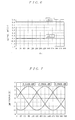
- the d-q axes voltage calculation memory table is composed of: electrical angles ⁇ e in the horizontal axis and d-axis voltage ed( ⁇ ) and q-axis voltage eq( ⁇ ) in the vertical axis, resulting from converting induced voltage waveforms that generate from the respective phase coils to rotational coordinates, as shown in FIG. 6 .
- both ed( ⁇ ) and q-axis voltage eq( ⁇ ) are constant values regardless of the electrical angle ⁇ .
- the q-axis electric current instruction value calculation section 33c calculates the q-axis electric current instruction value Iqref by computing the following Equation (3) based on the steering assist electric current instruction value Iref, the d-axis voltage ed( ⁇ e), the q-axis voltage eq( ⁇ e), the d-axis electric current instruction value Idref, and the electric angular velocity ⁇ e to be input.
- Iqref Kt ⁇ Iref ⁇ ⁇ e - ed ⁇ e ) ⁇ Idref ⁇ e / eq ⁇ e ) where Kt denotes a motor torque constant.
- the abnormal-time motor instruction value calculation section 34 calculates a phase current instruction value for continuing rotary drive of the three-phase brushless motor 12 using the remaining two phases.
- coils capable of being supplied with the motor current are only two coils that are V-phase coil Lv and W-phase coil Lw.
- Directions of the electric currents supplied to the V-phase coil Lv and the W-phase coil Lw include the following two cases: a case of when the motor current is input from the V-phase coil Lv and output from the W-phase coil Lw, and another case of when the motor current is input from the W-phase coil Lw and output from the V-phase coil Lv in an opposite manner.
- Stator synthetic magnetic fields generated by these motor currents can be formed only in completely opposite orientations as shown in FIGS. 8B and 8C . Accordingly, two-phase drive of the three-phase brushless motor 12 is impossible by using only these stator synthetic magnetic fields. Therefore, when a power distribution abnormality occurs in the drive system of the U phase, for example, a motor induced voltage when driving the motor using the remaining V phase and W phase is a composite induced voltage EMFa, which is indicated by a characteristic line L3, resulting from combining induced voltages EMFv ( ⁇ e) and ENFw ( ⁇ e) indicated by characteristic lines L1 and L2 for the electrical angles ⁇ e. Then, a phase current instruction value Im( ⁇ e) is calculated based on the composite induced voltage EMFa, and the aforementioned two-phase current instruction values are then calculated based on this phase current instruction value Im( ⁇ e).
- the abnormal-time motor instruction value calculation section 34 includes an acceleration region judgment section 61, a turn-from-center/return-to-center judgment section 62, an induced voltage calculation section 63, a phase current instruction value calculation section 64, a phase current instruction value correction section 65, an electric current limit section 66, and a two-phase current instruction value calculation section 67, as shown in FIG. 3 .
- the acceleration region judgment section 61 is supplied with the steering assist electric current instruction value Iref and the electrical angle ⁇ e. Firstly, an acceleration region is set based on the steering assist electric current instruction value Iref. The larger the steering assist electric current instruction value Iref becomes, the wider the acceleration region is set here. This acceleration region is set at a predetermined angular area that passes over an electrical angle ⁇ e reversing its sign of the phase current instruction value Im( ⁇ e) calculated by the phase current instruction value calculation section 64 described later.
- the acceleration region is set at the angular area including before and after an angular area in which the phase current instruction value Im( ⁇ ) reaches the phase current maximum value (the maximum electric current value Imax that can be output by the motor drive circuit 24) corresponding to the upper limit of the electric current value allowing power distribution in the drive system of each phase coil.
- the motor torque becomes always zero at the electrical angle ⁇ e that inverts the sign of the phase current instruction value Im( ⁇ e).
- the aforementioned acceleration region may also be called an angular area that includes the electrical angle ⁇ e making the motor torque zero.
- the acceleration region judgment section 61 judges whether or not the electric current electrical angle ⁇ e is within the above acceleration region. When it is within the acceleration region, an acceleration region judgment flag Fa is set to "1", and when it is outside of the acceleration region, the acceleration region judgment flag Fa is set to "0".
- the turn-from-center/return-to-center judgment section 62 is supplied with the steering torque T and the electrical angle velocity ⁇ e, and based thereon, judges whether steering manipulation of the steering wheel turns either in the turn-from-center direction or in the return-to-center direction.
- the steering torque sensor 3 is configured so as to give a sign to the steering torque T and output it with the generated torque during right steering being set to be a positive value and the generated torque during left steering being set to be a negative value.
- the differentiating circuit 32b of the three-phase brushless motor 12 is configured so as to give a sign in accordance with the rotation direction of the three-phase brushless motor 12 and output it.
- a positive value is given in the case of a rotation direction for applying a steering assist force at the time of steering to the right, and a negative value is given in the case of a rotation direction for applying a steering assist force at the time of steering to the left.
- the turn-from-center/return-to-center judgment section 62 judges that the turn-from-center steering is performed.
- the signs thereof differ, it judges that the return-to-center steering is performed.
- a turn-from-center/return-to-center judgment flag Fb is set to "1"
- the turn-from-center/return-to-center judgment flag Fb is reset to "0"
- the turn-from-center steering is judged, when the sign of the steering torque T is the same as that of steering torque rate of change and the absolute value of the steering torque rate of change is equal to or greater than a predetermined value.
- the return-to-center steering is judged, when the sign of the steering torque T is different from that of steering torque rate of change and the absolute value of the steering torque rate of change is equal to or greater than a predetermined value. In this case, judgment of turn-from-center/return-to-center steering is possible using only the steering torque T without using the electrical angle velocity ⁇ e.
- the induced voltage calculation section 63 calculates the composite induced voltage EMFa( ⁇ e) based on the electrical angle ⁇ e and an abnormality detection signal AS output from the abnormality detection circuit 27 to be described later.
- the induced voltage calculation section 63 has three memory tables for composite induced voltage calculation: a memory table for composite induced voltage calculation, which shows a relationship between composite induced voltage EMFa and electrical angle ⁇ e represented by the characteristic curved line L3 of FIG.
- a composite induced voltage calculation table which shows a relationship between composite induced voltage EMFa and electrical angle ⁇ e in the case of driving in the U-V2 phase
- a memory table for composite induced voltage calculation which shows a relationship between composite induced voltage EMFa and electrical angle ⁇ e in the case of driving in the U-W2 phase.
- the memory table for the composite induced voltage calculation corresponding to the two normal phases is selected based on the abnormality detection signal AS.
- the composite induced voltage EMFa( ⁇ e) is then calculated while referencing to the memory table for the composite induced voltage calculation selected based on the electrical angle ⁇ e.
- the phase current instruction value calculation section 64 calculates a phase current instruction value Im( ⁇ e) based on the composite induced voltage EMFa( ⁇ e) calculated by the induced voltage calculation section 63, the steering assist electric current instruction value Iref, and the electric angular velocity ⁇ e. That is to say, the phase instruction value calculation section 64 calculates the phase current instruction value Im( ⁇ e) by computing the following Equation (4).
- phase current instruction value correction section 65 is supplied with the phase current instruction value Im( ⁇ e) calculated by the phase current instruction value calculation section 64, corrects it, and the outputs a corrected phase current instruction value Im*( ⁇ e).
- the acceleration region judgment flag Fa is 1, increasing or decreasing of the phase current instruction value Im( ⁇ e) for correction is carried out in accordance with the turn-from-center/return-to-center judgment flag Fb and the steering assist electric current instruction value Iref.
- the phase current instruction value Im( ⁇ e) is increased for correction.
- Such an increase for correction in this case may be carried out by multiplying the phase current instruction value Im( ⁇ e) by a correction gain K1 (> 1), for example.
- the phase current instruction value Im( ⁇ e) is corrected by multiplying the phase current instruction value Im( ⁇ e) by a return-to-center correction gain K2 having the characteristics shown in FIG. 10 in accordance with the absolute value of the steering assist electric current instruction value Iref.
- the aforementioned thresholds Iref TH1 and Iref TH2 are set based on the steering assist electric current instruction value, as a reference, which generates external load enough for exerting a torque on the motor. Meanwhile, when the acceleration region judgment flag Fa is 0, the phase current instruction value Im( ⁇ e) is decreased for correction regardless of the turn-from-center/return-to-center judgment flag Fb and the steering assist electric current instruction value Iref.
- the decrease for correction in this case may be carried out by multiplying the phase current instruction value Im ⁇ e by a correction gain K3 ( ⁇ 1), for example.
- the electric current limit section 66 limits the phase current instruction value Im*( ⁇ e), which is calculated by the phase current instruction value correction section 65, with the predetermined maximum electric current value Imax.
- the predetermined maximum electric current value Imax in this case is set as an electric current upper limit that can be output by the motor drive circuit 24.
- the two-phase current instruction value calculation section 67 outputs two-phase current instruction values based on the phase current instruction value limited by the electric current limit section 66.
- two phases for power distribution are determined based on the abnormality detection signal AS output from the abnormality detection circuit 27, and in addition, the power distribution direction is set (whether or not electric current is passed from either of the aforementioned two phases for power distribution is set) based on the sign of the phase current instruction value Im*( ⁇ e).
- the instruction value selection section 35 includes: change-over switches 71u, 71v, and 71w; and a selection control section 72, which controls changing over these change-over switches 71u, 71v, and 71w.
- the phase current instruction values Iuref, Ivref, and Iwref calculated by the two-phase/three-phase conversion section 33e of the normal-time motor instruction value calculation section 33 are input to respective normally-closed contacts of the change-over switches 71u, 71v, and 71w, and the phase current instruction values Iuref, Ivref, and Iwref output from the abnormal-time motor instruction value calculation section 34 are input to the other respective normally-opened contacts.
- the selection control section 72 When the abnormality detection signal AS output from the abnormality detection circuit 27 is "0", which indicates that all of the phases are normal, the selection control section 72 outputs a select signal for the logical value "0" for selecting the normally-closed contacts of the change-over switches 71u, 71v, and 71w, and outputs a relay control signal for controlling interrupt relay circuits RLY1 to RLY3, described later, to turn on.
- the motor current control section 36 includes: subtracters 81u, 81v, and 81w; and a PI control section 82.
- the subtracters 81u, 81v, and 81w subtract the motor drive current detection values Iud, Ivd and Iwd flowing through the respective phase coils Lu, Lv, and Lw detected by the motor current detection circuit 22 from the respective phase current instruction values Iuref, lvref, and Iwref supplied from the instruction value selection section 35 so as to find respective phase current errors ⁇ Iu, ⁇ Iv, and ⁇ Iw.
- the PI control section 82 which performs proportional-plus-integral control for the found respective phase current errors ⁇ Iu, ⁇ Iv, and ⁇ Iw and calculates instruction voltages Vu, Vv, and Vw.
- the instruction voltages Vu, Vv, and Vw output from the PI control section 82 are then supplied to the FET gate drive circuit 25.
- the motor drive circuit 24 has an inverter structure in which switching elements Qua and Qub, Qva and Qvb, and Qwa and Qwb, which are composed of serially connected N-channel MOSFETs corresponding to the respective phase coils Lu, Lv, and Lw, are connected in parallel, as shown in FIG. 2 .
- a connection point of the switching elements Qua and Qub, a connection point of the switching elements Qva and Qvb, and a connection point of the switching elements Qwa and Qwb are each connected on the opposite side of a neutral point Pn of the phase coils Lu, Lv, and Lw.
- a Pulse Width Modulation (PWM) signal output from the FET gate drive circuit 25 is supplied to gates of the respective switching elements Qua and Qub, Qva and Qvb, and Qwa and Qwb that comprise the motor drive circuit 24.
- the interrupt relay circuit 26 is constituted by relay contacts RLY1, RLY2, and RLY 3, which are individually interposed between terminals on the opposite side of the neutral point Pn of the phase coils Lu, Lv, and Lw of the three-phase brushless motor 12 and the respective corresponding connection points of the field-effect transistors Qua and Qub, Qva and Qvb, and Qwa and Qwb of the motor drive circuit 24.
- the abnormality detection circuit 27 is capable of detecting non-conduction and short-circuit abnormalities in the U, V, and W phases by comparing the motor voltage of the respective phases to the voltage instruction values Vu, Vv, and Vw supplied to the FET gate drive circuit 25 or a pulse width modulation signal supplied to the motor drive circuit 24.
- the abnormality detection circuit 27 outputs to the abnormal-time motor instruction value calculation section 34 and the instruction value selection section 35 of the control calculation device 23, an abnormality detection signal AS including "0" when all of the U, V, and W phases are normal, "U1” when the U phase has a non-conduction abnormality, “U2” when the U phase has a short circuit abnormality, "V1” when the V phase has a non-conduction abnormality, “V2” when the V phase has a short circuit abnormality, "W1” when the W phase has a non-conduction abnormality, and “W2” when the W phase has a short circuit abnormality.
- the steering torque sensor 3 of FIG. 1 corresponds to a steering torque detection section
- the vehicle speed sensor 21 corresponds to a vehicle speed detection section
- the steering assist control device 20 corresponds to a motor control section
- the abnormality detection circuit 27 of FIG. 2 corresponds to a coil drive system abnormality detection section.
- the steering assist electric current instruction value calculation section of FIG. 1 corresponds to a steering torque detection section
- the vehicle speed sensor 21 corresponds to a vehicle speed detection section
- the steering assist control device 20 corresponds to a motor control section
- the abnormality detection circuit 27 of FIG. 2 corresponds to a coil drive system abnormality detection section.
- the normal-time motor instruction value calculation section 33 corresponds to a normal-time motor instruction value calculation section
- the induced voltage calculation section 63, the phase current instruction value calculation section 64, and the two-phase current instruction value calculation section 67 correspond to an abnormal-time motor instruction value calculation section
- the instruction value selection section 35 and the motor current control section 36 correspond to a motor drive control section.
- the acceleration region judgment section 61 correspond to an acceleration region judgment section
- the turn-from-center/return-to-center judgment section 62 corresponds to a steering direction judgment section
- the phase current instruction value correction section 65 corresponds to a motor rotation acceleration section
- the electric current limit section 66 corresponds to an electric current limit section.
- the respective field-effect transistors Qua to Qwb comprising the motor drive circuit 24 are assumed to be normal here, and the respective phase coils Lu to Lw of the three-phase brushless motor 12 are assumed in a normal state where neither disconnection nor earth fault has occurred.
- the abnormality detection circuit 27 outputs an abnormality detection signal AS representing "0" to the abnormal-time motor instruction value calculation section 34 and the instruction value selection section 35.
- the selection control section 72 of the instruction value selection section 35 outputs a selection signal for the logical value "0" to the change-over switches 71u to 71w. Therefore, the respective change-over switches 71u to 71w select the normally-closed contact and the phase current instruction values Iuref to Iwref output by the normal-time motor instruction value calculation section 33 are supplied to the motor current control section 36. At the same time, a relay control signal for controlling the respective relay contacts RLY1 to RLY3 into a closed state is output.
- the steering torque sensor 3 detects a large steering torque T in accordance therewith.
- the normal-time motor instruction value calculation section 33 calculates the phase current instruction values Iuref, Ivref and Iwref in accordance with this steering torque T and supplies them to the motor current control section 36.
- the motor current control section 36 then calculates instruction voltages Vu, Vv, and Vw based on the phase current instruction values Iuref, Ivref and Iwref and supplies them to the FET gate drive circuit 25.
- the respective field-effect transistors of the motor drive circuit 24 are controlled so as to rotary drive the three-phase brushless motor 12 as a result. Therefore, the three-phase brushless motor 12 generates a steering assist force in accordance with the steering torque T input to the steering wheel 1, and this force is conveyed to the steering shaft 2 via the acceleration gear 11. This allows the driver to steer the steering wheel 1 with a light steering force.
- this normal state changes to a state in which, for example, the drive system for driving the U-phase coil Lu, namely the field-effect transistors Qua and Qub of the motor drive circuit 24 keep in the off state, or to a state in which disconnection occurs at a power distribution path including the U-phase coil U due to a non-conduction abnormality developed in the U-phase coil Lu.
- the abnormality is detected by the abnormality detection circuit 27, and the abnormality detection circuit 27 then outputs an abnormality detection signal AS of "U1" representing non-conduction abnormality to the abnormal-time motor instruction value calculation section 34 and the instruction value selection section 35.
- phase current instruction values to be supplied to the motor current control section 36 may be changed over from phase current instruction values Iuref, Ivref and Iwref output by the normal-time motor instruction value calculation section 33 to phase current instruction values Iuref, Ivref and Iwref output by the abnormal motor instruction value calculation section 34. Since the abnormality detection signal AS input to the abnormal-time motor instruction value calculation section 34 from the abnormality detection circuit 27 is "U1", a composite induced voltage EMFa( ⁇ e) of the V-phase induced voltage and the W-phase induced voltage is calculated based on the electrical angle ⁇ e input from the angle information calculation section 32. The calculated composite induced voltage EMFa( ⁇ e) is supplied to the phase current instruction value calculation section 64, and the above Equation (4) is then computed by the phase current instruction value calculation section 64 so as to calculate the phase current instruction value Im( ⁇ e).
- the acceleration region judgment section 61 If the electrical angle ⁇ e does not reach the acceleration region at this time, the acceleration region judgment section 61 outputs an acceleration region judgment flag Fa which equals "0". Moreover, in the case when the driver is steering the steering wheel 1 in the turn-from-center direction at this time, the turn-from-center/return-to-center judgment section 62 outputs the turn-from-center/return-to center judgment flag Fb which equals "1". Therefore, the phase electric current instruction value calculation section 65 decreases for correction the phase current instruction value Im( ⁇ e) calculated by the phase current instruction value calculation section 64. The corrected phase current instruction value Im*( ⁇ e) is then supplied to the electric current limit section 66. When the phase current instruction value Im*( ⁇ e) exceeds the maximum electric current value Imax at this time, the electric current limit section 66 limits the phase current instruction value Im*( ⁇ e) to the maximum electric current value Imax.
- the phase current instruction value Im*( ⁇ e) output by the electric current limit section 66 is then supplied to the two-phase current instruction value calculation section 67.
- the two-phase current instruction value calculation section 67 sets whether to have electric current flow from either the V phase or the W phase based on the sign of the phase current instruction value Im*( ⁇ e), and then outputs the corresponding phase current instruction values Iuref, Ivref and Iwref to the selection switches 71u to 71w, respectively.
- the W-phase current instruction value Iwref is set to a positive value such that electric current flows from the W-phase coil Lw to the V-phase coil Lv.
- the W-phase current instruction value Ivref is set to a positive value such that electric current flows from the V-phase coil Lv to the W-phase coil Lw.
- the W-phase current instruction value Iwref is set to a positive value such that electric current flows from the W-phase coil Lw to the V-phase coil Lv.
- the U-phase current instruction value Iuref is set to "0".
- the V-phase current instruction value and the W-phase current instruction value are set to have mutually opposite signs such that the absolute values thereof are equal (set so that sum of the electric current instruction values of two normal phases is zero).
- FIG. 11 is a diagram illustrative of motor current and motor torque during the turn-from-center steering.
- the broken lines indicate motor current and motor torque in the case where the phase current instruction value Im( ⁇ e) is not corrected, and solid lines indicate motor current and motor torque in the where the phase current instruction value Im( ⁇ e) is corrected.
- circles and arrows in the drawing indicate states of the motor.
- both the motor torque direction and the motor rotation direction are positive (direction from left to right in FIG. 11 ), and the direction of an external load exerted on the motor is negative (direction from right to left in FIG. 11 ).
- the motor current increases to a maximum negative electric current value in a circular arc convex at the top in a region (region before reaching region A) before the motor current reaches the electric current upper limit.
- region A the maximum negative value is maintained in the region before 90 degrees, and the maximum positive value is maintained in the region after the sign is inverted at 90 degrees.
- the motor current decreases from the maximum positive value in a circular arc convex at the bottom.
- the motor torque becomes a steady value at this time in the angular areas before and after the region A, as shown by the broken lines in FIG. 11 .
- the motor torque then decreases and becomes zero at 90 degrees in region A where the phase current reaches the electric current upper limit.
- the angular areas before and after the region A are stable output angular areas capable of outputting a steady motor torque.
- the region A is an unstable output angular area in which electric current is limited by maximum electric current value Imax that can be output from the motor drive circuit 24, and is incapable of providing a stable motor torque.
- the electric current limit section 66 supplies to the two-phase current instruction value calculation section 67 the phase current instruction value Im*( ⁇ e) without changing the value supplied from the phase current instruction value correction section 65.
- the motor current is decreased for correction in the stable output angular area before reaching the acceleration region D, thereby decreasing the motor torque in this region.
- the acceleration region judgment section 61 outputs an acceleration region judgment flag Fa which equals "1".
- the phase current instruction value calculation section 65 increases for correction the phase current instruction value Im( ⁇ e) calculated by the phase current instruction value calculation section 64.
- the motor current is increased for correction, when the acceleration region D is reached.
- This increases the motor torque and accelerates the three-phase brushless motor 12.
- the electrical angle ⁇ e falls within the acceleration region D.
- the phase current instruction value Im*( ⁇ e) exceeds the maximum electric current value Imax due to the increase for correction by the phase current instruction value calculation section 65
- the electric current is limited by the electric current limit section 66. Accordingly, in the acceleration region D, the maximum negative value and the maximum positive value are maintained in the respective regions before and after 90 degrees. Namely, in regions B and C before and after the region A, the motor current is greater than the case where no correction is indicated by broken lines, so the motor torque thus increases as well.
- the motor current is increased or decreased for correction in the stable output angular areas before and after reaching the electric current limit, namely angular areas freely allowing increase or decrease in the motor torque.
- the acceleration region judgment section 61 outputs an acceleration region judgment flag Fa which equals "0". Therefore, the phase current instruction value calculation section 65 decreases again, for correction, the phase current instruction value Im( ⁇ e) calculated by the phase current instruction value calculation section 64to decrease the motor torque.
- acceleration region D since the motor is accelerated in the positive direction even in the region C after passing over the region A, the motor may be prevented from falling within region A again due to the external load exerted on the motor in the negative direction after region A is passed over once. This allows the motor to progress in the positive direction appropriately, as shown in the state from circle c to circle d in the drawing. As such, when an abnormality occurs in one of the three phases, continued driving of the three-phase brushless motor 12 using the remaining two phases is possible. Furthermore, at this time, the region A incapable of providing a stable motor torque due to the electric current limitation can be effectively passed over.
- the turn-from-center/return-to-center judgment section 62 outputs the turn-from-center/return-to-center flag Fb which equals 0. If the steering assist electric current instruction value Iref is equal to or greater than a threshold Iref TH at this time, the phase current instruction value correction section 65 corrects the motor current to set to "0" in the acceleration region, and at the same time corrects for decreasing the motor current outside of the acceleration region.
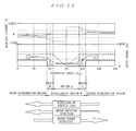
- FIG. 12 is a diagram illustrative of motor current and motor torque during the return-to-center steering (high-level current).
- the motor torque direction and the motor rotation direction are not the same. That is, while the motor torque direction is positive (direction from left to right in FIG. 12 ), the motor rotation direction is negative as is the direction of an external load exerted on the motor (direction from right to left in FIG. 12 ).
- the phase current instruction value correction section 65 decreases, for correction, the phase current instruction value Im( ⁇ e). This decreases the motor torque in the region before the acceleration region D. If the electrical angle ⁇ e reaches the acceleration region D, the phase current instruction value correction section 65 corrects the phase current instruction value Im( ⁇ e) to set to "0". This decrease for correction continues while the electrical angle ⁇ e falls within the acceleration region D. Thus, the motor torque also becomes "0" in the acceleration region D.
- the difference in the motor torque is small before and after reaching the acceleration region D. This allows facilitation of transfer of the state of the motor from circle a to circle b. If the electrical angle ⁇ e passes the acceleration region D thereafter, the phase current instruction value correction section 65 decreases again, for correction, the phase current instruction value Im( ⁇ e). The motor torque is decreased as a result. Therefore, even in this case, in the acceleration region D and after the acceleration region D is passed, the difference in the motor torque can be reduced and transfer of the state of the motor from circle c to circle d can be facilitated.
- the phase current instruction value correction section 65 corrects the motor current by inverting and decreasing the motor current in the acceleration region, and in addition, decreases for correction the motor current outside of the acceleration region.
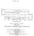
- FIG. 13 is a diagram illustrative of the phase electric current and motor torque during the return-to-center steering (low-level current). Namely, in the region before the electrical angle ⁇ e reaches the acceleration region D, the phase current instruction value correction section 65 decreases for correction the phase current instruction value Im( ⁇ e). This decreases the motor torque in the region before the acceleration region D. If the electrical angle ⁇ e reaches the acceleration region D, the phase current instruction value correction section 65 inverts the sign of the phase current instruction value Im( ⁇ e) and decreases for correction the value.
- phase current instruction value Im( ⁇ e) changes dramatically, there is a possibility of exceeding a control response property of electric current feedback control and becoming overcurrent.
- the signal of the phase current instruction value Im( ⁇ e) is inverted, the value is decreased for correction. This prevents a dramatic change in the phase current at the time of transferring from the outside of the acceleration region D into the acceleration region D (or the reverse), thereby preventing overcurrent.
- phase current instruction value correction section 65 decreases, for correction, the phase current instruction value Im( ⁇ e) again.
- the motor torque is decreased as a result. Therefore, even in this case, in the acceleration region D and after the acceleration region D is passed, the difference in the motor torque can be reduced, and transfer of the state of the motor from circle c to circle d can be facilitated.
- FIG. 14 is a diagram describing operations in the aforementioned comparative example.
- FIG. 14A shows the phase current at the time of turn-from-center steering
- FIG. 14B shows the motor torque at the time of the turn-from-center steering
- FIG. 14C shows the phase current at the time of the return-to-center steering
- FIG. 14D shows the motor torque at the time of the return-to-center steering. They all illustrate a case of disconnecting the U phase and carrying out rotation drive of a motor in the V phase and the W phase.
- the rotation of the motor accelerates in the positive direction since the motor torque is increased due to the over-assist characteristic immediately before the motor rotation angles (90 and 270 degrees) at which the motor torque becomes 0, as shown in FIG. 14A and FIG. 14B .
- the motor torque is decreased due to the under-assist characteristic immediately after the motor rotation angle (90 degrees in this case) at which the motor torque becomes 0. Therefore, the motor rotation angle may stop at 90 degrees as a result of the motor decelerating due to an external load, and the motor rotation angle may give in to the external load and return to 90 degrees.
- the rotation of the motor accelerates in the negative direction since the motor torque is decreased due to the under-assist characteristic immediately before the motor rotation angles (90°, 270°) at which the motor torque becomes 0, as shown in FIG. 14C and FIG. 14D .
- the motor torque is increased due to the over-assist characteristic immediately after the motor rotation angle (270° in this case) at which the motor torque becomes 0. Therefore, this may become a braking torque (become a barrier of torque), stopping the motor rotation angle at 270 degrees.
- the reverse assist characteristic acts as a braking torque, making it easy for the motor to return to the region A.
- the over-assist characteristic acts as a braking torque, making it easy for the motor to stop at the region A. In this manner, since the methods of passing over the region A in these comparative examples are inefficient, it is difficult to employ in a brushless motor with fewer poles and with a larger region A.
- the phase current instruction value Im( ⁇ e) is corrected so as for the motor to be intentionally accelerated in the steering direction in the acceleration region including before and after the region incapable of providing a stable motor torque due to electric current limitations.
- the correction method of the phase current instruction value Im( ⁇ e) is changed in accordance with the steering operations (turn-from-center/return-to-center) of the steering wheel 1. Therefore, with a configuration suited even for a state where appropriate motor torque direction and motor rotation direction for electric power steering do not match, it is possible to pass over the region incapable of providing a stable motor torque.
- the abnormality detection circuit 27 outputs an abnormality detection signal AS represented by "U2", when the abnormality of the U-phase drive system detected by the abnormality detection circuit 27 is a short-circuit abnormality at the field-effect transistors Qua and Qub of the motor drive circuit 24.
- this selection control section 72 supplies to the interrupt relay circuit RLY1 for the U phase a relay control signal, which causes the interrupt relay circuit RLY1 to enter an interrupted state.
- a power supply system for the U-phase coil Lu of the three-phase brushless motor 12 is accordingly interrupted. Except for this operation, the same processes for the aforementioned non-conduction abnormality are performed so as to control the two-phase power distribution of the three-phase brushless motor 12. Consequently, rotary drive of the motor can be continued even in this case.
- the normal-time motor instruction value calculation section 33 calculates the respective phase current instruction values Iuref to Iwref as usual, and controls feedback of the three-brushless motor 12 based thereon. This allows the three-phase brushless motor 12 to generate a steering assist force in accordance with the steering torque T and the vehicle speed Vs, thereby allowing optimal steering assist control.
- the abnormal-time motor instruction value calculation section 34 calculates the phase current instruction values Iuref to Iwref in the case of using coils in the two normal phases, and controls feedback of the three-brushless motor 12 based thereon. Consequently, this allows contonous driving of the three-phase brushless motor 12.
- the abnormal-time phase current instruction value is corrected in an angular area including an electrical angle ⁇ e in which the sign of the abnormal-time phase current instruction value is inverted and the motor torque then becomes zero, namely, an acceleration region before and after angular area (unstable output angular area) incapable of providing a stable motor torque, so that rotation of the three-phase brushless motor 12 is intentionally accelerated in the steering direction.
- This allows acceleration of the motor before reaching the unstable output angular area.
- the abnormal-time phase current instruction value is increased or decreased for correction after the unstable output angular area is passed, it is possible to prevent the torque from becoming insufficient after the unstable output angular area is passed once, and then from falling again into the unstable output angular area.
- the abnormal-time phase current instruction value is increased or decreased for correction such that the motor accelerates in the steering direction, it is possible to prevent the generation of a braking torque in the above acceleration region.
- the unstable output angular area may be efficiently passed over by a motor inertia force, so the steering feeling may be improved. It is also applicable even to a brushless motor with a large unstable output angular area (brushless motor with a smaller shaft angle multiplication).
- the larger the steering assist electric current instruction value Iref the larger the acceleration region is set in consideration of the fact that the larger the steering assist electric current instruction value Iref, the larger the angular area width (unstable output angular area width) that reaches the electric current upper limit.
- the region including before and after the angular area reaching the electric current upper limit may be reliably set as the acceleration region, as in this manner.
- the abnormal-time phase current instruction value can be increased or decreased for correction in the angular area allowing free increase and decrease of the motor torque before and after the unstable output angular area.
- motor torque characteristics for passing over the unstable output angular area can be obtained with certainty.
- the abnormal-time phase current instruction value is increased as overtorque so as to accelerate the motor in the rotation direction.
- the abnormal-time phase current instruction value is set to zero with utilizing the fact that the direction of the external load exerted on the motor and the motor rotation direction are the same. As a result, the motor is accelerated in the rotation direction by the external load exerted on the motor.
- the correction amount of the abnormal-time phase current instruction value is gradually changed. Therefore, smooth steering may be maintained, thus preventing any discomfort.
- the abnormal-time phase current instruction value is decreased for correction at the outside of the acceleration region. Therefore, in the turn-from-center steering, the steering torque is intentionally increased in the angular area before the electrical angle reaches the acceleration region, the external load exerted on the motor is kept small, thereby facilitating motor acceleration. Furthermore, in the return-to-center steering, the motor torque is decreased in the angular area before the electrical angle reaches the acceleration region. This allows control of differences in the motor torque when a stable output angular area is transferred to the acceleration region (or vice versa), thereby facilitating transfer to the stable region.
- This second embodiment has been made so as to change the magnitude of the maximum electric current value Imax in accordance with the vehicle speed Vs in contrast to the first embodiment described above having the maximum electric current value Imax fixed by an electric current limiting value.
- FIG. 15 is a block diagram illustrative of the configuration of a control calculation device 23 according to the second embodiment.
- the control calculation device 23 in this second embodiment has the same configuration as that of the control calculation device 23 shown in FIG. 3 except that the vehicle speed Vs detected by the vehicle speed sensor 21 is input to the electric current limit section 66. Accordingly, such different configuration will be mainly described here.
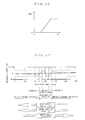
- the electric current limit section 66 limits the phase current instruction value Im*( ⁇ e) calculated by the phase current instruction value correction section 65. At this time, the lower the vehicle speed Vs, the smaller the maximum electric current value, so that the maximum electric current value Imax is set to 0 (or substantially 0) at a low vehicle speed including vehicle stopped state. In other words, the maximum electric current value Imax is set as shown in FIG. 16 , for example.
- characteristics of the maximum electric current value Imax are not limited to those shown in FIG. 16 as long as the maximum electric current value Imax is set to 0 (or substantially0) during the aforementioned low vehicle speed.
- the maximum electric current value Imax is set to 0 by the electric current limit section 66 of the abnormal-time motor instruction value calculation section 34.
- the electric current limit section 66 therefore limits the phase current instruction value Im*( ⁇ e) to "0" and supplies it to the two-phase current instruction value calculation section 67.
- the respective phase current instruction values Iuref to Iwref are each set to "0", and the steering assist becomes "0", thereby changing to a manual steering state.
- the external load exerted on the motor when the vehicle is running is extremely large.
- the acceleration energy for passing over the angular area incapable of providing a stable motor torque becomes extremely large as a result.
- the angular area incapable of providing a stable motor torque cannot be passed over. Therefore, a strong feeling of being caught on something may be presented to the driver. Although this is not reflected in the vehicle behavior at this time, there is a possibility that a situation such as the driver's fingers being caught on the steering wheel due to a sudden change in the load of the steering wheel.
- the maximum electric current value Imax used for electric current limitation is set smaller by the electric current limit section 66.
- the maximum electric current value Imax is set to "0" and the steering assist is also set to "0".
- the maximum abnormal-time phase current instruction value is limited by a predetermined maximum electric current value (electric current limiting value) in the above second embodiment.
- a predetermined maximum electric current value electric current limiting value
- the maximum electric current value is set to zero and the steering assist is also set to zero.
- FIG. 17 is a diagram illustrative of the motor current when the rate thereof is limited. Motor current at the time of the return-to-center steering (low-level current) is given here. Limiting the rate of the corrected phase current instruction value Im*( ⁇ e) in this manner allows a more gradual change in the motor current, when the motor current is transferred from the outside of the acceleration region D into the acceleration region D (or vice versa) or when the sign of the phase current instruction value Im*( ⁇ e) is inverted. As a result, generation of overcurrent due to a sudden change in the motor current may be controlled.
- the phase current instruction value Im*( ⁇ e) may be limited by the maximum electric current value Imax in accordance with the vehicle speed Vs only at the time of the turn-from-center steering, and the maximum electric current value Imax may be fixed by an electric current limit at the time of the return-to-center steering. This allows acceleration of the motor in the steering direction using a large external load on the motor, as in the first embodiment described above, at the time of the return-to-center steering, thereby achieving appropriate steering assist control.
- phase current instruction value Im( ⁇ e) at a fixed rate by multiplying a preset correction gain when the electrical angle falls within the acceleration region.
- increasing or decreasing for correction may be carried out by adding a fixed correction amount to the phase current instruction value Im( ⁇ e) or subtracting a fixed correction amount therefrom, respectively.
- increasing or decreasing for correction may be carried out such that the corrected phase current instruction value Im*( ⁇ e) becomes a preset, predetermined value.
- the correction amount of the phase current instruction value Im( ⁇ e) may also be changed in accordance with the magnitude of the steering assist electric current instruction value Iref.
- any one of the interruption relay circuits RLY1 to RLY 3 may be omitted.
- a short-circuit occurs at the electric-field transistor of the upper arm or lower arm of the motor drive circuit in the drive system that includes the omitted interruption relay circuit, such a short-circuited transistor does not work any longer and applicable regions for two-phase drive in the three-phase brushless motor during normal operation are reduced to only two regions, which will not pose a serious problem.
- this two-phase/three-phase conversion section may be omitted.
- the entire control calculation device 23 may be composed of a vector control system, which supplies the motor drive current detection values Iud, Ivd and Iwd output from the motor current detection circuit 22 to a three-phase/two-phase conversion section, converts them to d-axis electric current Idd and q-axis electric current Iqd in rotational coordinates, calculates electric current deviations ⁇ Id and ⁇ Iq by subtracting the d-axis electric current Idd and the q-axis electric current Iqd from a d-axis electric current instruction value Idref and a q-axis electric current instruction value Iqref by the motor current control section 36, calculates d-axis instruction voltage Vd and q-axis instruction voltage Vq through PI control thereof at the PI control section 82, converts them into three-phase instruction voltages Vu, vv, and Vw by the three-phase/two-phase conversion section, and supplies the
- the electric power steering device of the present invention when an abnormality occurs in one phase of a three-phase brushless motor, continuous driving of the motor using the remaining two phases is possible, which is useful. Moreover, since the unstable output angular area in which motor torque decreases may be efficiently passed over by a motor inertia force, the steering feeling may be improved, which is useful.
Landscapes
- Engineering & Computer Science (AREA)
- Chemical & Material Sciences (AREA)
- Combustion & Propulsion (AREA)
- Transportation (AREA)
- Mechanical Engineering (AREA)
- Power Engineering (AREA)
- Control Of Motors That Do Not Use Commutators (AREA)
- Power Steering Mechanism (AREA)
- Steering Control In Accordance With Driving Conditions (AREA)
Abstract
Description
- The present invention relates to an electric power steering device, which provides to a steering system a steering assist force for driving and controlling a three-phase brushless motor to reduce a driver's steering load.
- The technology disclosed in
Patent Document 1 is an example of a conventional electric power steering device. With this technology, when an abnormality occurs in one phase of a three-phase brushless motor, an abnormality electric current instruction value for keeping motor torques almost constant is calculated based on back electromotive voltage information of the remaining two phases so that the motor is continuously driven based on the above abnormality electric current instruction value.
However, the amount of electric current passed through the motor is limited by restrictions such as hardware and the like. Therefore, a constant motor torque cannot be obtained in the angular area in which the electric current limit is reached, so the driver feels as if the steering wheel were caught by something, thereby deteriorating the steering feeling. - There is a technology of providing an over-assist characteristic in a smaller angular area than the angular area in which a constant torque is not obtained so as to increase the motor torque, and providing an under-assist characteristic in a larger angler area than the angular area in which the constant torque is not obtained so as to decrease the motor torque (See
Patent Document 2, for example). This technology aims at accelerating the rotation of the motor before reaching the angular area in which the constant torque is not obtained so as to pass over this angular area. -
- Patent Document 1:
JP 2009-6963 A - Patent Document 2:
WO 2005/091488 - The electric power steering device disclosed in the
above Patent Document 2 performs turn-from-center steering, and in the case where both the motor torque direction and the motor rotation direction are positive directions, rotation of the motor may be accelerated in the positive direction by increasing the motor torque just before reaching the angular area in which a constant torque is not obtained. However, since the motor torque is reduced immediately after passing over the angular area, rotation of the motor easily decreases due to the external load, and easily stops in the angular area in which the constant torque is not obtained. - Moreover, in the case where the return-to-center steering is performed, the motor torque direction is a positive one, and the motor rotation direction is a negative one, rotation of the motor may be accelerated in the negative direction by decreasing the motor torque just before reaching the angular area in which the constant torque is not obtained. However, since the motor torque is increased immediately after passing over the angular area, this becomes a braking torque whereby the motor may stop in the angular area in which the constant torque cannot be obtained.
- As a result, an insufficient assist is provided while shifting from return-to-center steering to turn-from-center steering, and thereby presenting to the driver a feeling as if the steering wheel were caught on something.
Therefore, it is an object of the present invention to provide an electric power steering device which, when an abnormality has occurred in one phase of a three-phase brushless motor, permits continuous driving of the motor using the remaining two phases without deteriorating the steering feeling. - In order to achieve the above object, a first aspect of an electrical power steering device according to the present invention is characterized by including a three-phase brushless motor having respective phase coils connected in a star connection for applying a steering assist force to a steering system; a steering torque detection section for detecting a steering torque transmitted to the steering system; and a motor control section for controlling the three-phase brushless motor to drive based on at least the steering torque detected by the steering torque detection section. The motor control section includes a coil drive system abnormality detection section for detecting a power distribution abnormality in a drive system of the respective coils; a steering assist electric current instruction value calculation section for calculating a steering assist electric current instruction value based on the steering torque detected by the steering torque detection section; a normal-time motor instruction value calculation section for, when an abnormality of the drive system of the respective phase coils has not been detected by the coil drive system abnormality detection section, calculating a normal-time phase current instruction value using three phase coils based on the steering assist electric current instruction value; an abnormal-time motor instruction value calculation section for, when an abnormality of the drive system of one phase of the respective phase coils has been detected by the coil drive system abnormality detection section, calculating an abnormal-time phase current instruction value based on the steering assist electric current instruction value such that sum of phase current instruction values of the remaining two phases is zero; a motor drive control section for selecting any one of the normal-time phase current instruction value calculated by the normal-time motor instruction value calculation section and the abnormal-time phase current instruction value calculated by the abnormal-time motor instruction value calculation section, and for controlling the three-phase brushless motor to drive based on the selected phase current instruction value; an acceleration region judgment section for judging whether or not an electrical angle of the three-phase brushless motor falls within an acceleration region, which is a predetermined angular area including the electrical angle at which the sign of the abnormal-time phase current instruction value calculated by the abnormal-time motor instruction value calculation section is inverted; and a motor rotation acceleration section for, when the electrical angle of the three-phase brushless motor is judged to fall within the acceleration region, correcting the abnormal-time phase current instruction value calculated by the abnormal-time motor instruction value calculation section so as to accelerate rotation of the three-phase brushless motor in a steering direction.
- Moreover, a second aspect of the present invention is characterized in that the acceleration region is set to be wider as the steering assist electric current instruction value calculated by the steering assist electric current instruction value calculation section is larger.
Furthermore, a third aspect of the present invention is characterized in that the acceleration region is an angular area including before and after an angular area in which the abnormal-time phase current instruction value calculated by the abnormal-time motor instruction value calculation section reaches a phase current upper limit value corresponding to an upper limit of electric current values by which the drive system of the respective phase coils is energized. - Yet even further, a fourth aspect of the present invention is characterized by further including a steering direction judgment section for judging whether a steering manipulation causes a steering wheel is in a turn-from-center direction or a return-to-center direction. The motor rotation acceleration section changes a correction method of the abnormal-time phase current instruction value in accordance with the steering direction judged by the steering direction judgment section.
Yet even further, a fifth aspect of the present invention is characterized in that the motor rotation acceleration section increases for correction the abnormal-time phase current instruction value when the steering direction judged by the steering direction judgment section is the turn-from-center direction. - Yet even further, a sixth aspect of the present invention is characterized in that the motor rotation acceleration section corrects the abnormal-time phase current instruction value to be zero or substantially zero when the steering direction judged by the steering direction judgment section is the return-to-center direction and the steering assist electric current instruction value calculated by the steering assist electric current instruction value calculation section is equal to or greater than a predetermined value.
Yet even further, a seventh aspect of the present invention is characterized in that the motor rotation acceleration section inverts for correction the sign of the abnormal-time phase current instruction value when the steering direction judged by the steering direction judgment section is the return-to-center direction and the steering assist electric current instruction value calculated by the steering assist electric current instruction value calculation section is smaller than the predetermined value. - Yet even further, an eighth aspect of the present invention is characterized in that the motor rotation acceleration section inverts for correction the sign of the abnormal-time phase current instruction value and decrease the abnormal-time phase current instruction value when the steering direction judged by the steering direction judgment section is the return-to-center direction and the steering assist electric current instruction value calculated by the steering assist electric current instruction value calculation section is smaller than the predetermined value.
Yet even further, a ninth aspect of the present invention is characterized in that the motor rotation acceleration section is provided with a gradual-change region in which a correction amount of the abnormal-time phase current instruction value is gradually changed according to the steering assist electric current instruction value during change-over of the correction method of the abnormal-time phase current instruction value based on the predetermined value when the steering direction judged by the steering direction judgment section is the return-to-center direction. - Yet even further, a tenth aspect of the present invention is characterized in that the motor rotation acceleration section limits an upper limit of a rate of change in the abnormal-time phase current instruction value after corrected by a predetermined rate of change limiting value.
Yet even further, an eleventh aspect of the present invention is characterized by further including a vehicle speed detection section for detecting a vehicle speed. The motor control section includes an electric current limit section for limiting a maximum value of the abnormal-time phase current instruction value by an electric current limiting value in accordance with the vehicle speed detected by the vehicle speed detection section. The electric current limit section sets the electric current limiting value to zero or substantially zero when the vehicle speed detected by the vehicle speed detection section is smaller than a predetermined value.
Yet even further, a twelfth aspect of the present invention is characterized in that the motor control section includes a decreasing correction section for decreasing for correction the abnormal-time phase current instruction value calculated by the abnormal-time phase current instruction value calculation section when the electrical angle is judged by the acceleration region judgment section as being outside of the acceleration region. - According to the present invention, when an abnormality occurs in one phase of a three-phase brushless motor, continuous driving of the motor using the remaining two phases is possible. Moreover, since intentional acceleration of rotation of the motor is carried out in the steering direction in the acceleration region including an electrical angle in which the sign of the abnormality phase current instruction value calculated by the abnormal-time phase current instruction value calculation section is inverted, generation of a braking torque in the acceleration region may be prevented. As a result, an unstable output angular area in which motor torque decreases may be efficiently passed over by a motor inertia force and the steering feeling may be improved.
-
-
FIG. 1 is a system schematic diagram of an electric power steering device of the present invention; -
FIG. 2 is a block diagram illustrative of a configuration of a steering assist control device; -
FIG. 3 is a block diagram illustrative of a configuration of acontrol calculation device 23 according to a first embodiment; -
FIG. 4 is a steering assist electric current instruction value calculating map; -
FIG. 5 is a block diagram illustrative of a configuration of a d-axis electric current instruction value calculation section of a vector phase instruction value calculation circuit; -
FIG. 6 is a characteristic line graph for a d-q axes voltage calculation memory table; -
FIG. 7 is a characteristic line graph illustrating induced voltage waveforms generated by a three-phase brushless motor during normal operation; -
FIG. 8 is an illustration of a configuration of a stator magnetic field model during two-phase power distribution in the three-phase brushless motor; -
FIG. 9 is a characteristic line graph showing motor induced voltages during two-phase power distribution in the three-phase brushless motor; -
FIG. 10 is a diagram illustrative of an example of return-to-center correction gains; -
FIG. 11 is a diagram illustrative of motor current and motor torque during turn-from-center steering; -
FIG. 12 is a diagram illustrative of motor current and motor torque during return-to-center steering (high level current); -
FIG. 13 is a diagram illustrative of motor current and motor torque during return-to-center steering (low level current); -
FIG. 14 is a diagram describing operations in a comparative example; -
FIG. 15 is a block diagram illustrative of a configuration of acontrol calculation device 23 according to a second embodiment; -
FIG. 16 is a diagram illustrative of an example of the maximum electric current values Imax; and -
FIG. 17 is a diagram describing modifications of the present invention. - Embodiments of the present invention will now be described with reference to the drawings.
-
FIG. 1 is an overall schematic view illustrative of a first embodiment of the present invention.
In the drawing,reference numeral 1 denotes a steering wheel, where a steering force applied from a driver to thesteering wheel 1 is transmitted to asteering shaft 2. Thissteering shaft 2 has aninput shaft 2a and anoutput shaft 2b. An end of theinput shaft 2a is connected to thesteering wheel 1, and the other end is connected to an end of theoutput shaft 2b via asteering torque sensor 3. - The steering force transmitted to the
output shaft 2b is transmitted to alower shaft 5 via auniversal joint 4 and then transmitted to apinion shaft 7 via auniversal joint 6. The steering force transmitted to thepinion shaft 7 is transmitted to a tie rod 9 via asteering gear 8, thereby turning wheels not illustrated in the drawing. In this case, thesteering gear 8 is a rack-and-pinion type gear having apinion 8a connected to thepinion shaft 7 and arack 8b meshing with thepinion 8a, and the rotary motion transmitted to thepinion 8a is converted by therack 8b into translatory movement in the vehicle width direction. - A
steering assist mechanism 10, which transmits a steering assist force to theoutput shaft 2b of thesteering shaft 2, is connected to theoutput shaft 2b. Thesteering assist mechanism 10 includes adecelerating gear 11 connected to theoutput shaft 2b, and a three-phase brushless motor 12, which is connected to thedecelerating gear 11, generates a steering assist force.
Thesteering torque sensor 3 is detects a steering torque applied from thesteering wheel 1 and then transmitted to theinput shaft 2a. For example, thesteering torque sensor 3 is configured to convert the steering torque to twist angular displacement of a torsion bar, not illustrated, for inserting the steering torque between theinput shaft 2a and theoutput shaft 2b, and then convert the twist angular displacement to resistance variation or magnetic variation to be detected. - Moreover, as shown in
FIG. 2 , the three-phase brushless motor 12 is made into a star connection by connecting one ends of a U-phase coil Lu, a V-phase coil Lv, and a W-phase coil Lw to each other, and the other ends of the respective coils Lu, Lv, and Lw are connected to a steeringassist control device 20 to be supplied with motor drive currents Iu, Iv, and Iw, respectively. Furthermore, the three-phase brushless motor 12 includes a rotor rotationangle detection circuit 13, which is configured of a Hall device, a resolver, and the like, for detecting the rotational position of a rotor. - A steering torque T detected by the
steering torque sensor 3, a vehicle speed Vs detected by avehicle speed sensor 21, and a rotor rotation angle θm detected by the rotor rotatingangle detection circuit 13 are input to the steering assistcontrol device 20. Moreover, motor drive current detection values Iud, Ivd and Iwd are output from a motorcurrent detection circuit 22, which detects the motor drive currents Iu, Iv, and Iw to be supplied to the respective phase coils Lu, Lv, and Lw of the three-phase brushless motor 12, and are then input to the steering assistcontrol device 20. - The steering
assist control device 20 includes: acontrol calculation device 23, which calculates a steering assist electric current instruction value based on the steering torque T, the vehicle speed Vs, the motor drive current detection values Iud, Ivd and Iwd, and the rotor rotation angle θm, and then outputs respective phase voltage instruction values Vu, Vv, and Vw; amotor drive circuit 24, which is configured of field-effect transistors (FETs) that drive the three-phase brushless motor 12; and a FETgate drive circuit 25, which controls the gate current of the field-effect transistor of themotor drive circuit 24 based on the phase voltage instruction values Vu, Vv, and Vw output from thecontrol calculation device 23. The steeringassist control device 20 further includes: an interruptrelay circuit 26, which is connected between themotor drive circuit 24 and the three-phase brushless motor 12; and anabnormality detection circuit 27, which detects abnormalities of the motor drive currents Iu, Iv, and Iw that are supplied to the three-phase brushless motor 12. -
FIG. 3 is a block diagram illustrative of the configuration of thecontrol calculation device 23.
Thecontrol calculation device 23 includes: an instructionvalue output section 30, which is configured of a steering assist electric current instructionvalue calculation section 31; an angleinformation calculation section 32; a normal-time motor instructionvalue calculation section 33; an abnormal-time motor instructionvalue calculation section 34; an instructionvalue selection section 35; and a motorcurrent control section 36, as shown inFIG. 3 .
The steering assist electric current instructionvalue calculation section 31 is supplied with the steering torque T detected by thesteering torque sensor 3 and the vehicle speed Vs detected by thevehicle speed sensor 21, and then calculates a steering assist electric current instruction value Iref based thereon. - The angle
information calculation section 32 calculates an electrical angle θe and an electric angular velocity we based on the rotor rotation angle θm detected by the rotor rotatingangle detection circuit 13.
The normal-time motor instructionvalue calculation section 33 calculates three-phase current instruction values (normal-time phase current instruction values) Iuref to Iwref based on the steering assist electric current instruction value Iref, the electrical angle θe, and the electric angular velocity we. - The abnormal-time motor instruction
value calculation section 34 calculates two-phase current instruction values (abnormal-time phase current instruction values) Iiref and Ijref for normal coils Li (i equals u to w) and Lj (j equals v to u) based on an abnormality detection signal AS, the steering assist electric current instruction value Iref, the electrical angle θe, and the electric angular velocity ωe input from anabnormality detection circuit 27 to be described later. At this time, Iiref and Ijref are.calculated with mutually opposite signs and equal absolute values. Namely, the sum of Iiref and Ijref is zero, and signs thereof are inverted at the common electrical angle θe. - The instruction
value selection section 35 selects either the three-phase current instruction values Iuref to Iwref output from the normal-time motor instructionvalue calculation section 33 or the two-phase current instruction values Iiref and Ijref output from the abnormal-time motor instructionvalue calculation section 34.
The motorcurrent control section 36 performs a current feedback process using the electric current instruction values selected by the instructionvalue selection section 35 and the motor current detection values Iud, Ivd and Iwd detected by the motorcurrent detection circuit 22. - Processing executed in each block is described in detail below.
The steering assist electric current instructionvalue calculation section 31 calculates the steering assist electric current instruction value Iref based on steering torque T and vehicle speed Vs with reference to a steering assist electric current instruction value calculating map given inFIG. 4 . The steering assist electric current instruction value calculating map is composed of a characteristic line graph represented by parabolic curved lines with the detected vehicle speed Vs as a parameter, where the horizontal axis gives steering torque T and the vertical axis gives steering assist electric current instruction values Iref, as shown inFIG. 4 . The characteristic line graph is set such that the steering assist electric current instruction value Iref remains at "0" from where the steering torque T is "0" until a preset value Ts1 in the vicinity thereof. While the steering assist electric current instruction value Iref increases more gradually than increase in the steering torque T in the beginning, when the steering torque T exceeds the preset value Ts1. When the steering torque T increases even more, the steering assist electric current instruction value Iref increases sharply in comparison to the increase thereof. Moreover, the characteristic curved lines are set such that the inclines thereof decrease as the vehicle speed Vs increases. - The angle
information calculation section 32 includes: an electricalangle conversion section 32a, which converts the rotor rotation angle θm detected by the rotor rotatingangle detection circuit 13 to the electrical angle θe; and a differentiatingcircuit 32b, which differentiates the electrical angle θe output from the electricalangle conversion section 32a and then calculates the electric angular velocity we.
The normal-time motor instructionvalue calculation section 33, as shown inFIG. 3 , includes: a d-q axes electric current instructionvalue calculation section 33d; and a two-phase/three-phase conversion section 33e. The d-q axes electric current instructionvalue calculation section 33d is composed of a d-axis electric current instructionvalue calculation section 33a that calculates a d-axis electric current instruction value Idref based on the steering assist electric current instruction value Iref and the electric angular velocity we, a d-q axesvoltage calculation section 33b, which calculates a d-axis voltage ed(θe) and a q-axis voltage eq(θe) based on the electrical angle θe, and a q-axis electric current instructionvalue calculation section 33c, which calculates a q-axis electric current instruction value Iqref based on the d-axis voltage ed(θe) and the q-axis voltage eq(θe) output from the d-q axesvoltage calculation section 33b, the d-axis electric current instruction value Idref output from the d-axis electric current instructionvalue calculation section 33a, and the steering assist electric current instruction value Iref output from the steering assist electric current instructionvalue calculation section 31. The two-phase/three-phase conversion section 33e, which converts the d-axis electric current instruction value Idref output from the d-axis electric current instructionvalue calculation section 33a and the q-axis electric current instruction value Iqref output from q-axis electric current instructionvalue calculation section 33c to the three-phase electric current instruction values Iuref, Ivref, and Iwref. - The d-axis electric current instruction
value calculation section 33a, as shown inFIG. 5 , includes: aconversion section 51, which converts the steering assist electric current instruction value Iref output from the steering assist electric current instructionvalue calculation section 31 to a base angular velocity ωb for the three-phase brushless motor 12; anabsolute value section 52, which calculates the absolute value |Iref| of the steering assist electric current instruction value Iref; a mechanicalangle calculation section 53, which calculates a mechanical angular velocity ωm (=ωe/P) of the motor from the electric angular velocity ωe and number of magnetic poles P of the motor; anacos calculation section 54, which calculates a lead angle Φ that equals acos (ωb/ωm) based on the base angular velocity ωb and the mechanical angular velocity ωm, asin calculation section 55, which finds sinΦ based on the lead angle Φ; and amultiplier 56, which finds a d-axis electric current information value Idref (= -|Iref|sinΦ) by multiplying the absolute value |Iref| from theabsolute value section 52 by sinΦ output from thesin calculation section 55 and then multiplying the resulting value by minus one. - Such configuration of the d-axis electric current instruction
value calculation section 33a gives the d-axis electric current information value Idref as:
phase brushless motor 12 is slower than the base angular velocity ωb, acos (ωb/ωm) is 0 since ωm is less than ωb, and thereby Idref is 0. During high-speed rotation, namely, when the mechanical angular velocity ωm is faster than the base angular velocity ωb, however, weak field control begins as the electric current instruction value Idref appears. As represented in the above Equation (1), since the electric current instruction value Idref changes due to the rotating velocity of the three-phase brushless motor 12, there is an advantageous effect that seamless smooth control during high-speed rotation is made possible. - Moreover, it is also effective regarding a problem of saturation of motor terminal voltage. Motor phase voltage V is generally represented as

- However, the d-axis electric current instruction value Idref represented in the above Equation (1) has a negative polarity, and the induced voltage component of the d-axis electric current instruction value Idref related to L(di/dt) of the above Equation (2) opposes in polarity to the counter electromotive voltage E. Accordingly, this allows the voltage induced by the d-axis electric current instruction value Idref to reduce the counter electromotive voltage E, which increases as rotation speed increases. As a result, even if the three-
phase brushless motor 12 rotates at a high speed, the voltage span allowing control of the motor is widened due to the effect of the d-axis electric current instruction value Idref. In other words, there is an effect allowing prevention of growth in torque ripples even when the motor is rotating at high speed with a wider controllable span and without saturation of the motor control voltage due to weak field control by controlling the d-axis electric current instruction value Idref. - Furthermore, the d-q axes
voltage calculation section 33b calculates the d-axis voltage ed(θe) and the q-axis voltage eq(θe) based on the electrical angle θe with reference to the d-q axes voltage calculation memory table used as a three-phase drive memory table ofFIG. 6 . The d-q axes voltage calculation memory table is composed of: electrical angles θe in the horizontal axis and d-axis voltage ed(θ) and q-axis voltage eq(θ) in the vertical axis, resulting from converting induced voltage waveforms that generate from the respective phase coils to rotational coordinates, as shown inFIG. 6 . When the three-phase brushless motor 12 is a sinusoidal induced voltage motor with which induced voltage waveform U-phase EMF, V-phase EMF, and W-phase EMF during normal operation are sinusoidal waves different by 120 degrees from each other, as shown inFIG. 7 , both ed(θ) and q-axis voltage eq(θ) are constant values regardless of the electrical angle θ. - The q-axis electric current instruction
value calculation section 33c calculates the q-axis electric current instruction value Iqref by computing the following Equation (3) based on the steering assist electric current instruction value Iref, the d-axis voltage ed(θe), the q-axis voltage eq(θe), the d-axis electric current instruction value Idref, and the electric angular velocity ωe to be input.
- When an abnormality occurs at a drive system for one phase of the three-
phase brushless motor 12, the abnormal-time motor instructionvalue calculation section 34 calculates a phase current instruction value for continuing rotary drive of the three-phase brushless motor 12 using the remaining two phases. - In the three-
phase brushless motor 12, if the drive system of a U-phase coil Lu has a broken wire and the motor current cannot be supplied to the U-phase coil Lu, as shown inFIG. 8(a) , for example, coils capable of being supplied with the motor current are only two coils that are V-phase coil Lv and W-phase coil Lw.
Directions of the electric currents supplied to the V-phase coil Lv and the W-phase coil Lw include the following two cases: a case of when the motor current is input from the V-phase coil Lv and output from the W-phase coil Lw, and another case of when the motor current is input from the W-phase coil Lw and output from the V-phase coil Lv in an opposite manner. - Stator synthetic magnetic fields generated by these motor currents can be formed only in completely opposite orientations as shown in
FIGS. 8B and 8C . Accordingly, two-phase drive of the three-phase brushless motor 12 is impossible by using only these stator synthetic magnetic fields.
Therefore, when a power distribution abnormality occurs in the drive system of the U phase, for example, a motor induced voltage when driving the motor using the remaining V phase and W phase is a composite induced voltage EMFa, which is indicated by a characteristic line L3, resulting from combining induced voltages EMFv (θe) and ENFw (θe) indicated by characteristic lines L1 and L2 for the electrical angles θe. Then, a phase current instruction value Im(θe) is calculated based on the composite induced voltage EMFa, and the aforementioned two-phase current instruction values are then calculated based on this phase current instruction value Im(θe). - Here in this embodiment, when the electric current electrical angle θe falls within a predetermined acceleration region to be described later, the aforementioned phase current instruction value Im(θe) is increased or decreased for correction so as for the three-
phase brushless motor 12 to be accelerated in the steering direction.
Next, a specific configuration of the abnormal-time motor instructionvalue calculation section 34 will be described.
The abnormal-time motor instructionvalue calculation section 34 includes an accelerationregion judgment section 61, a turn-from-center/return-to-center judgment section 62, an inducedvoltage calculation section 63, a phase current instructionvalue calculation section 64, a phase current instructionvalue correction section 65, an electriccurrent limit section 66, and a two-phase current instructionvalue calculation section 67, as shown inFIG. 3 . - The acceleration
region judgment section 61 is supplied with the steering assist electric current instruction value Iref and the electrical angle θe. Firstly, an acceleration region is set based on the steering assist electric current instruction value Iref. The larger the steering assist electric current instruction value Iref becomes, the wider the acceleration region is set here.
This acceleration region is set at a predetermined angular area that passes over an electrical angle θe reversing its sign of the phase current instruction value Im(θe) calculated by the phase current instructionvalue calculation section 64 described later. Specifically, the acceleration region is set at the angular area including before and after an angular area in which the phase current instruction value Im(θ) reaches the phase current maximum value (the maximum electric current value Imax that can be output by the motor drive circuit 24) corresponding to the upper limit of the electric current value allowing power distribution in the drive system of each phase coil. - When a power distribution abnormality occurs at any one of the phases of the three-
phase brushless motor 12 and the three-phase brushless motor 12 is rotary driven based on the two-phase current instruction value, the motor torque becomes always zero at the electrical angle θe that inverts the sign of the phase current instruction value Im(θe). Accordingly, the aforementioned acceleration region may also be called an angular area that includes the electrical angle θe making the motor torque zero.
The accelerationregion judgment section 61 then judges whether or not the electric current electrical angle θe is within the above acceleration region. When it is within the acceleration region, an acceleration region judgment flag Fa is set to "1", and when it is outside of the acceleration region, the acceleration region judgment flag Fa is set to "0". - The turn-from-center/return-to-
center judgment section 62 is supplied with the steering torque T and the electrical angle velocity ωe, and based thereon, judges whether steering manipulation of the steering wheel turns either in the turn-from-center direction or in the return-to-center direction.
Thesteering torque sensor 3 is configured so as to give a sign to the steering torque T and output it with the generated torque during right steering being set to be a positive value and the generated torque during left steering being set to be a negative value. Similarly, the differentiatingcircuit 32b of the three-phase brushless motor 12 is configured so as to give a sign in accordance with the rotation direction of the three-phase brushless motor 12 and output it. For example, it is configured such that a positive value is given in the case of a rotation direction for applying a steering assist force at the time of steering to the right, and a negative value is given in the case of a rotation direction for applying a steering assist force at the time of steering to the left. - Accordingly, when the sign of the electrical angle velocity ωe is the same as that of the steering torque T, namely when they are either both positive or both negative, the turn-from-center/return-to-
center judgment section 62 judges that the turn-from-center steering is performed. When the signs thereof differ, it judges that the return-to-center steering is performed. When the steering direction is judged to be the turn-from-center direction, a turn-from-center/return-to-center judgment flag Fb is set to "1", whereas when steering direction is judged to be the return-to-center direction, the turn-from-center/return-to-center judgment flag Fb is reset to "0", - It should be noted that the turn-from-center steering is judged, when the sign of the steering torque T is the same as that of steering torque rate of change and the absolute value of the steering torque rate of change is equal to or greater than a predetermined value. The return-to-center steering is judged, when the sign of the steering torque T is different from that of steering torque rate of change and the absolute value of the steering torque rate of change is equal to or greater than a predetermined value. In this case, judgment of turn-from-center/return-to-center steering is possible using only the steering torque T without using the electrical angle velocity ωe.
- The induced
voltage calculation section 63 calculates the composite induced voltage EMFa(θe) based on the electrical angle θe and an abnormality detection signal AS output from theabnormality detection circuit 27 to be described later.
The inducedvoltage calculation section 63 has three memory tables for composite induced voltage calculation: a memory table for composite induced voltage calculation, which shows a relationship between composite induced voltage EMFa and electrical angle θe represented by the characteristic curved line L3 ofFIG. 9 in the case of driving in the V-W2 phase; a composite induced voltage calculation table, which shows a relationship between composite induced voltage EMFa and electrical angle θe in the case of driving in the U-V2 phase; and a memory table for composite induced voltage calculation, which shows a relationship between composite induced voltage EMFa and electrical angle θe in the case of driving in the U-W2 phase. The memory table for the composite induced voltage calculation corresponding to the two normal phases is selected based on the abnormality detection signal AS. The composite induced voltage EMFa(θe) is then calculated while referencing to the memory table for the composite induced voltage calculation selected based on the electrical angle θe. - The phase current instruction
value calculation section 64 calculates a phase current instruction value Im(θe) based on the composite induced voltage EMFa(θe) calculated by the inducedvoltage calculation section 63, the steering assist electric current instruction value Iref, and the electric angular velocity ωe.
That is to say, the phase instructionvalue calculation section 64 calculates the phase current instruction value Im(θe) by computing the following Equation (4). -

The phase current instructionvalue correction section 65 is supplied with the phase current instruction value Im(θe) calculated by the phase current instructionvalue calculation section 64, corrects it, and the outputs a corrected phase current instruction value Im*(θe). In this case, when the acceleration region judgment flag Fa is 1, increasing or decreasing of the phase current instruction value Im(θe) for correction is carried out in accordance with the turn-from-center/return-to-center judgment flag Fb and the steering assist electric current instruction value Iref. - More specifically, when the steering direction in the acceleration region is the turn-from-center direction (Fa = 1, Fb = 1), the phase current instruction value Im(θe) is increased for correction. Such an increase for correction in this case may be carried out by multiplying the phase current instruction value Im(θe) by a correction gain K1 (> 1), for example.
Meanwhile, when the steering direction in the acceleration region is the return-to-center direction (Fa = 1, Fb = 0), the phase current instruction value Im(θe) is corrected by multiplying the phase current instruction value Im(θe) by a return-to-center correction gain K2 having the characteristics shown inFIG. 10 in accordance with the absolute value of the steering assist electric current instruction value Iref. - The return-to-center correction gain K2 is 0 (or substantially 0) when Iref >=IrefTH2 and K2 is -A when Iref < IrefTH1, as shown in
FIG. 10 , where A <=1. Moreover, the return-to-center correction gain K2 is set so as to change gradually from -A to 0 as the steering assist electric current instruction value Iref increases, when IrefTH1 <= Iref < IrefTH2 is satisfied. - Namely, when Iref >=IrefTH2, the phase current instruction value Im(θe) is decreased for correction to 0 (or substantially 0). On the other hand, when Iref < IrefTH1, the sign of the phase current instruction value Im(θe) is inverted and decreased for correction.
Furthermore, when =IrefTH1 <= Iref < IrefTH2, the correction amount of the phase current instruction value Imθe is gradually changed by using the steering assist electric current instruction value Iref as a reference to prevent a drastic change. In this manner, a gradual change region in which the correction amount of the phase current instruction value Im(θe) is gradually changed according to the steering assist electric current instruction value Iref. - The aforementioned thresholds IrefTH1 and IrefTH2 are set based on the steering assist electric current instruction value, as a reference, which generates external load enough for exerting a torque on the motor.
Meanwhile, when the acceleration region judgment flag Fa is 0, the phase current instruction value Im(θe) is decreased for correction regardless of the turn-from-center/return-to-center judgment flag Fb and the steering assist electric current instruction value Iref. The decrease for correction in this case may be carried out by multiplying the phase current instruction value Imθe by a correction gain K3 (< 1), for example. - The electric
current limit section 66 limits the phase current instruction value Im*(θe), which is calculated by the phase current instructionvalue correction section 65, with the predetermined maximum electric current value Imax. The predetermined maximum electric current value Imax in this case is set as an electric current upper limit that can be output by themotor drive circuit 24.
The two-phase current instructionvalue calculation section 67 outputs two-phase current instruction values based on the phase current instruction value limited by the electriccurrent limit section 66. - Here, two phases for power distribution are determined based on the abnormality detection signal AS output from the
abnormality detection circuit 27, and in addition, the power distribution direction is set (whether or not electric current is passed from either of the aforementioned two phases for power distribution is set) based on the sign of the phase current instruction value Im*(θe). An electric current instruction value Ikref (k = u to w) in one phase corresponding to the set power distribution direction is output to the instructionvalue selection section 35 to be described later. - The instruction
value selection section 35 includes: change-overswitches selection control section 72, which controls changing over these change-overswitches
The phase current instruction values Iuref, Ivref, and Iwref calculated by the two-phase/three-phase conversion section 33e of the normal-time motor instructionvalue calculation section 33 are input to respective normally-closed contacts of the change-overswitches value calculation section 34 are input to the other respective normally-opened contacts. - When the abnormality detection signal AS output from the
abnormality detection circuit 27 is "0", which indicates that all of the phases are normal, theselection control section 72 outputs a select signal for the logical value "0" for selecting the normally-closed contacts of the change-overswitches selection control section 72 outputs a select signal for a logical value "1" for selecting the normally-opened contacts of the change-overswitches - The motor
current control section 36 includes: subtracters 81u, 81v, and 81w; and aPI control section 82. The subtracters 81u, 81v, and 81w subtract the motor drive current detection values Iud, Ivd and Iwd flowing through the respective phase coils Lu, Lv, and Lw detected by the motorcurrent detection circuit 22 from the respective phase current instruction values Iuref, lvref, and Iwref supplied from the instructionvalue selection section 35 so as to find respective phase current errors ΔIu, ΔIv, and ΔIw. ThePI control section 82, which performs proportional-plus-integral control for the found respective phase current errors ΔIu, ΔIv, and ΔIw and calculates instruction voltages Vu, Vv, and Vw. - The instruction voltages Vu, Vv, and Vw output from the
PI control section 82 are then supplied to the FETgate drive circuit 25.
Themotor drive circuit 24 has an inverter structure in which switching elements Qua and Qub, Qva and Qvb, and Qwa and Qwb, which are composed of serially connected N-channel MOSFETs corresponding to the respective phase coils Lu, Lv, and Lw, are connected in parallel, as shown inFIG. 2 . A connection point of the switching elements Qua and Qub, a connection point of the switching elements Qva and Qvb, and a connection point of the switching elements Qwa and Qwb are each connected on the opposite side of a neutral point Pn of the phase coils Lu, Lv, and Lw. - A Pulse Width Modulation (PWM) signal output from the FET
gate drive circuit 25 is supplied to gates of the respective switching elements Qua and Qub, Qva and Qvb, and Qwa and Qwb that comprise themotor drive circuit 24.
The interruptrelay circuit 26 is constituted by relay contacts RLY1, RLY2, andRLY 3, which are individually interposed between terminals on the opposite side of the neutral point Pn of the phase coils Lu, Lv, and Lw of the three-phase brushless motor 12 and the respective corresponding connection points of the field-effect transistors Qua and Qub, Qva and Qvb, and Qwa and Qwb of themotor drive circuit 24. On and off states of the respective relay contacts RLY1, RLY2, andRLY 3 are controlled in conformity with the relay control signals output from theselection control section 72. At this time, it is controlled to be closed (on state) in a normal state where no abnormality is detected at all phases by theabnormality detection circuit 27, whereas the relay contact RYLi (i = 1 to 3) corresponding to any one of the phases in which an abnormality is detected is controlled to be open (off state). - Furthermore, the
abnormality detection circuit 27 is capable of detecting non-conduction and short-circuit abnormalities in the U, V, and W phases by comparing the motor voltage of the respective phases to the voltage instruction values Vu, Vv, and Vw supplied to the FETgate drive circuit 25 or a pulse width modulation signal supplied to themotor drive circuit 24. Moreover, theabnormality detection circuit 27 outputs to the abnormal-time motor instructionvalue calculation section 34 and the instructionvalue selection section 35 of thecontrol calculation device 23, an abnormality detection signal AS including "0" when all of the U, V, and W phases are normal, "U1" when the U phase has a non-conduction abnormality, "U2" when the U phase has a short circuit abnormality, "V1" when the V phase has a non-conduction abnormality, "V2" when the V phase has a short circuit abnormality, "W1" when the W phase has a non-conduction abnormality, and "W2" when the W phase has a short circuit abnormality. - Note that the
steering torque sensor 3 ofFIG. 1 corresponds to a steering torque detection section, thevehicle speed sensor 21 corresponds to a vehicle speed detection section, the steering assistcontrol device 20 corresponds to a motor control section, and theabnormality detection circuit 27 ofFIG. 2 corresponds to a coil drive system abnormality detection section.
Moreover, the steering assist electric current instruction value calculation section ofFIG. 3 corresponds to a steering assist electric current instruction value computing section, the normal-time motor instructionvalue calculation section 33 corresponds to a normal-time motor instruction value calculation section, the inducedvoltage calculation section 63, the phase current instructionvalue calculation section 64, and the two-phase current instructionvalue calculation section 67 correspond to an abnormal-time motor instruction value calculation section, and the instructionvalue selection section 35 and the motorcurrent control section 36 correspond to a motor drive control section. Furthermore, the accelerationregion judgment section 61 correspond to an acceleration region judgment section, the turn-from-center/return-to-center judgment section 62 corresponds to a steering direction judgment section, the phase current instructionvalue correction section 65 corresponds to a motor rotation acceleration section, and the electriccurrent limit section 66 corresponds to an electric current limit section. - Operations of the aforementioned first embodiment are described next.
- The respective field-effect transistors Qua to Qwb comprising the
motor drive circuit 24 are assumed to be normal here, and the respective phase coils Lu to Lw of the three-phase brushless motor 12 are assumed in a normal state where neither disconnection nor earth fault has occurred. In this case, since an abnormal state is never detected by theabnormality detection circuit 27, theabnormality detection circuit 27 outputs an abnormality detection signal AS representing "0" to the abnormal-time motor instructionvalue calculation section 34 and the instructionvalue selection section 35. - The
selection control section 72 of the instructionvalue selection section 35 outputs a selection signal for the logical value "0" to the change-overswitches 71u to 71w. Therefore, the respective change-overswitches 71u to 71w select the normally-closed contact and the phase current instruction values Iuref to Iwref output by the normal-time motor instructionvalue calculation section 33 are supplied to the motorcurrent control section 36. At the same time, a relay control signal for controlling the respective relay contacts RLY1 to RLY3 into a closed state is output. - This causes the motor drive currents Iu, Iv, and Iw output from the
motor drive circuit 24 to be supplied to the respective phase coils Lu, Lv, and Lw of the three-phase brushless motor 12 via the relay contacts RLY1, RLY2, and RLY3. Namely, motor drive control using three phase coils is performed.
At this time, if the vehicle stops and the driver is not steering thesteering wheel 1, the normal-time motor instructionvalue calculation section 33 of thecontrol calculation device 23 calculates the phase current instruction values Iuref, Ivref and Iwref as "0". At this time, when the three-phase brushless motor 12 is stopped, the motor currents Iu, Iv, and Iw supplied to the respective phase coils Lu, Lv, and Lw become "0", and the three-phase brushless motor 12 remains in the stopped state. - If the
steering wheel 1 is in a so-called stationary steering condition, namely a condition in which thesteering wheel 1 is steered from the non-steering state where when the vehicle is stopped, thesteering torque sensor 3 detects a large steering torque T in accordance therewith. The normal-time motor instructionvalue calculation section 33 calculates the phase current instruction values Iuref, Ivref and Iwref in accordance with this steering torque T and supplies them to the motorcurrent control section 36. - The motor
current control section 36 then calculates instruction voltages Vu, Vv, and Vw based on the phase current instruction values Iuref, Ivref and Iwref and supplies them to the FETgate drive circuit 25. The respective field-effect transistors of themotor drive circuit 24 are controlled so as to rotary drive the three-phase brushless motor 12 as a result. Therefore, the three-phase brushless motor 12 generates a steering assist force in accordance with the steering torque T input to thesteering wheel 1, and this force is conveyed to thesteering shaft 2 via theacceleration gear 11. This allows the driver to steer thesteering wheel 1 with a light steering force. - Assuming here that this normal state changes to a state in which, for example, the drive system for driving the U-phase coil Lu, namely the field-effect transistors Qua and Qub of the
motor drive circuit 24 keep in the off state, or to a state in which disconnection occurs at a power distribution path including the U-phase coil U due to a non-conduction abnormality developed in the U-phase coil Lu. In this case, the abnormality is detected by theabnormality detection circuit 27, and theabnormality detection circuit 27 then outputs an abnormality detection signal AS of "U1" representing non-conduction abnormality to the abnormal-time motor instructionvalue calculation section 34 and the instructionvalue selection section 35. - This allows changing over of the
selection switches 71u to 71w from the normally-closed contact side to the normally-opened contact side. Therefore, the phase current instruction values to be supplied to the motorcurrent control section 36 may be changed over from phase current instruction values Iuref, Ivref and Iwref output by the normal-time motor instructionvalue calculation section 33 to phase current instruction values Iuref, Ivref and Iwref output by the abnormal motor instructionvalue calculation section 34.
Since the abnormality detection signal AS input to the abnormal-time motor instructionvalue calculation section 34 from theabnormality detection circuit 27 is "U1", a composite induced voltage EMFa(θe) of the V-phase induced voltage and the W-phase induced voltage is calculated based on the electrical angle θe input from the angleinformation calculation section 32. The calculated composite induced voltage EMFa(θe) is supplied to the phase current instructionvalue calculation section 64, and the above Equation (4) is then computed by the phase current instructionvalue calculation section 64 so as to calculate the phase current instruction value Im(θe). - If the electrical angle θe does not reach the acceleration region at this time, the acceleration
region judgment section 61 outputs an acceleration region judgment flag Fa which equals "0". Moreover, in the case when the driver is steering thesteering wheel 1 in the turn-from-center direction at this time, the turn-from-center/return-to-center judgment section 62 outputs the turn-from-center/return-to center judgment flag Fb which equals "1".
Therefore, the phase electric current instructionvalue calculation section 65 decreases for correction the phase current instruction value Im(θe) calculated by the phase current instructionvalue calculation section 64. The corrected phase current instruction value Im*(θe) is then supplied to the electriccurrent limit section 66. When the phase current instruction value Im*(θe) exceeds the maximum electric current value Imax at this time, the electriccurrent limit section 66 limits the phase current instruction value Im*(θe) to the maximum electric current value Imax. - The phase current instruction value Im*(θe) output by the electric
current limit section 66 is then supplied to the two-phase current instructionvalue calculation section 67. The two-phase current instructionvalue calculation section 67 sets whether to have electric current flow from either the V phase or the W phase based on the sign of the phase current instruction value Im*(θe), and then outputs the corresponding phase current instruction values Iuref, Ivref and Iwref to theselection switches 71u to 71w, respectively.
At this time, when the electrical angle θe is between 0 and 90 degrees, the W-phase current instruction value Iwref is set to a positive value such that electric current flows from the W-phase coil Lw to the V-phase coil Lv. Note that when the electrical angle θe is between 90 and 270 degrees, the W-phase current instruction value Ivref is set to a positive value such that electric current flows from the V-phase coil Lv to the W-phase coil Lw. Moreover, when the electrical angle θe is between 270 and 360 degrees, the W-phase current instruction value Iwref is set to a positive value such that electric current flows from the W-phase coil Lw to the V-phase coil Lv. Furthermore, the U-phase current instruction value Iuref is set to "0". In other words, when a power distribution abnormality occurs at the drive system of the U phase, the V-phase current instruction value and the W-phase current instruction value are set to have mutually opposite signs such that the absolute values thereof are equal (set so that sum of the electric current instruction values of two normal phases is zero). - In this manner, a rotating synthetic magnetic field is generated to rotate the rotor, thereby achieving two-phase driving of the three-
phase brushless motor 12.
FIG. 11 is a diagram illustrative of motor current and motor torque during the turn-from-center steering. The broken lines indicate motor current and motor torque in the case where the phase current instruction value Im(θe) is not corrected, and solid lines indicate motor current and motor torque in the where the phase current instruction value Im(θe) is corrected. In addition, circles and arrows in the drawing indicate states of the motor. - Since the turn-from-center steering is carried out here, both the motor torque direction and the motor rotation direction are positive (direction from left to right in
FIG. 11 ), and the direction of an external load exerted on the motor is negative (direction from right to left inFIG. 11 ).
When the phase current instruction value Im(θe) is not corrected as shown by the broken lines inFIG. 11 , the motor current increases to a maximum negative electric current value in a circular arc convex at the top in a region (region before reaching region A) before the motor current reaches the electric current upper limit. In region A, the maximum negative value is maintained in the region before 90 degrees, and the maximum positive value is maintained in the region after the sign is inverted at 90 degrees. Moreover, once the motor current passes the region A, the motor current decreases from the maximum positive value in a circular arc convex at the bottom. - The motor torque becomes a steady value at this time in the angular areas before and after the region A, as shown by the broken lines in
FIG. 11 . The motor torque then decreases and becomes zero at 90 degrees in region A where the phase current reaches the electric current upper limit. Namely, the angular areas before and after the region A are stable output angular areas capable of outputting a steady motor torque. The region A is an unstable output angular area in which electric current is limited by maximum electric current value Imax that can be output from themotor drive circuit 24, and is incapable of providing a stable motor torque. - In this manner, when the three-phase brushless motor is controlled to drive at the time of the power distribution abnormality, there are electrical angles θe (90 °, 270 °) at which the sign of the phase current instruction value Im(θe) is inverted and the motor torque always becomes zero. In this embodiment, an angular area including the regions (regions B and C) before and after the region A that passes over the electrical angle θe is set as an acceleration region D.
When the electrical angle θe does not reach the acceleration region D, the phase current instructionvalue correction section 65 outputs to the electriccurrent limit section 66 the phase current instruction value Im*(θe) the phase current instruction value Im(θe) that has been decreased for correction. Since the phase current instruction value Im*(θe) does not exceed the maximum electric current value Imax at this time, the electriccurrent limit section 66 supplies to the two-phase current instructionvalue calculation section 67 the phase current instruction value Im*(θe) without changing the value supplied from the phase current instructionvalue correction section 65. - In this manner, the motor current is decreased for correction in the stable output angular area before reaching the acceleration region D, thereby decreasing the motor torque in this region. This intentionally increases the steering torque.
If the electrical angle θe then reaches the acceleration region D, the accelerationregion judgment section 61 outputs an acceleration region judgment flag Fa which equals "1". At this time, since the turn-from-center/return-to-center judgment flag Fb equals"1", the phase current instructionvalue calculation section 65 increases for correction the phase current instruction value Im(θe) calculated by the phase current instructionvalue calculation section 64. - In this manner, the motor current is increased for correction, when the acceleration region D is reached. This increases the motor torque and accelerates the three-
phase brushless motor 12. Such an increase for correction continues, while the electrical angle θe falls within the acceleration region D.
In this acceleration region D, when the phase current instruction value Im*(θe) exceeds the maximum electric current value Imax due to the increase for correction by the phase current instructionvalue calculation section 65, the electric current is limited by the electriccurrent limit section 66. Accordingly, in the acceleration region D, the maximum negative value and the maximum positive value are maintained in the respective regions before and after 90 degrees. Namely, in regions B and C before and after the region A, the motor current is greater than the case where no correction is indicated by broken lines, so the motor torque thus increases as well. - As such, in this embodiment, the motor current is increased or decreased for correction in the stable output angular areas before and after reaching the electric current limit, namely angular areas freely allowing increase or decrease in the motor torque.
If the electrical angle θe passes over the acceleration region D, the accelerationregion judgment section 61 outputs an acceleration region judgment flag Fa which equals "0". Therefore, the phase current instructionvalue calculation section 65 decreases again, for correction, the phase current instruction value Im(θe) calculated by the phase current instruction value calculation section 64to decrease the motor torque. - In this manner, since the motor is accelerated in the positive direction in the region B before reaching the region A at the time of the turn-from-center steering, it is possible to pass over the region A incapable of providing a stable motor torque, as shown in the state from circle b to circle c in the drawing. At this time, moreover, the phase current is decreased just before the acceleration region D so as to increase the steering torque. Since the external load exerted on the motor is a vehicle load-steering force (steering torque), the steering torque is increased to make small the external load applied on the motor. As a result, acceleration of the motor is facilitated in the acceleration region D.
- Moreover, in acceleration region D, since the motor is accelerated in the positive direction even in the region C after passing over the region A, the motor may be prevented from falling within region A again due to the external load exerted on the motor in the negative direction after region A is passed over once. This allows the motor to progress in the positive direction appropriately, as shown in the state from circle c to circle d in the drawing.
As such, when an abnormality occurs in one of the three phases, continued driving of the three-phase brushless motor 12 using the remaining two phases is possible. Furthermore, at this time, the region A incapable of providing a stable motor torque due to the electric current limitation can be effectively passed over. - The case of the driver carrying out return-to-center steering will be described next.
In this case, the turn-from-center/return-to-center judgment section 62 outputs the turn-from-center/return-to-center flag Fb which equals 0. If the steering assist electric current instruction value Iref is equal to or greater than a threshold IrefTH at this time, the phase current instructionvalue correction section 65 corrects the motor current to set to "0" in the acceleration region, and at the same time corrects for decreasing the motor current outside of the acceleration region. -
FIG. 12 is a diagram illustrative of motor current and motor torque during the return-to-center steering (high-level current).
In carrying out return-to-center steering, the motor torque direction and the motor rotation direction are not the same. That is, while the motor torque direction is positive (direction from left to right inFIG. 12 ), the motor rotation direction is negative as is the direction of an external load exerted on the motor (direction from right to left inFIG. 12 ). - In the region before the electrical angle θe reaches the acceleration region D, the phase current instruction
value correction section 65 decreases, for correction, the phase current instruction value Im(θe). This decreases the motor torque in the region before the acceleration region D.
If the electrical angle θe reaches the acceleration region D, the phase current instructionvalue correction section 65 corrects the phase current instruction value Im(θe) to set to "0". This decrease for correction continues while the electrical angle θe falls within the acceleration region D. Thus, the motor torque also becomes "0" in the acceleration region D. - In the return-to-center steering state, when the steering assist electric current instruction value Iref is equal to or greater than the threshold IrefTH2 at this time, such a value is nearly equal to that of the state where a large external load is exerted on the motor. Therefore, in this case, the motor current is set to 0, the motor is accelerated in the negative direction using the external load exerted on the motor, by utilizing the fact that the motor rotation direction and the direction of the external load exerted on the motor are the same.
- Since the motor torque in this situation is decreased in the region before the acceleration region D as described above, the difference in the motor torque is small before and after reaching the acceleration region D. This allows facilitation of transfer of the state of the motor from circle a to circle b.
If the electrical angle θe passes the acceleration region D thereafter, the phase current instructionvalue correction section 65 decreases again, for correction, the phase current instruction value Im(θe). The motor torque is decreased as a result. Therefore, even in this case, in the acceleration region D and after the acceleration region D is passed, the difference in the motor torque can be reduced and transfer of the state of the motor from circle c to circle d can be facilitated. - As such, the region A incapable of providing a stable motor torque due to the electric current limitation may be effectively passed over.
Meanwhile, in the case where the steering assist electric current instruction value Iref is less than the threshold IrefTH1 at the time of the return-to-center steering, the phase current instructionvalue correction section 65 corrects the motor current by inverting and decreasing the motor current in the acceleration region, and in addition, decreases for correction the motor current outside of the acceleration region. -
FIG. 13 is a diagram illustrative of the phase electric current and motor torque during the return-to-center steering (low-level current).
Namely, in the region before the electrical angle θe reaches the acceleration region D, the phase current instructionvalue correction section 65 decreases for correction the phase current instruction value Im(θe). This decreases the motor torque in the region before the acceleration region D.
If the electrical angle θe reaches the acceleration region D, the phase current instructionvalue correction section 65 inverts the sign of the phase current instruction value Im(θe) and decreases for correction the value. - In the return-to-center state here, when the steering assist electric current instruction value Iref is relatively small, the value is nearly equal to that of the small state of the external load exerted on the motor. Thus, the motor acceleration utilizing the external load exerted on the motor cannot be expected. Consequently, the motor current is made to flow in the reverse direction, generating a counter torque, and thereby accelerating the motor in the negative direction.
Since the motor torque is decreased as described above in the region before acceleration region D, and the motor torque is decreased due to correction by decreasing the phase current instruction value Im(θe) even in the acceleration region D. Accordingly, the difference in the motor torque is small before and after reaching the acceleration region D. This allows facilitation of transfer of the state of the motor from circle a to circle b. - Moreover, if the phase current instruction value Im(θe) changes dramatically, there is a possibility of exceeding a control response property of electric current feedback control and becoming overcurrent. On the other hand, since in this embodiment, when the signal of the phase current instruction value Im(θe) is inverted, the value is decreased for correction. This prevents a dramatic change in the phase current at the time of transferring from the outside of the acceleration region D into the acceleration region D (or the reverse), thereby preventing overcurrent.
- If the electrical angle θe passes over the acceleration region D thereafter, the phase current instruction
value correction section 65 decreases, for correction, the phase current instruction value Im(θe) again. The motor torque is decreased as a result. Therefore, even in this case, in the acceleration region D and after the acceleration region D is passed, the difference in the motor torque can be reduced, and transfer of the state of the motor from circle c to circle d can be facilitated. - As such, the region A incapable of providing a stable motor torque due to the electric current limitation can be effectively passed over.
However, as a method (comparative example) of passing over the region A, an over-assist characteristic is provided before the region A, and an under-assist characteristic is provided after the region A.
FIG. 14 is a diagram describing operations in the aforementioned comparative example.FIG. 14A shows the phase current at the time of turn-from-center steering,FIG. 14B shows the motor torque at the time of the turn-from-center steering,FIG. 14C shows the phase current at the time of the return-to-center steering, andFIG. 14D shows the motor torque at the time of the return-to-center steering. They all illustrate a case of disconnecting the U phase and carrying out rotation drive of a motor in the V phase and the W phase. - At the time of turn-from-center steering, the rotation of the motor accelerates in the positive direction since the motor torque is increased due to the over-assist characteristic immediately before the motor rotation angles (90 and 270 degrees) at which the motor torque becomes 0, as shown in
FIG. 14A and FIG. 14B . However, as indicated by α, the motor torque is decreased due to the under-assist characteristic immediately after the motor rotation angle (90 degrees in this case) at which the motor torque becomes 0.
Therefore, the motor rotation angle may stop at 90 degrees as a result of the motor decelerating due to an external load, and the motor rotation angle may give in to the external load and return to 90 degrees. - Moreover, at the time of the return-to-center steering, the rotation of the motor accelerates in the negative direction since the motor torque is decreased due to the under-assist characteristic immediately before the motor rotation angles (90°, 270°) at which the motor torque becomes 0, as shown in
FIG. 14C and FIG. 14D . However, as indicated by β, the motor torque is increased due to the over-assist characteristic immediately after the motor rotation angle (270° in this case) at which the motor torque becomes 0. Therefore, this may become a braking torque (become a barrier of torque), stopping the motor rotation angle at 270 degrees. - Consequently, in this comparative example, since there is insufficient assist when the return-to-center steering is shifted to the turn-from-center steering, and the steering wheel is felt as if it were caught on something. Accordingly, there is a possibility that the manipulation of the steering wheel intended by the driver cannot be performed, so the steering feeling is deteriorated.
As a different example, there is a device that axially advances the electrical angle in accordance with the motor frequency and steering torque so as to provide an over-assist characteristic and a reverse assist characteristic before region A, while compensating the phase delay of the electric current feedback controller in each phase. - However, even in this case, while the motor accelerates due to the over-assist characteristic at the time of the turn-from-center steering, the reverse assist characteristic acts as a braking torque, making it easy for the motor to return to the region A. This is not an effective passing-over method. Moreover, although the motor accelerates due to the reverse assist characteristic at the time of return-to-center steering, the over-assist characteristic acts as a braking torque, making it easy for the motor to stop at the region A.
In this manner, since the methods of passing over the region A in these comparative examples are inefficient, it is difficult to employ in a brushless motor with fewer poles and with a larger region A. - Meanwhile, in this embodiment, the phase current instruction value Im(θe) is corrected so as for the motor to be intentionally accelerated in the steering direction in the acceleration region including before and after the region incapable of providing a stable motor torque due to electric current limitations. The correction method of the phase current instruction value Im(θe) is changed in accordance with the steering operations (turn-from-center/return-to-center) of the
steering wheel 1. Therefore, with a configuration suited even for a state where appropriate motor torque direction and motor rotation direction for electric power steering do not match, it is possible to pass over the region incapable of providing a stable motor torque. - Note that the
abnormality detection circuit 27 outputs an abnormality detection signal AS represented by "U2", when the abnormality of the U-phase drive system detected by theabnormality detection circuit 27 is a short-circuit abnormality at the field-effect transistors Qua and Qub of themotor drive circuit 24. When this is supplied to theselection control section 72 of the instructionvalue selection section 35, thisselection control section 72 supplies to the interrupt relay circuit RLY1 for the U phase a relay control signal, which causes the interrupt relay circuit RLY1 to enter an interrupted state. A power supply system for the U-phase coil Lu of the three-phase brushless motor 12 is accordingly interrupted. Except for this operation, the same processes for the aforementioned non-conduction abnormality are performed so as to control the two-phase power distribution of the three-phase brushless motor 12. Consequently, rotary drive of the motor can be continued even in this case. - Moreover, controlling of power distribution in two normal phases in the same manner as described above even when a non-conduction abnormality or a short abnormality has occurred in the V-phase or W-phase drive circuit aside from the U-phase drive system allows continuation of rotary drive.
- As described, in the above first embodiment, when the drive system for the respective phase coils Lu to Lw of the three-
phase brushless motor 12 is normal, the normal-time motor instructionvalue calculation section 33 calculates the respective phase current instruction values Iuref to Iwref as usual, and controls feedback of the three-brushless motor 12 based thereon. This allows the three-phase brushless motor 12 to generate a steering assist force in accordance with the steering torque T and the vehicle speed Vs, thereby allowing optimal steering assist control. - On the other hand, when an abnormality occurs in the drive system for any one of the respective phase coils Lu to Lw of the three-
phase brushless motor 12, the abnormal-time motor instructionvalue calculation section 34 calculates the phase current instruction values Iuref to Iwref in the case of using coils in the two normal phases, and controls feedback of the three-brushless motor 12 based thereon. Consequently, this allows contonous driving of the three-phase brushless motor 12. - At this time, the abnormal-time phase current instruction value is corrected in an angular area including an electrical angle θe in which the sign of the abnormal-time phase current instruction value is inverted and the motor torque then becomes zero, namely, an acceleration region before and after angular area (unstable output angular area) incapable of providing a stable motor torque, so that rotation of the three-
phase brushless motor 12 is intentionally accelerated in the steering direction.
This allows acceleration of the motor before reaching the unstable output angular area. Moreover, since the abnormal-time phase current instruction value is increased or decreased for correction after the unstable output angular area is passed, it is possible to prevent the torque from becoming insufficient after the unstable output angular area is passed once, and then from falling again into the unstable output angular area. Furthermore, since the abnormal-time phase current instruction value is increased or decreased for correction such that the motor accelerates in the steering direction, it is possible to prevent the generation of a braking torque in the above acceleration region. - Accordingly, the unstable output angular area may be efficiently passed over by a motor inertia force, so the steering feeling may be improved. It is also applicable even to a brushless motor with a large unstable output angular area (brushless motor with a smaller shaft angle multiplication).
In addition, the larger the steering assist electric current instruction value Iref the larger the acceleration region is set in consideration of the fact that the larger the steering assist electric current instruction value Iref, the larger the angular area width (unstable output angular area width) that reaches the electric current upper limit. The region including before and after the angular area reaching the electric current upper limit may be reliably set as the acceleration region, as in this manner. Accordingly, the abnormal-time phase current instruction value can be increased or decreased for correction in the angular area allowing free increase and decrease of the motor torque before and after the unstable output angular area. As a result, motor torque characteristics for passing over the unstable output angular area can be obtained with certainty. - Furthermore, at the time of the turn-from-center steering, namely when the motor torque direction and the motor rotation direction are the same, the abnormal-time phase current instruction value is increased as overtorque so as to accelerate the motor in the rotation direction. On the other hand, at the time of the return-to-center steering, namely, when motor torque direction and the motor rotation direction are not the same and the external load exerted on the motor is large, the abnormal-time phase current instruction value is set to zero with utilizing the fact that the direction of the external load exerted on the motor and the motor rotation direction are the same. As a result, the motor is accelerated in the rotation direction by the external load exerted on the motor. In addition, at the time of the return-to-center steering, namely, when the motor torque direction and the motor rotation direction are not the same and the external load exerted on the motor is small, a counter torque is intentionally applied to accelerate the motor in the rotation direction because the acceleration of the motor by the external load exerted on the motor cannot be expected.
- This allows appropriate acceleration of the motor in accordance with the steering condition. Accordingly, even with a steering condition suited for the electric power steering device, namely a condition where the motor torque direction and the motor rotation direction are not the same, an accelerating force for passing over the unstable output angular area is obtainable.
Inversion and correction by decreasing the abnormal-time phase current instruction value is carried out when the external load exerted on the motor is small at the time of the return-to-center steering. Therefore, the difference in the motor torque when transferring from the outside of the acceleration region into the acceleration region (or vice versa) can be controlled, thereby facilitating transfer to a stable region. This also suppresses drastic fluctuation in the motor current, thereby controlling generation of overcurrent. - Furthermore, while the external load exerted on the motor at the time of the return-to-center steering is changed from large to small or small to large, the correction amount of the abnormal-time phase current instruction value is gradually changed. Therefore, smooth steering may be maintained, thus preventing any discomfort.
Moreover, the abnormal-time phase current instruction value is decreased for correction at the outside of the acceleration region. Therefore, in the turn-from-center steering, the steering torque is intentionally increased in the angular area before the electrical angle reaches the acceleration region, the external load exerted on the motor is kept small, thereby facilitating motor acceleration. Furthermore, in the return-to-center steering, the motor torque is decreased in the angular area before the electrical angle reaches the acceleration region. This allows control of differences in the motor torque when a stable output angular area is transferred to the acceleration region (or vice versa), thereby facilitating transfer to the stable region. - A second embodiment of the present invention will be described next.
- This second embodiment has been made so as to change the magnitude of the maximum electric current value Imax in accordance with the vehicle speed Vs in contrast to the first embodiment described above having the maximum electric current value Imax fixed by an electric current limiting value.
-
FIG. 15 is a block diagram illustrative of the configuration of acontrol calculation device 23 according to the second embodiment. - The
control calculation device 23 in this second embodiment has the same configuration as that of thecontrol calculation device 23 shown inFIG. 3 except that the vehicle speed Vs detected by thevehicle speed sensor 21 is input to the electriccurrent limit section 66. Accordingly, such different configuration will be mainly described here.
The electriccurrent limit section 66 limits the phase current instruction value Im*(θe) calculated by the phase current instructionvalue correction section 65. At this time, the lower the vehicle speed Vs, the smaller the maximum electric current value, so that the maximum electric current value Imax is set to 0 (or substantially 0) at a low vehicle speed including vehicle stopped state. In other words, the maximum electric current value Imax is set as shown inFIG. 16 , for example. - Note that characteristics of the maximum electric current value Imax are not limited to those shown in
FIG. 16 as long as the maximum electric current value Imax is set to 0 (or substantially0) during the aforementioned low vehicle speed. - Assume that stationary steering is carried out in the turn-from-center direction in a state where an abnormality occurs at one phase of the three-
phase brushless motor 12. Since the vehicle speed Vs is 0 in this case, the maximum electric current value Imax is set to 0 by the electriccurrent limit section 66 of the abnormal-time motor instructionvalue calculation section 34. The electriccurrent limit section 66 therefore limits the phase current instruction value Im*(θe) to "0" and supplies it to the two-phase current instructionvalue calculation section 67. - Accordingly, the respective phase current instruction values Iuref to Iwref are each set to "0", and the steering assist becomes "0", thereby changing to a manual steering state.
In the stationary steering, the external load exerted on the motor when the vehicle is running is extremely large. The acceleration energy for passing over the angular area incapable of providing a stable motor torque becomes extremely large as a result. In other words, even if the acceleration region is set and the rotation of the motor in the acceleration region is accelerated as in the first embodiment described above, the angular area incapable of providing a stable motor torque cannot be passed over. Therefore, a strong feeling of being caught on something may be presented to the driver. Although this is not reflected in the vehicle behavior at this time, there is a possibility that a situation such as the driver's fingers being caught on the steering wheel due to a sudden change in the load of the steering wheel. - Therefore, in this embodiment, as the vehicle speed Vs becomes smaller, the maximum electric current value Imax used for electric current limitation is set smaller by the electric
current limit section 66. When the vehicle speed Vs is a predetermined low speed or less, the maximum electric current value Imax is set to "0" and the steering assist is also set to "0". At the time of the stationary steering, it is possible to suppress a sudden change in the load of the steering wheel caused by the fact that the angular area incapable of providing a stable motor torque cannot be passed over. - In this manner, the maximum abnormal-time phase current instruction value is limited by a predetermined maximum electric current value (electric current limiting value) in the above second embodiment. When the vehicle speed is equal to or less than a predetermined value, the maximum electric current value is set to zero and the steering assist is also set to zero.
- Accordingly, in the time of turn-from-center steering while the vehicle is in a stopped state, it is possible to suppress a sudden change in the load of the steering wheel cause by the fact that the region incapable of providing a stable motor torque cannot be passed over since the external load exerted on the motor is extremely large. This allows prevention of a situation such as the driver's fingers caught on the steering wheel.
- Note that in the respective embodiments described above, there has been described the case where a drastic change in the phase current instruction value Im*(θe) is controlled by decreasing for correction, when the sign of the phase current instruction value Im(θe) is inverted within the acceleration region at the time of the return-to-center steering, as shown in
FIG. 13 . However, with the same intention, limitation on the change in the rate (limit the rate) of the corrected phase current instruction value Im*(θe) may be given in accordance with a response property of the electric current control. -
FIG. 17 is a diagram illustrative of the motor current when the rate thereof is limited. Motor current at the time of the return-to-center steering (low-level current) is given here.
Limiting the rate of the corrected phase current instruction value Im*(θe) in this manner allows a more gradual change in the motor current, when the motor current is transferred from the outside of the acceleration region D into the acceleration region D (or vice versa) or when the sign of the phase current instruction value Im*(θe) is inverted. As a result, generation of overcurrent due to a sudden change in the motor current may be controlled. - Moreover, setting of the rate limiting value in accordance with a response property of the electric current control (for example, limiting the value such that the worse the control response is, the more gradual the rate of change becomes) allows reliable control of the overcurrent.
Note that although the case of limiting the rate of motor current at the time of the return-to-center steering (low-level current) has been described heretofore, the rate of motor current at the time of the turn-from-center steering or return-to-center steering (high-level current) may be limited. These cases also allow control of drastic fluctuation in the motor current, thereby suppressing overcurrent. - Note that in the above second embodiment, the phase current instruction value Im*(θe) may be limited by the maximum electric current value Imax in accordance with the vehicle speed Vs only at the time of the turn-from-center steering, and the maximum electric current value Imax may be fixed by an electric current limit at the time of the return-to-center steering. This allows acceleration of the motor in the steering direction using a large external load on the motor, as in the first embodiment described above, at the time of the return-to-center steering, thereby achieving appropriate steering assist control.
- Note that in the above respective embodiments, there has been described the case of increasing or decreasing, for correction, the phase current instruction value Im(θe) at a fixed rate by multiplying a preset correction gain when the electrical angle falls within the acceleration region. However, increasing or decreasing for correction may be carried out by adding a fixed correction amount to the phase current instruction value Im(θe) or subtracting a fixed correction amount therefrom, respectively. Alternatively, increasing or decreasing for correction may be carried out such that the corrected phase current instruction value Im*(θe) becomes a preset, predetermined value. Furthermore, the correction amount of the phase current instruction value Im(θe) may also be changed in accordance with the magnitude of the steering assist electric current instruction value Iref.
- Even further, although there has been described the case where the interruption relay circuits RLY1 to
RLY 3 are interposed between themotor drive circuit 24 and the respective phase coils Lu to Lw of the three-phase brushless motor 12 in the above respective embodiments, any one of the interruption relay circuits RLY1 toRLY 3 may be omitted. In this case, when a short-circuit occurs at the electric-field transistor of the upper arm or lower arm of the motor drive circuit in the drive system that includes the omitted interruption relay circuit, such a short-circuited transistor does not work any longer and applicable regions for two-phase drive in the three-phase brushless motor during normal operation are reduced to only two regions, which will not pose a serious problem. - Even further, although there has been described the case of providing the two-phase/three-
phase conversion section 33e on the output side of the d-q axes electric current instructionvalue calculation section 33d of the normal-time motor instructionvalue calculation section 33 in the above respective embodiments, this two-phase/three-phase conversion section may be omitted. In this case, instead of this two-phase/three-phase conversion section, the entirecontrol calculation device 23 may be composed of a vector control system, which supplies the motor drive current detection values Iud, Ivd and Iwd output from the motorcurrent detection circuit 22 to a three-phase/two-phase conversion section, converts them to d-axis electric current Idd and q-axis electric current Iqd in rotational coordinates, calculates electric current deviations ΔId and ΔIq by subtracting the d-axis electric current Idd and the q-axis electric current Iqd from a d-axis electric current instruction value Idref and a q-axis electric current instruction value Iqref by the motorcurrent control section 36, calculates d-axis instruction voltage Vd and q-axis instruction voltage Vq through PI control thereof at thePI control section 82, converts them into three-phase instruction voltages Vu, vv, and Vw by the three-phase/two-phase conversion section, and supplies the resulting voltages to the FETgate drive circuit 25. - According to the electric power steering device of the present invention, when an abnormality occurs in one phase of a three-phase brushless motor, continuous driving of the motor using the remaining two phases is possible, which is useful. Moreover, since the unstable output angular area in which motor torque decreases may be efficiently passed over by a motor inertia force, the steering feeling may be improved, which is useful.
- 1 ... steering wheel, 2 ... steering shaft, 3 ... steering torque sensor, 8 ... steering gear, 10 ... steering assist mechanism, 12 ... three-phase brushless motor, 13 ... rotor rotating angle detection circuit, 20 ... steering assist control device, 21 ... vehicle speed sensor, 22 ... motor current detection circuit, 23 ... control calculation device, 24 ... motor drive circuit, 25 ... FET gate drive circuit, 26 ... interrupt relay circuit, 27 ... abnormality detection circuit, 31 ... steering assist electric current instruction value calculation section, 32 ... angle information calculation section, 32a ... electrical angle conversion section, 32b ... differentiating circuit, 33 ... normal-time motor instruction value calculation section, 33a ... d-axis electric current instruction value calculation section, 33b ... d-q axes voltage calculation section, 33c ... q-axis electric current instruction value calculation section, 33e ... two-phase/ three-phase conversion section, 34 ... abnormal-time motor instruction value calculation section, 35 ... instruction value selection section, 36 ... motor current control section, 61 ... acceleration region judgment section, 62 ... turn-from-center/ return-to-center judgment section, 63 ... induced voltage calculation section, 64 ... phase electric current instruction value calculation section, 65 ... phase electric current instruction value correction section, 66 ... electric current limiting section, 67 ... phase current instruction value calculation section, 71u~71w ... change-over switch, 72 ... selection control section, 81u~81w ... subtracter, 82 ... PI control section
Claims (12)
- An electric power steering device comprising:a three-phase brushless motor having respective phase coils connected in star connection for applying a steering assist force to a steering system;a steering torque detection section for detecting a steering torque transmitted to the steering system; anda motor control section for controlling the three-phase brushless motor to drive based on at least the steering torque detected by the steering torque detection section; whereinthe motor control section comprises:a coil drive system abnormality detection section for detecting a power distribution abnormality in a drive system of the respective coils;a steering assist electric current instruction value calculation section for calculating a steering assist electric current instruction value based on the steering torque detected by the steering torque detection section;a normal-time motor instruction value calculation section for, when an abnormality of the drive system of the respective phase coils has not been detected by the coil drive system abnormality detection section, calculating a normal-time phase current instruction value using three phase coils based on the steering assist electric current instruction value;an abnormal-time motor instruction value calculation section for, when an abnormality of the drive system of one phase of the respective phase coils has been detected by the coil drive system abnormality detection section, calculating an abnormal-time phase current instruction value based on the steering assist electric current instruction value such that a sum of phase current instruction values of remaining two phases is zero;a motor drive control section for selecting any one of the normal-time phase current instruction value calculated by the normal-time motor instruction value calculation section and the abnormal-time phase current instruction value calculated by the abnormal-time motor instruction value calculation section, and for controlling the three-phase brushless motor to drive based on the selected phase current instruction value;an acceleration region judgment section for judging whether or not an electrical angle of the three-phase brushless motor falls within an acceleration region, which is a predetermined angular area including the electrical angle at which the sign of the abnormal-time phase current instruction value calculated by the abnormal-time motor instruction value calculation section is inverted; anda motor rotation acceleration section for, when the electrical angle of the three-phase brushless motor is judged to fall within the acceleration region, correcting the abnormal-time phase current instruction value calculated by the abnormal-time motor instruction value calculation section so as to accelerate rotation of the three-phase brushless motor in a steering direction.
- The electric power steering device of Claim 1, wherein the acceleration region is set to be wider as the steering assist electric current instruction value calculated by the steering assist electric current instruction value calculation section is larger.
- The electric power steering device of Claim 2, wherein the acceleration region is an angular area including before and after an angular area in which the abnormal-time phase current instruction value calculated by the abnormal-time motor instruction value calculation section reaches a phase current upper limit value corresponding to an upper limit of electric current values by which the drive system of the respective phase coils is energized.
- The electric power steering device of any one of Claim 1 to Claim 3, further comprising a steering direction judgment section for judging whether steering manipulation causes a steering wheel to turn in a turn-from-center direction or in a return-to-center direction, wherein
the motor rotation acceleration section changes a correction method of the abnormal-time phase current instruction value in accordance with the steering direction judged by the steering direction judgment section. - The electric power steering device of Claim 4, wherein the motor rotation acceleration section increases for correction the abnormal-time phase current instruction value, when the steering direction judged by the steering direction judgment section is the turn-from-center direction.
- The electric power steering device of either Claim 4 or Claim 5, wherein the motor rotation acceleration section corrects the abnormal-time phase current instruction value to be zero or substantially zero, when the steering direction judged by the steering direction judgment section is the return-to-center direction and the steering assist electric current instruction value calculated by the steering assist electric current instruction value calculation section is equal to or greater than a predetermined value.
- The electric power steering device of any one of Claim 4 to Claim 6, wherein the motor rotation acceleration section inverts for correction the sign of the abnormal-time phase current instruction value when the steering direction judged by the steering direction judgment section is the return-to-center direction and the steering assist electric current instruction value calculated by the steering assist electric current instruction value calculation section is smaller than the predetermined value.
- The electric power steering device of Claim 7, wherein the motor rotation acceleration section inverts for correction the sign of the abnormal-time phase current instruction value and decrease the abnormal-time phase current instruction value, when the steering direction judged by the steering direction judgment section is the return-to-center direction and the steering assist electric current instruction value calculated by the steering assist electric current instruction value calculation section is smaller than the predetermined value.
- The electric power steering device of any one of Claim 6 to Claim 8, wherein the motor rotation acceleration section is provided with a gradual-change region in which a correction amount of the abnormal-time phase current instruction value is gradually changed according to the steering assist electric current instruction value during change-over of the correction method of the abnormal-time phase current instruction value based on the predetermined value, when the steering direction judged by the steering direction judgment section is the return-to-center direction.
- The electric power steering device of any one of Claim 1 to Claim 9, wherein the motor rotation acceleration section limits an upper limit of a rate of change in the abnormal-time phase current instruction value after corrected by a predetermined rate of change limiting value.
- The electric power steering device of any one of Claim 1 to Claim 10, further comprising a vehicle speed detection section for detecting a vehicle speed,
wherein the motor control section comprises an electric current limit section for limiting a maximum value of the abnormal-time phase current instruction value by an electric current limiting value in accordance with the vehicle speed detected by the vehicle speed detection section, and
wherein the electric current limit section sets the electric current limiting value to zero or substantially zero when the vehicle speed detected by the vehicle speed detection section is smaller than a predetermined value. - The electric power steering device of any one of Claim 1 to Claim 11, wherein the motor control section comprises a decreasing correction section for decreasing for correction the abnormal-time phase current instruction value calculated by the abnormal-time phase current instruction value calculation section when the electrical angle is judged by the acceleration region judgment section as being outside of the acceleration region.
Applications Claiming Priority (2)
| Application Number | Priority Date | Filing Date | Title |
|---|---|---|---|
| JP2009202419A JP5402414B2 (en) | 2009-09-02 | 2009-09-02 | Electric power steering device |
| PCT/JP2010/005264 WO2011027521A1 (en) | 2009-09-02 | 2010-08-26 | Motor-driven power steering apparatus |
Publications (3)
| Publication Number | Publication Date |
|---|---|
| EP2337214A1 true EP2337214A1 (en) | 2011-06-22 |
| EP2337214A4 EP2337214A4 (en) | 2017-04-19 |
| EP2337214B1 EP2337214B1 (en) | 2018-10-10 |
Family
ID=43649078
Family Applications (1)
| Application Number | Title | Priority Date | Filing Date |
|---|---|---|---|
| EP10805568.2A Active EP2337214B1 (en) | 2009-09-02 | 2010-08-26 | Motor-driven power steering apparatus |
Country Status (5)
| Country | Link |
|---|---|
| US (1) | US8844670B2 (en) |
| EP (1) | EP2337214B1 (en) |
| JP (1) | JP5402414B2 (en) |
| CN (1) | CN102099997B (en) |
| WO (1) | WO2011027521A1 (en) |
Families Citing this family (39)
| Publication number | Priority date | Publication date | Assignee | Title |
|---|---|---|---|---|
| ITMO20030259A1 (en) | 2003-09-25 | 2005-03-26 | Gambro Lundia Ab | USER INTERFACE FOR A TREATMENT MACHINE |
| GB201013106D0 (en) * | 2010-08-04 | 2010-09-22 | Trw Ltd | Diagnostic method for electric power steering system |
| JP5352570B2 (en) * | 2010-12-13 | 2013-11-27 | 株式会社日立製作所 | Rotating machine control device, rotating machine system, vehicle, electric vehicle or power generation system |
| JP5392307B2 (en) * | 2011-06-17 | 2014-01-22 | 日本精工株式会社 | Electric power steering device |
| JP5862135B2 (en) * | 2011-09-12 | 2016-02-16 | 株式会社ジェイテクト | Electric power steering device |
| US8624543B2 (en) * | 2011-12-09 | 2014-01-07 | Caterpillar Inc. | Switching strategy for switched reluctance machine |
| KR101354100B1 (en) | 2012-06-08 | 2014-01-29 | 현대모비스 주식회사 | Method for operating motor of motor driven power steering apparatus |
| JP5898593B2 (en) | 2012-08-24 | 2016-04-06 | 日立オートモティブシステムズ株式会社 | Motor drive circuit, motor drive system, electric power steering system, electric brake system, vehicle drive system |
| US8994308B2 (en) * | 2012-09-21 | 2015-03-31 | Canadian Space Agency | Method and apparatus for improving output of a multi-winding motor |
| JP5511934B2 (en) * | 2012-11-14 | 2014-06-04 | 三菱電機株式会社 | Motor control device, motor control method, and electric power steering device |
| JP2014135866A (en) * | 2013-01-11 | 2014-07-24 | Jtekt Corp | Motor controller and electrically-driven power steering device |
| JP5880874B2 (en) * | 2013-01-24 | 2016-03-09 | トヨタ自動車株式会社 | Vehicle steering control device |
| RU2643748C2 (en) * | 2013-02-21 | 2018-02-05 | Ниссан Мотор Ко., Лтд. | Vehicle steering control device and vehicle steering control method |
| CN103112540B (en) * | 2013-02-22 | 2015-04-29 | 浙江大学 | Electric power-assisted steering control system and electric power-assisted steering control method for electric bicycle |
| US8868298B2 (en) * | 2013-03-04 | 2014-10-21 | Ford Global Technologies, Llc | Electric power assist steering motor sensor redundancy |
| CN104871425B (en) * | 2013-04-17 | 2017-07-11 | 日本精工株式会社 | Controller for multi-phase electric motor and the electric power-assisted steering apparatus using the controller for multi-phase electric motor |
| US9634604B2 (en) | 2013-04-30 | 2017-04-25 | Nxp Usa, Inc. | Device for controlling a multi-phase motor |
| JP6252759B2 (en) * | 2013-08-26 | 2017-12-27 | 株式会社ジェイテクト | Electric power steering device |
| JP5610048B2 (en) * | 2013-08-28 | 2014-10-22 | 日本精工株式会社 | Electric power steering device |
| KR101491391B1 (en) | 2013-12-30 | 2015-02-06 | 현대자동차주식회사 | Method for determining driving course deviation of vehicle |
| CN106105020B (en) * | 2014-03-19 | 2019-03-08 | 三菱电机株式会社 | Control device for AC rotating electrical machine and electric power steering device |
| US9647595B2 (en) * | 2014-04-30 | 2017-05-09 | Caterpillar Inc. | Current profile strategy for minimizing torque ripple and current |
| JP5896095B1 (en) * | 2014-09-17 | 2016-03-30 | 日本精工株式会社 | Electric power steering device |
| JP6380014B2 (en) * | 2014-11-04 | 2018-08-29 | 株式会社ジェイテクト | Electric power steering device |
| JP6324533B2 (en) * | 2014-11-26 | 2018-05-16 | 三菱電機株式会社 | Vehicle control device and vehicle control method |
| JP6445937B2 (en) * | 2015-07-03 | 2018-12-26 | 日立オートモティブシステムズ株式会社 | Electric power steering device |
| GB201513200D0 (en) * | 2015-07-27 | 2015-09-09 | Trw Ltd | Control for electric power steering |
| JP6467670B2 (en) * | 2015-11-04 | 2019-02-13 | 日立オートモティブシステムズ株式会社 | Power steering device and control device for power steering device |
| JP2017226305A (en) * | 2016-06-22 | 2017-12-28 | 本田技研工業株式会社 | Electric power steering device |
| KR102274126B1 (en) * | 2017-04-19 | 2021-07-07 | 현대자동차주식회사 | Control apparatus and method of motor driven power steering system |
| JP6838501B2 (en) | 2017-06-14 | 2021-03-03 | 株式会社デンソー | Electronic control device and electric power steering device using this |
| DE102017214717B3 (en) * | 2017-08-23 | 2018-12-20 | Volkswagen Aktiengesellschaft | driving member |
| JP6922669B2 (en) * | 2017-11-07 | 2021-08-18 | 株式会社ジェイテクト | Steering control device |
| FR3078050B1 (en) * | 2018-02-22 | 2020-06-26 | Jtekt Europe | METHOD FOR COMPENSATING FOR A BRAKE TORQUE DURING A SHORT-CIRCUIT FAILURE IN THE SUPPLY INVERTER OF A SERVICE MOTOR |
| CN112385137B (en) * | 2018-07-13 | 2023-11-28 | 三菱电机株式会社 | Control device for electric power steering |
| KR102106291B1 (en) * | 2018-09-21 | 2020-05-04 | 주식회사 만도 | Steering apparatus and steering method, and steering control apparatus |
| JP7172797B2 (en) * | 2019-03-28 | 2022-11-16 | 株式会社デンソー | detection unit |
| WO2023275914A1 (en) * | 2021-06-28 | 2023-01-05 | 三菱電機株式会社 | Autonomous driving assistance device |
| US12415564B2 (en) * | 2023-05-26 | 2025-09-16 | Nsk Steering & Control, Inc. | Motor control device and electric power steering device |
Family Cites Families (19)
| Publication number | Priority date | Publication date | Assignee | Title |
|---|---|---|---|---|
| JPS62221966A (en) * | 1986-03-24 | 1987-09-30 | Honda Motor Co Ltd | Electric power steering device |
| JPH07165098A (en) * | 1993-12-13 | 1995-06-27 | Nippondenso Co Ltd | Power-driven rear wheel steering device |
| JP3983128B2 (en) * | 2002-07-26 | 2007-09-26 | 株式会社ジェイテクト | Vehicle steering control system |
| JP4498353B2 (en) * | 2004-03-19 | 2010-07-07 | 三菱電機株式会社 | Electric motor control device |
| US20080067960A1 (en) * | 2004-11-24 | 2008-03-20 | Nsk, Ltd. | Unconnected Motor, Drive Control Device Thereof, And Electric Power Steering Device Using Drive Control Device Of Unconnected Motor |
| JP4797565B2 (en) * | 2005-10-21 | 2011-10-19 | 日本精工株式会社 | Motor drive control device |
| EP1777806A2 (en) * | 2005-10-21 | 2007-04-25 | NSK Ltd. | Motor drive control apparatus and electric power steering apparatus |
| JP3927584B2 (en) * | 2005-10-26 | 2007-06-13 | 三菱電機株式会社 | Power control device for automobile |
| US20070163973A1 (en) * | 2005-12-23 | 2007-07-19 | Smokowicz Nicole M | Rotatable holder |
| US7990093B2 (en) | 2006-04-20 | 2011-08-02 | Mitsubishi Electric Corporation | Electric motor control apparatus |
| US20090240389A1 (en) * | 2006-05-31 | 2009-09-24 | Nsk Ltd | Electric power steering apparatus |
| JP2008030675A (en) * | 2006-07-31 | 2008-02-14 | Nsk Ltd | Electric power steering device |
| JP4329792B2 (en) * | 2006-08-10 | 2009-09-09 | トヨタ自動車株式会社 | Electric power steering device |
| JP5233178B2 (en) * | 2007-06-14 | 2013-07-10 | 株式会社ジェイテクト | Motor control device and electric power steering device |
| JP5282376B2 (en) * | 2007-06-29 | 2013-09-04 | 日本精工株式会社 | Electric power steering device |
| JP4609474B2 (en) * | 2007-10-10 | 2011-01-12 | 株式会社デンソー | Rotating electrical machine equipment |
| JP5029312B2 (en) * | 2007-11-20 | 2012-09-19 | 株式会社ジェイテクト | Electric power steering device |
| US8116945B2 (en) * | 2008-01-16 | 2012-02-14 | Jtekt Corporation | Electric power steering device |
| JP5157517B2 (en) * | 2008-01-21 | 2013-03-06 | 株式会社ジェイテクト | Electric power steering device |
-
2009
- 2009-09-02 JP JP2009202419A patent/JP5402414B2/en active Active
-
2010
- 2010-08-26 EP EP10805568.2A patent/EP2337214B1/en active Active
- 2010-08-26 US US13/056,013 patent/US8844670B2/en active Active
- 2010-08-26 CN CN2010800021436A patent/CN102099997B/en active Active
- 2010-08-26 WO PCT/JP2010/005264 patent/WO2011027521A1/en not_active Ceased
Non-Patent Citations (1)
| Title |
|---|
| See references of WO2011027521A1 * |
Also Published As
| Publication number | Publication date |
|---|---|
| WO2011027521A1 (en) | 2011-03-10 |
| US20120145472A1 (en) | 2012-06-14 |
| JP5402414B2 (en) | 2014-01-29 |
| EP2337214B1 (en) | 2018-10-10 |
| CN102099997B (en) | 2013-09-11 |
| US8844670B2 (en) | 2014-09-30 |
| EP2337214A4 (en) | 2017-04-19 |
| CN102099997A (en) | 2011-06-15 |
| JP2011051481A (en) | 2011-03-17 |
Similar Documents
| Publication | Publication Date | Title |
|---|---|---|
| EP2337214B1 (en) | Motor-driven power steering apparatus | |
| JP5282376B2 (en) | Electric power steering device | |
| JP4715919B2 (en) | Electric power steering device | |
| US8686672B2 (en) | Motor control device and electric power steering device | |
| US8575885B2 (en) | Motor drive system, control method of motor drive system, and traveling device | |
| JP4710528B2 (en) | Electric power steering device | |
| EP2555416B1 (en) | Motor control device | |
| US20120176069A1 (en) | Electric power steering apparatus | |
| EP2256018B1 (en) | Electric power steering device | |
| CN107521554B (en) | Electric power steering | |
| US20210155282A1 (en) | Steering control device | |
| JP5406226B2 (en) | Electric power steering device | |
| JP3567770B2 (en) | Motor control device | |
| JP5610048B2 (en) | Electric power steering device | |
| EP3254929A1 (en) | Vehicle steering system | |
| US12612100B2 (en) | Electric power steering device | |
| JP4778248B2 (en) | Electric power steering device | |
| JP5392307B2 (en) | Electric power steering device | |
| JP2010167878A (en) | Electric power steering device | |
| JP4644013B2 (en) | Electric power steering device | |
| JP2010137627A (en) | Electric power steering device | |
| JP2010167880A (en) | Electric power steering device | |
| JP5125535B2 (en) | Electric power steering control device and motor drive control device |
Legal Events
| Date | Code | Title | Description |
|---|---|---|---|
| PUAI | Public reference made under article 153(3) epc to a published international application that has entered the european phase |
Free format text: ORIGINAL CODE: 0009012 |
|
| 17P | Request for examination filed |
Effective date: 20110207 |
|
| AK | Designated contracting states |
Kind code of ref document: A1 Designated state(s): AL AT BE BG CH CY CZ DE DK EE ES FI FR GB GR HR HU IE IS IT LI LT LU LV MC MK MT NL NO PL PT RO SE SI SK SM TR |
|
| AX | Request for extension of the european patent |
Extension state: BA ME RS |
|
| RIN1 | Information on inventor provided before grant (corrected) |
Inventor name: MATSUMOTO, DAISUKE Inventor name: IMAMURA, YOUSUKE |
|
| DAX | Request for extension of the european patent (deleted) | ||
| RA4 | Supplementary search report drawn up and despatched (corrected) |
Effective date: 20170317 |
|
| RIC1 | Information provided on ipc code assigned before grant |
Ipc: B62D 6/00 20060101ALI20170313BHEP Ipc: B62D 101/00 20060101ALI20170313BHEP Ipc: B62D 5/04 20060101ALI20170313BHEP Ipc: B62D 119/00 20060101ALI20170313BHEP Ipc: H02P 6/12 20060101AFI20170313BHEP |
|
| GRAP | Despatch of communication of intention to grant a patent |
Free format text: ORIGINAL CODE: EPIDOSNIGR1 |
|
| STAA | Information on the status of an ep patent application or granted ep patent |
Free format text: STATUS: GRANT OF PATENT IS INTENDED |
|
| INTG | Intention to grant announced |
Effective date: 20180323 |
|
| GRAS | Grant fee paid |
Free format text: ORIGINAL CODE: EPIDOSNIGR3 |
|
| GRAA | (expected) grant |
Free format text: ORIGINAL CODE: 0009210 |
|
| STAA | Information on the status of an ep patent application or granted ep patent |
Free format text: STATUS: THE PATENT HAS BEEN GRANTED |
|
| AK | Designated contracting states |
Kind code of ref document: B1 Designated state(s): AL AT BE BG CH CY CZ DE DK EE ES FI FR GB GR HR HU IE IS IT LI LT LU LV MC MK MT NL NO PL PT RO SE SI SK SM TR |
|
| REG | Reference to a national code |
Ref country code: GB Ref legal event code: FG4D |
|
| REG | Reference to a national code |
Ref country code: CH Ref legal event code: EP Ref country code: AT Ref legal event code: REF Ref document number: 1052420 Country of ref document: AT Kind code of ref document: T Effective date: 20181015 |
|
| REG | Reference to a national code |
Ref country code: IE Ref legal event code: FG4D |
|
| REG | Reference to a national code |
Ref country code: DE Ref legal event code: R096 Ref document number: 602010054257 Country of ref document: DE |
|
| REG | Reference to a national code |
Ref country code: NL Ref legal event code: MP Effective date: 20181010 |
|
| REG | Reference to a national code |
Ref country code: LT Ref legal event code: MG4D |
|
| REG | Reference to a national code |
Ref country code: AT Ref legal event code: MK05 Ref document number: 1052420 Country of ref document: AT Kind code of ref document: T Effective date: 20181010 |
|
| PG25 | Lapsed in a contracting state [announced via postgrant information from national office to epo] |
Ref country code: NL Free format text: LAPSE BECAUSE OF FAILURE TO SUBMIT A TRANSLATION OF THE DESCRIPTION OR TO PAY THE FEE WITHIN THE PRESCRIBED TIME-LIMIT Effective date: 20181010 |
|
| PG25 | Lapsed in a contracting state [announced via postgrant information from national office to epo] |
Ref country code: HR Free format text: LAPSE BECAUSE OF FAILURE TO SUBMIT A TRANSLATION OF THE DESCRIPTION OR TO PAY THE FEE WITHIN THE PRESCRIBED TIME-LIMIT Effective date: 20181010 Ref country code: NO Free format text: LAPSE BECAUSE OF FAILURE TO SUBMIT A TRANSLATION OF THE DESCRIPTION OR TO PAY THE FEE WITHIN THE PRESCRIBED TIME-LIMIT Effective date: 20190110 Ref country code: PL Free format text: LAPSE BECAUSE OF FAILURE TO SUBMIT A TRANSLATION OF THE DESCRIPTION OR TO PAY THE FEE WITHIN THE PRESCRIBED TIME-LIMIT Effective date: 20181010 Ref country code: BG Free format text: LAPSE BECAUSE OF FAILURE TO SUBMIT A TRANSLATION OF THE DESCRIPTION OR TO PAY THE FEE WITHIN THE PRESCRIBED TIME-LIMIT Effective date: 20190110 Ref country code: LT Free format text: LAPSE BECAUSE OF FAILURE TO SUBMIT A TRANSLATION OF THE DESCRIPTION OR TO PAY THE FEE WITHIN THE PRESCRIBED TIME-LIMIT Effective date: 20181010 Ref country code: FI Free format text: LAPSE BECAUSE OF FAILURE TO SUBMIT A TRANSLATION OF THE DESCRIPTION OR TO PAY THE FEE WITHIN THE PRESCRIBED TIME-LIMIT Effective date: 20181010 Ref country code: LV Free format text: LAPSE BECAUSE OF FAILURE TO SUBMIT A TRANSLATION OF THE DESCRIPTION OR TO PAY THE FEE WITHIN THE PRESCRIBED TIME-LIMIT Effective date: 20181010 Ref country code: IS Free format text: LAPSE BECAUSE OF FAILURE TO SUBMIT A TRANSLATION OF THE DESCRIPTION OR TO PAY THE FEE WITHIN THE PRESCRIBED TIME-LIMIT Effective date: 20190210 Ref country code: AT Free format text: LAPSE BECAUSE OF FAILURE TO SUBMIT A TRANSLATION OF THE DESCRIPTION OR TO PAY THE FEE WITHIN THE PRESCRIBED TIME-LIMIT Effective date: 20181010 |
|
| PG25 | Lapsed in a contracting state [announced via postgrant information from national office to epo] |
Ref country code: PT Free format text: LAPSE BECAUSE OF FAILURE TO SUBMIT A TRANSLATION OF THE DESCRIPTION OR TO PAY THE FEE WITHIN THE PRESCRIBED TIME-LIMIT Effective date: 20190210 Ref country code: GR Free format text: LAPSE BECAUSE OF FAILURE TO SUBMIT A TRANSLATION OF THE DESCRIPTION OR TO PAY THE FEE WITHIN THE PRESCRIBED TIME-LIMIT Effective date: 20190111 Ref country code: AL Free format text: LAPSE BECAUSE OF FAILURE TO SUBMIT A TRANSLATION OF THE DESCRIPTION OR TO PAY THE FEE WITHIN THE PRESCRIBED TIME-LIMIT Effective date: 20181010 Ref country code: SE Free format text: LAPSE BECAUSE OF FAILURE TO SUBMIT A TRANSLATION OF THE DESCRIPTION OR TO PAY THE FEE WITHIN THE PRESCRIBED TIME-LIMIT Effective date: 20181010 |
|
| REG | Reference to a national code |
Ref country code: DE Ref legal event code: R097 Ref document number: 602010054257 Country of ref document: DE |
|
| PG25 | Lapsed in a contracting state [announced via postgrant information from national office to epo] |
Ref country code: DK Free format text: LAPSE BECAUSE OF FAILURE TO SUBMIT A TRANSLATION OF THE DESCRIPTION OR TO PAY THE FEE WITHIN THE PRESCRIBED TIME-LIMIT Effective date: 20181010 Ref country code: IT Free format text: LAPSE BECAUSE OF FAILURE TO SUBMIT A TRANSLATION OF THE DESCRIPTION OR TO PAY THE FEE WITHIN THE PRESCRIBED TIME-LIMIT Effective date: 20181010 Ref country code: CZ Free format text: LAPSE BECAUSE OF FAILURE TO SUBMIT A TRANSLATION OF THE DESCRIPTION OR TO PAY THE FEE WITHIN THE PRESCRIBED TIME-LIMIT Effective date: 20181010 Ref country code: ES Free format text: LAPSE BECAUSE OF FAILURE TO SUBMIT A TRANSLATION OF THE DESCRIPTION OR TO PAY THE FEE WITHIN THE PRESCRIBED TIME-LIMIT Effective date: 20181010 |
|
| PLBE | No opposition filed within time limit |
Free format text: ORIGINAL CODE: 0009261 |
|
| STAA | Information on the status of an ep patent application or granted ep patent |
Free format text: STATUS: NO OPPOSITION FILED WITHIN TIME LIMIT |
|
| PG25 | Lapsed in a contracting state [announced via postgrant information from national office to epo] |
Ref country code: SK Free format text: LAPSE BECAUSE OF FAILURE TO SUBMIT A TRANSLATION OF THE DESCRIPTION OR TO PAY THE FEE WITHIN THE PRESCRIBED TIME-LIMIT Effective date: 20181010 Ref country code: SM Free format text: LAPSE BECAUSE OF FAILURE TO SUBMIT A TRANSLATION OF THE DESCRIPTION OR TO PAY THE FEE WITHIN THE PRESCRIBED TIME-LIMIT Effective date: 20181010 Ref country code: EE Free format text: LAPSE BECAUSE OF FAILURE TO SUBMIT A TRANSLATION OF THE DESCRIPTION OR TO PAY THE FEE WITHIN THE PRESCRIBED TIME-LIMIT Effective date: 20181010 Ref country code: RO Free format text: LAPSE BECAUSE OF FAILURE TO SUBMIT A TRANSLATION OF THE DESCRIPTION OR TO PAY THE FEE WITHIN THE PRESCRIBED TIME-LIMIT Effective date: 20181010 |
|
| 26N | No opposition filed |
Effective date: 20190711 |
|
| PG25 | Lapsed in a contracting state [announced via postgrant information from national office to epo] |
Ref country code: SI Free format text: LAPSE BECAUSE OF FAILURE TO SUBMIT A TRANSLATION OF THE DESCRIPTION OR TO PAY THE FEE WITHIN THE PRESCRIBED TIME-LIMIT Effective date: 20181010 |
|
| PG25 | Lapsed in a contracting state [announced via postgrant information from national office to epo] |
Ref country code: TR Free format text: LAPSE BECAUSE OF FAILURE TO SUBMIT A TRANSLATION OF THE DESCRIPTION OR TO PAY THE FEE WITHIN THE PRESCRIBED TIME-LIMIT Effective date: 20181010 |
|
| GBPC | Gb: european patent ceased through non-payment of renewal fee |
Effective date: 20190826 |
|
| PG25 | Lapsed in a contracting state [announced via postgrant information from national office to epo] |
Ref country code: MC Free format text: LAPSE BECAUSE OF FAILURE TO SUBMIT A TRANSLATION OF THE DESCRIPTION OR TO PAY THE FEE WITHIN THE PRESCRIBED TIME-LIMIT Effective date: 20181010 Ref country code: CH Free format text: LAPSE BECAUSE OF NON-PAYMENT OF DUE FEES Effective date: 20190831 Ref country code: LI Free format text: LAPSE BECAUSE OF NON-PAYMENT OF DUE FEES Effective date: 20190831 Ref country code: LU Free format text: LAPSE BECAUSE OF NON-PAYMENT OF DUE FEES Effective date: 20190826 |
|
| REG | Reference to a national code |
Ref country code: BE Ref legal event code: MM Effective date: 20190831 |
|
| PG25 | Lapsed in a contracting state [announced via postgrant information from national office to epo] |
Ref country code: IE Free format text: LAPSE BECAUSE OF NON-PAYMENT OF DUE FEES Effective date: 20190826 |
|
| PG25 | Lapsed in a contracting state [announced via postgrant information from national office to epo] |
Ref country code: GB Free format text: LAPSE BECAUSE OF NON-PAYMENT OF DUE FEES Effective date: 20190826 Ref country code: BE Free format text: LAPSE BECAUSE OF NON-PAYMENT OF DUE FEES Effective date: 20190831 |
|
| PG25 | Lapsed in a contracting state [announced via postgrant information from national office to epo] |
Ref country code: CY Free format text: LAPSE BECAUSE OF FAILURE TO SUBMIT A TRANSLATION OF THE DESCRIPTION OR TO PAY THE FEE WITHIN THE PRESCRIBED TIME-LIMIT Effective date: 20181010 |
|
| PG25 | Lapsed in a contracting state [announced via postgrant information from national office to epo] |
Ref country code: HU Free format text: LAPSE BECAUSE OF FAILURE TO SUBMIT A TRANSLATION OF THE DESCRIPTION OR TO PAY THE FEE WITHIN THE PRESCRIBED TIME-LIMIT; INVALID AB INITIO Effective date: 20100826 Ref country code: MT Free format text: LAPSE BECAUSE OF FAILURE TO SUBMIT A TRANSLATION OF THE DESCRIPTION OR TO PAY THE FEE WITHIN THE PRESCRIBED TIME-LIMIT Effective date: 20181010 |
|
| PG25 | Lapsed in a contracting state [announced via postgrant information from national office to epo] |
Ref country code: MK Free format text: LAPSE BECAUSE OF FAILURE TO SUBMIT A TRANSLATION OF THE DESCRIPTION OR TO PAY THE FEE WITHIN THE PRESCRIBED TIME-LIMIT Effective date: 20181010 |
|
| PGFP | Annual fee paid to national office [announced via postgrant information from national office to epo] |
Ref country code: DE Payment date: 20240702 Year of fee payment: 15 |
|
| PGFP | Annual fee paid to national office [announced via postgrant information from national office to epo] |
Ref country code: FR Payment date: 20240702 Year of fee payment: 15 |
|
| REG | Reference to a national code |
Ref country code: DE Ref legal event code: R119 Ref document number: 602010054257 Country of ref document: DE |