EP2337116A2 - Electrode terminal connection member for producing a core pack - Google Patents
Electrode terminal connection member for producing a core pack Download PDFInfo
- Publication number
- EP2337116A2 EP2337116A2 EP09820738A EP09820738A EP2337116A2 EP 2337116 A2 EP2337116 A2 EP 2337116A2 EP 09820738 A EP09820738 A EP 09820738A EP 09820738 A EP09820738 A EP 09820738A EP 2337116 A2 EP2337116 A2 EP 2337116A2
- Authority
- EP
- European Patent Office
- Prior art keywords
- connecting member
- plate body
- electrode terminal
- terminal connecting
- battery
- Prior art date
- Legal status (The legal status is an assumption and is not a legal conclusion. Google has not performed a legal analysis and makes no representation as to the accuracy of the status listed.)
- Granted
Links
Images


Classifications
-
- H—ELECTRICITY
- H01—ELECTRIC ELEMENTS
- H01M—PROCESSES OR MEANS, e.g. BATTERIES, FOR THE DIRECT CONVERSION OF CHEMICAL ENERGY INTO ELECTRICAL ENERGY
- H01M50/00—Constructional details or processes of manufacture of the non-active parts of electrochemical cells other than fuel cells, e.g. hybrid cells
- H01M50/50—Current conducting connections for cells or batteries
- H01M50/528—Fixed electrical connections, i.e. not intended for disconnection
-
- H—ELECTRICITY
- H01—ELECTRIC ELEMENTS
- H01M—PROCESSES OR MEANS, e.g. BATTERIES, FOR THE DIRECT CONVERSION OF CHEMICAL ENERGY INTO ELECTRICAL ENERGY
- H01M10/00—Secondary cells; Manufacture thereof
- H01M10/42—Methods or arrangements for servicing or maintenance of secondary cells or secondary half-cells
- H01M10/425—Structural combination with electronic components, e.g. electronic circuits integrated to the outside of the casing
-
- H—ELECTRICITY
- H01—ELECTRIC ELEMENTS
- H01M—PROCESSES OR MEANS, e.g. BATTERIES, FOR THE DIRECT CONVERSION OF CHEMICAL ENERGY INTO ELECTRICAL ENERGY
- H01M10/00—Secondary cells; Manufacture thereof
- H01M10/05—Accumulators with non-aqueous electrolyte
- H01M10/052—Li-accumulators
-
- H—ELECTRICITY
- H01—ELECTRIC ELEMENTS
- H01M—PROCESSES OR MEANS, e.g. BATTERIES, FOR THE DIRECT CONVERSION OF CHEMICAL ENERGY INTO ELECTRICAL ENERGY
- H01M50/00—Constructional details or processes of manufacture of the non-active parts of electrochemical cells other than fuel cells, e.g. hybrid cells
- H01M50/20—Mountings; Secondary casings or frames; Racks, modules or packs; Suspension devices; Shock absorbers; Transport or carrying devices; Holders
- H01M50/204—Racks, modules or packs for multiple batteries or multiple cells
- H01M50/207—Racks, modules or packs for multiple batteries or multiple cells characterised by their shape
- H01M50/213—Racks, modules or packs for multiple batteries or multiple cells characterised by their shape adapted for cells having curved cross-section, e.g. round or elliptic
-
- H—ELECTRICITY
- H01—ELECTRIC ELEMENTS
- H01M—PROCESSES OR MEANS, e.g. BATTERIES, FOR THE DIRECT CONVERSION OF CHEMICAL ENERGY INTO ELECTRICAL ENERGY
- H01M50/00—Constructional details or processes of manufacture of the non-active parts of electrochemical cells other than fuel cells, e.g. hybrid cells
- H01M50/50—Current conducting connections for cells or batteries
- H01M50/502—Interconnectors for connecting terminals of adjacent batteries; Interconnectors for connecting cells outside a battery casing
- H01M50/503—Interconnectors for connecting terminals of adjacent batteries; Interconnectors for connecting cells outside a battery casing characterised by the shape of the interconnectors
-
- H—ELECTRICITY
- H01—ELECTRIC ELEMENTS
- H01M—PROCESSES OR MEANS, e.g. BATTERIES, FOR THE DIRECT CONVERSION OF CHEMICAL ENERGY INTO ELECTRICAL ENERGY
- H01M50/00—Constructional details or processes of manufacture of the non-active parts of electrochemical cells other than fuel cells, e.g. hybrid cells
- H01M50/50—Current conducting connections for cells or batteries
- H01M50/502—Interconnectors for connecting terminals of adjacent batteries; Interconnectors for connecting cells outside a battery casing
- H01M50/509—Interconnectors for connecting terminals of adjacent batteries; Interconnectors for connecting cells outside a battery casing characterised by the type of connection, e.g. mixed connections
- H01M50/51—Connection only in series
-
- H—ELECTRICITY
- H01—ELECTRIC ELEMENTS
- H01M—PROCESSES OR MEANS, e.g. BATTERIES, FOR THE DIRECT CONVERSION OF CHEMICAL ENERGY INTO ELECTRICAL ENERGY
- H01M50/00—Constructional details or processes of manufacture of the non-active parts of electrochemical cells other than fuel cells, e.g. hybrid cells
- H01M50/50—Current conducting connections for cells or batteries
- H01M50/502—Interconnectors for connecting terminals of adjacent batteries; Interconnectors for connecting cells outside a battery casing
- H01M50/509—Interconnectors for connecting terminals of adjacent batteries; Interconnectors for connecting cells outside a battery casing characterised by the type of connection, e.g. mixed connections
- H01M50/512—Connection only in parallel
-
- H—ELECTRICITY
- H01—ELECTRIC ELEMENTS
- H01M—PROCESSES OR MEANS, e.g. BATTERIES, FOR THE DIRECT CONVERSION OF CHEMICAL ENERGY INTO ELECTRICAL ENERGY
- H01M50/00—Constructional details or processes of manufacture of the non-active parts of electrochemical cells other than fuel cells, e.g. hybrid cells
- H01M50/50—Current conducting connections for cells or batteries
- H01M50/502—Interconnectors for connecting terminals of adjacent batteries; Interconnectors for connecting cells outside a battery casing
- H01M50/514—Methods for interconnecting adjacent batteries or cells
- H01M50/516—Methods for interconnecting adjacent batteries or cells by welding, soldering or brazing
-
- H—ELECTRICITY
- H01—ELECTRIC ELEMENTS
- H01M—PROCESSES OR MEANS, e.g. BATTERIES, FOR THE DIRECT CONVERSION OF CHEMICAL ENERGY INTO ELECTRICAL ENERGY
- H01M50/00—Constructional details or processes of manufacture of the non-active parts of electrochemical cells other than fuel cells, e.g. hybrid cells
- H01M50/50—Current conducting connections for cells or batteries
- H01M50/502—Interconnectors for connecting terminals of adjacent batteries; Interconnectors for connecting cells outside a battery casing
- H01M50/519—Interconnectors for connecting terminals of adjacent batteries; Interconnectors for connecting cells outside a battery casing comprising printed circuit boards [PCB]
-
- H—ELECTRICITY
- H01—ELECTRIC ELEMENTS
- H01M—PROCESSES OR MEANS, e.g. BATTERIES, FOR THE DIRECT CONVERSION OF CHEMICAL ENERGY INTO ELECTRICAL ENERGY
- H01M50/00—Constructional details or processes of manufacture of the non-active parts of electrochemical cells other than fuel cells, e.g. hybrid cells
- H01M50/50—Current conducting connections for cells or batteries
- H01M50/572—Means for preventing undesired use or discharge
- H01M50/574—Devices or arrangements for the interruption of current
-
- H—ELECTRICITY
- H01—ELECTRIC ELEMENTS
- H01M—PROCESSES OR MEANS, e.g. BATTERIES, FOR THE DIRECT CONVERSION OF CHEMICAL ENERGY INTO ELECTRICAL ENERGY
- H01M2200/00—Safety devices for primary or secondary batteries
-
- Y—GENERAL TAGGING OF NEW TECHNOLOGICAL DEVELOPMENTS; GENERAL TAGGING OF CROSS-SECTIONAL TECHNOLOGIES SPANNING OVER SEVERAL SECTIONS OF THE IPC; TECHNICAL SUBJECTS COVERED BY FORMER USPC CROSS-REFERENCE ART COLLECTIONS [XRACs] AND DIGESTS
- Y02—TECHNOLOGIES OR APPLICATIONS FOR MITIGATION OR ADAPTATION AGAINST CLIMATE CHANGE
- Y02E—REDUCTION OF GREENHOUSE GAS [GHG] EMISSIONS, RELATED TO ENERGY GENERATION, TRANSMISSION OR DISTRIBUTION
- Y02E60/00—Enabling technologies; Technologies with a potential or indirect contribution to GHG emissions mitigation
- Y02E60/10—Energy storage using batteries
-
- Y—GENERAL TAGGING OF NEW TECHNOLOGICAL DEVELOPMENTS; GENERAL TAGGING OF CROSS-SECTIONAL TECHNOLOGIES SPANNING OVER SEVERAL SECTIONS OF THE IPC; TECHNICAL SUBJECTS COVERED BY FORMER USPC CROSS-REFERENCE ART COLLECTIONS [XRACs] AND DIGESTS
- Y10—TECHNICAL SUBJECTS COVERED BY FORMER USPC
- Y10T—TECHNICAL SUBJECTS COVERED BY FORMER US CLASSIFICATION
- Y10T29/00—Metal working
- Y10T29/49—Method of mechanical manufacture
- Y10T29/49002—Electrical device making
- Y10T29/49117—Conductor or circuit manufacturing
- Y10T29/49204—Contact or terminal manufacturing
- Y10T29/49208—Contact or terminal manufacturing by assembling plural parts
- Y10T29/4921—Contact or terminal manufacturing by assembling plural parts with bonding
- Y10T29/49211—Contact or terminal manufacturing by assembling plural parts with bonding of fused material
- Y10T29/49213—Metal
-
- Y—GENERAL TAGGING OF NEW TECHNOLOGICAL DEVELOPMENTS; GENERAL TAGGING OF CROSS-SECTIONAL TECHNOLOGIES SPANNING OVER SEVERAL SECTIONS OF THE IPC; TECHNICAL SUBJECTS COVERED BY FORMER USPC CROSS-REFERENCE ART COLLECTIONS [XRACs] AND DIGESTS
- Y10—TECHNICAL SUBJECTS COVERED BY FORMER USPC
- Y10T—TECHNICAL SUBJECTS COVERED BY FORMER US CLASSIFICATION
- Y10T29/00—Metal working
- Y10T29/49—Method of mechanical manufacture
- Y10T29/49002—Electrical device making
- Y10T29/49117—Conductor or circuit manufacturing
- Y10T29/49204—Contact or terminal manufacturing
- Y10T29/49208—Contact or terminal manufacturing by assembling plural parts
- Y10T29/49218—Contact or terminal manufacturing by assembling plural parts with deforming
Definitions
- the present invention relates to an electrode terminal connecting member used to manufacture a core pack, and, more particularly, to an electrode terminal connecting member to connect two or more battery cells in series and/or in parallel to each other so as to manufacture a battery cell core pack, wherein the electrode terminal connecting member includes a plate body having a size sufficient to connect electrode terminals of the battery cells arranged in at least 2 x 2 matrix to each other, and the electrode terminals of the battery cells are directly coupled to the plate body in a state in which the plate body is not bent.
- the secondary batteries may be used in the form of a single battery or in the form of a battery pack having a plurality of unit cells electrically connected to one another.
- small-sized devices such as mobile phones
- a battery pack needs to be used in middle or large-sized devices, such as laptop computers, portable digital versatile disc (DVD) players, small-sized personal computers (PCs), electric vehicles and hybrid electric vehicles, because high power and large capacity are necessary for the middle or large-sized devices.
- a battery pack is manufactured by connecting a protection circuit to a core pack having a plurality of unit cells connected in series and/or in parallel to each other.
- the prismatic batteries or pouch-shaped batteries are stacked so that large-sized surfaces of the prismatic batteries or the pouch-shaped batteries face each other, and then electrode terminals of the prismatic batteries or the pouch-shaped batteries are connected to each other by connecting members, such as bus bars.
- the prismatic batteries or the pouch-shaped batteries are preferably used as unit cells of the battery pack.
- cylindrical batteries generally have larger electric capacities than the prismatic batteries or the pouch-shaped batteries.
- the cylindrical batteries are structurally more advantageous than the prismatic batteries or the pouch-shaped batteries.
- the battery pack may be configured in various core pack structures.
- the core pack of the battery pack may be generally configured in a 2P (parallel) - 3S (series) line type structure, a 2P - 3S plane type structure, a 2P - 4S line type structure or a 2P - 4S plane type structure.
- the parallel connection structure is achieved by arranging two or more cylindrical batteries in the lateral direction thereof so that the cylindrical batteries are adjacent to each other in a state in which electrode terminals of the cylindrical batteries are oriented in the same direction and connecting the electrode terminals of the cylindrical batteries to each other via connecting members by welding.
- the cylindrical batteries connected in parallel to each other may be referred to as a "bank.”
- the series connection structure is achieved by arranging two or more cylindrical batteries in the longitudinal direction thereof so that electrode terminals of the cylindrical batteries having opposite polarities are successively disposed one after another, or arranging two or more cylindrical batteries in the lateral direction thereof so that the cylindrical batteries are adjacent to each other in a state in which electrode terminals of the cylindrical batteries are oriented in opposite directions, and connecting the electrode terminals of the cylindrical batteries to each other via connecting members by welding.
- the electrical connection between the cylindrical batteries is generally achieved by spot welding using thin plane type connecting members, such as nickel plates.
- a protection circuit is connected to a core pack manufactured by connecting cylindrical batteries in parallel and/or in series to each other to manufacture a battery pack.
- FIGS. 1 to 3 typically illustrate a series of processes to manufacture a core pack configured in a 2P-3S plane type structure using a conventional plane type connecting member.
- a total of 6 cylindrical batteries 10, as unit cells, are arranged in the lateral direction thereof to form three banks 11, 12 and 13.
- the first bank 11 and the third bank 13 are disposed so that cathode terminals of the first bank 11 and the third bank 13 3 are oriented forward, and the second bank 12 is disposed in the direction opposite to the direction in which the first bank 11 and the third bank 13 are disposed so that anode terminals of the second bank 12 are oriented forward.
- spot welding is carried out at the fronts (see FIG. 1 ) of the unit cells 10 in a state in which a first connecting member 16 is placed at the cathode terminals of the first bank 11, a second connecting member 17 is placed over the anode terminals of the second bank 12 and the cathode terminals of the third bank 13, thereby achieving the coupling between the connecting members 16 and 17 and the electrode terminals located at the fronts of the unit cells 10.
- spot welding is carried out at the rears (see FIG. 2 ) of the unit cells 10 in a state in which a third connecting member 18 is placed over the anode terminals of the first bank 11 and the cathode terminals of the second bank 12, and a fourth connecting member 19 is placed at the anode terminals of the third bank 13, thereby achieving the coupling between connecting members 18 and 19 and the electrode terminals located at the rears of the unit cells 10.
- the third bank 13 is perpendicularly bent forward from the middle of the second connecting member 17, and the first bank 11 is perpendicularly bent rearward from the middle of the third connecting member 18, thereby manufacturing a core pack configured in a 2P - 3S plane type structure.
- P parallel
- S series
- plane type connecting members are generally configured in a long bar type structure.
- a plurality of cylindrical batteries arranged in the lateral direction thereof so that the cylindrical batteries are adjacent to each other is connected to each other via such plane type connecting members, it is difficult to carry out welding in a state in which the plane type connecting members are correctly placed at electrode terminals disposed at the tops and bottoms of the cylindrical batteries.
- the electrode a terminals of the cylindrical batteries are connected to each other via a general long bar type connecting member, and the connection portion is bent in order to connect the cylindrical batteries in series to each other, it is difficult to accurately and stably bent the cylindrical batteries in a linear series structure and the bent portion may be broken since the width and thickness of the connecting member at the bent portion are thin.
- Japanese Patent Application Publication No. 2001-325931 discloses the structure of an assembly battery in which a plurality of cylindrical battery cells is fixed and electrically connected to each other wherein circular grooves the inner diameter of each of which is slightly greater than the outer diameter of each of the battery cells are formed based on the number of the battery cells, and opposite ends of the battery cells are vertically fitted and fixed by two holder cases, made of an electrically insulative resin material, in which metal connection members to electrically connect the battery cells to each other are buried, so that the battery cells are connected in series to each other.
- the electrically insulative resin material in which the metal connection members are buried with the result that the volume and weight of a battery pack are increased. Consequently, the battery cell receiving space of the battery pack is reduced, and energy density of the battery pack per unit volume is lowered.
- Japanese Patent Application Publication No. 2001-325931 discloses a connecting member for batteries used to connect two cylindrical batteries, which are arranged in parallel to each other in the radial direction thereof in a state in which the cylindrical batteries are disposed in opposite directions, in series to each other wherein the connecting member, which is formed in a plane shape, includes a first planar connection part joined to the bottom of one of the battery cells and a second connection part extending from the first connection part, the second connection part including an opening through which a cathode terminal of the other unit cell protrude and a circular groove bottom joined to a sealing plate of the other unit cell or a planar part having a step formed between the planar part and the first connection part.
- the connecting member for batteries in a case in which three or more cylindrical batteries are connected in series to each other.
- the connecting member includes the first connection part and the second connection part. Consequently, a process to manufacture the connecting member is complicated, and productivity of a battery pack is lowered.
- the present invention has been made to solve the above problems, and other technical problems that have yet to be resolved.
- an electrode terminal connecting member including a plate body having a size sufficient to connect electrode terminals of battery cells arranged in at least 2 x 2 matrix to each other, wherein the electrode terminals of the battery cells are directly coupled to the plate body in a state in which the plate body is not bent, thereby simply and easily achieving the connection between the battery cells, and have found that it is possible to improve manufacturing efficiency and productivity of a battery pack through use of such an electrode terminal connecting member.
- an object of the present invention to provide an electrode terminal connecting member to simply and easily connect two or more battery cells in series and/or in parallel to each other, thereby improving productivity of a core pack and a battery pack.
- an electrode terminal connecting member to connect two or more battery cells in series and/or in parallel to each other so as to manufacture a battery cell core pack
- the electrode terminal connecting member includes a plate body having a size sufficient to connect electrode terminals of the battery cells arranged in at least 2 x 2 matrix to each other, and the electrode terminals of the battery cells are directly coupled to the plate body in a state in which the plate body is not bent.
- the electrode terminal connecting member according to the present invention is configured in a plate type structure in which electrode terminals of battery cells arranged in at least 2 x 2 matrix are connected to each other in a state in which the electrode terminal connecting member is not bent.
- the electrode terminal connecting member When a plurality of battery cells is electrically connected to each other, therefore, it is possible to stably couple the electrode terminal connecting member to the electrode terminals of the battery cells in a state in which the electrode terminal connecting member is correctly placed at the electrode terminals of the battery cells, thereby efficiently achieving electrical connection between the battery cells.
- the connecting member is coupled to the electrode terminals of the battery cells by welding, the size of a welding apparatus may be reduced, and a plurality of welding operations may be simultaneously carried out.
- a core pack may be configured in a structure in which the row and column of the battery cells are maintained in a state in which the plate body is coupled to the electrode terminals of the respective battery cells.
- a core pack may be configured in a structure in which the row and column of the battery cells are changed in a state in which the plate body is coupled to the electrode terminals of the respective battery cells.
- the electrode terminal connecting member may be configured so that the plate body is provided at the edge thereof with inwardly depressed bending guide grooves, by which the plate body is bent in the row or column direction of the battery cells after the electrode terminals of the battery cells are coupled to the plate body.
- the bending guide grooves are formed at the edge of the plate body of the electrode terminal connecting member, it is possible to easily bend the plate body in the row or column direction of desired battery cells or banks using even small force when the plate body is bent in a state in which the plate body is welded to electrode terminals of the battery cells or banks.
- the shape of the plate body is not particularly restricted so long as the plate body can easily connect electrode terminals of battery cells arranged in at least 2 x 2 matrix are connected to each other.
- the plate body is formed in a planar square or rectangular shape.
- connection between the electrode terminal connecting member and the battery cells or the banks is mainly achieved by welding.
- the connection between the electrode terminal connecting member and the battery cells or the banks may be achieved by resistance welding, to which, however, the present invention is not limited.
- the plate body of the electrode terminal connecting member is preferably further provided with a slit, through which the plate body is easily resistance welded to the electrode terminals of the battery cells or the banks.
- the slit may be a thin and long through hole.
- the plate body may be further provided with a structure to easily bend the plate body.
- the plate body may be further provided with a notch formed on an imaginary line vertically and/or horizontally connecting the respective bending guide grooves.
- the notch serves to facilitate the electrode terminal connecting member to be bent and, at the same time, to guide the electrode terminal connecting member so that the electrode terminal connecting member can be correctly and stably bent.
- the plate body at which the bending guide grooves are formed, may be further provided at the center thereof with a through hole so that the plate body can be easily bent by through hole.
- the shape of the through hole is not particularly restricted so long as the plate body can be easily bent by the through hole.
- the through hole is formed in a planar circular or diamond shape.
- a battery pack is manufactured by connecting a protection circuit to a core pack including battery cells connected in parallel and/or in series to each other.
- the core pack constituting the battery pack is configured in a circuit structure in which the core pack is connected to the battery cells and, at the same time, connected to a protection circuit board.
- the plate body of the electrode terminal connecting member may be provided at the edge thereof with a protection circuit board (PCB) connection part protruding in one direction.
- PCB protection circuit board
- the plate body may be formed of a nickel plate made of nickel exhibiting electrical conductivity, to which, however, the present invention is not limited.
- each of the battery cells may be a cylindrical battery or a prismatic battery.
- each of the battery cells is a cylindrical battery.
- a cylindrical battery is configured in a structure in which a cathode terminal protrude from one end of the cylindrical battery, and the entirety of a battery case forms an anode terminal in a state in which the battery case is insulated from the cathode terminal.
- a cathode terminals of unit cells arranged in the lateral direction thereof i.e. a bank
- a battery cell core pack wherein an electrode terminal connecting member with the above-stated construction is connected to a PCB.
- the battery cell core pack may be configured in a structure in which the electrode terminal connecting member electrically connecting the electrode terminals of the battery cells is directly connected to the protection circuit board. Consequently, it is possible to easily achieve automation, thereby greatly improving productivity and quality, as compared with a conventional method of manually achieving the electrical connection between the electrode terminals of the battery cells and the protection circuit board using a wire.
- a plate body of the electrode terminal connecting member may be provided at the edge thereof with a PCB connection part protruding in one direction, and the PCB may be provided with a connection coupling part into which the connection part is inserted and coupled.
- connection coupling part includes an insertion hole through which the connection part is inserted and coupling part to which an end of the inserted connection part is coupled, the coupling part being formed along the outer circumference of the insertion hole so as to have a predetermined width.
- the shape of the insertion hole is not particularly restricted so long as the connection part of the electrode terminal connecting member can be easily inserted through the insertion hole.
- the insertion hole may be a slit-shaped through hole or may be formed in a U shape open at the top thereof.
- the U-shaped insertion hole may be chamfered or rounded at opposite corners thereof so that the connection part of the electrode terminal connecting member can be easily inserted through the insertion hole from above.
- the coupling between the connection part of the electrode terminal connecting member and the protection circuit board may be achieved in various ways.
- the coupling between the connection part of the electrode terminal connecting member and the protection circuit board may be achieved by soldering or welding.
- the welding may include laser welding or resistance welding, which achieves stable coupling between the battery cells and the protection circuit board without damage to or deformation of the battery cells and the protection circuit board.
- the welding includes spot welding or seam welding.
- laser welding is a method of melting metal using laser beams to achieve welding
- resistance welding is a method of supplying electric current to a welding base material to heat the welding base material using heat generated by contact resistance at a joint so that the welding base material is molten, and applying mechanical pressure to achieve welding.
- a battery pack including a battery cell core pack with the above-stated construction mounted in a pack case.
- the battery pack is used as a power source.
- the battery pack is used as a power source for laptop computers.
- a method of manufacturing a battery cell core pack by connecting two or more battery cells in series and/or in parallel to each other.
- the manufacturing method includes (a) welding an electrode terminal connecting member including a plate body having a size sufficient to connect electrode terminals of the battery cells arranged in at least 2 x 2 matrix to each other and inwardly depressed bending guide grooves formed at the edge of the plate body to the electrode terminals of the battery cells, (b) bending the electrode terminal connecting member along the bending guide grooves to arrange the battery cells in a line, (c) inserting a connection part protruding from the edge of the plate body in one direction through a connection coupling part of a protection circuit board formed in a shape corresponding to the connection part, (d) bending an end of the connection part protruding outward from the connection coupling part of the protection circuit board, and (e) soldering or welding the bent end of the connection part to a coupling part of the protection circuit board.
- an electrode terminal connecting member including a plate body having a size sufficient to connect electrode terminals of the battery cells arranged in at least 2 x 2 matrix to each other and inwardly depressed bending guide grooves formed at the edge of the plate body to the electrode terminals of the battery cells is welded to the electrode terminals of the battery cells and is then bent. Consequently, it is possible to more simply and easily manufacture a core pack configured in a structure in which battery cells are in series and/or in parallel to each other in various ways.
- connection part of the plate body is inserted into the connection coupling part of the protection circuit board, the coupling between the connection part of the plate body is simply coupled to the connection coupling part of the protection circuit board, thereby achieving the coupling between the battery cells and the protection circuit board. Consequently, it is possible to easily achieve automation, thereby greatly improving productivity, as compared with a conventional method of achieving the connection between the battery cells and the protection circuit board using a wire.
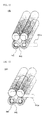
- FIG. 4 is a typical view illustrating a process to manufacture a battery cell core pack configured in a 2P-3S plane type structure according to an embodiment of the present invention.
- a battery cell core pack 100 is configured in a structure in which three banks 110, 120 and 130, each of which includes two vertically stacked cylindrical batteries, are arranged in the lateral direction thereof so as to be adjacent to each other. That is, the battery cell core pack 100 is configured in a 2 x 3 matrix type battery cell structure.
- the first bank 110 and the third bank 130 are erected so that cathode terminals of the first bank 110 and the third bank 130 are oriented forward, and the second bank 120 is erected in the direction opposite to the direction in which the first bank 110 and the third bank 130 are erected so that anode terminals of the second bank 120 are oriented forward.
- a first connecting member 162 and a second connecting member 70 are mounted to the front electrode terminals of the banks 110, 120 and 130.
- the first connecting member 162 formed in a planar quadrangular shape, electrically connects the cathode terminals of the first bank 110 and the anode terminals of the second bank 120 in parallel to each other. Also, the first connecting member 162 electrically connects the cathode terminals of the first bank 110 and the anode terminals of the second bank 120 in series to each other.
- the second connecting member 170 formed in a planar quadrangular shape, electrically connects the cathode terminals of the third bank 130 in parallel to each other.
- a third connecting member (not shown), formed in the same shape as the first connecting member 162, electrically connects anode terminals of the third bank 130 and cathode terminals of the second bank 120 in series to each other
- a fourth connecting member (not shown), formed in the same shape as the second connecting member 170, electrically connects anode terminals of the first bank 110 in parallel to each other.
- the first bank 110 is perpendicularly bent forward from the middle of the first connecting member 162 and is perpendicularly bent backward from the middle of the third connecting member (not shown), thereby manufacturing a battery cell core pack configured in a 2P - 3S plane type structure.
- first connecting member 162 and the third connecting member are formed in the planar square shape, as previously described, and therefore, the first connecting member 162 and the third connecting member can be easily coupled to the electrode terminals of the battery cells arranged in a 2 x 2 matrix.
- the structure of the first connecting member 162 enables spot welding to be stably carried out and welding to be simultaneously at the corresponding regions in a limited space. Also, the connecting member is prevented from being broken during bending the connecting member since the size of the bent region of the connecting member is large.
- FIGS. 5 to 9 are plan views typically illustrating electrode terminal connecting members according to various embodiments of the present invention.
- an electrode terminal connecting member 160 includes a plate body, formed in a planar square shape, to simultaneously connect electrode terminals of battery cells arranged in a 2 x 2 matrix to each other and a bending guide groove 160a depressed inward from the middle of each side of the plate body.
- An electrode terminal connecting member 161 of FIG. 6 includes a bending guide groove 161 a formed at the middle of each side of a plate body and a notch 161b formed at the plate body on an imaginary line horizontally connecting the corresponding bending guide grooves 161a.
- the notch 161b may be a linear groove minutely formed at the plate body.
- the groove may be a singly continuous line or a plurality of discontinuous lines.
- An electrode terminal connecting member 162 of FIG. 7 includes a bending guide groove 162a formed at the middle of each side of a plate body and a slit 162c, formed at each corner of the plate body, by which resistance welding to a corresponding electrode terminal is easily carried out.
- An electrode terminal connecting member 163 of FIG. 8 is identical in structure to the electrode terminal connecting member 162 of FIG. 7 except that a circular through hole 163d, by which the electrode terminal connecting member 163 is easily bent, is formed at the center of a plate body.
- An electrode terminal connecting member 164 of FIG. 9 is identical in structure to the electrode terminal connecting member 162 of FIG. 7 except that a diamond through hole 164d, by which the electrode terminal connecting member 163 is easily bent, is formed at the center of a plate body.
- the through holes 163d and 164d reduce the size of the respective plate bodies to be bent, and therefore, the respective plate bodies can be easily bent.
- FIG. 10 is a typical view illustrating a battery cell core pack configured in a 2P-4S plane type structure according to another embodiment of the present invention.
- a battery cell core pack 200 is configured in a structure in which four banks 210, 220, 230 and 240, each of which includes two cylindrical batteries, are arranged in the lateral direction thereof, and electrode terminal connecting members 260 and 262 are coupled to the tops of electrode terminals of the respective banks 210, 220, 230 and 240 by spot welding.
- the first bank 210 and the third bank 230 are erected so that cathode terminals of the first bank 210 and the third bank 230 are oriented forward, and the second bank 220 and the fourth bank 240 are erected in the direction opposite to the direction in which the first bank 210 and the third bank 230 are erected so that anode terminals of the second bank 220 and the fourth bank 240 are oriented forward.
- the first connecting member 260 is coupled to the tops of the cathode terminals of the first bank 210 and to the tops of the anode terminals of the second bank 220.
- the second connecting member 262 formed in the same shape as the first connecting member 260, is coupled to the tops of the cathode terminals of the third bank 230 and to the tops of the anode terminals of the fourth bank 240.
- a third connecting member (not shown), formed in a rectangular shape, is coupled to the tops of cathode terminals of the fourth bank 240, and a fourth connecting member (not shown), formed in the same shape as the first connecting member 260, is coupled to coupled to the tops of cathode terminals of the second bank 220 and to the tops of anode terminals of the third bank 230.
- a fifth connecting member (not shown), formed in a rectangular shape, is coupled to the tops of anode terminals of the first bank 210.
- the banks 210, 220, 230 and 240 are electrically connected to each other in a 2P-4S structure.
- FIG. 11 is a typical view illustrating a battery cell core pack configured in a 3P-3S plane type structure according to another embodiment of the present invention.
- a battery cell core pack 300 is configured in a structure in which three banks 310, 320 and 330, each of which includes three cylindrical batteries, are arranged in the lateral direction thereof, and electrode terminal connecting members 360 and 370 are coupled to the tops of electrode terminals of the respective banks 310, 320 and 330 by spot welding.
- the structure of FIG. 11 is identical to that of FIG. 11 except that the structure of FIG. 11 is a 3P-3S plane type structure, and therefore, a detailed description thereof will not be given.
- FIGS. 12 and 13 are typical views illustrating electrode terminal connecting members, a protection circuit board (PCB) connection part of each of which protrude in one direction, according to other embodiments of the present invention.
- PCB protection circuit board
- cylindrical batteries 400 are arranged in a 2 x 2 matrix, and an electrode terminal connecting member includes a square plate body 440 having a bending guide groove 442 formed at the middle of each side thereof and a PCB connection part 440a protruding from the lower end of one side of the plate body 440.
- the electrode terminal connecting member electrically connects electrode terminals of the cylindrical batteries 400 to each other and, at the same time, electrically connects the electrode terminal of the cylindrical batteries 400 to a PCB (not shown).
- An electrode terminal connecting member of FIG. 13 is identical to that of FIG. 12 except that a PCB connection part 540a horizontally protrudes from the upper end of one side of a square plate body 540, having a bending guide groove 542 formed at the middle of each side thereof, to the right, and therefore, a detailed description thereof will not be given.
- the core packs 200, 300, 400 and 500 of FIGS. 10 to 13 may be modified into predetermined forms by bending the connecting members in the same manner as in FIG. 3 as needed.
- FIG. 14 is a typical view illustrating a battery cell core pack in which the electrode terminal connecting members, one of which is shown in FIG. 13 , are fitted in a PCB.
- a battery cell core pack 600 is configured so that which three banks 610, 620 and 630 are electrically connected to each other in a 3S - 2P structure, and electrode connecting members (not shown) are disposed between the respective banks 610, 620 and 630. Connection parts, protruding in one direction, are inserted through respective connecting coupling parts 682 of a PCB 680.
- FIG. 15 is a partial typical view illustrating a battery cell core pack in which electrode terminal connecting members, one of which is shown in FIG. 13 , are soldered to a PCB.
- connection parts 660 of electrode terminal connecting members are inserted through insertion holes 682 of a PCB 680, and ends of the respective connection parts 660 are coupled to coupling parts 684 of the PCB 680 by soldering.
- FIG. 16 is a partial typical view illustrating a battery cell core pack in which electrode terminal connecting members, one of which is shown in FIG. 13 , are resistance welded to a PCB.
- connection parts 660 of electrode terminal connecting members are inserted through insertion holes 682 of a PCB 680, ends 686 of the respective connection parts 660 are bent perpendicularly to the PCB 680, and the ends 686 are coupled to coupling parts 684 of the PCB 680 by spot welding.
- FIGS. 17 to 20 are partial typical views illustrating connection coupling parts formed at a PCB according to various embodiments of the present invention.
- a connection coupling part 700 includes a slit-shaped through hole 701, through which a connection part (not shown) of an electrode terminal connecting member is inserted, and a coupling part 702, having a predetermined width, formed at the outer circumference of the through hole 701 so as to be coupled to the end of the connection part of the electrode terminal connecting member by spot welding.
- a connection coupling part 710 includes an insertion hole 711 formed in a U shape open at the top thereof and a coupling part 712 configured to be coupled to the end of a connection part (not shown) of an electrode terminal connecting member inserted through the insertion hole 711.
- insertion holes 722 and 732 of connection coupling parts 720 and 730 are chamfered (721) or rounded (731) at opposite corners thereof so that a connection part (not shown) of an electrode terminal connecting member can be more easily inserted through the insertion holes.
- the coupling parts 702, 712, 722 and 732 are electrically connected to a protection circuit of the PCB.
- the coupling parts 702, 712, 722 and 732 may be made of a metal material.
- an electrode terminal connecting member is configured in a plate type structure in which electrode terminals of battery cells arranged in at least 2 x 2 matrix are connected to each other in a state in which the electrode terminal connecting member is not bent. Consequently, it is possible to stably couple the electrode terminal connecting member to the electrode terminals of the battery cells in a state in which the electrode terminal connecting member is correctly placed at the electrode terminals of the battery cells, thereby easily achieving electrical connection between the battery cells.
Landscapes
- Chemical & Material Sciences (AREA)
- Chemical Kinetics & Catalysis (AREA)
- Electrochemistry (AREA)
- General Chemical & Material Sciences (AREA)
- Engineering & Computer Science (AREA)
- Manufacturing & Machinery (AREA)
- Microelectronics & Electronic Packaging (AREA)
- Connection Of Batteries Or Terminals (AREA)
- Battery Mounting, Suspending (AREA)
Abstract
Description
- The present invention relates to an electrode terminal connecting member used to manufacture a core pack, and, more particularly, to an electrode terminal connecting member to connect two or more battery cells in series and/or in parallel to each other so as to manufacture a battery cell core pack, wherein the electrode terminal connecting member includes a plate body having a size sufficient to connect electrode terminals of the battery cells arranged in at least 2 x 2 matrix to each other, and the electrode terminals of the battery cells are directly coupled to the plate body in a state in which the plate body is not bent.
- As mobile devices have been increasingly developed, and the demand for such mobile devices has increased, the demand for secondary batteries has also sharply increased. Among such secondary batteries is a lithium secondary battery exhibiting high energy density and operating voltage and excellent preservation and service-life characteristics, which has been widely used as an energy source for various electronic products as well as for the mobile devices.
- Depending upon kinds of external devices in which secondary batteries are used, the secondary batteries may be used in the form of a single battery or in the form of a battery pack having a plurality of unit cells electrically connected to one another. For example, small-sized devices, such as mobile phones, can be operated for a predetermined period of time with the power and the capacity of one battery. On the other hand, a battery pack needs to be used in middle or large-sized devices, such as laptop computers, portable digital versatile disc (DVD) players, small-sized personal computers (PCs), electric vehicles and hybrid electric vehicles, because high power and large capacity are necessary for the middle or large-sized devices.
- A battery pack is manufactured by connecting a protection circuit to a core pack having a plurality of unit cells connected in series and/or in parallel to each other. In a case in which prismatic batteries or pouch-shaped batteries are used as the unit cells, the prismatic batteries or the pouch-shaped batteries are stacked so that large-sized surfaces of the prismatic batteries or the pouch-shaped batteries face each other, and then electrode terminals of the prismatic batteries or the pouch-shaped batteries are connected to each other by connecting members, such as bus bars. In a case in which a three-dimensional battery pack having a hexahedral structure is to be manufactured, therefore, the prismatic batteries or the pouch-shaped batteries are preferably used as unit cells of the battery pack.
- On the other hand, cylindrical batteries generally have larger electric capacities than the prismatic batteries or the pouch-shaped batteries. However, it is difficult to arrange the cylindrical batteries in a stacked structure due to the external shape of the cylindrical batteries. In a case in which a battery pack is configured generally in a line type structure or in a plane type structure, though, the cylindrical batteries are structurally more advantageous than the prismatic batteries or the pouch-shaped batteries.
- Consequently, a battery pack having a plurality of cylindrical batteries connected in parallel and series to each other is widely used in laptop computers, portable DVD players, and portable PCs. The battery pack may be configured in various core pack structures. For example, the core pack of the battery pack may be generally configured in a 2P (parallel) - 3S (series) line type structure, a 2P - 3S plane type structure, a 2P - 4S line type structure or a 2P - 4S plane type structure.
- The parallel connection structure is achieved by arranging two or more cylindrical batteries in the lateral direction thereof so that the cylindrical batteries are adjacent to each other in a state in which electrode terminals of the cylindrical batteries are oriented in the same direction and connecting the electrode terminals of the cylindrical batteries to each other via connecting members by welding. The cylindrical batteries connected in parallel to each other may be referred to as a "bank."
- The series connection structure is achieved by arranging two or more cylindrical batteries in the longitudinal direction thereof so that electrode terminals of the cylindrical batteries having opposite polarities are successively disposed one after another, or arranging two or more cylindrical batteries in the lateral direction thereof so that the cylindrical batteries are adjacent to each other in a state in which electrode terminals of the cylindrical batteries are oriented in opposite directions, and connecting the electrode terminals of the cylindrical batteries to each other via connecting members by welding.
- The electrical connection between the cylindrical batteries is generally achieved by spot welding using thin plane type connecting members, such as nickel plates. Also, a protection circuit is connected to a core pack manufactured by connecting cylindrical batteries in parallel and/or in series to each other to manufacture a battery pack.
-
FIGS. 1 to 3 typically illustrate a series of processes to manufacture a core pack configured in a 2P-3S plane type structure using a conventional plane type connecting member. - Referring first to
FIGS. 1 and 2 , in order to manufacture acore pack 50 configured in a 2P-3S plane type structure, a total of 6cylindrical batteries 10, as unit cells, are arranged in the lateral direction thereof to form threebanks - In order to manufacture the
core pack 50, first, thefirst bank 11 and thethird bank 13 are disposed so that cathode terminals of thefirst bank 11 and thethird bank 13 3 are oriented forward, and thesecond bank 12 is disposed in the direction opposite to the direction in which thefirst bank 11 and thethird bank 13 are disposed so that anode terminals of thesecond bank 12 are oriented forward. - Subsequently, spot welding is carried out at the fronts (see
FIG. 1 ) of theunit cells 10 in a state in which a first connectingmember 16 is placed at the cathode terminals of thefirst bank 11, a second connecting member 17 is placed over the anode terminals of thesecond bank 12 and the cathode terminals of thethird bank 13, thereby achieving the coupling between the connectingmembers 16 and 17 and the electrode terminals located at the fronts of theunit cells 10. - Subsequently, spot welding is carried out at the rears (see
FIG. 2 ) of theunit cells 10 in a state in which a third connecting member 18 is placed over the anode terminals of thefirst bank 11 and the cathode terminals of thesecond bank 12, and a fourth connectingmember 19 is placed at the anode terminals of thethird bank 13, thereby achieving the coupling between connectingmembers 18 and 19 and the electrode terminals located at the rears of theunit cells 10. - Referring to
FIG. 3 together withFIGS. 1 and 2 , thethird bank 13 is perpendicularly bent forward from the middle of the second connecting member 17, and thefirst bank 11 is perpendicularly bent rearward from the middle of the third connecting member 18, thereby manufacturing a core pack configured in a 2P - 3S plane type structure. For information, P (parallel) indicates electrical parallel connection and S (series) indicated electrical series connection. - However, plane type connecting members are generally configured in a long bar type structure. In a case in which a plurality of cylindrical batteries arranged in the lateral direction thereof so that the cylindrical batteries are adjacent to each other is connected to each other via such plane type connecting members, it is difficult to carry out welding in a state in which the plane type connecting members are correctly placed at electrode terminals disposed at the tops and bottoms of the cylindrical batteries.
- Also, when two or more cylindrical batteries are arranged in the lateral direction thereof so as to be adjacent to each other in a state in which electrode terminals of the cylindrical batteries are oriented in opposite directions, the electrode a terminals of the cylindrical batteries are connected to each other via a general long bar type connecting member, and the connection portion is bent in order to connect the cylindrical batteries in series to each other, it is difficult to accurately and stably bent the cylindrical batteries in a linear series structure and the bent portion may be broken since the width and thickness of the connecting member at the bent portion are thin.
- That is, in a case in which a plurality of cylindrical batteries is connected to each other using a general plane type connecting member, it is difficult and complicated to connect the cylindrical batteries, thereby greatly lowering manufacturing efficiency of a battery pack.
- In connection with this case, research has been conducted on technology to improve assembly efficiency of a battery pack. For example, Japanese Patent Application Publication No.
2001-325931 - In the structure of the assembly battery, however, the electrically insulative resin material in which the metal connection members are buried with the result that the volume and weight of a battery pack are increased. Consequently, the battery cell receiving space of the battery pack is reduced, and energy density of the battery pack per unit volume is lowered.
- Also, Japanese Patent Application Publication No.
2001-325931 - However, it is difficult to use the connecting member for batteries in a case in which three or more cylindrical batteries are connected in series to each other. Also, the connecting member includes the first connection part and the second connection part. Consequently, a process to manufacture the connecting member is complicated, and productivity of a battery pack is lowered.
- Consequently, there is a high necessity for technology to easily and efficiently achieve electrical connection between battery cells, thereby improving manufacturing efficiency and productivity of a battery pack while solving the above conventional problems.
- Therefore, the present invention has been made to solve the above problems, and other technical problems that have yet to be resolved.
- As the result of a variety of extensive and intensive studies and experiments to solve the problems as described above, the inventors of the present application have developed an electrode terminal connecting member including a plate body having a size sufficient to connect electrode terminals of battery cells arranged in at least 2 x 2 matrix to each other, wherein the electrode terminals of the battery cells are directly coupled to the plate body in a state in which the plate body is not bent, thereby simply and easily achieving the connection between the battery cells, and have found that it is possible to improve manufacturing efficiency and productivity of a battery pack through use of such an electrode terminal connecting member.
- Therefore, it is an object of the present invention to provide an electrode terminal connecting member to simply and easily connect two or more battery cells in series and/or in parallel to each other, thereby improving productivity of a core pack and a battery pack.
- In accordance with one aspect of the present invention, the above and other objects can be accomplished by the provision of an electrode terminal connecting member to connect two or more battery cells in series and/or in parallel to each other so as to manufacture a battery cell core pack, wherein the electrode terminal connecting member includes a plate body having a size sufficient to connect electrode terminals of the battery cells arranged in at least 2 x 2 matrix to each other, and the electrode terminals of the battery cells are directly coupled to the plate body in a state in which the plate body is not bent.
- That is, the electrode terminal connecting member according to the present invention is configured in a plate type structure in which electrode terminals of battery cells arranged in at least 2 x 2 matrix are connected to each other in a state in which the electrode terminal connecting member is not bent. When a plurality of battery cells is electrically connected to each other, therefore, it is possible to stably couple the electrode terminal connecting member to the electrode terminals of the battery cells in a state in which the electrode terminal connecting member is correctly placed at the electrode terminals of the battery cells, thereby efficiently achieving electrical connection between the battery cells.
- Also, in a case in which core packs each including a large number of connected battery cells are mass-produced, automatic production of the core packs is possible, thereby greatly improving manufacturing efficiency and productivity of battery packs. For example, when the connecting member is coupled to the electrode terminals of the battery cells by welding, the size of a welding apparatus may be reduced, and a plurality of welding operations may be simultaneously carried out.
- A core pack may be configured in a structure in which the row and column of the battery cells are maintained in a state in which the plate body is coupled to the electrode terminals of the respective battery cells. As needed, a core pack may be configured in a structure in which the row and column of the battery cells are changed in a state in which the plate body is coupled to the electrode terminals of the respective battery cells.
- In a preferred example, the electrode terminal connecting member may be configured so that the plate body is provided at the edge thereof with inwardly depressed bending guide grooves, by which the plate body is bent in the row or column direction of the battery cells after the electrode terminals of the battery cells are coupled to the plate body.
- Since the bending guide grooves are formed at the edge of the plate body of the electrode terminal connecting member, it is possible to easily bend the plate body in the row or column direction of desired battery cells or banks using even small force when the plate body is bent in a state in which the plate body is welded to electrode terminals of the battery cells or banks.
- The shape of the plate body is not particularly restricted so long as the plate body can easily connect electrode terminals of battery cells arranged in at least 2 x 2 matrix are connected to each other. Preferably, the plate body is formed in a planar square or rectangular shape.
- The connection between the electrode terminal connecting member and the battery cells or the banks is mainly achieved by welding. For example, the connection between the electrode terminal connecting member and the battery cells or the banks may be achieved by resistance welding, to which, however, the present invention is not limited. In this case, the plate body of the electrode terminal connecting member is preferably further provided with a slit, through which the plate body is easily resistance welded to the electrode terminals of the battery cells or the banks. For example, the slit may be a thin and long through hole.
- In the structure of the electrode terminal connecting member having the bending guide grooves formed at the edge of the plate body as described above, as an example, the plate body may be further provided with a structure to easily bend the plate body. For example, the plate body may be further provided with a notch formed on an imaginary line vertically and/or horizontally connecting the respective bending guide grooves.
- The notch serves to facilitate the electrode terminal connecting member to be bent and, at the same time, to guide the electrode terminal connecting member so that the electrode terminal connecting member can be correctly and stably bent.
- As another example of the above structure, the plate body, at which the bending guide grooves are formed, may be further provided at the center thereof with a through hole so that the plate body can be easily bent by through hole. The shape of the through hole is not particularly restricted so long as the plate body can be easily bent by the through hole. Preferably, the through hole is formed in a planar circular or diamond shape.
- Therefore, it is possible to more easily bend the plate body in the row or column direction of the battery cells or the banks in a state in which the battery cells or the banks are welded to the plate body by the notch and/or the through hole further formed at the plate body in the vicinity of the bending guide grooves.
- Meanwhile, a battery pack is manufactured by connecting a protection circuit to a core pack including battery cells connected in parallel and/or in series to each other. Preferably, therefore, the core pack constituting the battery pack is configured in a circuit structure in which the core pack is connected to the battery cells and, at the same time, connected to a protection circuit board.
- In order to achieve such a circuit configuration, therefore, the plate body of the electrode terminal connecting member may be provided at the edge thereof with a protection circuit board (PCB) connection part protruding in one direction.
- The plate body may be formed of a nickel plate made of nickel exhibiting electrical conductivity, to which, however, the present invention is not limited.
- Various forms of batteries may be used as the battery cells. For example, each of the battery cells may be a cylindrical battery or a prismatic battery. Preferably, each of the battery cells is a cylindrical battery.
- Generally, a cylindrical battery is configured in a structure in which a cathode terminal protrude from one end of the cylindrical battery, and the entirety of a battery case forms an anode terminal in a state in which the battery case is insulated from the cathode terminal. In a case in which cathode terminals of unit cells arranged in the lateral direction thereof, i.e. a bank, therefore, it is preferable to weld the metal plate to the cathode terminals of the bank in a state in which an insulation sheet is disposed to cover the top of the bank so that only the cathode terminals are exposed to the outside.
- In accordance with another aspect of the present invention, there is provided a battery cell core pack wherein an electrode terminal connecting member with the above-stated construction is connected to a PCB.
- In a preferred example, the battery cell core pack may be configured in a structure in which the electrode terminal connecting member electrically connecting the electrode terminals of the battery cells is directly connected to the protection circuit board. Consequently, it is possible to easily achieve automation, thereby greatly improving productivity and quality, as compared with a conventional method of manually achieving the electrical connection between the electrode terminals of the battery cells and the protection circuit board using a wire.
- In a concrete example, a plate body of the electrode terminal connecting member may be provided at the edge thereof with a PCB connection part protruding in one direction, and the PCB may be provided with a connection coupling part into which the connection part is inserted and coupled.
- The structure of the connection coupling part is not particularly restricted so long as the connection part is easily into the connection coupling part. Preferably, the connection coupling part includes an insertion hole through which the connection part is inserted and coupling part to which an end of the inserted connection part is coupled, the coupling part being formed along the outer circumference of the insertion hole so as to have a predetermined width.
- In the above structure, the shape of the insertion hole is not particularly restricted so long as the connection part of the electrode terminal connecting member can be easily inserted through the insertion hole. For example, the insertion hole may be a slit-shaped through hole or may be formed in a U shape open at the top thereof.
- In a case in which the insertion hole is formed in such a U shape, the U-shaped insertion hole may be chamfered or rounded at opposite corners thereof so that the connection part of the electrode terminal connecting member can be easily inserted through the insertion hole from above.
- Meanwhile, the coupling between the connection part of the electrode terminal connecting member and the protection circuit board may be achieved in various ways. For example, the coupling between the connection part of the electrode terminal connecting member and the protection circuit board may be achieved by soldering or welding.
- The welding may include laser welding or resistance welding, which achieves stable coupling between the battery cells and the protection circuit board without damage to or deformation of the battery cells and the protection circuit board. Preferably, the welding includes spot welding or seam welding.
- Generally, automation is easily achieved using laser welding and resistance welding as compared with soldering. For information, laser welding is a method of melting metal using laser beams to achieve welding, and resistance welding is a method of supplying electric current to a welding base material to heat the welding base material using heat generated by contact resistance at a joint so that the welding base material is molten, and applying mechanical pressure to achieve welding.
- In accordance with another aspect of the present invention, there is provided a battery pack including a battery cell core pack with the above-stated construction mounted in a pack case.
- Kinds of devices for which the battery pack is used as a power source are not particularly restricted. Preferably, the battery pack is used as a power source for laptop computers.
- In accordance with a further aspect of the present invention, there is provided a method of manufacturing a battery cell core pack by connecting two or more battery cells in series and/or in parallel to each other.
- Specifically, the manufacturing method includes (a) welding an electrode terminal connecting member including a plate body having a size sufficient to connect electrode terminals of the battery cells arranged in at least 2 x 2 matrix to each other and inwardly depressed bending guide grooves formed at the edge of the plate body to the electrode terminals of the battery cells, (b) bending the electrode terminal connecting member along the bending guide grooves to arrange the battery cells in a line, (c) inserting a connection part protruding from the edge of the plate body in one direction through a connection coupling part of a protection circuit board formed in a shape corresponding to the connection part, (d) bending an end of the connection part protruding outward from the connection coupling part of the protection circuit board, and (e) soldering or welding the bent end of the connection part to a coupling part of the protection circuit board.
- In the method of manufacturing the battery cell core pack according to the present invention, as described above, an electrode terminal connecting member including a plate body having a size sufficient to connect electrode terminals of the battery cells arranged in at least 2 x 2 matrix to each other and inwardly depressed bending guide grooves formed at the edge of the plate body to the electrode terminals of the battery cells is welded to the electrode terminals of the battery cells and is then bent. Consequently, it is possible to more simply and easily manufacture a core pack configured in a structure in which battery cells are in series and/or in parallel to each other in various ways.
- Also, after the end of the connection part of the plate body is inserted into the connection coupling part of the protection circuit board, the coupling between the connection part of the plate body is simply coupled to the connection coupling part of the protection circuit board, thereby achieving the coupling between the battery cells and the protection circuit board. Consequently, it is possible to easily achieve automation, thereby greatly improving productivity, as compared with a conventional method of achieving the connection between the battery cells and the protection circuit board using a wire.
- The above and other objects, features and other advantages of the present invention will be more clearly understood from the following detailed description taken in conjunction with the accompanying drawings, in which:
-
FIGS. 1 to 3 are typical views illustrating a series of processes to manufacture a battery cell core pack configured in a 2P-3S plane type structure using a conventional plane type connecting member; -
FIG. 4 is a typical view illustrating a process to manufacture a battery cell core pack configured in a 2P-3S plane type structure according to an embodiment of the present invention; -
FIGS. 5 to 9 are plan views typically illustrating electrode terminal connecting members according to various embodiments of the present invention; -
FIG. 10 is a typical view illustrating a battery cell core pack configured in a 2P-4S plane type structure according to another embodiment of the present invention; -
FIG. 11 is a typical view illustrating a battery cell core pack configured in a 3P-3S plane type structure according to another embodiment of the present invention; -
FIGS. 12 and 13 are typical views illustrating electrode terminal connecting members, a protection circuit board (PCB) connection part of each of which protrude in one direction, according to other embodiments of the present invention; -
FIG. 14 is a typical view illustrating a battery cell core pack in which electrode terminal connecting members, one of which is shown inFIG. 13 , are fitted in a PCB; -
FIG. 15 is a partial typical view illustrating a battery cell core pack in which electrode terminal connecting members, one of which is shown inFIG. 13 , are soldered to a PCB; -
FIG. 16 is a partial typical view illustrating a battery cell core pack in which electrode terminal connecting members, one of which is shown inFIG. 13 , are resistance welded to a PCB; and -
FIGS. 17 to 20 are partial typical views illustrating connection coupling parts formed at a PCB according to various embodiments of the present invention. - Now, preferred embodiments of the present invention will be described in detail with reference to the accompanying drawings. It should be noted, however, that the scope of the present invention is not limited by the illustrated embodiments. For easy understanding, some of the drawings are shown as partial see-through views.
-
FIG. 4 is a typical view illustrating a process to manufacture a battery cell core pack configured in a 2P-3S plane type structure according to an embodiment of the present invention. - Referring to
FIG. 4 , a batterycell core pack 100 is configured in a structure in which threebanks cell core pack 100 is configured in a 2 x 3 matrix type battery cell structure. - The
first bank 110 and thethird bank 130 are erected so that cathode terminals of thefirst bank 110 and thethird bank 130 are oriented forward, and thesecond bank 120 is erected in the direction opposite to the direction in which thefirst bank 110 and thethird bank 130 are erected so that anode terminals of thesecond bank 120 are oriented forward. A first connectingmember 162 and a second connecting member 70 are mounted to the front electrode terminals of thebanks - The first connecting
member 162, formed in a planar quadrangular shape, electrically connects the cathode terminals of thefirst bank 110 and the anode terminals of thesecond bank 120 in parallel to each other. Also, the first connectingmember 162 electrically connects the cathode terminals of thefirst bank 110 and the anode terminals of thesecond bank 120 in series to each other. The second connectingmember 170, formed in a planar quadrangular shape, electrically connects the cathode terminals of thethird bank 130 in parallel to each other. - Also, at the rear (not shown) of the battery cell structure, a third connecting member (not shown), formed in the same shape as the first connecting
member 162, electrically connects anode terminals of thethird bank 130 and cathode terminals of thesecond bank 120 in series to each other, and a fourth connecting member (not shown), formed in the same shape as the second connectingmember 170, electrically connects anode terminals of thefirst bank 110 in parallel to each other. - In this coupled state, the
first bank 110 is perpendicularly bent forward from the middle of the first connectingmember 162 and is perpendicularly bent backward from the middle of the third connecting member (not shown), thereby manufacturing a battery cell core pack configured in a 2P - 3S plane type structure. - Also, the first connecting
member 162 and the third connecting member (not shown) are formed in the planar square shape, as previously described, and therefore, the first connectingmember 162 and the third connecting member can be easily coupled to the electrode terminals of the battery cells arranged in a 2 x 2 matrix. - In addition, the structure of the first connecting
member 162 enables spot welding to be stably carried out and welding to be simultaneously at the corresponding regions in a limited space. Also, the connecting member is prevented from being broken during bending the connecting member since the size of the bent region of the connecting member is large. -
FIGS. 5 to 9 are plan views typically illustrating electrode terminal connecting members according to various embodiments of the present invention. - Referring first to
FIG. 5 , an electrodeterminal connecting member 160 includes a plate body, formed in a planar square shape, to simultaneously connect electrode terminals of battery cells arranged in a 2 x 2 matrix to each other and a bending guide groove 160a depressed inward from the middle of each side of the plate body. - An electrode
terminal connecting member 161 ofFIG. 6 includes a bendingguide groove 161 a formed at the middle of each side of a plate body and a notch 161b formed at the plate body on an imaginary line horizontally connecting the corresponding bendingguide grooves 161a. The notch 161b may be a linear groove minutely formed at the plate body. The groove may be a singly continuous line or a plurality of discontinuous lines. - An electrode
terminal connecting member 162 ofFIG. 7 includes a bending guide groove 162a formed at the middle of each side of a plate body and aslit 162c, formed at each corner of the plate body, by which resistance welding to a corresponding electrode terminal is easily carried out. - An electrode
terminal connecting member 163 ofFIG. 8 is identical in structure to the electrodeterminal connecting member 162 ofFIG. 7 except that a circular throughhole 163d, by which the electrodeterminal connecting member 163 is easily bent, is formed at the center of a plate body. An electrodeterminal connecting member 164 ofFIG. 9 is identical in structure to the electrodeterminal connecting member 162 ofFIG. 7 except that a diamond throughhole 164d, by which the electrodeterminal connecting member 163 is easily bent, is formed at the center of a plate body. The throughholes -
FIG. 10 is a typical view illustrating a battery cell core pack configured in a 2P-4S plane type structure according to another embodiment of the present invention. - Referring to
FIG. 10 , a batterycell core pack 200 is configured in a structure in which fourbanks terminal connecting members respective banks - The
first bank 210 and thethird bank 230 are erected so that cathode terminals of thefirst bank 210 and thethird bank 230 are oriented forward, and thesecond bank 220 and thefourth bank 240 are erected in the direction opposite to the direction in which thefirst bank 210 and thethird bank 230 are erected so that anode terminals of thesecond bank 220 and thefourth bank 240 are oriented forward. - At the fronts of the
banks member 260 is coupled to the tops of the cathode terminals of thefirst bank 210 and to the tops of the anode terminals of thesecond bank 220. Also, the second connectingmember 262, formed in the same shape as the first connectingmember 260, is coupled to the tops of the cathode terminals of thethird bank 230 and to the tops of the anode terminals of thefourth bank 240. - At the rear (not shown) of such a battery cell structure, on the other hand, a third connecting member (not shown), formed in a rectangular shape, is coupled to the tops of cathode terminals of the
fourth bank 240, and a fourth connecting member (not shown), formed in the same shape as the first connectingmember 260, is coupled to coupled to the tops of cathode terminals of thesecond bank 220 and to the tops of anode terminals of thethird bank 230. Also, a fifth connecting member (not shown), formed in a rectangular shape, is coupled to the tops of anode terminals of thefirst bank 210. - In the above structure, therefore, the
banks -
FIG. 11 is a typical view illustrating a battery cell core pack configured in a 3P-3S plane type structure according to another embodiment of the present invention. - Referring to
FIG. 11 , a batterycell core pack 300 is configured in a structure in which threebanks terminal connecting members respective banks FIG. 11 is identical to that ofFIG. 11 except that the structure ofFIG. 11 is a 3P-3S plane type structure, and therefore, a detailed description thereof will not be given. -
FIGS. 12 and 13 are typical views illustrating electrode terminal connecting members, a protection circuit board (PCB) connection part of each of which protrude in one direction, according to other embodiments of the present invention. - Referring first to
FIG. 12 ,cylindrical batteries 400 are arranged in a 2 x 2 matrix, and an electrode terminal connecting member includes asquare plate body 440 having a bendingguide groove 442 formed at the middle of each side thereof and aPCB connection part 440a protruding from the lower end of one side of theplate body 440. - Therefore, the electrode terminal connecting member electrically connects electrode terminals of the
cylindrical batteries 400 to each other and, at the same time, electrically connects the electrode terminal of thecylindrical batteries 400 to a PCB (not shown). - An electrode terminal connecting member of
FIG. 13 is identical to that ofFIG. 12 except that aPCB connection part 540a horizontally protrudes from the upper end of one side of asquare plate body 540, having a bendingguide groove 542 formed at the middle of each side thereof, to the right, and therefore, a detailed description thereof will not be given. - The core packs 200, 300, 400 and 500 of
FIGS. 10 to 13 may be modified into predetermined forms by bending the connecting members in the same manner as inFIG. 3 as needed. -
FIG. 14 is a typical view illustrating a battery cell core pack in which the electrode terminal connecting members, one of which is shown inFIG. 13 , are fitted in a PCB. - Referring to
FIG. 14 , a batterycell core pack 600 is configured so that which threebanks respective banks coupling parts 682 of aPCB 680. -
FIG. 15 is a partial typical view illustrating a battery cell core pack in which electrode terminal connecting members, one of which is shown inFIG. 13 , are soldered to a PCB. - Referring to
FIG. 15 ,connection parts 660 of electrode terminal connecting members are inserted throughinsertion holes 682 of aPCB 680, and ends of therespective connection parts 660 are coupled tocoupling parts 684 of thePCB 680 by soldering. -
FIG. 16 is a partial typical view illustrating a battery cell core pack in which electrode terminal connecting members, one of which is shown inFIG. 13 , are resistance welded to a PCB. - Referring to
FIG. 16 ,connection parts 660 of electrode terminal connecting members are inserted throughinsertion holes 682 of aPCB 680, ends 686 of therespective connection parts 660 are bent perpendicularly to thePCB 680, and theends 686 are coupled tocoupling parts 684 of thePCB 680 by spot welding. -
FIGS. 17 to 20 are partial typical views illustrating connection coupling parts formed at a PCB according to various embodiments of the present invention. - Referring first to
FIG. 17 , aconnection coupling part 700 includes a slit-shaped throughhole 701, through which a connection part (not shown) of an electrode terminal connecting member is inserted, and acoupling part 702, having a predetermined width, formed at the outer circumference of the throughhole 701 so as to be coupled to the end of the connection part of the electrode terminal connecting member by spot welding. - Referring to
FIG. 18 , aconnection coupling part 710 includes aninsertion hole 711 formed in a U shape open at the top thereof and acoupling part 712 configured to be coupled to the end of a connection part (not shown) of an electrode terminal connecting member inserted through theinsertion hole 711. - Referring to
FIGS. 19 and 20 , insertion holes 722 and 732 ofconnection coupling parts - The
coupling parts coupling parts - As is apparent from the above description, an electrode terminal connecting member according to the present invention is configured in a plate type structure in which electrode terminals of battery cells arranged in at least 2 x 2 matrix are connected to each other in a state in which the electrode terminal connecting member is not bent. Consequently, it is possible to stably couple the electrode terminal connecting member to the electrode terminals of the battery cells in a state in which the electrode terminal connecting member is correctly placed at the electrode terminals of the battery cells, thereby easily achieving electrical connection between the battery cells.
- Also, in a case in which core packs each including a large number of variously connected batteries are mass-produced, automation is possible, thereby greatly improving manufacturing efficiency and productivity of battery packs.
- Although the preferred embodiments of the present invention have been disclosed for illustrative purposes, those skilled in the art will appreciate that various modifications, additions and substitutions are possible, without departing from the scope and spirit of the invention as disclosed in the accompanying claims.
Claims (20)
- An electrode terminal connecting member to connect two or more battery cells in series and/or in parallel to each other so as to manufacture a battery cell core pack, wherein the electrode terminal connecting member comprises a plate body having a size sufficient to connect electrode terminals of the battery cells arranged in at least 2 x 2 matrix to each other, and the electrode terminals of the battery cells are directly coupled to the plate body in a state in which the plate body is not bent.
- The electrode terminal connecting member according to claim 1, wherein the plate body is provided at the edge thereof with inwardly depressed bending guide grooves, by which the plate body is bent in a row or column direction of the battery cells after the electrode terminals of the battery cells are coupled to the plate body.
- The electrode terminal connecting member according to claim 1, wherein the plate body is formed in a planar square or rectangular shape.
- The electrode terminal connecting member according to claim 1, wherein the plate body is further provided with a slit, through which the plate body is easily resistance welded to the electrode terminals of the battery cells.
- The electrode terminal connecting member according to claim 2, wherein the plate body is further provided with a notch formed on an imaginary line vertically and/or horizontally connecting the respective bending guide grooves so that the plate body is easily bent by the notch.
- The electrode terminal connecting member according to claim 2, wherein the plate body is further provided at the center thereof with a through hole so that the plate body is easily bent by through hole.
- The electrode terminal connecting member according to claim 6, wherein the through hole is formed in a planar circular or diamond shape.
- The electrode terminal connecting member according to claim 1, wherein the plate body is provided at the edge thereof with a protection circuit board (PCB) connection part protruding in one direction.
- The electrode terminal connecting member according to claim 1, wherein the plate body is formed of a nickel plate.
- The electrode terminal connecting member according to claim 1, wherein each of the battery cells is a cylindrical battery.
- A battery cell core pack wherein an electrode terminal connecting member according to any one of claims 1 to 10 is connected to a PCB.
- The battery cell core pack according to claim 11, wherein a plate body of the electrode terminal connecting member is provided at the edge thereof with a PCB connection part protruding in one direction, and the PCB is provided with a connection coupling part into which the connection part is inserted and coupled.
- The battery cell core pack according to clam 12, wherein the connection coupling part comprises an insertion hole through which the connection part is inserted and coupling part to which an end of the inserted connection part is coupled, the coupling part being formed along the outer circumference of the insertion hole so as to have a predetermined width.
- The battery cell core pack according to claim 13, wherein the insertion hole is a slit-shaped through hole or is formed in a U shape open at the top thereof.
- The battery cell core pack according to claim 14, wherein the U-shaped insertion hole is chamfered or rounded at opposite corners thereof so that a connection part of the electrode terminal connecting member can be easily inserted through the insertion hole from above.
- The battery cell core pack according to claim 11, wherein the coupling between a connection part of the electrode terminal connecting member and the PCB is achieved by soldering or welding.
- The battery cell core pack according to claim 16, wherein the welding comprises spot welding or seam welding.
- A battery pack comprising a battery cell core pack according to claim 11 mounted in a pack case.
- The battery pack according to claim 18, wherein the battery pack is used as a power source for laptop computers.
- A method of manufacturing a battery cell core pack by connecting two or more battery cells in series and/or in parallel to each other, wherein the manufacturing method comprises:(a) welding an electrode terminal connecting member comprising a plate body having a size sufficient to connect electrode terminals of the battery cells arranged in at least 2 x 2 matrix to each other and inwardly depressed bending guide grooves formed at the edge of the plate body to the electrode terminals of the battery cells;(b) bending the electrode terminal connecting member along the bending guide grooves to arrange the battery cells in a line;(c) inserting a connection part protruding from the edge of the plate body in one direction through a connection coupling part of a protection circuit board formed in a shape corresponding to the connection part;(d) bending an end of the connection part protruding outward from the connection coupling part of the protection circuit board; and(e) soldering or welding the bent end of the connection part to a coupling part of the protection circuit board.
Applications Claiming Priority (2)
| Application Number | Priority Date | Filing Date | Title |
|---|---|---|---|
| KR1020080100712A KR101198869B1 (en) | 2008-10-14 | 2008-10-14 | Connecting Member of Electrode Terminals for Preparation of Core Pack |
| PCT/KR2009/005869 WO2010044588A2 (en) | 2008-10-14 | 2009-10-13 | Electrode terminal connection member for producing a core pack |
Publications (3)
| Publication Number | Publication Date |
|---|---|
| EP2337116A2 true EP2337116A2 (en) | 2011-06-22 |
| EP2337116A4 EP2337116A4 (en) | 2014-01-01 |
| EP2337116B1 EP2337116B1 (en) | 2018-05-09 |
Family
ID=42107039
Family Applications (1)
| Application Number | Title | Priority Date | Filing Date |
|---|---|---|---|
| EP09820738.4A Active EP2337116B1 (en) | 2008-10-14 | 2009-10-13 | Electrode terminal connection member for producing a core pack |
Country Status (6)
| Country | Link |
|---|---|
| US (1) | US10090503B2 (en) |
| EP (1) | EP2337116B1 (en) |
| JP (1) | JP5373091B2 (en) |
| KR (1) | KR101198869B1 (en) |
| CN (2) | CN105336908A (en) |
| WO (1) | WO2010044588A2 (en) |
Cited By (6)
| Publication number | Priority date | Publication date | Assignee | Title |
|---|---|---|---|---|
| WO2013059235A1 (en) * | 2011-10-19 | 2013-04-25 | Cobasys, Llc | Fusible link to connect battery cells and modules |
| EP2680344A1 (en) * | 2012-06-28 | 2014-01-01 | Robert Bosch Gmbh | Hand tool rechargeable battery device |
| EP2757613A1 (en) * | 2013-01-22 | 2014-07-23 | Samsung SDI Co., Ltd. | Rechargeable battery pack |
| IT201800007408A1 (en) * | 2018-07-23 | 2020-01-23 | "BATTERY PACK FOR ELECTRIC BICYCLE" | |
| EP3605657A4 (en) * | 2017-10-11 | 2020-06-03 | LG Chem, Ltd. | BATTERY MODULE AND MANUFACTURING METHOD THEREOF |
| WO2023088818A1 (en) * | 2021-11-17 | 2023-05-25 | HELLA GmbH & Co. KGaA | Energy store, method for producing an energy store and vehicle |
Families Citing this family (25)
| Publication number | Priority date | Publication date | Assignee | Title |
|---|---|---|---|---|
| KR20100136107A (en) * | 2009-06-18 | 2010-12-28 | 삼성에스디아이 주식회사 | Battery pack |
| KR101101035B1 (en) * | 2009-11-18 | 2011-12-29 | 삼성에스디아이 주식회사 | Connection tab between battery cells and battery module using same |
| JP5496746B2 (en) * | 2010-03-31 | 2014-05-21 | 三洋電機株式会社 | Battery pack |
| US8785781B2 (en) * | 2010-06-21 | 2014-07-22 | Samsung Sdi Co., Ltd. | Connecting tab of battery pack, coupling structure between the connecting tab and wire, and coupling method thereof |
| US9276250B2 (en) * | 2010-08-26 | 2016-03-01 | Samsung Sdi Co., Ltd. | Battery array and battery pack having the same |
| KR101147236B1 (en) * | 2010-08-31 | 2012-05-18 | 삼성에스디아이 주식회사 | Rechargeable battery pack |
| KR101283347B1 (en) * | 2010-09-07 | 2013-07-10 | 주식회사 엘지화학 | High-Output, Large-Capacity Battery Pack |
| KR101219233B1 (en) * | 2010-11-19 | 2013-01-09 | 삼성에스디아이 주식회사 | Battery array and battery packs having same |
| WO2012147137A1 (en) * | 2011-04-28 | 2012-11-01 | トヨタ自動車株式会社 | Battery pack |
| CN103152982B (en) * | 2013-02-04 | 2015-12-09 | 山东润峰集团新能源科技有限公司 | Battery pack series-parallel rapid assembly PCB |
| KR102073193B1 (en) * | 2013-09-23 | 2020-02-04 | 삼성에스디아이 주식회사 | Battery Pack |
| KR20150065299A (en) * | 2013-12-05 | 2015-06-15 | 삼성에스디아이 주식회사 | Battery module |
| KR102285144B1 (en) * | 2015-01-30 | 2021-08-04 | 삼성에스디아이 주식회사 | Secondary battery |
| KR102459621B1 (en) * | 2015-12-28 | 2022-10-27 | 삼성에스디아이 주식회사 | Battery pack |
| KR101805546B1 (en) | 2016-03-08 | 2017-12-07 | 삼성에스디아이 주식회사 | Battery pack having connection tab with bent portion |
| KR102159263B1 (en) * | 2016-06-16 | 2020-09-23 | 주식회사 엘지화학 | Battery module, battery pack comprising the battery module and vehicle comprising the battery pack |
| KR102051927B1 (en) * | 2016-10-31 | 2019-12-04 | 주식회사 엘지화학 | Protection Circuit Board Capable of Easily Checking Welded State between Electrode Terminal and Connection Part thereof and Secondary Battery Pack Comprising the Same |
| EP3678211B1 (en) * | 2017-08-29 | 2023-09-27 | Panasonic Energy Co., Ltd. | Battery pack and method for manufacturing same |
| KR102321513B1 (en) * | 2018-08-21 | 2021-11-02 | 주식회사 엘지에너지솔루션 | Battery Module Having Bus-Bar Plate |
| JP7385807B2 (en) * | 2018-10-02 | 2023-11-24 | 株式会社オートネットワーク技術研究所 | Flexible printed circuit boards and wiring modules |
| JP7115553B2 (en) * | 2018-10-10 | 2022-08-09 | 株式会社村田製作所 | Power generation element mounting boards, battery packs, electronic devices and electric vehicles |
| DE102018218904A1 (en) * | 2018-11-06 | 2020-05-07 | Robert Bosch Gmbh | Method for producing a battery module comprising a plurality of battery module levels |
| KR102381962B1 (en) * | 2018-11-29 | 2022-04-01 | 주식회사 엘지에너지솔루션 | Battery Pack Having Heat Dissipating Member |
| CN110854322A (en) * | 2019-09-20 | 2020-02-28 | 杭州乾代科技有限公司 | Modularized lithium battery module |
| WO2022170484A1 (en) * | 2021-02-09 | 2022-08-18 | 宁德时代新能源科技股份有限公司 | Battery, electric apparatus, battery preparation method and battery preparation apparatus |
Family Cites Families (23)
| Publication number | Priority date | Publication date | Assignee | Title |
|---|---|---|---|---|
| JPH0887992A (en) * | 1994-09-16 | 1996-04-02 | Philips Japan Ltd | Storage battery fixing clip |
| JPH10308205A (en) * | 1997-05-09 | 1998-11-17 | Fuji Film Selltec Kk | Battery connection plate |
| JP4193328B2 (en) * | 2000-05-19 | 2008-12-10 | 新神戸電機株式会社 | Battery assembly, battery assembly and battery module |
| JP2002246005A (en) * | 2001-02-21 | 2002-08-30 | Toshiba Battery Co Ltd | Battery connection structure |
| JP2002246003A (en) | 2001-02-21 | 2002-08-30 | Toshiba Battery Co Ltd | Battery connection members |
| JP2003130710A (en) * | 2001-10-24 | 2003-05-08 | Matsushita Electric Ind Co Ltd | Power supply mounting structure of microcomputer meter |
| JP3821009B2 (en) | 2002-02-18 | 2006-09-13 | 新神戸電機株式会社 | Assembled battery |
| JP4127501B2 (en) | 2002-11-19 | 2008-07-30 | 松下電器産業株式会社 | Battery connection structure, battery module, and battery pack |
| JP3789904B2 (en) | 2003-04-24 | 2006-06-28 | 三洋電機株式会社 | Battery pack |
| JP4036805B2 (en) * | 2003-08-05 | 2008-01-23 | 三洋電機株式会社 | Pack battery |
| US6972544B2 (en) * | 2003-10-14 | 2005-12-06 | Black & Decker Inc. | Apparatus for interconnecting battery cells in a battery pack and method thereof |
| JP4683855B2 (en) * | 2004-04-28 | 2011-05-18 | 三洋電機株式会社 | Pack battery |
| JP4530711B2 (en) * | 2004-04-30 | 2010-08-25 | 三洋電機株式会社 | Pack battery |
| JP4578147B2 (en) | 2004-04-30 | 2010-11-10 | 三洋電機株式会社 | Pack battery |
| JP4610362B2 (en) * | 2005-02-04 | 2011-01-12 | 三洋電機株式会社 | Pack battery |
| WO2007001345A2 (en) | 2005-03-14 | 2007-01-04 | Johnson Controls Technology Company | Lithium battery system |
| KR100731432B1 (en) * | 2005-09-22 | 2007-06-21 | 삼성에스디아이 주식회사 | Battery pack |
| KR100659858B1 (en) * | 2005-11-02 | 2006-12-19 | 삼성에스디아이 주식회사 | Battery pack |
| KR100889243B1 (en) * | 2005-12-02 | 2009-03-17 | 주식회사 엘지화학 | Method of Preparing Battery Core Pack |
| KR100886572B1 (en) * | 2006-02-13 | 2009-03-05 | 주식회사 엘지화학 | How to check the welding condition of the unit cells in the middle- or large-sized battery module |
| JP5105394B2 (en) * | 2006-03-15 | 2012-12-26 | 日立ビークルエナジー株式会社 | Battery unit |
| JP4878890B2 (en) * | 2006-03-29 | 2012-02-15 | 三洋電機株式会社 | Pack battery |
| JP4993935B2 (en) * | 2006-04-04 | 2012-08-08 | 三洋電機株式会社 | Assembled battery |
-
2008
- 2008-10-14 KR KR1020080100712A patent/KR101198869B1/en active Active
-
2009
- 2009-10-13 EP EP09820738.4A patent/EP2337116B1/en active Active
- 2009-10-13 CN CN201510849141.5A patent/CN105336908A/en active Pending
- 2009-10-13 JP JP2011530960A patent/JP5373091B2/en active Active
- 2009-10-13 WO PCT/KR2009/005869 patent/WO2010044588A2/en not_active Ceased
- 2009-10-13 US US13/122,004 patent/US10090503B2/en active Active
- 2009-10-13 CN CN2009801397078A patent/CN102171859A/en active Pending
Cited By (8)
| Publication number | Priority date | Publication date | Assignee | Title |
|---|---|---|---|---|
| WO2013059235A1 (en) * | 2011-10-19 | 2013-04-25 | Cobasys, Llc | Fusible link to connect battery cells and modules |
| EP2680344A1 (en) * | 2012-06-28 | 2014-01-01 | Robert Bosch Gmbh | Hand tool rechargeable battery device |
| EP2757613A1 (en) * | 2013-01-22 | 2014-07-23 | Samsung SDI Co., Ltd. | Rechargeable battery pack |
| EP3605657A4 (en) * | 2017-10-11 | 2020-06-03 | LG Chem, Ltd. | BATTERY MODULE AND MANUFACTURING METHOD THEREOF |
| US11245139B2 (en) | 2017-10-11 | 2022-02-08 | Lg Energy Solution, Ltd. | Battery module and manufacturing method for the same |
| IT201800007408A1 (en) * | 2018-07-23 | 2020-01-23 | "BATTERY PACK FOR ELECTRIC BICYCLE" | |
| WO2020021420A1 (en) * | 2018-07-23 | 2020-01-30 | Texa S.P.A. | Battery pack for an electric bicycle |
| WO2023088818A1 (en) * | 2021-11-17 | 2023-05-25 | HELLA GmbH & Co. KGaA | Energy store, method for producing an energy store and vehicle |
Also Published As
| Publication number | Publication date |
|---|---|
| JP2012506108A (en) | 2012-03-08 |
| CN105336908A (en) | 2016-02-17 |
| CN102171859A (en) | 2011-08-31 |
| JP5373091B2 (en) | 2013-12-18 |
| KR20100041496A (en) | 2010-04-22 |
| WO2010044588A2 (en) | 2010-04-22 |
| EP2337116A4 (en) | 2014-01-01 |
| KR101198869B1 (en) | 2012-11-07 |
| EP2337116B1 (en) | 2018-05-09 |
| WO2010044588A3 (en) | 2010-07-29 |
| US20110262777A1 (en) | 2011-10-27 |
| US10090503B2 (en) | 2018-10-02 |
Similar Documents
| Publication | Publication Date | Title |
|---|---|---|
| EP2337116B1 (en) | Electrode terminal connection member for producing a core pack | |
| JP5172692B2 (en) | Manufacturing method of battery core pack | |
| US8795877B2 (en) | Electrical connecting member of assembling type and secondary battery pack containing the same | |
| CN102460777B (en) | Matrix carrier for battery connectors | |
| US20120028084A1 (en) | Spacer for battery pack and battery pack comprising the same | |
| KR101312425B1 (en) | Secondary battery pack and connector utilized therein | |
| JP2020523765A (en) | Battery module including busbar assembly | |
| JP2013535784A (en) | High power and large capacity battery pack | |
| EP2182567B1 (en) | Three-dimensional electrode terminal for pouch-typed battery | |
| JP5646297B2 (en) | Pack battery | |
| KR101077874B1 (en) | Electrical Connecting Member of Assembling Type and Secondary Battery Pack Containing the Same | |
| US20250070400A1 (en) | CTP Type High Energy Density Battery Pack | |
| EP4576404A1 (en) | Battery pack | |
| KR101240952B1 (en) | Connecting Member of Electrode Terminals for Preparation of Core Pack | |
| KR100882491B1 (en) | Metal plate as a connecting member and a battery pack manufactured using the same | |
| KR20100000885A (en) | Electrical connecting member for battery cell | |
| US8986873B2 (en) | Battery pack |
Legal Events
| Date | Code | Title | Description |
|---|---|---|---|
| PUAI | Public reference made under article 153(3) epc to a published international application that has entered the european phase |
Free format text: ORIGINAL CODE: 0009012 |
|
| 17P | Request for examination filed |
Effective date: 20110331 |
|
| AK | Designated contracting states |
Kind code of ref document: A2 Designated state(s): AT BE BG CH CY CZ DE DK EE ES FI FR GB GR HR HU IE IS IT LI LT LU LV MC MK MT NL NO PL PT RO SE SI SK SM TR |
|
| AX | Request for extension of the european patent |
Extension state: AL BA RS |
|
| DAX | Request for extension of the european patent (deleted) | ||
| A4 | Supplementary search report drawn up and despatched |
Effective date: 20131129 |
|
| RIC1 | Information provided on ipc code assigned before grant |
Ipc: H01M 2/34 20060101ALI20131125BHEP Ipc: H01M 2/22 20060101AFI20131125BHEP Ipc: H01M 10/42 20060101ALI20131125BHEP |
|
| 17Q | First examination report despatched |
Effective date: 20160613 |
|
| REG | Reference to a national code |
Ref country code: DE Ref legal event code: R079 Ref document number: 602009052252 Country of ref document: DE Free format text: PREVIOUS MAIN CLASS: H01M0002220000 Ipc: H01M0002340000 |
|
| GRAP | Despatch of communication of intention to grant a patent |
Free format text: ORIGINAL CODE: EPIDOSNIGR1 |
|
| RIC1 | Information provided on ipc code assigned before grant |
Ipc: H01M 10/052 20100101ALN20180115BHEP Ipc: H01M 2/34 20060101ALI20180115BHEP Ipc: H01M 2/20 20060101ALI20180115BHEP Ipc: H01M 10/42 20060101ALI20180115BHEP Ipc: H01M 2/10 20060101ALN20180115BHEP Ipc: H01M 2/22 20060101AFI20180115BHEP |
|
| RIC1 | Information provided on ipc code assigned before grant |
Ipc: H01M 10/42 20060101ALI20180122BHEP Ipc: H01M 2/10 20060101ALN20180122BHEP Ipc: H01M 2/34 20060101AFI20180122BHEP Ipc: H01M 2/20 20060101ALI20180122BHEP Ipc: H01M 10/052 20100101ALN20180122BHEP |
|
| INTG | Intention to grant announced |
Effective date: 20180207 |
|
| GRAS | Grant fee paid |
Free format text: ORIGINAL CODE: EPIDOSNIGR3 |
|
| GRAA | (expected) grant |
Free format text: ORIGINAL CODE: 0009210 |
|
| AK | Designated contracting states |
Kind code of ref document: B1 Designated state(s): AT BE BG CH CY CZ DE DK EE ES FI FR GB GR HR HU IE IS IT LI LT LU LV MC MK MT NL NO PL PT RO SE SI SK SM TR |
|
| REG | Reference to a national code |
Ref country code: GB Ref legal event code: FG4D |
|
| REG | Reference to a national code |
Ref country code: CH Ref legal event code: EP Ref country code: AT Ref legal event code: REF Ref document number: 998325 Country of ref document: AT Kind code of ref document: T Effective date: 20180515 |
|
| REG | Reference to a national code |
Ref country code: IE Ref legal event code: FG4D |
|
| REG | Reference to a national code |
Ref country code: DE Ref legal event code: R096 Ref document number: 602009052252 Country of ref document: DE |
|
| REG | Reference to a national code |
Ref country code: NL Ref legal event code: MP Effective date: 20180509 |
|
| RAP2 | Party data changed (patent owner data changed or rights of a patent transferred) |
Owner name: LG CHEM, LTD. |
|
| REG | Reference to a national code |
Ref country code: LT Ref legal event code: MG4D |
|
| REG | Reference to a national code |
Ref country code: FR Ref legal event code: PLFP Year of fee payment: 10 |
|
| PG25 | Lapsed in a contracting state [announced via postgrant information from national office to epo] |
Ref country code: ES Free format text: LAPSE BECAUSE OF FAILURE TO SUBMIT A TRANSLATION OF THE DESCRIPTION OR TO PAY THE FEE WITHIN THE PRESCRIBED TIME-LIMIT Effective date: 20180509 Ref country code: LT Free format text: LAPSE BECAUSE OF FAILURE TO SUBMIT A TRANSLATION OF THE DESCRIPTION OR TO PAY THE FEE WITHIN THE PRESCRIBED TIME-LIMIT Effective date: 20180509 Ref country code: NO Free format text: LAPSE BECAUSE OF FAILURE TO SUBMIT A TRANSLATION OF THE DESCRIPTION OR TO PAY THE FEE WITHIN THE PRESCRIBED TIME-LIMIT Effective date: 20180809 Ref country code: BG Free format text: LAPSE BECAUSE OF FAILURE TO SUBMIT A TRANSLATION OF THE DESCRIPTION OR TO PAY THE FEE WITHIN THE PRESCRIBED TIME-LIMIT Effective date: 20180809 Ref country code: SE Free format text: LAPSE BECAUSE OF FAILURE TO SUBMIT A TRANSLATION OF THE DESCRIPTION OR TO PAY THE FEE WITHIN THE PRESCRIBED TIME-LIMIT Effective date: 20180509 Ref country code: FI Free format text: LAPSE BECAUSE OF FAILURE TO SUBMIT A TRANSLATION OF THE DESCRIPTION OR TO PAY THE FEE WITHIN THE PRESCRIBED TIME-LIMIT Effective date: 20180509 |
|
| PG25 | Lapsed in a contracting state [announced via postgrant information from national office to epo] |
Ref country code: HR Free format text: LAPSE BECAUSE OF FAILURE TO SUBMIT A TRANSLATION OF THE DESCRIPTION OR TO PAY THE FEE WITHIN THE PRESCRIBED TIME-LIMIT Effective date: 20180509 Ref country code: LV Free format text: LAPSE BECAUSE OF FAILURE TO SUBMIT A TRANSLATION OF THE DESCRIPTION OR TO PAY THE FEE WITHIN THE PRESCRIBED TIME-LIMIT Effective date: 20180509 Ref country code: GR Free format text: LAPSE BECAUSE OF FAILURE TO SUBMIT A TRANSLATION OF THE DESCRIPTION OR TO PAY THE FEE WITHIN THE PRESCRIBED TIME-LIMIT Effective date: 20180810 Ref country code: NL Free format text: LAPSE BECAUSE OF FAILURE TO SUBMIT A TRANSLATION OF THE DESCRIPTION OR TO PAY THE FEE WITHIN THE PRESCRIBED TIME-LIMIT Effective date: 20180509 |
|
| REG | Reference to a national code |
Ref country code: AT Ref legal event code: MK05 Ref document number: 998325 Country of ref document: AT Kind code of ref document: T Effective date: 20180509 |
|
| PG25 | Lapsed in a contracting state [announced via postgrant information from national office to epo] |
Ref country code: CZ Free format text: LAPSE BECAUSE OF FAILURE TO SUBMIT A TRANSLATION OF THE DESCRIPTION OR TO PAY THE FEE WITHIN THE PRESCRIBED TIME-LIMIT Effective date: 20180509 Ref country code: RO Free format text: LAPSE BECAUSE OF FAILURE TO SUBMIT A TRANSLATION OF THE DESCRIPTION OR TO PAY THE FEE WITHIN THE PRESCRIBED TIME-LIMIT Effective date: 20180509 Ref country code: SK Free format text: LAPSE BECAUSE OF FAILURE TO SUBMIT A TRANSLATION OF THE DESCRIPTION OR TO PAY THE FEE WITHIN THE PRESCRIBED TIME-LIMIT Effective date: 20180509 Ref country code: PL Free format text: LAPSE BECAUSE OF FAILURE TO SUBMIT A TRANSLATION OF THE DESCRIPTION OR TO PAY THE FEE WITHIN THE PRESCRIBED TIME-LIMIT Effective date: 20180509 Ref country code: DK Free format text: LAPSE BECAUSE OF FAILURE TO SUBMIT A TRANSLATION OF THE DESCRIPTION OR TO PAY THE FEE WITHIN THE PRESCRIBED TIME-LIMIT Effective date: 20180509 Ref country code: AT Free format text: LAPSE BECAUSE OF FAILURE TO SUBMIT A TRANSLATION OF THE DESCRIPTION OR TO PAY THE FEE WITHIN THE PRESCRIBED TIME-LIMIT Effective date: 20180509 Ref country code: EE Free format text: LAPSE BECAUSE OF FAILURE TO SUBMIT A TRANSLATION OF THE DESCRIPTION OR TO PAY THE FEE WITHIN THE PRESCRIBED TIME-LIMIT Effective date: 20180509 |
|
| REG | Reference to a national code |
Ref country code: DE Ref legal event code: R097 Ref document number: 602009052252 Country of ref document: DE |
|
| PG25 | Lapsed in a contracting state [announced via postgrant information from national office to epo] |
Ref country code: IT Free format text: LAPSE BECAUSE OF FAILURE TO SUBMIT A TRANSLATION OF THE DESCRIPTION OR TO PAY THE FEE WITHIN THE PRESCRIBED TIME-LIMIT Effective date: 20180509 Ref country code: SM Free format text: LAPSE BECAUSE OF FAILURE TO SUBMIT A TRANSLATION OF THE DESCRIPTION OR TO PAY THE FEE WITHIN THE PRESCRIBED TIME-LIMIT Effective date: 20180509 |
|
| PLBE | No opposition filed within time limit |
Free format text: ORIGINAL CODE: 0009261 |
|
| STAA | Information on the status of an ep patent application or granted ep patent |
Free format text: STATUS: NO OPPOSITION FILED WITHIN TIME LIMIT |
|
| 26N | No opposition filed |
Effective date: 20190212 |
|
| PG25 | Lapsed in a contracting state [announced via postgrant information from national office to epo] |
Ref country code: SI Free format text: LAPSE BECAUSE OF FAILURE TO SUBMIT A TRANSLATION OF THE DESCRIPTION OR TO PAY THE FEE WITHIN THE PRESCRIBED TIME-LIMIT Effective date: 20180509 |
|
| REG | Reference to a national code |
Ref country code: CH Ref legal event code: PL |
|
| REG | Reference to a national code |
Ref country code: BE Ref legal event code: MM Effective date: 20181031 |
|
| PG25 | Lapsed in a contracting state [announced via postgrant information from national office to epo] |
Ref country code: LU Free format text: LAPSE BECAUSE OF NON-PAYMENT OF DUE FEES Effective date: 20181013 Ref country code: MC Free format text: LAPSE BECAUSE OF FAILURE TO SUBMIT A TRANSLATION OF THE DESCRIPTION OR TO PAY THE FEE WITHIN THE PRESCRIBED TIME-LIMIT Effective date: 20180509 |
|
| REG | Reference to a national code |
Ref country code: IE Ref legal event code: MM4A |
|
| PG25 | Lapsed in a contracting state [announced via postgrant information from national office to epo] |
Ref country code: BE Free format text: LAPSE BECAUSE OF NON-PAYMENT OF DUE FEES Effective date: 20181031 Ref country code: LI Free format text: LAPSE BECAUSE OF NON-PAYMENT OF DUE FEES Effective date: 20181031 Ref country code: CH Free format text: LAPSE BECAUSE OF NON-PAYMENT OF DUE FEES Effective date: 20181031 |
|
| PG25 | Lapsed in a contracting state [announced via postgrant information from national office to epo] |
Ref country code: IE Free format text: LAPSE BECAUSE OF NON-PAYMENT OF DUE FEES Effective date: 20181013 |
|
| PG25 | Lapsed in a contracting state [announced via postgrant information from national office to epo] |
Ref country code: MT Free format text: LAPSE BECAUSE OF NON-PAYMENT OF DUE FEES Effective date: 20181013 |
|
| PG25 | Lapsed in a contracting state [announced via postgrant information from national office to epo] |
Ref country code: TR Free format text: LAPSE BECAUSE OF FAILURE TO SUBMIT A TRANSLATION OF THE DESCRIPTION OR TO PAY THE FEE WITHIN THE PRESCRIBED TIME-LIMIT Effective date: 20180509 |
|
| PG25 | Lapsed in a contracting state [announced via postgrant information from national office to epo] |
Ref country code: PT Free format text: LAPSE BECAUSE OF FAILURE TO SUBMIT A TRANSLATION OF THE DESCRIPTION OR TO PAY THE FEE WITHIN THE PRESCRIBED TIME-LIMIT Effective date: 20180509 |
|
| PG25 | Lapsed in a contracting state [announced via postgrant information from national office to epo] |
Ref country code: MK Free format text: LAPSE BECAUSE OF NON-PAYMENT OF DUE FEES Effective date: 20180509 Ref country code: HU Free format text: LAPSE BECAUSE OF FAILURE TO SUBMIT A TRANSLATION OF THE DESCRIPTION OR TO PAY THE FEE WITHIN THE PRESCRIBED TIME-LIMIT; INVALID AB INITIO Effective date: 20091013 Ref country code: CY Free format text: LAPSE BECAUSE OF FAILURE TO SUBMIT A TRANSLATION OF THE DESCRIPTION OR TO PAY THE FEE WITHIN THE PRESCRIBED TIME-LIMIT Effective date: 20180509 |
|
| PG25 | Lapsed in a contracting state [announced via postgrant information from national office to epo] |
Ref country code: IS Free format text: LAPSE BECAUSE OF FAILURE TO SUBMIT A TRANSLATION OF THE DESCRIPTION OR TO PAY THE FEE WITHIN THE PRESCRIBED TIME-LIMIT Effective date: 20180909 |
|
| REG | Reference to a national code |
Ref country code: DE Ref legal event code: R079 Ref document number: 602009052252 Country of ref document: DE Free format text: PREVIOUS MAIN CLASS: H01M0002340000 Ipc: H01M0050572000 |
|
| P01 | Opt-out of the competence of the unified patent court (upc) registered |
Effective date: 20230408 |
|
| REG | Reference to a national code |
Ref country code: DE Ref legal event code: R081 Ref document number: 602009052252 Country of ref document: DE Owner name: LG ENERGY SOLUTION, LTD., KR Free format text: FORMER OWNER: LG CHEM, LTD., SEOUL, KR |
|
| REG | Reference to a national code |
Ref country code: GB Ref legal event code: 732E Free format text: REGISTERED BETWEEN 20230824 AND 20230831 |
|
| PGFP | Annual fee paid to national office [announced via postgrant information from national office to epo] |
Ref country code: GB Payment date: 20250922 Year of fee payment: 17 |
|
| PGFP | Annual fee paid to national office [announced via postgrant information from national office to epo] |
Ref country code: FR Payment date: 20250925 Year of fee payment: 17 |
|
| PGFP | Annual fee paid to national office [announced via postgrant information from national office to epo] |
Ref country code: DE Payment date: 20250922 Year of fee payment: 17 |