EP2337109A2 - Secondary battery pack - Google Patents
Secondary battery pack Download PDFInfo
- Publication number
- EP2337109A2 EP2337109A2 EP09820737A EP09820737A EP2337109A2 EP 2337109 A2 EP2337109 A2 EP 2337109A2 EP 09820737 A EP09820737 A EP 09820737A EP 09820737 A EP09820737 A EP 09820737A EP 2337109 A2 EP2337109 A2 EP 2337109A2
- Authority
- EP
- European Patent Office
- Prior art keywords
- insulative
- battery cell
- mounting member
- coupling
- coupling groove
- Prior art date
- Legal status (The legal status is an assumption and is not a legal conclusion. Google has not performed a legal analysis and makes no representation as to the accuracy of the status listed.)
- Granted
Links
- 238000010168 coupling process Methods 0.000 claims abstract description 195
- 230000008878 coupling Effects 0.000 claims abstract description 192
- 238000005859 coupling reaction Methods 0.000 claims abstract description 192
- 239000003792 electrolyte Substances 0.000 claims abstract description 14
- 238000003780 insertion Methods 0.000 claims abstract description 7
- 230000037431 insertion Effects 0.000 claims abstract description 7
- 239000000853 adhesive Substances 0.000 claims description 12
- WHXSMMKQMYFTQS-UHFFFAOYSA-N Lithium Chemical compound [Li] WHXSMMKQMYFTQS-UHFFFAOYSA-N 0.000 claims description 9
- 229910052744 lithium Inorganic materials 0.000 claims description 9
- 229910052751 metal Inorganic materials 0.000 claims description 3
- 239000002184 metal Substances 0.000 claims description 3
- PXHVJJICTQNCMI-UHFFFAOYSA-N Nickel Chemical compound [Ni] PXHVJJICTQNCMI-UHFFFAOYSA-N 0.000 description 18
- 230000000052 comparative effect Effects 0.000 description 11
- 229910052759 nickel Inorganic materials 0.000 description 9
- 238000004519 manufacturing process Methods 0.000 description 7
- 238000002347 injection Methods 0.000 description 6
- 239000007924 injection Substances 0.000 description 6
- 238000000034 method Methods 0.000 description 4
- 230000008569 process Effects 0.000 description 4
- 229910052782 aluminium Inorganic materials 0.000 description 3
- XAGFODPZIPBFFR-UHFFFAOYSA-N aluminium Chemical compound [Al] XAGFODPZIPBFFR-UHFFFAOYSA-N 0.000 description 3
- 238000002474 experimental method Methods 0.000 description 3
- 230000001070 adhesive effect Effects 0.000 description 2
- 239000003795 chemical substances by application Substances 0.000 description 2
- 238000010292 electrical insulation Methods 0.000 description 2
- 238000012423 maintenance Methods 0.000 description 2
- 239000000463 material Substances 0.000 description 2
- 239000000203 mixture Substances 0.000 description 2
- 229920002981 polyvinylidene fluoride Polymers 0.000 description 2
- 238000000926 separation method Methods 0.000 description 2
- 239000002002 slurry Substances 0.000 description 2
- 238000012360 testing method Methods 0.000 description 2
- OKTJSMMVPCPJKN-UHFFFAOYSA-N Carbon Chemical compound [C] OKTJSMMVPCPJKN-UHFFFAOYSA-N 0.000 description 1
- RYGMFSIKBFXOCR-UHFFFAOYSA-N Copper Chemical compound [Cu] RYGMFSIKBFXOCR-UHFFFAOYSA-N 0.000 description 1
- 230000002159 abnormal effect Effects 0.000 description 1
- 238000007792 addition Methods 0.000 description 1
- 238000005452 bending Methods 0.000 description 1
- 239000004020 conductor Substances 0.000 description 1
- 229910052802 copper Inorganic materials 0.000 description 1
- 239000010949 copper Substances 0.000 description 1
- 238000005516 engineering process Methods 0.000 description 1
- 230000001747 exhibiting effect Effects 0.000 description 1
- 229910002804 graphite Inorganic materials 0.000 description 1
- 239000010439 graphite Substances 0.000 description 1
- 229910000625 lithium cobalt oxide Inorganic materials 0.000 description 1
- BFZPBUKRYWOWDV-UHFFFAOYSA-N lithium;oxido(oxo)cobalt Chemical compound [Li+].[O-][Co]=O BFZPBUKRYWOWDV-UHFFFAOYSA-N 0.000 description 1
- 238000012986 modification Methods 0.000 description 1
- 230000004048 modification Effects 0.000 description 1
- 238000004321 preservation Methods 0.000 description 1
- 230000009467 reduction Effects 0.000 description 1
- 239000000243 solution Substances 0.000 description 1
- 238000006467 substitution reaction Methods 0.000 description 1
- 238000003466 welding Methods 0.000 description 1
Images

Classifications
-
- H—ELECTRICITY
- H01—ELECTRIC ELEMENTS
- H01M—PROCESSES OR MEANS, e.g. BATTERIES, FOR THE DIRECT CONVERSION OF CHEMICAL ENERGY INTO ELECTRICAL ENERGY
- H01M10/00—Secondary cells; Manufacture thereof
- H01M10/42—Methods or arrangements for servicing or maintenance of secondary cells or secondary half-cells
- H01M10/425—Structural combination with electronic components, e.g. electronic circuits integrated to the outside of the casing
-
- H—ELECTRICITY
- H01—ELECTRIC ELEMENTS
- H01M—PROCESSES OR MEANS, e.g. BATTERIES, FOR THE DIRECT CONVERSION OF CHEMICAL ENERGY INTO ELECTRICAL ENERGY
- H01M10/00—Secondary cells; Manufacture thereof
- H01M10/05—Accumulators with non-aqueous electrolyte
- H01M10/052—Li-accumulators
-
- H—ELECTRICITY
- H01—ELECTRIC ELEMENTS
- H01M—PROCESSES OR MEANS, e.g. BATTERIES, FOR THE DIRECT CONVERSION OF CHEMICAL ENERGY INTO ELECTRICAL ENERGY
- H01M50/00—Constructional details or processes of manufacture of the non-active parts of electrochemical cells other than fuel cells, e.g. hybrid cells
- H01M50/10—Primary casings, jackets or wrappings of a single cell or a single battery
- H01M50/102—Primary casings, jackets or wrappings of a single cell or a single battery characterised by their shape or physical structure
- H01M50/103—Primary casings, jackets or wrappings of a single cell or a single battery characterised by their shape or physical structure prismatic or rectangular
-
- H—ELECTRICITY
- H01—ELECTRIC ELEMENTS
- H01M—PROCESSES OR MEANS, e.g. BATTERIES, FOR THE DIRECT CONVERSION OF CHEMICAL ENERGY INTO ELECTRICAL ENERGY
- H01M50/00—Constructional details or processes of manufacture of the non-active parts of electrochemical cells other than fuel cells, e.g. hybrid cells
- H01M50/10—Primary casings, jackets or wrappings of a single cell or a single battery
- H01M50/116—Primary casings, jackets or wrappings of a single cell or a single battery characterised by the material
- H01M50/117—Inorganic material
- H01M50/119—Metals
-
- H—ELECTRICITY
- H01—ELECTRIC ELEMENTS
- H01M—PROCESSES OR MEANS, e.g. BATTERIES, FOR THE DIRECT CONVERSION OF CHEMICAL ENERGY INTO ELECTRICAL ENERGY
- H01M50/00—Constructional details or processes of manufacture of the non-active parts of electrochemical cells other than fuel cells, e.g. hybrid cells
- H01M50/10—Primary casings, jackets or wrappings of a single cell or a single battery
- H01M50/147—Lids or covers
- H01M50/148—Lids or covers characterised by their shape
- H01M50/15—Lids or covers characterised by their shape for prismatic or rectangular cells
-
- H—ELECTRICITY
- H01—ELECTRIC ELEMENTS
- H01M—PROCESSES OR MEANS, e.g. BATTERIES, FOR THE DIRECT CONVERSION OF CHEMICAL ENERGY INTO ELECTRICAL ENERGY
- H01M50/00—Constructional details or processes of manufacture of the non-active parts of electrochemical cells other than fuel cells, e.g. hybrid cells
- H01M50/50—Current conducting connections for cells or batteries
- H01M50/572—Means for preventing undesired use or discharge
- H01M50/584—Means for preventing undesired use or discharge for preventing incorrect connections inside or outside the batteries
- H01M50/59—Means for preventing undesired use or discharge for preventing incorrect connections inside or outside the batteries characterised by the protection means
- H01M50/591—Covers
-
- H—ELECTRICITY
- H01—ELECTRIC ELEMENTS
- H01M—PROCESSES OR MEANS, e.g. BATTERIES, FOR THE DIRECT CONVERSION OF CHEMICAL ENERGY INTO ELECTRICAL ENERGY
- H01M2200/00—Safety devices for primary or secondary batteries
- H01M2200/10—Temperature sensitive devices
- H01M2200/103—Fuse
-
- H—ELECTRICITY
- H01—ELECTRIC ELEMENTS
- H01M—PROCESSES OR MEANS, e.g. BATTERIES, FOR THE DIRECT CONVERSION OF CHEMICAL ENERGY INTO ELECTRICAL ENERGY
- H01M2200/00—Safety devices for primary or secondary batteries
- H01M2200/10—Temperature sensitive devices
- H01M2200/106—PTC
-
- Y—GENERAL TAGGING OF NEW TECHNOLOGICAL DEVELOPMENTS; GENERAL TAGGING OF CROSS-SECTIONAL TECHNOLOGIES SPANNING OVER SEVERAL SECTIONS OF THE IPC; TECHNICAL SUBJECTS COVERED BY FORMER USPC CROSS-REFERENCE ART COLLECTIONS [XRACs] AND DIGESTS
- Y02—TECHNOLOGIES OR APPLICATIONS FOR MITIGATION OR ADAPTATION AGAINST CLIMATE CHANGE
- Y02E—REDUCTION OF GREENHOUSE GAS [GHG] EMISSIONS, RELATED TO ENERGY GENERATION, TRANSMISSION OR DISTRIBUTION
- Y02E60/00—Enabling technologies; Technologies with a potential or indirect contribution to GHG emissions mitigation
- Y02E60/10—Energy storage using batteries
Definitions
- the present invention relates to a secondary battery pack, and, more particularly, to a secondary battery pack including a battery cell having an electrode assembly of a cathode/separator/anode structure mounted in a battery case together with an electrolyte in a sealed state, an insulative mounting member having openings, through which electrode terminals of the battery cell are exposed to the outside, the insulative mounting member being configured to have a structure in which a safety element is mounted to the top of the insulative mounting member, the insulative mounting member being disposed in direct contact with the top of the battery cell, and an insulative cap coupled to the top of the battery cell so that the insulative cap surrounds the insulative mounting member in a state in which the safety element is mounted to the insulative mounting member, wherein the battery case is provided at the top thereof with a coupling groove, and the insulative cap is provided at the bottom thereof with a coupling protrusion formed in a shape corresponding to the coupling groove, the coupling of the insulative cap to
- a protection circuit module to effectively control an abnormal state of the lithium secondary battery, such as overcharge, is mounted in the lithium secondary battery in a state in which the PCM is connected to a battery cell of the lithium secondary battery.
- an insulative cap is coupled to the top of the battery cell so that the insulative cap surrounds the insulative mounting member in a state in which the safety elements are mounted to the insulative mounting member to protect the battery cell against external impact, to increase the mechanical strength of the members mounted to the top of the battery cell and to maintain electrical insulation of the battery cell.
- the coupling between the insulative cap and the top of the battery cell is generally achieved by bonding.
- this coupling method may also reduce the coupling strength between the battery cell and the insulative cap like the coupling between the battery cell and the insulative mounting member as described above.
- the present invention has been made to solve the above problems, and other technical problems that have yet to be resolved.
- a secondary battery pack is configured by coupling an insulative cap to the top of a battery cell through a specific coupling structure between the insulative cap and the battery cell, an assembly process of the secondary battery pack is greatly simplified and, at the same time, the coupling strength between the battery cell and the insulative cap is stably maintained.
- an object of the present invention to provide a secondary battery pack wherein an insulative cap is coupled to the top of a battery cell through a specific coupling structure between the battery cell and the insulative cap.
- a secondary battery pack including a battery cell having an electrode assembly of a cathode/separator/anode structure mounted in a battery case together with an electrolyte in a sealed state, an insulative mounting member having openings, through which electrode terminals of the battery cell are exposed to the outside, the insulative mounting member being configured to have a structure in which a safety element is mounted to the top of the insulative mounting member, the insulative mounting member being disposed in direct contact with the top of the battery cell, and an insulative cap coupled to the top of the battery cell so that the insulative cap surrounds the insulative mounting member in a state in which the safety element is mounted to the insulative mounting member, wherein the battery case is provided at the top thereof with a coupling groove, and the insulative cap is provided at the bottom thereof with a coupling protrusion formed in a shape corresponding to the coupling groove, the coupling of the
- the secondary battery pack according to the present invention includes the battery cell, in which the electrode assembly is mounted, the insulative mounting member, to the top of which the safety element is mounted in a state in which the insulative mounting member is disposed in tight contact with the top of the battery cell, and the insulative cap, which is coupled to the top of the battery cell.
- the coupling between the top of the battery cell and the insulative cap is achieved by the insertion of the coupling protrusion into the coupling groove corresponding to the coupling protrusion.
- the coupling of the insulative cap to the battery case is achieved by bonding as previously described.
- this coupling method may reduce the coupling strength of the battery pack.
- the maintenance of the battery pack is not easy.
- the contact interface between the narrow and long coupling groove formed at the top of the battery case and the coupling protrusion of the insulative cap is increased, and therefore, the coupling force between the coupling protrusion and the coupling groove is further increased.
- the coupling groove may be formed at the top of the battery case so that the coupling groove is spaced a predetermined distance from the outer circumference of the top of the battery case in a state in which the coupling groove is parallel to the outer circumference of the top of the battery case.
- the coupling groove may be formed partially or wholly at regions of the top of the battery case excluding a protruding terminal, an electrolyte injection port and a nickel clad member disposed at the top of the battery cell.
- the distance may be, for example, 2 to 10% of the width of the top of the battery cell at a region of the top of the battery cell where the coupling groove does not interfere with the protruding terminal, the electrolyte injection port and the nickel clad member disposed at the top of the battery cell as described above.
- the contact interface between the coupling groove and the coupling protrusion is increased as compared with a case in which the coupling groove is formed in a straight shape.
- the structure of the coupling groove is not particularly restricted so long as the coupling groove is formed at the top of the battery case so that the coupling groove has a depth sufficient for the coupling protrusion of the insulative cap to be easily coupled into the coupling groove.
- the coupling groove may be formed at the top of the battery case so that the coupling groove has a depth equivalent to 10 to 70% of the thickness of the battery case.
- the depth of the coupling groove is less than 10% of the thickness of the battery case, it is difficult to achieved desired coupling force between the battery case and the insulative cap. If the depth of the coupling groove is more than 70% of the thickness of the battery case, on the other hand, the mechanical strength of the battery case is reduced.
- the coupling protrusion may be formed at the bottom of the insulative cap so that the coupling protrusion has a size corresponding to the depth of the coupling groove for the coupling protrusion to be disposed in tight contact with the bottom of the coupling groove.
- the battery case may be a metal container, preferably an aluminum container.
- the insulative mounting member is configured to have a structure in which the safety element is mounted to the top of the insulative mounting member.
- the insulative mounting member is formed of an insulative material and is disposed in direct contact with the top of the battery cell.
- the insulative mounting member may have a smaller size than the top of the battery cell, and the insulative mounting member may be provided with a first opening, through which the first electrode terminal of the battery cell is exposed to the outside, formed at the middle thereof and a second opening, through which a portion (the second electrode terminal) of the top of the battery cell is exposed to the outside, spaced a predetermined distance from the first opening.
- opposite ends of the insulative mounting member may protrude upward by a predetermined height so that the safety element can be stably coupled to the top of the insulative mounting member.
- the insulative cap may be easily coupled to the top of the battery cell so that the insulative cap surrounds the insulative mounting member in a state in which the insulative mounting member is mounted to the top of the battery cell.
- the safety element may include a rectangular protection circuit module (PCM) having a protection circuit to control the overcharge, overdischarge and overcurrent of the battery cell and a pair of connecting members electrically connected to the protection circuit, which is mounted to the bottom of the rectangular protection circuit module.
- PCM protection circuit module
- the safety element may be one or more selected from a group consisting of a positive temperature coefficient (PTC) element, a fuse and a protection circuit board.
- PTC positive temperature coefficient
- the safety element may include the PTC element and the protection circuit board.
- One end of the PTC element may be connected to the first electrode terminal of the battery cell, the other end of the PTC element may be connected to the protection circuit board, and the second electrode terminal of the battery cell may be connected to the protection circuit board.
- the electrical connection (a) between the PTC element and the protection circuit board and the electrical connection (b) between the second electrode terminal of the battery cell and the protection circuit board may be achieved by variable connecting members.
- a connecting member for the electrical connection (a) and a connecting member for the electrical connection (b) may be coupled to the protection circuit board, and then the connecting members may be coupled to the respective electrode terminals of the battery cell.
- each of the connecting members is formed of a nickel plate.
- the connecting members may be coupled to the electrode terminals of the battery cell, in a state in which the protection circuit board is placed on the top of the battery cell so that the angle between the protection circuit board and the top of the battery cell is approximately 90 degrees or more, and the variable connecting members may be bent so that the protection circuit board is mounted to the insulative mounting member in a state in which the protection circuit board is parallel to the top of the battery cell. Consequently, the connecting members may be coupled to the protection circuit board so that the bent portions of the connecting members are directed to the same side.
- the nickel plates may be coupled to the electrode terminals by spot welding, in a state in which the plate-shaped PCM is located so that the PCM is perpendicular to the top of the battery cell, and the nickel plates may be bent and coupled to each other so that the PCM is mounted to the insulative mounting member in a state in which the PCM is in parallel to the top of the battery cell.
- the coupling between the coupling groove and the coupling protrusion is achieved in the longitudinal direction of the battery cell with the result that the coupling groove and the coupling protrusion may be more easily separated from each other by the longitudinal tensile force than impact applied to the battery cell in the direction perpendicular to the battery cell. For this reason, the coupling protrusion may be inserted into the coupling groove, after an adhesive agent is injected into the coupling groove, to solve the above-mentioned problem.
- an adhesive agent may be further applied to the top of the battery cell or the bottom of the insulative cap so as to increase the coupling strength between the coupling groove and the coupling protrusion.
- the insulative cap may extend downward by a predetermined length sufficient for at least a portion of the insulative cap to surround the outside of the top of the battery cell in a state in which the insulative cap is mounted to the battery cell.
- the downward extending portion of the insulative cap may be coupled to the outside of the top of the battery cell by bonding or mechanical coupling.
- the secondary battery pack may further include another insulative cap (bottom cap) coupled to the bottom of the battery cell in addition to the insulative cap coupled to the top of the battery cell. Also, the secondary battery pack may further include a sheathing film attached to the outside of the battery case of the battery cell. As a result, it is possible to protect the battery cell against external impact and to maintain the electrical insulation of the battery pack.
- the sheathing film is attached to the outside of the battery case of the battery cell so that the sheathing film surrounds the downward extending portion of the insulative cap.
- any battery cells may be used in various manners irrespective of the kind and shape of the battery cells.
- a prismatic lithium secondary battery cell is preferably used.
- the secondary battery pack includes a battery cell having an electrode assembly of a cathode/separator/anode structure mounted in a battery case together with an electrolyte in a sealed state, an insulative mounting member having openings, through which electrode terminals of the battery cell are exposed to the outside, the insulative mounting member being configured to have a structure in which a safety element is mounted to the top of the insulative mounting member, the insulative mounting member being disposed in direct contact with the top of the battery cell, and an insulative cap coupled to the top of the battery cell so that the insulative cap surrounds the insulative mounting member in a state in which the safety element is mounted to the insulative mounting member, wherein the battery case is provided at the top thereof with at least one coupling groove, and the insulative mounting member is provided at the bottom thereof with at least one coupling pro
- the contact interface between the coupling groove formed at the top of the battery case and the coupling protrusion formed at the insulative mounting member is increased, and therefore, the coupling force between the coupling groove and the coupling protrusion is further increased.
- the structure of the coupling groove is not particularly restricted so long as the coupling force between the coupling protrusion of the insulative mounting member and the coupling groove is increased.
- the coupling groove may be formed in a planar straight shape, in a planar cross shape or in a planar oval shape in which the contact interface between the coupling groove and the coupling protrusion is further increased.
- the coupling groove may be formed at the top of the electrode terminal upwardly exposed from the top of the battery case.
- the coupling groove may be formed a region of the top of the battery case where the coupling groove does not interfere with a protruding terminal, an electrolyte injection port and a nickel clad member disposed at the top of the battery case.
- both the coupling groove for coupling of the insulative cap to the battery case and the coupling groove for coupling of the insulative mounting member to the battery case may be formed at the top of the battery case.
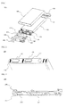
- FIG. 1 is an exploded perspective view typically illustrating a secondary battery pack according to an embodiment of the present invention
- FIG. 2 is a partial perspective view typically illustrating the top of a battery cell of FIG. 1
- FIG. 3 is a perspective view typically illustrating an insulative mounting member mounted to the top of the battery cell of FIG. 1 .
- a secondary battery pack 500 includes s battery cell 100, an insulative mounting member 200, safety elements such as a protection circuit board 310 and a positive temperature coefficient (PTC) element 320, insulative top and bottom caps 400 and 410, and a sheathing film 140.
- safety elements such as a protection circuit board 310 and a positive temperature coefficient (PTC) element 320, insulative top and bottom caps 400 and 410, and a sheathing film 140.
- PTC positive temperature coefficient
- the battery cell 100 is constructed in a structure in which an electrode assembly of a cathode/separator/anode structure is mounted in a prismatic metal container together with an electrolyte in a sealed state.
- Straight type coupling grooves 110 are formed at the top of the battery cell 100 so that the insulative mounting member 200 is coupled to the battery cell 100 through the coupling grooves 110.
- the insulative mounting member 200 has openings, through which electrode terminals 120 and 130 of the battery cell 100 are exposed to the outside. Opposite ends of the insulative mounting member 200 protrude upward by a predetermined height so that the safety elements, such as the protection circuit board 310 and the PTC element 320, can be stably coupled to the top of the insulative mounting member 200.
- the insulative mounting member 200 is mounted to the top of the battery cell 100 in a state in which the insulative mounting member 200 is in direct contact with the top of the battery cell 100.
- straight type coupling protrusions 210 are formed at the bottom of the insulative mounting member 200.
- the insulative top cap 400 is coupled to the top of the battery cell 100 so that the insulative top cap 400 surrounds the insulative mounting member 200 in a state in which the safety elements are coupled to the top of the insulative mounting member 200.
- the insulative top cap 400 extends downward by a predetermined length sufficient to surround the outside of the top of the battery cell 100.
- a warranty label 420 is attached to one side of the top of the insulative top cap 400.
- the insulative bottom cap 410 is attached to the bottom of the battery cell 100 by an adhesive bottom cap tape 411.
- the outer circumference of the battery cell 100 is surrounded by the insulative sheathing film 140.
- FIG. 1 the top of the battery cell of FIG. 1 and the insulative mounting member 200, which will be mounted to the top of the battery cell, will be described in more detail with reference to FIGS. 2 and 3 .
- an anode terminal 120 protrudes from the middle of the top of the battery cell 100, and a battery case constitutes a cathode.
- the anode terminal 120 is electrically insulated from the battery case by an insulative member 121. Consequently, a cathode terminal 130 is formed by attaching a nickel clad member to a predetermined region of the top of the battery cell 100.
- the coupling grooves 110 are formed at the top of the battery cell 100 so that the coupling protrusions 210 ( FIG. 3 ) of the insulative mounting member 200 (see FIG. 1 ) are coupled into the coupling grooves 110.
- the insulative mounting member 200 has a smaller size than the top of the battery cell 100.
- the insulative mounting member 200 is provided at the middle thereof with a first opening 201, through which the anode terminal 120 (see FIG. 2 ) of the battery cell 100 is exposed to the outside.
- a second opening 202 through which a portion (the cathode terminal 130 (see FIG. 2 )) of the top of the battery cell 100 is exposed to the outside, is formed at the insulative mounting member 200 so that the second opening 202 is spaced a predetermined distance from the first opening 201.
- Opposite ends 220 of the insulative mounting member 200 protrude upward by a predetermined height so that the safety elements can be stably coupled to the top of the insulative mounting member 200.
- the coupling protrusions 210 are formed at the bottom of the insulative mounting member 200.
- the coupling protrusions 210 are coupled into the coupling grooves 110 formed at the top of the battery cell 100, thereby achieving the mechanical coupling between the insulative mounting member 200 and the battery cell 100.
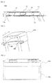
- FIG. 4 is a partial perspective view illustrating the top of a battery cell according to another embodiment of the present invention.
- narrow and long coupling grooves 150 are formed at the top of a battery case 100a generally in the shape of a railroad track so that each of the coupling grooves 150 is spaced a distance w equivalent to 2% of the width W of the top of the battery cell from the outer circumference of the top of the battery case 110a in a state in which the coupling grooves 150 are parallel to the outer circumference of the top of the battery case 110a.
- the coupling grooves 150 are formed at regions of the top of the battery case 110a where the coupling grooves 150 do not interfere with an anode terminal 120, a cathode terminal 130, which is a nickel clad member, and an electrolyte injection port 122 disposed at the top of the battery case 110a.
- FIG. 5 is a partial typical view illustrating a state in which an insulative cap is mounted to the top of the battery cell of FIG. 4, and FIG. 6 is a perspective view typically illustrating a state in which the insulative cap of FIG. 5 is mounted to the top of the battery cell of FIG. 4 .
- coupling grooves 404 are formed at the top of a battery case so that each of the coupling grooves 404 has a depth d equivalent to approximately 50% of the thickness D of the battery case.
- the coupling protrusions 406 of the insulative cap 400a are coupled into the coupling grooves 404 formed at the top of the battery cell 100a so that the insulative cap 400a surrounds the insulative mounting member 200 ( FIG. 1 ) in a state in which safety elements (not shown) are disposed on the insulative mounting member 200, thereby achieving mechanical coupling between the insulative cap 400a and the battery cell 100.
- FIG. 7 is a partial typical view illustrating a state in which an insulative cap is mounted to the top of a battery cell according to a modified embodiment of the present invention.
- each coupling groove 152 formed at the top of a battery case is greater than that of each of the coupling grooves 404 of FIG. 5 .
- FIG. 8 is a partial perspective view typically illustrating the top of a battery cell according to another embodiment of the present invention
- FIG. 9 is a perspective view typically illustrating an insulative mounting member, which will be mounted to the top of the battery cell of FIG. 7 .
- two straight type coupling grooves 164 and a cross type coupling groove 162 are formed at regions of the top of a battery case 110b where the straight type coupling grooves 164 and the cross type coupling groove 162 do not interfere with an anode terminal 120, a cathode terminal 130, which is a nickel clad member, and an electrolyte injection port 122 disposed at the top of the battery case 110b.
- an insulative mounting member 200a is provided at the bottom thereof with two straight type coupling protrusions corresponding to the coupling grooves 164 of FIG. 8 and a cross type coupling protrusions corresponding to the coupling groove 162 of FIG. 8 .
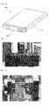
- FIG. 10 is a perspective view typically illustrating a secondary battery pack manufactured according to the embodiment of FIG. 5 .
- a secondary battery pack 500a is configured so that the remaining parts of the secondary battery pack 500a, excluding external input and output terminal parts, are electrically insulated from the outside by the insulative cap 400a, the sheathing film 140, and the bottom cap (not shown), in a state in which the safety elements and the insulative mounting member are mounted to the top of the battery cell.
- the shape, position, and number of the coupling grooves, formed at the top of the battery cell, and the coupling protrusions corresponding to the coupling grooves may be variously changed based on the above description within the scope of the present invention.
- Slurry prepared by mixing lithium cobalt oxide, PVdf and a conducting agent in a generally known composition ratio, was coated on an aluminum current collector to manufacture a cathode.
- a separator cut so as to have a size slightly greater than that of the cathode and the anode was disposed between the cathode and the anode to manufacture an electrode assembly.
- the manufactured electrode assembly was mounted in a prismatic aluminum battery container.
- a battery container cover was mounted to the battery container, and an electrolyte was injected into the battery case through an electrolyte injection port to manufacture a battery cell.
- An insulative mounting member was mounted to the top of the battery cell configured as shown in FIG. 4 , and safety elements were connected to the insulative mounting member. Subsequently, coupling protrusions formed at the bottom of an insulative cap were coupled into coupling grooves formed at the top of the battery case in a state in which a adhesive agent is applied to coupling grooves so that the insulative cap were mounted to the top of the battery cell.
- an insulative bottom cap was coupled to the bottom of the battery cell, and the outer circumference of the battery cell was covered by a sheathing film, to manufacture a secondary battery pack as shown in FIG. 10 .
- a secondary battery pack was manufactured in the same manner as Example 1 except that the insulative cap was coupled to the battery cell by a adhesive agent applied between the battery cell and the insulative cap without forming the coupling grooves and the coupling protrusions at the top of the battery cell and at the bottom of the insulative cap.
- Twist tests were carried out on 20 battery packs manufactured according to Example 1 and 20 battery packs manufactured according to Comparative Example 1 to measure the coupling strength between the battery cell of each of the battery packs and the insulative mounting member coupled to the battery cell (See FIG. 12 ). That is, external force was applied to the insulative bottom cap of each of the battery packs in one direction in a state in which the insulative top cap of each of the battery packs was fixed so that the insulative bottom cap of each of the battery packs was twisted. At this time, the external force was gradually increased to measure the magnitudes of the external force when the separation between the battery cell of each of the battery packs and the insulative cap coupled to the top of the battery cell occurred.
- Table 2 The experiment results are indicated in Table 2 below.
- Example 1 Comparative Example 1 20 or less 0 15 20 to 25 0 5 25 to 30 0 - 30 to 35 0 - 35 to 40 0 - 40 to 45 11 - 45 or more 9 -
- the assembly process of the secondary battery pack according to the present invention is greatly simplified. Also, the coupling strength between the battery cell and the insulative cap is stably maintained.
Abstract
Description
- The present invention relates to a secondary battery pack, and, more particularly, to a secondary battery pack including a battery cell having an electrode assembly of a cathode/separator/anode structure mounted in a battery case together with an electrolyte in a sealed state, an insulative mounting member having openings, through which electrode terminals of the battery cell are exposed to the outside, the insulative mounting member being configured to have a structure in which a safety element is mounted to the top of the insulative mounting member, the insulative mounting member being disposed in direct contact with the top of the battery cell, and an insulative cap coupled to the top of the battery cell so that the insulative cap surrounds the insulative mounting member in a state in which the safety element is mounted to the insulative mounting member, wherein the battery case is provided at the top thereof with a coupling groove, and the insulative cap is provided at the bottom thereof with a coupling protrusion formed in a shape corresponding to the coupling groove, the coupling of the insulative cap to the battery cell being achieved by the insertion of the coupling protrusion into the coupling groove.
- As mobile devices have been increasingly developed, and the demand for such mobile devices has increased, the demand for secondary batteries has also sharply increased. Among such secondary batteries is a lithium secondary battery exhibiting high energy density and operating voltage and excellent preservation and service-life characteristics, which has been widely used as an energy source for various electronic products as well as for the mobile devices.
- However, various combustible materials are contained in the lithium secondary battery. As a result, there is a possibility of danger in that the lithium secondary battery will be heated or explode due to overcharge, overcurrent or any other external physical impacts. In other words, the lithium secondary battery has low safety. Consequently, a protection circuit module (PCM) to effectively control an abnormal state of the lithium secondary battery, such as overcharge, is mounted in the lithium secondary battery in a state in which the PCM is connected to a battery cell of the lithium secondary battery.
- Generally, it is necessary for safety elements, including the PCM, to be maintained in electrical connection with electrode terminals of a battery cell and, at the same time, to be electrically isolated from other parts of the battery cell. Consequently, an insulative mounting member is necessary to achieve such connection, and an adhesive agent is applied between the battery cell and the insulative mounting member to achieve the coupling between the battery cell and the insulative mounting member. However, this coupling method may reduce the coupling strength of a battery pack. An electric short circuit may occur in the battery cell due to reduction of the coupling strength, when external impact is applied to the battery cell, with the result that the battery cell may catch fire or explode. In other words, safety-related problems may occur.
- Also, an insulative cap is coupled to the top of the battery cell so that the insulative cap surrounds the insulative mounting member in a state in which the safety elements are mounted to the insulative mounting member to protect the battery cell against external impact, to increase the mechanical strength of the members mounted to the top of the battery cell and to maintain electrical insulation of the battery cell.
- In this case, the coupling between the insulative cap and the top of the battery cell is generally achieved by bonding. However, this coupling method may also reduce the coupling strength between the battery cell and the insulative cap like the coupling between the battery cell and the insulative mounting member as described above.
- Consequently, there is a high necessity for technology to secure stable coupling strength between the battery cell and the insulative cap.
- Therefore, the present invention has been made to solve the above problems, and other technical problems that have yet to be resolved.
- As the result of a variety of extensive and intensive studies and experiments to solve the problems as described above, the inventors of the present application have found that, when a secondary battery pack is configured by coupling an insulative cap to the top of a battery cell through a specific coupling structure between the insulative cap and the battery cell, an assembly process of the secondary battery pack is greatly simplified and, at the same time, the coupling strength between the battery cell and the insulative cap is stably maintained.
- Therefore, it is an object of the present invention to provide a secondary battery pack wherein an insulative cap is coupled to the top of a battery cell through a specific coupling structure between the battery cell and the insulative cap.
- In accordance with one aspect of the present invention, the above and other objects can be accomplished by the provision of a secondary battery pack including a battery cell having an electrode assembly of a cathode/separator/anode structure mounted in a battery case together with an electrolyte in a sealed state, an insulative mounting member having openings, through which electrode terminals of the battery cell are exposed to the outside, the insulative mounting member being configured to have a structure in which a safety element is mounted to the top of the insulative mounting member, the insulative mounting member being disposed in direct contact with the top of the battery cell, and an insulative cap coupled to the top of the battery cell so that the insulative cap surrounds the insulative mounting member in a state in which the safety element is mounted to the insulative mounting member, wherein the battery case is provided at the top thereof with a coupling groove, and the insulative cap is provided at the bottom thereof with a coupling protrusion formed in a shape corresponding to the coupling groove, the coupling of the insulative cap to the battery cell being achieved by the insertion of the coupling protrusion into the coupling groove.
- As described above, the secondary battery pack according to the present invention includes the battery cell, in which the electrode assembly is mounted, the insulative mounting member, to the top of which the safety element is mounted in a state in which the insulative mounting member is disposed in tight contact with the top of the battery cell, and the insulative cap, which is coupled to the top of the battery cell. The coupling between the top of the battery cell and the insulative cap is achieved by the insertion of the coupling protrusion into the coupling groove corresponding to the coupling protrusion.
- Generally, the coupling of the insulative cap to the battery case is achieved by bonding as previously described. However, this coupling method may reduce the coupling strength of the battery pack. Also, the maintenance of the battery pack is not easy.
- In the secondary battery pack according to the present invention, on the other hand, coupling of the insulative cap to the battery case is achieved by the mechanical coupling between and the coupling grooves of the battery case and the coupling protrusion of the insulative cap. Consequently, a manufacturing process of the battery pack is simplified, thereby reducing manufacturing cost and achieve easy maintenance of the battery pack.
- Also, the contact interface between the narrow and long coupling groove formed at the top of the battery case and the coupling protrusion of the insulative cap is increased, and therefore, the coupling force between the coupling protrusion and the coupling groove is further increased.
- The coupling groove may be formed at the top of the battery case so that the coupling groove is spaced a predetermined distance from the outer circumference of the top of the battery case in a state in which the coupling groove is parallel to the outer circumference of the top of the battery case. For example, the coupling groove may be formed partially or wholly at regions of the top of the battery case excluding a protruding terminal, an electrolyte injection port and a nickel clad member disposed at the top of the battery cell.
- In the above structure, the distance may be, for example, 2 to 10% of the width of the top of the battery cell at a region of the top of the battery cell where the coupling groove does not interfere with the protruding terminal, the electrolyte injection port and the nickel clad member disposed at the top of the battery cell as described above.
- The coupling groove may be formed in a planar narrow and long straight shape or in a planar narrow and long '=' shape. In a case in which the coupling groove is formed in the shape of a railroad track, an example of the '=' shape, the contact interface between the coupling groove and the coupling protrusion is increased as compared with a case in which the coupling groove is formed in a straight shape.
- The structure of the coupling groove is not particularly restricted so long as the coupling groove is formed at the top of the battery case so that the coupling groove has a depth sufficient for the coupling protrusion of the insulative cap to be easily coupled into the coupling groove. For example, the coupling groove may be formed at the top of the battery case so that the coupling groove has a depth equivalent to 10 to 70% of the thickness of the battery case.
- If the depth of the coupling groove is less than 10% of the thickness of the battery case, it is difficult to achieved desired coupling force between the battery case and the insulative cap. If the depth of the coupling groove is more than 70% of the thickness of the battery case, on the other hand, the mechanical strength of the battery case is reduced.
- The coupling protrusion may be formed at the bottom of the insulative cap so that the coupling protrusion has a size corresponding to the depth of the coupling groove for the coupling protrusion to be disposed in tight contact with the bottom of the coupling groove.
- It is required for the battery case to be easily manufactured and to exhibit a mechanical strength greater than a predetermined level. For this reason, the battery case may be a metal container, preferably an aluminum container.
- The insulative mounting member is configured to have a structure in which the safety element is mounted to the top of the insulative mounting member. The insulative mounting member is formed of an insulative material and is disposed in direct contact with the top of the battery cell. In a preferred example, the insulative mounting member may have a smaller size than the top of the battery cell, and the insulative mounting member may be provided with a first opening, through which the first electrode terminal of the battery cell is exposed to the outside, formed at the middle thereof and a second opening, through which a portion (the second electrode terminal) of the top of the battery cell is exposed to the outside, spaced a predetermined distance from the first opening. Also, opposite ends of the insulative mounting member may protrude upward by a predetermined height so that the safety element can be stably coupled to the top of the insulative mounting member.
- That is, since the insulative mounting member has a smaller size than the top of the battery cell, the insulative cap may be easily coupled to the top of the battery cell so that the insulative cap surrounds the insulative mounting member in a state in which the insulative mounting member is mounted to the top of the battery cell.
- The safety element may include a rectangular protection circuit module (PCM) having a protection circuit to control the overcharge, overdischarge and overcurrent of the battery cell and a pair of connecting members electrically connected to the protection circuit, which is mounted to the bottom of the rectangular protection circuit module. For example, the safety element may be one or more selected from a group consisting of a positive temperature coefficient (PTC) element, a fuse and a protection circuit board.
- According to circumstances, the safety element may include the PTC element and the protection circuit board. One end of the PTC element may be connected to the first electrode terminal of the battery cell, the other end of the PTC element may be connected to the protection circuit board, and the second electrode terminal of the battery cell may be connected to the protection circuit board.
- For example, the electrical connection (a) between the PTC element and the protection circuit board and the electrical connection (b) between the second electrode terminal of the battery cell and the protection circuit board may be achieved by variable connecting members. In particular, a connecting member for the electrical connection (a) and a connecting member for the electrical connection (b) may be coupled to the protection circuit board, and then the connecting members may be coupled to the respective electrode terminals of the battery cell.
- The connecting members are not particularly restricted so long as the connecting members are made of a variable conductive material. Preferably, each of the connecting members is formed of a nickel plate.
- The connecting members may be coupled to the electrode terminals of the battery cell, in a state in which the protection circuit board is placed on the top of the battery cell so that the angle between the protection circuit board and the top of the battery cell is approximately 90 degrees or more, and the variable connecting members may be bent so that the protection circuit board is mounted to the insulative mounting member in a state in which the protection circuit board is parallel to the top of the battery cell. Consequently, the connecting members may be coupled to the protection circuit board so that the bent portions of the connecting members are directed to the same side.
- For example, the nickel plates may be coupled to the electrode terminals by spot welding, in a state in which the plate-shaped PCM is located so that the PCM is perpendicular to the top of the battery cell, and the nickel plates may be bent and coupled to each other so that the PCM is mounted to the insulative mounting member in a state in which the PCM is in parallel to the top of the battery cell.
- The coupling between the coupling groove and the coupling protrusion is achieved in the longitudinal direction of the battery cell with the result that the coupling groove and the coupling protrusion may be more easily separated from each other by the longitudinal tensile force than impact applied to the battery cell in the direction perpendicular to the battery cell. For this reason, the coupling protrusion may be inserted into the coupling groove, after an adhesive agent is injected into the coupling groove, to solve the above-mentioned problem.
- According to circumstances, an adhesive agent may be further applied to the top of the battery cell or the bottom of the insulative cap so as to increase the coupling strength between the coupling groove and the coupling protrusion.
- The insulative cap may extend downward by a predetermined length sufficient for at least a portion of the insulative cap to surround the outside of the top of the battery cell in a state in which the insulative cap is mounted to the battery cell.
- For example, the downward extending portion of the insulative cap may be coupled to the outside of the top of the battery cell by bonding or mechanical coupling.
- The secondary battery pack may further include another insulative cap (bottom cap) coupled to the bottom of the battery cell in addition to the insulative cap coupled to the top of the battery cell. Also, the secondary battery pack may further include a sheathing film attached to the outside of the battery case of the battery cell. As a result, it is possible to protect the battery cell against external impact and to maintain the electrical insulation of the battery pack.
- Preferably, the sheathing film is attached to the outside of the battery case of the battery cell so that the sheathing film surrounds the downward extending portion of the insulative cap.
- In the secondary battery pack according to the present invention, any battery cells may be used in various manners irrespective of the kind and shape of the battery cells. A prismatic lithium secondary battery cell is preferably used.
- In accordance with another aspect of the present invention, there is provided a secondary battery pack wherein coupling force between a battery case and an insulative mounting member is increased. Specifically, the secondary battery pack includes a battery cell having an electrode assembly of a cathode/separator/anode structure mounted in a battery case together with an electrolyte in a sealed state, an insulative mounting member having openings, through which electrode terminals of the battery cell are exposed to the outside, the insulative mounting member being configured to have a structure in which a safety element is mounted to the top of the insulative mounting member, the insulative mounting member being disposed in direct contact with the top of the battery cell, and an insulative cap coupled to the top of the battery cell so that the insulative cap surrounds the insulative mounting member in a state in which the safety element is mounted to the insulative mounting member, wherein the battery case is provided at the top thereof with at least one coupling groove, and the insulative mounting member is provided at the bottom thereof with at least one coupling protrusion formed in a shape corresponding to the at least one coupling groove, the coupling of the insulative mounting member to the battery cell being achieved by the insertion of the at least one coupling protrusion into the at least one coupling groove.
- The contact interface between the coupling groove formed at the top of the battery case and the coupling protrusion formed at the insulative mounting member is increased, and therefore, the coupling force between the coupling groove and the coupling protrusion is further increased.
- The structure of the coupling groove is not particularly restricted so long as the coupling force between the coupling protrusion of the insulative mounting member and the coupling groove is increased. For example, the coupling groove may be formed in a planar straight shape, in a planar cross shape or in a planar oval shape in which the contact interface between the coupling groove and the coupling protrusion is further increased.
- In this case, the coupling groove may be formed at the top of the electrode terminal upwardly exposed from the top of the battery case. Specifically, the coupling groove may be formed a region of the top of the battery case where the coupling groove does not interfere with a protruding terminal, an electrolyte injection port and a nickel clad member disposed at the top of the battery case.
- According to circumstances, both the coupling groove for coupling of the insulative cap to the battery case and the coupling groove for coupling of the insulative mounting member to the battery case may be formed at the top of the battery case.
- The above and other objects, features and other advantages of the present invention will be more clearly understood from the following detailed description taken in conjunction with the accompanying drawings, in which:
-
FIG. 1 is an exploded perspective view illustrating a secondary battery pack according to an embodiment of the present invention; -
FIG. 2 is a partial perspective view illustrating the top of a battery cell ofFIG. 1 ; -
FIG. 3 is a perspective view illustrating an insulative mounting member, which will be mounted to the top of the battery cell ofFIG. 1 ; -
FIG. 4 is a partial perspective view illustrating the top of a battery cell according to another embodiment of the present invention; -
FIG. 5 is a partial typical view illustrating a state in which an insulative cap is mounted to the top of the battery cell ofFIG. 4 ; -
FIG. 6 is a perspective view illustrating a state in which the insulative cap ofFIG. 5 is mounted to the top of the battery cell ofFIG. 4 ; -
FIG. 7 is a partial typical view illustrating a state in which an insulative cap is mounted to the top of a battery cell according to a modified embodiment of the present invention; -
FIG. 8 is a partial perspective view illustrating the top of a battery cell according to another embodiment of the present invention; -
FIG. 9 is a perspective view illustrating an insulative mounting member, which will be mounted to the top of the battery cell ofFIG. 7 ; -
FIG. 10 is a perspective view illustrating a secondary battery pack manufactured according to the embodiment ofFIG. 5 ; -
FIG. 11 is a photograph illustrating an experimental process performed according to Experimental Example 1 of the present invention; and -
FIG. 12 is a photograph illustrating an experimental process performed according to Experimental Example 2 of the present invention. - Now, preferred embodiments of the present invention will be described in detail with reference to the accompanying drawings. It should be noted, however, that the scope of the present invention is not limited by the illustrated embodiments.
-
FIG. 1 is an exploded perspective view typically illustrating a secondary battery pack according to an embodiment of the present invention,FIG. 2 is a partial perspective view typically illustrating the top of a battery cell ofFIG. 1, and FIG. 3 is a perspective view typically illustrating an insulative mounting member mounted to the top of the battery cell ofFIG. 1 . - Referring to these drawings, a
secondary battery pack 500 includes sbattery cell 100, aninsulative mounting member 200, safety elements such as aprotection circuit board 310 and a positive temperature coefficient (PTC)element 320, insulative top andbottom caps sheathing film 140. - The
battery cell 100 is constructed in a structure in which an electrode assembly of a cathode/separator/anode structure is mounted in a prismatic metal container together with an electrolyte in a sealed state. Straighttype coupling grooves 110 are formed at the top of thebattery cell 100 so that theinsulative mounting member 200 is coupled to thebattery cell 100 through thecoupling grooves 110. - The
insulative mounting member 200 has openings, through whichelectrode terminals battery cell 100 are exposed to the outside. Opposite ends of theinsulative mounting member 200 protrude upward by a predetermined height so that the safety elements, such as theprotection circuit board 310 and thePTC element 320, can be stably coupled to the top of theinsulative mounting member 200. Theinsulative mounting member 200 is mounted to the top of thebattery cell 100 in a state in which theinsulative mounting member 200 is in direct contact with the top of thebattery cell 100. Also, straighttype coupling protrusions 210, corresponding to the coupling grooves formed at the top of thebattery cell 100, are formed at the bottom of theinsulative mounting member 200. - The insulative
top cap 400 is coupled to the top of thebattery cell 100 so that the insulativetop cap 400 surrounds theinsulative mounting member 200 in a state in which the safety elements are coupled to the top of theinsulative mounting member 200. The insulativetop cap 400 extends downward by a predetermined length sufficient to surround the outside of the top of thebattery cell 100. Awarranty label 420 is attached to one side of the top of the insulativetop cap 400. - The
insulative bottom cap 410 is attached to the bottom of thebattery cell 100 by an adhesivebottom cap tape 411. The outer circumference of thebattery cell 100 is surrounded by theinsulative sheathing film 140. - Hereinafter, the top of the battery cell of
FIG. 1 and theinsulative mounting member 200, which will be mounted to the top of the battery cell, will be described in more detail with reference toFIGS. 2 and 3 . - Referring to
FIG. 2 , ananode terminal 120 protrudes from the middle of the top of thebattery cell 100, and a battery case constitutes a cathode. Theanode terminal 120 is electrically insulated from the battery case by aninsulative member 121. Consequently, acathode terminal 130 is formed by attaching a nickel clad member to a predetermined region of the top of thebattery cell 100. Thecoupling grooves 110 are formed at the top of thebattery cell 100 so that the coupling protrusions 210 (FIG. 3 ) of the insulative mounting member 200 (seeFIG. 1 ) are coupled into thecoupling grooves 110. - Referring to
FIG. 3 , theinsulative mounting member 200 has a smaller size than the top of thebattery cell 100. Theinsulative mounting member 200 is provided at the middle thereof with afirst opening 201, through which the anode terminal 120 (seeFIG. 2 ) of thebattery cell 100 is exposed to the outside. Also, asecond opening 202, through which a portion (the cathode terminal 130 (seeFIG. 2 )) of the top of thebattery cell 100 is exposed to the outside, is formed at theinsulative mounting member 200 so that thesecond opening 202 is spaced a predetermined distance from thefirst opening 201. Opposite ends 220 of theinsulative mounting member 200 protrude upward by a predetermined height so that the safety elements can be stably coupled to the top of theinsulative mounting member 200. - Also, the
coupling protrusions 210, corresponding to the coupling grooves 110 (FIG. 2 ) formed at the top of thebattery cell 100, are formed at the bottom of theinsulative mounting member 200. The coupling protrusions 210 are coupled into thecoupling grooves 110 formed at the top of thebattery cell 100, thereby achieving the mechanical coupling between theinsulative mounting member 200 and thebattery cell 100. -
FIG. 4 is a partial perspective view illustrating the top of a battery cell according to another embodiment of the present invention. - Referring to
FIG. 4 , narrow andlong coupling grooves 150 are formed at the top of abattery case 100a generally in the shape of a railroad track so that each of thecoupling grooves 150 is spaced a distance w equivalent to 2% of the width W of the top of the battery cell from the outer circumference of the top of thebattery case 110a in a state in which thecoupling grooves 150 are parallel to the outer circumference of the top of thebattery case 110a. - Also, the
coupling grooves 150 are formed at regions of the top of thebattery case 110a where thecoupling grooves 150 do not interfere with ananode terminal 120, acathode terminal 130, which is a nickel clad member, and anelectrolyte injection port 122 disposed at the top of thebattery case 110a. -
FIG. 5 is a partial typical view illustrating a state in which an insulative cap is mounted to the top of the battery cell ofFIG. 4, and FIG. 6 is a perspective view typically illustrating a state in which the insulative cap ofFIG. 5 is mounted to the top of the battery cell ofFIG. 4 . - Referring to
FIG. 5 , aninsulative cap 400a is provided at the bottom thereof withcoupling protrusions 406, formed in a shape corresponding to thecoupling grooves 150 ofFIG. 4 , i.e. in a '=' shape, extending in the longitudinal direction L of the top of the battery cell. - Also,
coupling grooves 404 are formed at the top of a battery case so that each of thecoupling grooves 404 has a depth d equivalent to approximately 50% of the thickness D of the battery case. - Referring to
FIG. 6 together withFIG. 5 , thecoupling protrusions 406 of theinsulative cap 400a are coupled into thecoupling grooves 404 formed at the top of thebattery cell 100a so that theinsulative cap 400a surrounds the insulative mounting member 200 (FIG. 1 ) in a state in which safety elements (not shown) are disposed on theinsulative mounting member 200, thereby achieving mechanical coupling between theinsulative cap 400a and thebattery cell 100. -
FIG. 7 is a partial typical view illustrating a state in which an insulative cap is mounted to the top of a battery cell according to a modified embodiment of the present invention. - Referring to
FIG. 7 together withFIG. 5 , the width of eachcoupling groove 152 formed at the top of a battery case is greater than that of each of thecoupling grooves 404 ofFIG. 5 . -
FIG. 8 is a partial perspective view typically illustrating the top of a battery cell according to another embodiment of the present invention, andFIG. 9 is a perspective view typically illustrating an insulative mounting member, which will be mounted to the top of the battery cell ofFIG. 7 . - Referring first to
FIG. 8 , two straighttype coupling grooves 164 and a crosstype coupling groove 162 are formed at regions of the top of abattery case 110b where the straighttype coupling grooves 164 and the crosstype coupling groove 162 do not interfere with ananode terminal 120, acathode terminal 130, which is a nickel clad member, and anelectrolyte injection port 122 disposed at the top of thebattery case 110b. - Referring now to
FIG. 9 , aninsulative mounting member 200a is provided at the bottom thereof with two straight type coupling protrusions corresponding to thecoupling grooves 164 ofFIG. 8 and a cross type coupling protrusions corresponding to thecoupling groove 162 ofFIG. 8 . -
FIG. 10 is a perspective view typically illustrating a secondary battery pack manufactured according to the embodiment ofFIG. 5 . - Referring to
FIG. 10 , asecondary battery pack 500a is configured so that the remaining parts of thesecondary battery pack 500a, excluding external input and output terminal parts, are electrically insulated from the outside by theinsulative cap 400a, thesheathing film 140, and the bottom cap (not shown), in a state in which the safety elements and the insulative mounting member are mounted to the top of the battery cell. - The shape, position, and number of the coupling grooves, formed at the top of the battery cell, and the coupling protrusions corresponding to the coupling grooves may be variously changed based on the above description within the scope of the present invention.
- Hereinafter, an example of the present invention will be described in more detail. It should be noted, however, that the scope of the present invention is not limited by the illustrated example.
- Slurry, prepared by mixing lithium cobalt oxide, PVdf and a conducting agent in a generally known composition ratio, was coated on an aluminum current collector to manufacture a cathode. Slurry, prepared by mixing graphite, PVdf and a conducting agent in a generally known composition ratio, was coated on a copper current collector to manufacture an anode.
- A separator cut so as to have a size slightly greater than that of the cathode and the anode was disposed between the cathode and the anode to manufacture an electrode assembly. The manufactured electrode assembly was mounted in a prismatic aluminum battery container. A battery container cover was mounted to the battery container, and an electrolyte was injected into the battery case through an electrolyte injection port to manufacture a battery cell.
- An insulative mounting member was mounted to the top of the battery cell configured as shown in
FIG. 4 , and safety elements were connected to the insulative mounting member. Subsequently, coupling protrusions formed at the bottom of an insulative cap were coupled into coupling grooves formed at the top of the battery case in a state in which a adhesive agent is applied to coupling grooves so that the insulative cap were mounted to the top of the battery cell. - Subsequently, an insulative bottom cap was coupled to the bottom of the battery cell, and the outer circumference of the battery cell was covered by a sheathing film, to manufacture a secondary battery pack as shown in
FIG. 10 . - A secondary battery pack was manufactured in the same manner as Example 1 except that the insulative cap was coupled to the battery cell by a adhesive agent applied between the battery cell and the insulative cap without forming the coupling grooves and the coupling protrusions at the top of the battery cell and at the bottom of the insulative cap.
- Bending tests were carried out on 20 battery packs manufactured according to Example 1 and 20 battery packs manufactured according to Comparative Example 1 to measure the coupling strength between the battery cell of each of the battery packs and the insulative cap coupled to the battery cell (See
FIG. 11 ). That is, load applied to the middle of each of the battery packs was gradually increased in a state in which the insulative top cap and the insulative bottom cap of each of the battery packs were fixed to measure the magnitudes of the load when the battery packs broke. The experiment results are indicated in Table 1 below.<TABLE 1> Breaking load (kgf) Example 1 Comparative Example 1 25 or less 0 6 25 to 30 0 12 30 to 35 0 2 45 to 50 0 - 50 to 55 12 - 55 or more 8 - - As can be seen from Table 1 above, the coupling force of the battery packs manufactured according to the example of the present invention was greatly increased as compared with the coupling force of the battery packs manufactured according to Comparative Example 1.
- That is, when a load of 35 kgf or less was applied to the battery packs manufactured according to Comparative Example 1, the battery packs broke. Most of the battery packs broke even when a load of less than 30 kgf was applied to the battery packs. On the contrary, only when a load of 50 kgf or more was applied to the battery packs manufactured according to Example 1, the battery packs broke. Some of the battery packs withstood even a load of 55 kgf. This is because, for the battery packs manufactured according to Comparative Example 1, the separation between the battery cells and the corresponding insulative caps occurred when impact having a magnitude exceeding the adhesive force of the adhesive agent used to couple the battery cells and the corresponding insulative caps was applied to the battery packs, whereas, for the battery packs manufactured according to Example 1, the coupling force between the battery cells and the corresponding insulative caps was greatly increased by the mechanical coupling between the coupling protrusions and the corresponding coupling grooves even when only a relatively small amount of an adhesive agent was used or an adhesive agent was not used.
- Twist tests were carried out on 20 battery packs manufactured according to Example 1 and 20 battery packs manufactured according to Comparative Example 1 to measure the coupling strength between the battery cell of each of the battery packs and the insulative mounting member coupled to the battery cell (See
FIG. 12 ). That is, external force was applied to the insulative bottom cap of each of the battery packs in one direction in a state in which the insulative top cap of each of the battery packs was fixed so that the insulative bottom cap of each of the battery packs was twisted. At this time, the external force was gradually increased to measure the magnitudes of the external force when the separation between the battery cell of each of the battery packs and the insulative cap coupled to the top of the battery cell occurred. The experiment results are indicated in Table 2 below.<TABLE 2> Breaking torque (kg.cm) Example 1 Comparative Example 1 20 or less 0 15 20 to 25 0 5 25 to 30 0 - 30 to 35 0 - 35 to 40 0 - 40 to 45 11 - 45 or more 9 - - As can be seen from Table 2 above, the coupling force of the battery packs manufactured according to the example of the present invention was greatly increased as compared with the coupling force of the battery packs manufactured according to Comparative Example 1.
- That is, when an external force of 25 kg.cm or less was applied to the battery packs manufactured according to Comparative Example 1, the battery packs broke. On the contrary, only when an external force of 40 kg.cm or more was applied to the battery packs manufactured according to Example 1, the battery packs broke. This is because, for the battery packs manufactured according to Comparative Example 1, the coupling between the battery cells and the corresponding insulative caps was accomplished by only the adhesive agent, whereas, for the battery packs manufactured according to Example 1, the coupling between the battery cells and the corresponding insulative caps was accomplished by the mechanical coupling between the coupling protrusions and the corresponding coupling grooves. Especially, the coupling force of the battery packs manufactured according to Example 1 was greatly increased when twisting force was applied to the battery packs.
- As is apparent from the above description, the assembly process of the secondary battery pack according to the present invention is greatly simplified. Also, the coupling strength between the battery cell and the insulative cap is stably maintained.
- Although the preferred embodiments of the present invention have been disclosed for illustrative purposes, those skilled in the an will appreciate that various modifications, additions and substitutions are possible, without departing from the scope and spirit of the invention as disclosed in the accompanying claims.
Claims (19)
- A secondary battery pack comprising:a battery cell having an electrode assembly of a cathode/separator/anode structure mounted in a battery case together with an electrolyte in a sealed state;an insulative mounting member having openings, through which electrode terminals of the battery cell are exposed to the outside, the insulative mounting member being configured to have a structure in which a safety element is mounted to the top of the insulative mounting member, the insulative mounting member being disposed in direct contact with the top of the battery cell; andan insulative cap coupled to the top of the battery cell so that the insulative cap surrounds the insulative mounting member in a state in which the safety element is mounted to the insulative mounting member, whereinthe battery case is provided at the top thereof with a coupling groove, and the insulative cap is provided at the bottom thereof with a coupling protrusion formed in a shape corresponding to the coupling groove, the coupling of the insulative cap to the battery cell being achieved by the insertion of the coupling protrusion into the coupling groove.
- The secondary battery pack according to claim 1, wherein the coupling groove is formed at the top of the battery case so that the coupling groove is spaced a predetermined distance from the outer circumference of the top of the battery case in a state in which the coupling groove is parallel to the outer circumference of the top of the battery case.
- The secondary battery pack according to claim 2, wherein the distance is 2 to 10% of the width of the top of the battery cell.
- The secondary battery pack according to claim 1, wherein the coupling groove is formed in a planar narrow and long straight shape or in a planar narrow and long '=' shape.
- The secondary battery pack according to claim 1, wherein the coupling groove is formed at the top of the battery case so that the coupling groove has a depth equivalent to 2 to 50% of the thickness of the battery case.
- The secondary battery pack according to claim 1, wherein the coupling protrusion is formed at the bottom of the insulative cap so that the coupling protrusion has a size corresponding to the depth of the coupling groove.
- The secondary battery pack according to claim 1, wherein the battery case is a metal container.
- The secondary battery pack according to claim 1, wherein the insulative mounting member has a smaller size than the top of the battery cell, and the insulative mounting member is provided with a first opening, through which the first electrode terminal of the battery cell is exposed to the outside, formed at the middle thereof and a second opening, through which a portion (the second electrode terminal) of the top of the battery cell is exposed to the outside, spaced a predetermined distance from the first opening.
- The secondary battery pack according to claim 8, wherein opposite ends of the insulative mounting member protrude upward by a predetermined height.
- The secondary battery pack according to claim 1, wherein the safety element is one or more selected from a group consisting of a positive temperature coefficient (PTC) element, a fuse and a protection circuit board.
- The secondary battery pack according to claim 1 or 10, wherein the safety element comprises a PTC element and a protection circuit board, one end of the PTC element is connected to the first electrode terminal of the battery cell, the other end of the PTC element is connected to the protection circuit board, and the second electrode terminal of the battery cell is connected to the protection circuit board.
- The secondary battery pack according to claim 1, wherein an adhesive agent is injected into the coupling groove before the coupling protrusion is inserted into the coupling groove.
- The secondary battery pack according to claim 1, wherein the insulative cap extends downward by a predetermined length sufficient for at least a portion of the insulative cap to surround the outside of the top of the battery cell in a state in which the insulative cap is mounted to the battery cell.
- The secondary battery pack according to claim 1, further comprising a sheathing film attached to the outside of the battery case.
- The secondary battery pack according to claim 14, wherein the sheathing film is attached to the outside of the battery case so that the sheathing film surrounds the downward extending portion of the insulative cap.
- The secondary battery pack according to claim 1, wherein the battery cell is a prismatic lithium secondary battery cell.
- A secondary battery pack comprising:a battery cell having an electrode assembly of a cathode/separator/anode structure mounted in a battery case together with an electrolyte in a sealed state;an insulative mounting member having openings, through which electrode terminals of the battery cell are exposed to the outside, the insulative mounting member being configured to have a structure in which a safety element is mounted to the top of the insulative mounting member, the insulative mounting member being disposed in direct contact with the top of the battery cell; andan insulative cap coupled to the top of the battery cell so that the insulative cap surrounds the insulative mounting member in a state in which the safety element is mounted to the insulative mounting member, whereinthe battery case is provided at the top thereof with at least one coupling groove, and the insulative mounting member is provided at the bottom thereof with at least one coupling protrusion formed in a shape corresponding to the at least one coupling groove, the coupling of the insulative mounting member to the battery cell being achieved by the insertion of the at least one coupling protrusion into the at least one coupling groove.
- The secondary battery pack according to claim 17, wherein the coupling groove is formed in a planar straight shape, in a planar cross shape or in a planar oval shape.
- The secondary battery pack according to claim 18, wherein the coupling groove is formed at the top of the electrode terminal upwardly exposed from the top of the battery case.
Applications Claiming Priority (2)
| Application Number | Priority Date | Filing Date | Title |
|---|---|---|---|
| KR1020080100647A KR101082860B1 (en) | 2008-10-14 | 2008-10-14 | Secondary Battery Pack |
| PCT/KR2009/005868 WO2010044587A2 (en) | 2008-10-14 | 2009-10-13 | Secondary battery pack |
Publications (3)
| Publication Number | Publication Date |
|---|---|
| EP2337109A2 true EP2337109A2 (en) | 2011-06-22 |
| EP2337109A4 EP2337109A4 (en) | 2014-01-01 |
| EP2337109B1 EP2337109B1 (en) | 2017-08-16 |
Family
ID=42107038
Family Applications (1)
| Application Number | Title | Priority Date | Filing Date |
|---|---|---|---|
| EP09820737.6A Active EP2337109B1 (en) | 2008-10-14 | 2009-10-13 | Secondary battery pack |
Country Status (5)
| Country | Link |
|---|---|
| US (1) | US8852766B2 (en) |
| EP (1) | EP2337109B1 (en) |
| KR (1) | KR101082860B1 (en) |
| CN (1) | CN102171854A (en) |
| WO (1) | WO2010044587A2 (en) |
Cited By (2)
| Publication number | Priority date | Publication date | Assignee | Title |
|---|---|---|---|---|
| BE1025535B1 (en) * | 2017-01-13 | 2019-04-08 | Symbol Technologies Llc | EXCHANGEABLE CONNECTIONABLE CHARGING STATION, BATTERY PACKAGE AND MOBILE DEVICE |
| EP2575193B1 (en) * | 2011-09-29 | 2022-10-26 | GS Yuasa International Ltd. | Battery pack |
Families Citing this family (4)
| Publication number | Priority date | Publication date | Assignee | Title |
|---|---|---|---|---|
| KR101381680B1 (en) * | 2011-10-31 | 2014-04-04 | 주식회사 엘지화학 | Battery Pack Comprising Charging Coil |
| KR101908452B1 (en) * | 2012-06-28 | 2018-10-17 | 에스케이이노베이션 주식회사 | Easy assembling all-in-one secondary battery module |
| KR20140131222A (en) * | 2013-05-03 | 2014-11-12 | 삼성에스디아이 주식회사 | Battery pack |
| CN105896479B (en) * | 2016-05-26 | 2018-10-30 | 深圳先进储能材料国家工程研究中心有限公司 | A kind of built-in constant pressure protection structure member and use its rechargeable battery |
Citations (2)
| Publication number | Priority date | Publication date | Assignee | Title |
|---|---|---|---|---|
| WO2008050956A1 (en) * | 2006-10-23 | 2008-05-02 | Lg Chem, Ltd. | Secondary battery pack |
| WO2008066287A1 (en) * | 2006-11-27 | 2008-06-05 | Lg Chem, Ltd. | Battery pack of excellent productability and structural stability |
Family Cites Families (4)
| Publication number | Priority date | Publication date | Assignee | Title |
|---|---|---|---|---|
| WO2006046343A1 (en) * | 2004-10-27 | 2006-05-04 | Matsushita Electric Industrial Co., Ltd. | Battery pack |
| KR100930473B1 (en) * | 2006-02-13 | 2009-12-09 | 주식회사 엘지화학 | Battery-free battery pack using interference fit rivets |
| KR20080034723A (en) * | 2006-10-17 | 2008-04-22 | 삼성에스디아이 주식회사 | Rechargeable battery |
| KR100875430B1 (en) * | 2007-01-19 | 2008-12-22 | 삼성에스디아이 주식회사 | Secondary battery case and battery pack including same |
-
2008
- 2008-10-14 KR KR1020080100647A patent/KR101082860B1/en active IP Right Grant
-
2009
- 2009-10-13 US US13/122,302 patent/US8852766B2/en active Active
- 2009-10-13 EP EP09820737.6A patent/EP2337109B1/en active Active
- 2009-10-13 CN CN2009801397063A patent/CN102171854A/en active Pending
- 2009-10-13 WO PCT/KR2009/005868 patent/WO2010044587A2/en active Application Filing
Patent Citations (2)
| Publication number | Priority date | Publication date | Assignee | Title |
|---|---|---|---|---|
| WO2008050956A1 (en) * | 2006-10-23 | 2008-05-02 | Lg Chem, Ltd. | Secondary battery pack |
| WO2008066287A1 (en) * | 2006-11-27 | 2008-06-05 | Lg Chem, Ltd. | Battery pack of excellent productability and structural stability |
Non-Patent Citations (1)
| Title |
|---|
| See also references of WO2010044587A2 * |
Cited By (3)
| Publication number | Priority date | Publication date | Assignee | Title |
|---|---|---|---|---|
| EP2575193B1 (en) * | 2011-09-29 | 2022-10-26 | GS Yuasa International Ltd. | Battery pack |
| BE1025535B1 (en) * | 2017-01-13 | 2019-04-08 | Symbol Technologies Llc | EXCHANGEABLE CONNECTIONABLE CHARGING STATION, BATTERY PACKAGE AND MOBILE DEVICE |
| US11271414B2 (en) | 2017-01-13 | 2022-03-08 | Symbol Technologies, Llc | Interchangeably connectable charging cradle, battery pack and mobile device |
Also Published As
| Publication number | Publication date |
|---|---|
| KR101082860B1 (en) | 2011-11-11 |
| WO2010044587A2 (en) | 2010-04-22 |
| EP2337109B1 (en) | 2017-08-16 |
| WO2010044587A3 (en) | 2010-07-01 |
| EP2337109A4 (en) | 2014-01-01 |
| US8852766B2 (en) | 2014-10-07 |
| CN102171854A (en) | 2011-08-31 |
| KR20100041458A (en) | 2010-04-22 |
| US20110262778A1 (en) | 2011-10-27 |
Similar Documents
| Publication | Publication Date | Title |
|---|---|---|
| EP2076930B1 (en) | Secondary battery pack | |
| US8703309B2 (en) | Battery pack of excellent productability and structural stability | |
| US8137837B2 (en) | Secondary battery pack having excellent production process property and structural stability | |
| US7550227B2 (en) | Secondary battery | |
| US8975867B2 (en) | Secondary battery pack of novel structure | |
| KR101059756B1 (en) | New rechargeable battery pack | |
| US9196931B2 (en) | Secondary battery pack having PCM assembly and insulating mounting member of novel structure | |
| US9123951B2 (en) | Secondary battery pack having excellent energy density and PCM assembly therefor | |
| EP2403035B1 (en) | Rechargeable battery pack having a novel structure | |
| EP1878071A1 (en) | Improved middle or large-sized battery pack of increased safety | |
| EP2624336B1 (en) | Secondary battery pack having a novel structure | |
| EP2337109B1 (en) | Secondary battery pack | |
| KR100888283B1 (en) | Secondary Battery Pack Having Excellent Structural Stability | |
| KR100490634B1 (en) | Secondary battery |
Legal Events
| Date | Code | Title | Description |
|---|---|---|---|
| PUAI | Public reference made under article 153(3) epc to a published international application that has entered the european phase |
Free format text: ORIGINAL CODE: 0009012 |
|
| 17P | Request for examination filed |
Effective date: 20110401 |
|
| AK | Designated contracting states |
Kind code of ref document: A2 Designated state(s): AT BE BG CH CY CZ DE DK EE ES FI FR GB GR HR HU IE IS IT LI LT LU LV MC MK MT NL NO PL PT RO SE SI SK SM TR |
|
| AX | Request for extension of the european patent |
Extension state: AL BA RS |
|
| DAX | Request for extension of the european patent (deleted) | ||
| A4 | Supplementary search report drawn up and despatched |
Effective date: 20131203 |
|
| RIC1 | Information provided on ipc code assigned before grant |
Ipc: H01M 10/052 20100101ALI20131127BHEP Ipc: H01M 10/42 20060101ALI20131127BHEP Ipc: H01M 2/04 20060101AFI20131127BHEP Ipc: H01M 2/10 20060101ALI20131127BHEP |
|
| GRAP | Despatch of communication of intention to grant a patent |
Free format text: ORIGINAL CODE: EPIDOSNIGR1 |
|
| INTG | Intention to grant announced |
Effective date: 20170315 |
|
| GRAS | Grant fee paid |
Free format text: ORIGINAL CODE: EPIDOSNIGR3 |
|
| GRAJ | Information related to disapproval of communication of intention to grant by the applicant or resumption of examination proceedings by the epo deleted |
Free format text: ORIGINAL CODE: EPIDOSDIGR1 |
|
| GRAL | Information related to payment of fee for publishing/printing deleted |
Free format text: ORIGINAL CODE: EPIDOSDIGR3 |
|
| GRAR | Information related to intention to grant a patent recorded |
Free format text: ORIGINAL CODE: EPIDOSNIGR71 |
|
| GRAA | (expected) grant |
Free format text: ORIGINAL CODE: 0009210 |
|
| INTC | Intention to grant announced (deleted) | ||
| AK | Designated contracting states |
Kind code of ref document: B1 Designated state(s): AT BE BG CH CY CZ DE DK EE ES FI FR GB GR HR HU IE IS IT LI LT LU LV MC MK MT NL NO PL PT RO SE SI SK SM TR |
|
| INTG | Intention to grant announced |
Effective date: 20170711 |
|
| REG | Reference to a national code |
Ref country code: GB Ref legal event code: FG4D |
|
| REG | Reference to a national code |
Ref country code: CH Ref legal event code: EP |
|
| REG | Reference to a national code |
Ref country code: IE Ref legal event code: FG4D |
|
| REG | Reference to a national code |
Ref country code: AT Ref legal event code: REF Ref document number: 919877 Country of ref document: AT Kind code of ref document: T Effective date: 20170915 |
|
| REG | Reference to a national code |
Ref country code: FR Ref legal event code: PLFP Year of fee payment: 9 |
|
| REG | Reference to a national code |
Ref country code: DE Ref legal event code: R096 Ref document number: 602009047808 Country of ref document: DE |
|
| REG | Reference to a national code |
Ref country code: NL Ref legal event code: MP Effective date: 20170816 |
|
| REG | Reference to a national code |
Ref country code: LT Ref legal event code: MG4D |
|
| REG | Reference to a national code |
Ref country code: AT Ref legal event code: MK05 Ref document number: 919877 Country of ref document: AT Kind code of ref document: T Effective date: 20170816 |
|
| PG25 | Lapsed in a contracting state [announced via postgrant information from national office to epo] |
Ref country code: SE Free format text: LAPSE BECAUSE OF FAILURE TO SUBMIT A TRANSLATION OF THE DESCRIPTION OR TO PAY THE FEE WITHIN THE PRESCRIBED TIME-LIMIT Effective date: 20170816 Ref country code: LT Free format text: LAPSE BECAUSE OF FAILURE TO SUBMIT A TRANSLATION OF THE DESCRIPTION OR TO PAY THE FEE WITHIN THE PRESCRIBED TIME-LIMIT Effective date: 20170816 Ref country code: NO Free format text: LAPSE BECAUSE OF FAILURE TO SUBMIT A TRANSLATION OF THE DESCRIPTION OR TO PAY THE FEE WITHIN THE PRESCRIBED TIME-LIMIT Effective date: 20171116 Ref country code: NL Free format text: LAPSE BECAUSE OF FAILURE TO SUBMIT A TRANSLATION OF THE DESCRIPTION OR TO PAY THE FEE WITHIN THE PRESCRIBED TIME-LIMIT Effective date: 20170816 Ref country code: FI Free format text: LAPSE BECAUSE OF FAILURE TO SUBMIT A TRANSLATION OF THE DESCRIPTION OR TO PAY THE FEE WITHIN THE PRESCRIBED TIME-LIMIT Effective date: 20170816 Ref country code: AT Free format text: LAPSE BECAUSE OF FAILURE TO SUBMIT A TRANSLATION OF THE DESCRIPTION OR TO PAY THE FEE WITHIN THE PRESCRIBED TIME-LIMIT Effective date: 20170816 |
|
| PG25 | Lapsed in a contracting state [announced via postgrant information from national office to epo] |
Ref country code: ES Free format text: LAPSE BECAUSE OF FAILURE TO SUBMIT A TRANSLATION OF THE DESCRIPTION OR TO PAY THE FEE WITHIN THE PRESCRIBED TIME-LIMIT Effective date: 20170816 Ref country code: LV Free format text: LAPSE BECAUSE OF FAILURE TO SUBMIT A TRANSLATION OF THE DESCRIPTION OR TO PAY THE FEE WITHIN THE PRESCRIBED TIME-LIMIT Effective date: 20170816 Ref country code: GR Free format text: LAPSE BECAUSE OF FAILURE TO SUBMIT A TRANSLATION OF THE DESCRIPTION OR TO PAY THE FEE WITHIN THE PRESCRIBED TIME-LIMIT Effective date: 20171117 Ref country code: BG Free format text: LAPSE BECAUSE OF FAILURE TO SUBMIT A TRANSLATION OF THE DESCRIPTION OR TO PAY THE FEE WITHIN THE PRESCRIBED TIME-LIMIT Effective date: 20171116 Ref country code: PL Free format text: LAPSE BECAUSE OF FAILURE TO SUBMIT A TRANSLATION OF THE DESCRIPTION OR TO PAY THE FEE WITHIN THE PRESCRIBED TIME-LIMIT Effective date: 20170816 Ref country code: IS Free format text: LAPSE BECAUSE OF FAILURE TO SUBMIT A TRANSLATION OF THE DESCRIPTION OR TO PAY THE FEE WITHIN THE PRESCRIBED TIME-LIMIT Effective date: 20171216 |
|
| PG25 | Lapsed in a contracting state [announced via postgrant information from national office to epo] |
Ref country code: DK Free format text: LAPSE BECAUSE OF FAILURE TO SUBMIT A TRANSLATION OF THE DESCRIPTION OR TO PAY THE FEE WITHIN THE PRESCRIBED TIME-LIMIT Effective date: 20170816 Ref country code: CZ Free format text: LAPSE BECAUSE OF FAILURE TO SUBMIT A TRANSLATION OF THE DESCRIPTION OR TO PAY THE FEE WITHIN THE PRESCRIBED TIME-LIMIT Effective date: 20170816 Ref country code: RO Free format text: LAPSE BECAUSE OF FAILURE TO SUBMIT A TRANSLATION OF THE DESCRIPTION OR TO PAY THE FEE WITHIN THE PRESCRIBED TIME-LIMIT Effective date: 20170816 |
|
| REG | Reference to a national code |
Ref country code: DE Ref legal event code: R097 Ref document number: 602009047808 Country of ref document: DE |
|
| PG25 | Lapsed in a contracting state [announced via postgrant information from national office to epo] |
Ref country code: IT Free format text: LAPSE BECAUSE OF FAILURE TO SUBMIT A TRANSLATION OF THE DESCRIPTION OR TO PAY THE FEE WITHIN THE PRESCRIBED TIME-LIMIT Effective date: 20170816 Ref country code: MC Free format text: LAPSE BECAUSE OF FAILURE TO SUBMIT A TRANSLATION OF THE DESCRIPTION OR TO PAY THE FEE WITHIN THE PRESCRIBED TIME-LIMIT Effective date: 20170816 Ref country code: EE Free format text: LAPSE BECAUSE OF FAILURE TO SUBMIT A TRANSLATION OF THE DESCRIPTION OR TO PAY THE FEE WITHIN THE PRESCRIBED TIME-LIMIT Effective date: 20170816 Ref country code: SK Free format text: LAPSE BECAUSE OF FAILURE TO SUBMIT A TRANSLATION OF THE DESCRIPTION OR TO PAY THE FEE WITHIN THE PRESCRIBED TIME-LIMIT Effective date: 20170816 Ref country code: SM Free format text: LAPSE BECAUSE OF FAILURE TO SUBMIT A TRANSLATION OF THE DESCRIPTION OR TO PAY THE FEE WITHIN THE PRESCRIBED TIME-LIMIT Effective date: 20170816 |
|
| REG | Reference to a national code |
Ref country code: CH Ref legal event code: PL |
|
| PLBE | No opposition filed within time limit |
Free format text: ORIGINAL CODE: 0009261 |
|
| STAA | Information on the status of an ep patent application or granted ep patent |
Free format text: STATUS: NO OPPOSITION FILED WITHIN TIME LIMIT |
|
| 26N | No opposition filed |
Effective date: 20180517 |
|
| REG | Reference to a national code |
Ref country code: IE Ref legal event code: MM4A |
|
| PG25 | Lapsed in a contracting state [announced via postgrant information from national office to epo] |
Ref country code: CH Free format text: LAPSE BECAUSE OF NON-PAYMENT OF DUE FEES Effective date: 20171031 Ref country code: LU Free format text: LAPSE BECAUSE OF NON-PAYMENT OF DUE FEES Effective date: 20171013 Ref country code: LI Free format text: LAPSE BECAUSE OF NON-PAYMENT OF DUE FEES Effective date: 20171031 |
|
| REG | Reference to a national code |
Ref country code: BE Ref legal event code: MM Effective date: 20171031 |
|
| PG25 | Lapsed in a contracting state [announced via postgrant information from national office to epo] |
Ref country code: BE Free format text: LAPSE BECAUSE OF NON-PAYMENT OF DUE FEES Effective date: 20171031 Ref country code: SI Free format text: LAPSE BECAUSE OF FAILURE TO SUBMIT A TRANSLATION OF THE DESCRIPTION OR TO PAY THE FEE WITHIN THE PRESCRIBED TIME-LIMIT Effective date: 20170816 |
|
| REG | Reference to a national code |
Ref country code: FR Ref legal event code: PLFP Year of fee payment: 10 |
|
| PG25 | Lapsed in a contracting state [announced via postgrant information from national office to epo] |
Ref country code: MT Free format text: LAPSE BECAUSE OF NON-PAYMENT OF DUE FEES Effective date: 20171013 |
|
| PG25 | Lapsed in a contracting state [announced via postgrant information from national office to epo] |
Ref country code: IE Free format text: LAPSE BECAUSE OF NON-PAYMENT OF DUE FEES Effective date: 20171013 |
|
| PG25 | Lapsed in a contracting state [announced via postgrant information from national office to epo] |
Ref country code: HU Free format text: LAPSE BECAUSE OF FAILURE TO SUBMIT A TRANSLATION OF THE DESCRIPTION OR TO PAY THE FEE WITHIN THE PRESCRIBED TIME-LIMIT; INVALID AB INITIO Effective date: 20091013 |
|
| PG25 | Lapsed in a contracting state [announced via postgrant information from national office to epo] |
Ref country code: CY Free format text: LAPSE BECAUSE OF NON-PAYMENT OF DUE FEES Effective date: 20170816 |
|
| PG25 | Lapsed in a contracting state [announced via postgrant information from national office to epo] |
Ref country code: MK Free format text: LAPSE BECAUSE OF FAILURE TO SUBMIT A TRANSLATION OF THE DESCRIPTION OR TO PAY THE FEE WITHIN THE PRESCRIBED TIME-LIMIT Effective date: 20170816 |
|
| PG25 | Lapsed in a contracting state [announced via postgrant information from national office to epo] |
Ref country code: TR Free format text: LAPSE BECAUSE OF FAILURE TO SUBMIT A TRANSLATION OF THE DESCRIPTION OR TO PAY THE FEE WITHIN THE PRESCRIBED TIME-LIMIT Effective date: 20170816 |
|
| PG25 | Lapsed in a contracting state [announced via postgrant information from national office to epo] |
Ref country code: PT Free format text: LAPSE BECAUSE OF FAILURE TO SUBMIT A TRANSLATION OF THE DESCRIPTION OR TO PAY THE FEE WITHIN THE PRESCRIBED TIME-LIMIT Effective date: 20170816 |
|
| PG25 | Lapsed in a contracting state [announced via postgrant information from national office to epo] |
Ref country code: HR Free format text: LAPSE BECAUSE OF FAILURE TO SUBMIT A TRANSLATION OF THE DESCRIPTION OR TO PAY THE FEE WITHIN THE PRESCRIBED TIME-LIMIT Effective date: 20170816 |
|
| REG | Reference to a national code |
Ref country code: DE Ref legal event code: R079 Ref document number: 602009047808 Country of ref document: DE Free format text: PREVIOUS MAIN CLASS: H01M0002040000 Ipc: H01M0050147000 |
|
| REG | Reference to a national code |
Ref country code: DE Ref legal event code: R081 Ref document number: 602009047808 Country of ref document: DE Owner name: LG ENERGY SOLUTION LTD., KR Free format text: FORMER OWNER: LG CHEM, LTD., SEOUL, KR Ref country code: DE Ref legal event code: R081 Ref document number: 602009047808 Country of ref document: DE Owner name: LG ENERGY SOLUTION, LTD., KR Free format text: FORMER OWNER: LG CHEM, LTD., SEOUL, KR |
|
| P01 | Opt-out of the competence of the unified patent court (upc) registered |
Effective date: 20230408 |
|
| REG | Reference to a national code |
Ref country code: GB Ref legal event code: 732E Free format text: REGISTERED BETWEEN 20230824 AND 20230831 |
|
| PGFP | Annual fee paid to national office [announced via postgrant information from national office to epo] |
Ref country code: GB Payment date: 20230920 Year of fee payment: 15 |
|
| PGFP | Annual fee paid to national office [announced via postgrant information from national office to epo] |
Ref country code: FR Payment date: 20230922 Year of fee payment: 15 |
|
| REG | Reference to a national code |
Ref country code: DE Ref legal event code: R081 Ref document number: 602009047808 Country of ref document: DE Owner name: LG ENERGY SOLUTION, LTD., KR Free format text: FORMER OWNER: LG ENERGY SOLUTION LTD., SEOUL, KR |
|
| PGFP | Annual fee paid to national office [announced via postgrant information from national office to epo] |
Ref country code: DE Payment date: 20230920 Year of fee payment: 15 |