EP2337063A1 - On chip integrated inductor and manufacturing method therefor - Google Patents
On chip integrated inductor and manufacturing method therefor Download PDFInfo
- Publication number
- EP2337063A1 EP2337063A1 EP09179745A EP09179745A EP2337063A1 EP 2337063 A1 EP2337063 A1 EP 2337063A1 EP 09179745 A EP09179745 A EP 09179745A EP 09179745 A EP09179745 A EP 09179745A EP 2337063 A1 EP2337063 A1 EP 2337063A1
- Authority
- EP
- European Patent Office
- Prior art keywords
- magnetic
- loop
- layer
- magnetic material
- magnetic element
- Prior art date
- Legal status (The legal status is an assumption and is not a legal conclusion. Google has not performed a legal analysis and makes no representation as to the accuracy of the status listed.)
- Granted
Links
- 238000004519 manufacturing process Methods 0.000 title claims description 15
- 239000000696 magnetic material Substances 0.000 claims abstract description 21
- 239000004065 semiconductor Substances 0.000 claims abstract description 16
- 238000001465 metallisation Methods 0.000 claims abstract description 12
- 230000005291 magnetic effect Effects 0.000 claims description 66
- 238000000034 method Methods 0.000 claims description 15
- 239000003870 refractory metal Substances 0.000 claims description 10
- 229910045601 alloy Inorganic materials 0.000 claims description 6
- 239000000956 alloy Substances 0.000 claims description 6
- 230000005381 magnetic domain Effects 0.000 claims description 6
- 239000000758 substrate Substances 0.000 claims description 4
- 229910052759 nickel Inorganic materials 0.000 claims description 3
- ZAMOUSCENKQFHK-UHFFFAOYSA-N Chlorine atom Chemical compound [Cl] ZAMOUSCENKQFHK-UHFFFAOYSA-N 0.000 claims description 2
- 229910052801 chlorine Inorganic materials 0.000 claims description 2
- 239000000460 chlorine Substances 0.000 claims description 2
- 238000000151 deposition Methods 0.000 claims 6
- 238000005530 etching Methods 0.000 claims 5
- 238000000059 patterning Methods 0.000 claims 2
- 238000012545 processing Methods 0.000 abstract description 4
- 230000035699 permeability Effects 0.000 description 17
- 239000010408 film Substances 0.000 description 15
- 239000000463 material Substances 0.000 description 13
- 239000010409 thin film Substances 0.000 description 9
- 229910000889 permalloy Inorganic materials 0.000 description 5
- 230000008569 process Effects 0.000 description 5
- 229920002120 photoresistant polymer Polymers 0.000 description 4
- 238000004891 communication Methods 0.000 description 3
- 230000005294 ferromagnetic effect Effects 0.000 description 3
- 230000005350 ferromagnetic resonance Effects 0.000 description 3
- 230000003993 interaction Effects 0.000 description 3
- 239000000203 mixture Substances 0.000 description 3
- 229910000859 α-Fe Inorganic materials 0.000 description 3
- 229910019586 CoZrTa Inorganic materials 0.000 description 2
- 230000008901 benefit Effects 0.000 description 2
- 239000003302 ferromagnetic material Substances 0.000 description 2
- PCHJSUWPFVWCPO-UHFFFAOYSA-N gold Chemical compound [Au] PCHJSUWPFVWCPO-UHFFFAOYSA-N 0.000 description 2
- 239000010931 gold Substances 0.000 description 2
- 229910052737 gold Inorganic materials 0.000 description 2
- 230000001939 inductive effect Effects 0.000 description 2
- 230000005415 magnetization Effects 0.000 description 2
- 239000002184 metal Substances 0.000 description 2
- 229910052751 metal Inorganic materials 0.000 description 2
- 230000004044 response Effects 0.000 description 2
- 230000005330 Barkhausen effect Effects 0.000 description 1
- 229910002546 FeCo Inorganic materials 0.000 description 1
- 229910002555 FeNi Inorganic materials 0.000 description 1
- 229910001030 Iron–nickel alloy Inorganic materials 0.000 description 1
- 229910018605 Ni—Zn Inorganic materials 0.000 description 1
- XUIMIQQOPSSXEZ-UHFFFAOYSA-N Silicon Chemical compound [Si] XUIMIQQOPSSXEZ-UHFFFAOYSA-N 0.000 description 1
- ATJFFYVFTNAWJD-UHFFFAOYSA-N Tin Chemical compound [Sn] ATJFFYVFTNAWJD-UHFFFAOYSA-N 0.000 description 1
- 230000009471 action Effects 0.000 description 1
- 238000004458 analytical method Methods 0.000 description 1
- 230000005318 antiferromagnetic ordering Effects 0.000 description 1
- 238000013459 approach Methods 0.000 description 1
- 230000004888 barrier function Effects 0.000 description 1
- 230000015572 biosynthetic process Effects 0.000 description 1
- 239000013590 bulk material Substances 0.000 description 1
- 229910017052 cobalt Inorganic materials 0.000 description 1
- 239000010941 cobalt Substances 0.000 description 1
- GUTLYIVDDKVIGB-UHFFFAOYSA-N cobalt atom Chemical compound [Co] GUTLYIVDDKVIGB-UHFFFAOYSA-N 0.000 description 1
- 150000001875 compounds Chemical class 0.000 description 1
- 230000003247 decreasing effect Effects 0.000 description 1
- 230000001419 dependent effect Effects 0.000 description 1
- 238000013461 design Methods 0.000 description 1
- 238000009792 diffusion process Methods 0.000 description 1
- 230000000694 effects Effects 0.000 description 1
- 230000005611 electricity Effects 0.000 description 1
- 238000005516 engineering process Methods 0.000 description 1
- 230000002349 favourable effect Effects 0.000 description 1
- 230000005333 ferromagnetic domain Effects 0.000 description 1
- 230000004907 flux Effects 0.000 description 1
- 230000006870 function Effects 0.000 description 1
- 239000007943 implant Substances 0.000 description 1
- 230000005302 magnetic ordering Effects 0.000 description 1
- 230000004048 modification Effects 0.000 description 1
- 238000012986 modification Methods 0.000 description 1
- 230000003071 parasitic effect Effects 0.000 description 1
- 238000000926 separation method Methods 0.000 description 1
- 229910052710 silicon Inorganic materials 0.000 description 1
- 239000010703 silicon Substances 0.000 description 1
- 238000004544 sputter deposition Methods 0.000 description 1
- 230000003068 static effect Effects 0.000 description 1
- 238000012546 transfer Methods 0.000 description 1
Images


Classifications
-
- H—ELECTRICITY
- H01—ELECTRIC ELEMENTS
- H01F—MAGNETS; INDUCTANCES; TRANSFORMERS; SELECTION OF MATERIALS FOR THEIR MAGNETIC PROPERTIES
- H01F17/00—Fixed inductances of the signal type
- H01F17/0006—Printed inductances
-
- H—ELECTRICITY
- H01—ELECTRIC ELEMENTS
- H01F—MAGNETS; INDUCTANCES; TRANSFORMERS; SELECTION OF MATERIALS FOR THEIR MAGNETIC PROPERTIES
- H01F41/00—Apparatus or processes specially adapted for manufacturing or assembling magnets, inductances or transformers; Apparatus or processes specially adapted for manufacturing materials characterised by their magnetic properties
- H01F41/02—Apparatus or processes specially adapted for manufacturing or assembling magnets, inductances or transformers; Apparatus or processes specially adapted for manufacturing materials characterised by their magnetic properties for manufacturing cores, coils, or magnets
- H01F41/04—Apparatus or processes specially adapted for manufacturing or assembling magnets, inductances or transformers; Apparatus or processes specially adapted for manufacturing materials characterised by their magnetic properties for manufacturing cores, coils, or magnets for manufacturing coils
- H01F41/041—Printed circuit coils
- H01F41/046—Printed circuit coils structurally combined with ferromagnetic material
-
- H—ELECTRICITY
- H01—ELECTRIC ELEMENTS
- H01L—SEMICONDUCTOR DEVICES NOT COVERED BY CLASS H10
- H01L23/00—Details of semiconductor or other solid state devices
- H01L23/52—Arrangements for conducting electric current within the device in operation from one component to another, i.e. interconnections, e.g. wires, lead frames
- H01L23/522—Arrangements for conducting electric current within the device in operation from one component to another, i.e. interconnections, e.g. wires, lead frames including external interconnections consisting of a multilayer structure of conductive and insulating layers inseparably formed on the semiconductor body
- H01L23/5227—Inductive arrangements or effects of, or between, wiring layers
-
- H—ELECTRICITY
- H01—ELECTRIC ELEMENTS
- H01L—SEMICONDUCTOR DEVICES NOT COVERED BY CLASS H10
- H01L28/00—Passive two-terminal components without a potential-jump or surface barrier for integrated circuits; Details thereof; Multistep manufacturing processes therefor
- H01L28/10—Inductors
-
- H—ELECTRICITY
- H01—ELECTRIC ELEMENTS
- H01L—SEMICONDUCTOR DEVICES NOT COVERED BY CLASS H10
- H01L2924/00—Indexing scheme for arrangements or methods for connecting or disconnecting semiconductor or solid-state bodies as covered by H01L24/00
- H01L2924/0001—Technical content checked by a classifier
- H01L2924/0002—Not covered by any one of groups H01L24/00, H01L24/00 and H01L2224/00
-
- H—ELECTRICITY
- H01—ELECTRIC ELEMENTS
- H01L—SEMICONDUCTOR DEVICES NOT COVERED BY CLASS H10
- H01L2924/00—Indexing scheme for arrangements or methods for connecting or disconnecting semiconductor or solid-state bodies as covered by H01L24/00
- H01L2924/30—Technical effects
- H01L2924/301—Electrical effects
- H01L2924/3011—Impedance
Definitions
- the invention relates to an inductor integrated in a semiconductor chip and a method for its manufacture.
- Inductors are important elements of integrated circuits in a wide and diverse range of applications. For example, inductors are used in signal processing circuits such as high-pass filters, resonant tank circuits and Butterworth filters in communication systems. Additional applications include impedance matching network topologies in radio frequency (RF) transceiver circuits. Efficient integrated transformers for dc/dc converters in hybrid electric vehicles also require integrated micro-coils. In inductive power transfer systems for radio frequency identification (RFID) devices and embedded biomedical implants integrated coils are key elements. Micro electro-mechanical systems (MEMS) resonators and magnetic sensors also require high quality integrated inductors.
- RFID radio frequency identification
- MEMS Micro electro-mechanical systems
- inductors should be integrated with system electronics at a system design level.
- inductors are large auxiliary components which are very difficult to miniaturise.
- Attempts have been made to eliminate inductors in communication systems by simulating their action by active element.
- this approach can be unsuccessful as it introduces more parasitics and often generates more noise than actual inductors.
- inductors When unable to eliminate inductors designers use integrated two-dimensional spiral inductors that are fabricated on the same substrate as the integrated circuits to which they are coupled. Although such inductors can be manufactured by conventional integrated circuit manufacturing, they typically suffer from low inductance, low quality factor and typically consume a large share of surface area.
- Integrated circuit manufacture is a very advanced technology.
- the process steps can be divided into the front end of line (FEOL) and the back end of line (BEOL).
- the front end of line is the set of process steps up to the first metallization layer, and the back end of line is the remainder of the steps.
- the front end of line manufactures a wide variety of active and passive semiconductor devices on a chip; the back end of line is used to manufacture interconnects and contacts. Increasingly, more than one level of interconnect may be used.
- the invention exploits the properties of micrometre or sub-micrometre magnetic elements. They have a higher ferromagnetic resonant frequency compared with their bulk counterparts, so they can be used in a broader frequency range, typically extending into the GHz region.
- the magnetic permeability is increased compared to the bulk values, and the dissipative part of the permeability reduced. Noise is also reduced.
- the inductances can easily be manufactured in a way compatible with conventional back end processing. There is no need for any changes to manufacture up to the metallization layer used to form the loop.
- the invention also relates to a semiconductor chip with an inductor according to claim 9.
- an integrated circuit 2 is manufactured to the end of the FEOL to have a plurality of semiconductor devices 4 and a metallization layer 6.
- the metallization layer 6 is of AI.
- the metallization layer is patterned as usual in regions of the integrated circuit 2 with a semiconductor device and in the region 8 for forming an inductor the metallization layer 6 is patterned to form a loop 30 as illustrated in Figure 3 .
- the loop is in the plane 10 of the integrated circuit, the plane being indicated in Figure 1 .
- a refractory metal layer 12 is deposited over the full surface of the semiconductor device, followed by a magnetic thin film 14 and a protection layer 16.
- the functions of these layers are described below.
- the refractory metal layer 12 and magnetic thin film 14 may in particular be deposited by a sputtering process.
- a photoresist layer 18 is then deposited and patterned to leave photoresist only on a magnetic element 32 at the centre of the loop, resulting in the arrangement shown in Figure 1 .
- the photoresist is then used as a mask in a Chlorine based reactive ion etch process which leaves the triple layer structure of refractory metal layer 12, magnetic thin film 14 and protection layer 16 in the magnetic element 32 in the centre of the loop.
- the photoresist is then removed.
- the size of the magnetic element 32 is chosen to be small, to allow the loop 30 and magnetic core constituted by the magnetic element of the magnetic film to have desirable properties, in particular to operate at high frequencies. The physical considerations behind this will now be discussed.
- the complex permeability ⁇ ( ⁇ ) is determined by the intrinsic material properties.
- the complex permeability of thin magnetic films already significantly differs compared to a bulk specimen with the same composition.
- the properties of a magnetic material can be substantially altered compared to the original bulk material, as well as to thin magnetic films. These changes in the magnetic properties come about due to a substantial modification in magnetic ordering caused by reduced dimensionality.
- a suitable magnetic material used in on-chip RF integrated inductors must accordingly exhibit high permeability and low magnetic loss in high-frequency range as well as process compatibility with IC processes.
- Neeloy permalloy
- FeCo thin magnetic films have been investigated by N X Sun et al, IEEE Tran Magnetics, volume 38, number 1, 2002 .
- the -3dB cut-off frequency is 1.5 GHz.
- This analysis has been performed on a multi-domain thin film, where magnetic domains are present and magnetic switching occurs through Neel wall rotation.
- Neel domain walls are in-plane of a thin magnetic film, unlike bulk domain walls (Bloch walls), where magnetization switching occurs out of the film's plane.
- the presence of Neel walls adds a dumping-like component to the dynamics of the system and limits its cut-off frequency.
- magnetic thin films with (sub-) micrometre lateral dimensions are in a single domain state, as formation of a domain wall is energetically less favourable than stray magnetic fields associated with the single domain state.
- L Giovannini et al, Phys Rev. B, volume 70, 172404, 2004 study the dynamic behaviour of FeNi (permalloy) magnetic disks has been studied.
- these disks are in the single-domain state, which implies that their dynamics is determined only by spin dynamics and its interactions with lattice, as well as Zeeman and many-body spin and electron interactions.
- the cut-off frequency increases dramatically to above 10GHz.
- the inventors have realised that as a result thin-film soft ferromagnetic materials and in particular thin soft magnetic films with (sub -) micrometre lateral dimensions and hence a single magnetic domain (or only a few domains) are suitable for operation in a broad range of frequencies.
- the lateral dimension of the or each magnetic element (32) is chosen such that each magnetic element only has a few domains, or preferably exactly one single domain.
- Thin film magnetic materials that combine high permeability, good thermal stability, high saturation magnetization, high resistivity, good high-frequency properties, and are silicon process compatible such as are suitable for high frequency inductors.
- Fe x Ni 1-x alloy known as permalloy
- permalloy may be brought into a single domain state, which allows for high frequency operationm, with thin films of up to 100 nm thickness and lateral dimensions in sub-micrometre regime. As abovementioned, it is possible to exceed 10 GHz -3 dB frequency. Cobalt is a possible alternative.
- More advanced materials may be used, for example CoZrTa and Ni-Zn(-Co) . These allow for a wider range of possibilities. In particular, it possible using a variety of materials to adjust the properties far more - permalloy is generally used in a form with 80% Ni and 20% Fe and so the bulk properties are fixed. By using ternary materials such as CoZrTa alloy there is a much greater flexibility in the exact alloy composition which allows the exact properties to be tailored to meet requirements. In particular, it may be possible to adjust both the real and imagineary parts of the magnetic permeability with suitable choices of materials, which can in particular allow the degree of loss to be controlled. The choice of such materials may also allow the temperature dependence to be controlled.
- the smaller laterally constrained cores used in the present invention have a number of advantages over bulk materials. Most importantly, the ferromagnetic resonant frequency f M is increased allowing the inductor core to operate into the GHz range. Further, however, the modulus of the magnetic permeability ⁇ ( ⁇ ) is itself increased, and the dissipative part of the permeability ⁇ D ( ⁇ ) is decreased.
- Barkhausen noise is also significantly reduced.
- a planar 1 ⁇ m square central area 32 of magnetic material within and surrounded by a loop with 0.3 ⁇ m wide metal lines raises the inductance of the loop from about 1 pH to 0.1 nH, a factor of a hundred. This greatly reduces the area to provide inductances on chip with the improved properties discussed above.
- the use of the refractory metal layer 12 under the magnetic region has a number of effects. Firstly, it improves the adhesion of the magnetic film to the inter-metal dielectric which forms the surface of the chip 2. Secondly, it acts as a diffusion barrier which may be important if the magnetic film contains fast diffusers, for example in an alloy. Thirdly, the refractory metal layer 12 may set the texture of the subsequently deposited films, which may be used to tailor the magnetic properties. However, the refractory metal layer 12 is not absolutely essential to the operation of the invention and may be omitted if not required.
- the protection layer 16 simply protects the magnetic film.
- gold may be used.
- standard BEOL refractory metals such as TiN or TaN may be used.
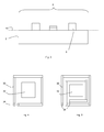
- loop does not imply that the loop needs to be a closed loop. See the possible alternative arrangements in Figures 4 and 5 . Note that the loop is not a complete ring since the loop needs to have contacts 34 formed at the ends of it.
- the loop can be less than a full turn ( Figure 4 ) or more than a full turn ( Figure 5 ).
- FIG. 6 A further alternative arrangement is shown in Figure 6 .
- a magnetic material used is in single domain state
- a plurality of magnetic elements can be used as shown in Figure 6 .
- the separation between them should be kept at 2a (or more) so that there is not electromagnetic interaction between them and anti-ferromagnetic ordering sets in.
- the distance should be 2r.
Abstract
Description
- The invention relates to an inductor integrated in a semiconductor chip and a method for its manufacture.
- Inductors are important elements of integrated circuits in a wide and diverse range of applications. For example, inductors are used in signal processing circuits such as high-pass filters, resonant tank circuits and Butterworth filters in communication systems. Additional applications include impedance matching network topologies in radio frequency (RF) transceiver circuits. Efficient integrated transformers for dc/dc converters in hybrid electric vehicles also require integrated micro-coils. In inductive power transfer systems for radio frequency identification (RFID) devices and embedded biomedical implants integrated coils are key elements. Micro electro-mechanical systems (MEMS) resonators and magnetic sensors also require high quality integrated inductors.
- Ideally, inductors should be integrated with system electronics at a system design level. However, traditionally inductors are large auxiliary components which are very difficult to miniaturise. Attempts have been made to eliminate inductors in communication systems by simulating their action by active element. However, this approach can be unsuccessful as it introduces more parasitics and often generates more noise than actual inductors.
- When unable to eliminate inductors designers use integrated two-dimensional spiral inductors that are fabricated on the same substrate as the integrated circuits to which they are coupled. Although such inductors can be manufactured by conventional integrated circuit manufacturing, they typically suffer from low inductance, low quality factor and typically consume a large share of surface area.
- It would therefore be advantageous to integrate the manufacturing of an inductor with the manufacture of an integrated circuit in an improved way. There is a particular need to fabricate inductors for high frequency applications.
- Integrated circuit manufacture is a very advanced technology. The process steps can be divided into the front end of line (FEOL) and the back end of line (BEOL). The front end of line is the set of process steps up to the first metallization layer, and the back end of line is the remainder of the steps. The front end of line manufactures a wide variety of active and passive semiconductor devices on a chip; the back end of line is used to manufacture interconnects and contacts. Increasingly, more than one level of interconnect may be used.
- According to the invention, there is provided a method of making an inductor on a chip according to claim 1.
- The invention exploits the properties of micrometre or sub-micrometre magnetic elements. They have a higher ferromagnetic resonant frequency compared with their bulk counterparts, so they can be used in a broader frequency range, typically extending into the GHz region. The magnetic permeability is increased compared to the bulk values, and the dissipative part of the permeability reduced. Noise is also reduced.
- For these reason, very small magnetic elements are very well suited to providing enhanced inductances on a chip.
- The inductances can easily be manufactured in a way compatible with conventional back end processing. There is no need for any changes to manufacture up to the metallization layer used to form the loop.
- The invention also relates to a semiconductor chip with an inductor according to claim 9.
- For a better understanding of the invention, embodiments will be described, purely by way of example, with reference to the accompanying drawings, in which
-
Figure 1 shows in side view a first stage in the manufacture of an embodiment of the invention; -
Figure 2 shows in side view a second stage in the manufacture of the embodiment; -
Figure 3 shows in side view a third stage in the manufacture of the embodiment; -
Figure 4 shows in top view the stage shown inFigure 3 ; and -
Figure 5 shows a top view of an alternative layout; and -
Figure 6 shows a top view of a further alternative layout. - The figures are schematic and not to scale. In particular, the vertical direction in the side views is greatly exaggerated.
- Referring to
Figure 1 , an integratedcircuit 2 is manufactured to the end of the FEOL to have a plurality ofsemiconductor devices 4 and ametallization layer 6. In the example, themetallization layer 6 is of AI. - The metallization layer is patterned as usual in regions of the integrated
circuit 2 with a semiconductor device and in theregion 8 for forming an inductor themetallization layer 6 is patterned to form aloop 30 as illustrated inFigure 3 . The loop is in theplane 10 of the integrated circuit, the plane being indicated inFigure 1 . - Then, a refractory metal layer 12 is deposited over the full surface of the semiconductor device, followed by a magnetic thin film 14 and a protection layer 16. The functions of these layers are described below. The refractory metal layer 12 and magnetic thin film 14 may in particular be deposited by a sputtering process.
- A photoresist layer 18 is then deposited and patterned to leave photoresist only on a
magnetic element 32 at the centre of the loop, resulting in the arrangement shown inFigure 1 . - The photoresist is then used as a mask in a Chlorine based reactive ion etch process which leaves the triple layer structure of refractory metal layer 12, magnetic thin film 14 and protection layer 16 in the
magnetic element 32 in the centre of the loop. The photoresist is then removed. - The size of the
magnetic element 32 is chosen to be small, to allow theloop 30 and magnetic core constituted by the magnetic element of the magnetic film to have desirable properties, in particular to operate at high frequencies. The physical considerations behind this will now be discussed. - It is known that when a magnetic material is subjected to a magnetic field oscillating at frequency ω, its response is described by a complex magnetic permeability χ(ω)= χM (ω)- jχD (ω) where j is

- In case of bulk magnetic materials, the complex permeability χ (ω) is determined by the intrinsic material properties. On the other hand, the complex permeability of thin magnetic films already significantly differs compared to a bulk specimen with the same composition. Furthermore, by introducing lateral dimensions constraints the properties of a magnetic material can be substantially altered compared to the original bulk material, as well as to thin magnetic films. These changes in the magnetic properties come about due to a substantial modification in magnetic ordering caused by reduced dimensionality.
- The general inductive properties of thin current loops are known from textbooks such as S. Ramo, J. R. Whinnery and T. VanDuzer, Fields and Waves in Communication Electronics, John Wiley & Sons, Inc. Third Edition, 1994 and W. R. Smythe, Static and Dynamic Electricity, McGraw-Hill Book Company, Second Edition, 1950.
- Integrating a suitable core of magnetic film into the loop can act as a flux-amplifying component., By reducing flux leakage the effective inductance of the coil will increase while the unwanted Ohmic losses will be reduced achieving a high quality factor Q defined as:

- A suitable magnetic material used in on-chip RF integrated inductors must accordingly exhibit high permeability and low magnetic loss in high-frequency range as well as process compatibility with IC processes. Relative permeability (µr) and specific resistivity p of a magnetic material are the key parameters. Due to losses in the ferromagnetic material the intrinsic permeability is a complex quantity with a clear frequency dependence defined as:
 is the real component of the series complex permeability, which represents the magnetic performance and consequently contributes to the inductance L of the integrated coil, while
 is the imaginary part of the complex permeability and determines the magnetic loss of the material.
- At low frequencies for typical ferrite materialsis much larger than
 For conventional ferrite cores used in transformer applications such as pot core and cylindrical cores it is true that the magnetic losses will increase at high frequencies in the GHz region as ferrite shows a low ferromagnetic resonance frequency fM which is hard to exceed 800MHz.
- Here it needs to be emphasized that for bulk materials both the real and imaginary parts of the complex permeability, as well as ferromagnetic resonance frequency, are governed solely by the material composition. However, when the dimensions of a magnetic structure (thickness, lateral dimensions) become comparable to the average ferromagnetic domain size, the complex permeability becomes strongly dependent on the size, as well. As a result, the size can be used as a efficient means to tailor the relevant properties of a magnetic element.
- The high frequency characteristics of permalloy (NiFe) and FeCo thin magnetic films have been investigated by N X Sun et al, IEEE Tran Magnetics, volume 38, number 1, 2002. The -3dB cut-off frequency is 1.5 GHz. This analysis has been performed on a multi-domain thin film, where magnetic domains are present and magnetic switching occurs through Neel wall rotation. Neel domain walls are in-plane of a thin magnetic film, unlike bulk domain walls (Bloch walls), where magnetization switching occurs out of the film's plane. The presence of Neel walls adds a dumping-like component to the dynamics of the system and limits its cut-off frequency.
- As opposed to multi-domain thin magnetic films, magnetic thin films with (sub-) micrometre lateral dimensions are in a single domain state, as formation of a domain wall is energetically less favourable than stray magnetic fields associated with the single domain state. For example, L Giovannini et al, Phys Rev. B, volume 70, 172404, 2004, study the dynamic behaviour of FeNi (permalloy) magnetic disks has been studied. In contrast to the multi-domain films these disks are in the single-domain state, which implies that their dynamics is determined only by spin dynamics and its interactions with lattice, as well as Zeeman and many-body spin and electron interactions. As a result, the cut-off frequency increases dramatically to above 10GHz.
- A significant increase in the cut-off frequency by means of reducing only the lateral dimensions of ferromagnetic thin films has been demonstrated in P. Wang et al, IEEE Tran Magnetics, volume 45, no 1, pp 71-74 (2009), wherein ferromagnetic resonance frequency of a thin permalloy film has been increased from about 8 GHz to 11.5 GHz just by reducing its width from 550 nm to 240 nm.
- The inventors have realised that as a result thin-film soft ferromagnetic materials and in particular thin soft magnetic films with (sub -) micrometre lateral dimensions and hence a single magnetic domain (or only a few domains) are suitable for operation in a broad range of frequencies. Thus, the lateral dimension of the or each magnetic element (32) is chosen such that each magnetic element only has a few domains, or preferably exactly one single domain.
- The concept works with a wide variety of magnetic materials. Thin film magnetic materials that combine high permeability, good thermal stability, high saturation magnetization, high resistivity, good high-frequency properties, and are silicon process compatible such as are suitable for high frequency inductors.
- For ease of processing, relatively well known materials such FexNi1-x alloy, known as permalloy, may be brought into a single domain state, which allows for high frequency operationm, with thin films of up to 100 nm thickness and lateral dimensions in sub-micrometre regime. As abovementioned, it is possible to exceed 10 GHz -3 dB frequency. Cobalt is a possible alternative.
- More advanced materials may be used, for example CoZrTa and Ni-Zn(-Co) . These allow for a wider range of possibilities. In particular, it possible using a variety of materials to adjust the properties far more - permalloy is generally used in a form with 80% Ni and 20% Fe and so the bulk properties are fixed. By using ternary materials such as CoZrTa alloy there is a much greater flexibility in the exact alloy composition which allows the exact properties to be tailored to meet requirements. In particular, it may be possible to adjust both the real and imagineary parts of the magnetic permeability with suitable choices of materials, which can in particular allow the degree of loss to be controlled. The choice of such materials may also allow the temperature dependence to be controlled.
- Accordingly it is possible to significantly improve fM and reducewith only slightly compromising the overall magnetic permeability of the material µr

- The smaller laterally constrained cores used in the present invention have a number of advantages over bulk materials. Most importantly, the ferromagnetic resonant frequency fM is increased allowing the inductor core to operate into the GHz range. Further, however, the modulus of the magnetic permeability χ (ω) is itself increased, and the dissipative part of the permeability χD (ω) is decreased.
- The noise contribution from Barkhausen noise is also significantly reduced.
- For example, a planar 1 µm square
central area 32 of magnetic material within and surrounded by a loop with 0.3 µm wide metal lines raises the inductance of the loop from about 1 pH to 0.1 nH, a factor of a hundred. This greatly reduces the area to provide inductances on chip with the improved properties discussed above. - The use of the refractory metal layer 12 under the magnetic region has a number of effects. Firstly, it improves the adhesion of the magnetic film to the inter-metal dielectric which forms the surface of the
chip 2. Secondly, it acts as a diffusion barrier which may be important if the magnetic film contains fast diffusers, for example in an alloy. Thirdly, the refractory metal layer 12 may set the texture of the subsequently deposited films, which may be used to tailor the magnetic properties. However, the refractory metal layer 12 is not absolutely essential to the operation of the invention and may be omitted if not required. - The protection layer 16 simply protects the magnetic film. For experimental laboratory purposes gold may be used. For commercial integrated circuit manufacture gold is generally not allowed so standard BEOL refractory metals (compounds) such as TiN or TaN may be used.
- The term "loop" does not imply that the loop needs to be a closed loop. See the possible alternative arrangements in
Figures 4 and 5 . Note that the loop is not a complete ring since the loop needs to havecontacts 34 formed at the ends of it. The loop can be less than a full turn (Figure 4 ) or more than a full turn (Figure 5 ). - A further alternative arrangement is shown in
Figure 6 . In order to ensure that a magnetic material used is in single domain state, instead of one magnetic element a plurality of magnetic elements can be used as shown inFigure 6 . Assuming the lateral dimensions of the squares shown are a, the separation between them should be kept at 2a (or more) so that there is not electromagnetic interaction between them and anti-ferromagnetic ordering sets in. The same applies for circular magnetic elements with radius r, the distance should be 2r. - By using a plurality of magnetic elements the benefits of small magnetic element size can be used even for loops of larger size and larger inductance.
Claims (15)
- A method of making an inductor on a chip, comprising:manufacturing an integrated circuit chip (2) on a substrate to a step with a metallization layer (6) formed, the integrated circuit chip (2) including a plurality of semiconductor devices (4);defining a loop (30) extending in the plane (10) of the chip in the metallization layer (6);depositing a layer of magnetic material (14);depositing and patterning resist (18) over the layer of magnetic material to define the area of at least one magnetic element (32) within the loop;etching to remove the magnetic material (14) except where protected by the resist; andremoving the resist to leave the loop (30) in the metallization layer (6) around at least one magnetic element (32) of the magnetic material (14), the or each magnetic element (32) having lateral dimensions such that includes no more than five magnetic domains.
- A method according to claim 1 wherein the or each magnetic element (32) includes a single magnetic domain.
- A method according to claim 1 or 2 wherein the lateral dimension of the or each magnetic element (32) is no more than 1 µm.
- A method according to any preceding claim, further comprising depositing a refractory metal layer (12) over the surface of the chip after the step of defining a loop (30) and before the step of depositing a layer of magnetic material (14), wherein the step of etching also removes the refractory metal (12) except where protected by the resist (18).
- A method according to any preceding claim, further comprising depositing a protection layer (16) over the layer of magnetic material (14), wherein the step of etching also removes the protection layer (16) except where protected by the resist.
- A method according to any preceding claim, wherein the step of etching uses a dry chlorine etch.
- A method according to any preceding claim wherein the magnetic material is an alloy of Fe and Ni.
- A method according to any preceding claim wherein the steps of depositing and patterning resist (18) and etching define a plurality of magnetic elements (32) within the loop (10), the magnetic elements being spaced apart to have a gap between adjacent elements of at least double the largest lateral dimension of each magnetic element.
- A semiconductor chip, comprising:a plurality of semiconductor devices (4) formed on a substrate;a metallization layer (6) over the substrate, the metallization layer including at least one loop (30) forming an inductor; anda magnetic material (14) formed as at least one magnetic element (32) within the loop, the magnetic element having lateral dimensions such that includes no more than five magnetic domains.
- A semiconductor chip according to claim 9 wherein the or each magnetic element includes a single magnetic domain.
- A semiconductor chip according to claim 9 or 10 wherein the lateral dimension of the or each magnetic element is no more than 1 µm.
- A semiconductor chip according to any of claims 9 to 11, further comprising a layer of refractory metal (12) under the magnetic material (14).
- A semiconductor chip according to any of claims 9 to 12, further comprising a protection layer (16) above the magnetic material (14).
- A semiconductor chip according to any of claims 9 to 13 wherein the magnetic material (14) is an alloy of Fe and Ni.
- A semiconductor chip according to any of claims 9 to 14, including a plurality of magnetic elements (32) within the loop (10), the magnetic elements being spaced apart to have a gap between adjacent elements of at least double the largest lateral dimension of each magnetic element.
Priority Applications (4)
| Application Number | Priority Date | Filing Date | Title |
|---|---|---|---|
| EP09179745.6A EP2337063B1 (en) | 2009-12-17 | 2009-12-17 | On chip integrated inductor and manufacturing method therefor |
| PCT/IB2010/055811 WO2011073908A1 (en) | 2009-12-17 | 2010-12-14 | On chip integrated inductor and manufacturing method therefor |
| CN201080056543.5A CN102652348B (en) | 2009-12-17 | 2010-12-14 | On chip integrated inductor and manufacturing method therefor |
| US13/513,834 US20120248570A1 (en) | 2009-12-17 | 2010-12-14 | On chip integrated inductor |
Applications Claiming Priority (1)
| Application Number | Priority Date | Filing Date | Title |
|---|---|---|---|
| EP09179745.6A EP2337063B1 (en) | 2009-12-17 | 2009-12-17 | On chip integrated inductor and manufacturing method therefor |
Publications (2)
| Publication Number | Publication Date |
|---|---|
| EP2337063A1 true EP2337063A1 (en) | 2011-06-22 |
| EP2337063B1 EP2337063B1 (en) | 2013-10-23 |
Family
ID=42101435
Family Applications (1)
| Application Number | Title | Priority Date | Filing Date |
|---|---|---|---|
| EP09179745.6A Not-in-force EP2337063B1 (en) | 2009-12-17 | 2009-12-17 | On chip integrated inductor and manufacturing method therefor |
Country Status (4)
| Country | Link |
|---|---|
| US (1) | US20120248570A1 (en) |
| EP (1) | EP2337063B1 (en) |
| CN (1) | CN102652348B (en) |
| WO (1) | WO2011073908A1 (en) |
Families Citing this family (5)
| Publication number | Priority date | Publication date | Assignee | Title |
|---|---|---|---|---|
| EP2915212A4 (en) * | 2012-11-01 | 2016-07-20 | Indian Inst Scient | High-frequency integrated device with an enhanced inductance and a process thereof |
| US9384879B2 (en) | 2014-01-15 | 2016-07-05 | International Business Machines Corporation | Magnetic multilayer structure |
| KR102188450B1 (en) * | 2014-09-05 | 2020-12-08 | 삼성전기주식회사 | Coil unit for power inductor, manufacturing method of coil unit for power inductor, power inductor and manufacturing method of power inductor |
| RU2614188C1 (en) * | 2015-12-01 | 2017-03-23 | Федеральное Государственное Бюджетное Образовательное Учреждение Высшего Профессионального Образования "Донской Государственный Технический Университет" (Дгту) | Planar inductance |
| US11373803B2 (en) * | 2017-08-11 | 2022-06-28 | Applied Materials, Inc. | Method of forming a magnetic core on a substrate |
Citations (4)
| Publication number | Priority date | Publication date | Assignee | Title |
|---|---|---|---|---|
| US6396122B1 (en) * | 2000-09-08 | 2002-05-28 | Newport Fab, Llc | Method for fabricating on-chip inductors and related structure |
| US6441715B1 (en) * | 1999-02-17 | 2002-08-27 | Texas Instruments Incorporated | Method of fabricating a miniaturized integrated circuit inductor and transformer fabrication |
| US20040263310A1 (en) * | 2003-06-30 | 2004-12-30 | International Business Machines Corporation | On-chip inductor with magnetic core |
| US20050133924A1 (en) * | 1999-11-23 | 2005-06-23 | Crawford Ankur M. | Magnetic layer processing |
Family Cites Families (4)
| Publication number | Priority date | Publication date | Assignee | Title |
|---|---|---|---|---|
| US5227659A (en) * | 1990-06-08 | 1993-07-13 | Trustees Of Boston University | Integrated circuit inductor |
| CA2072277A1 (en) * | 1991-07-03 | 1993-01-04 | Nobuo Shiga | Inductance element |
| JP3745316B2 (en) * | 2002-06-24 | 2006-02-15 | Necエレクトロニクス株式会社 | Semiconductor integrated circuit and manufacturing method thereof |
| WO2007131967A1 (en) * | 2006-05-15 | 2007-11-22 | Koninklijke Philips Electronics N.V. | Integrated low-loss capacitor-arrray structure |
-
2009
- 2009-12-17 EP EP09179745.6A patent/EP2337063B1/en not_active Not-in-force
-
2010
- 2010-12-14 WO PCT/IB2010/055811 patent/WO2011073908A1/en active Application Filing
- 2010-12-14 US US13/513,834 patent/US20120248570A1/en not_active Abandoned
- 2010-12-14 CN CN201080056543.5A patent/CN102652348B/en not_active Expired - Fee Related
Patent Citations (4)
| Publication number | Priority date | Publication date | Assignee | Title |
|---|---|---|---|---|
| US6441715B1 (en) * | 1999-02-17 | 2002-08-27 | Texas Instruments Incorporated | Method of fabricating a miniaturized integrated circuit inductor and transformer fabrication |
| US20050133924A1 (en) * | 1999-11-23 | 2005-06-23 | Crawford Ankur M. | Magnetic layer processing |
| US6396122B1 (en) * | 2000-09-08 | 2002-05-28 | Newport Fab, Llc | Method for fabricating on-chip inductors and related structure |
| US20040263310A1 (en) * | 2003-06-30 | 2004-12-30 | International Business Machines Corporation | On-chip inductor with magnetic core |
Non-Patent Citations (3)
| Title |
|---|
| GAMET E ET AL: "Simulation of the contribution of magnetic films on planar inductors characteristics", JOURNAL OF MAGNETISM AND MAGNETIC MATERIALS, ELSEVIER SCIENCE PUBLISHERS, AMSTERDAM, NL, vol. 288, 1 March 2005 (2005-03-01), pages 121 - 129, XP025364520, ISSN: 0304-8853, [retrieved on 20050301] * |
| HIROHATA A ET AL: "Magnetic Domain Evolution in Permalloy Mesoscopic Dots", IEEE TRANSACTIONS ON MAGNETICS, IEEE SERVICE CENTER, NEW YORK, NY, US LNKD- DOI:10.1109/20.800697, vol. 35, no. 5, 1 September 1999 (1999-09-01), pages 3886 - 3888, XP011087509, ISSN: 0018-9464 * |
| PINGSHAN WANG ET AL: "Tailoring High-Frequency Properties of Permalloy Films by Submicrometer Patterning", IEEE TRANSACTIONS ON MAGNETICS, IEEE SERVICE CENTER, NEW YORK, NY, US, vol. 42, no. 1, 1 January 2009 (2009-01-01), pages 71 - 74, XP011243438, ISSN: 0018-9464 * |
Also Published As
| Publication number | Publication date |
|---|---|
| CN102652348B (en) | 2015-07-15 |
| US20120248570A1 (en) | 2012-10-04 |
| EP2337063B1 (en) | 2013-10-23 |
| WO2011073908A1 (en) | 2011-06-23 |
| CN102652348A (en) | 2012-08-29 |
Similar Documents
| Publication | Publication Date | Title |
|---|---|---|
| US6191468B1 (en) | Inductor with magnetic material layers | |
| Gardner et al. | Review of on-chip inductor structures with magnetic films | |
| US7791837B2 (en) | Thin film device having thin film coil wound on magnetic film | |
| Crawford et al. | High-frequency microinductors with amorphous magnetic ground planes | |
| KR100633497B1 (en) | On-chip inductor with magnetic core | |
| EP2337063B1 (en) | On chip integrated inductor and manufacturing method therefor | |
| TWI363359B (en) | Inductor with exchange-coupling film | |
| US20070230049A1 (en) | Thin film device | |
| US6873242B2 (en) | Magnetic component | |
| KR100742555B1 (en) | Magnetic thin film for high frequency and its production method, and magnetic element | |
| Ni et al. | Permalloy patterning effects on RF inductors | |
| US6529110B2 (en) | Microcomponent of the microinductor or microtransformer type | |
| Yamaguchi et al. | Magnetic RF integrated thin-film inductors | |
| WO2022120319A2 (en) | Magnetic core with hard ferromagnetic biasing layers and structures containing same | |
| Ludwig et al. | High-frequency magnetoelastic multilayer thin films and applications | |
| US20080106364A1 (en) | Spiral-shaped closed magnetic core and integrated micro-inductor comprising one such closed magnetic core | |
| EP1542261B1 (en) | Method of producing an element comprising an electrical conductor encircled by magnetic material | |
| US7432792B2 (en) | High frequency thin film electrical circuit element | |
| KR100818994B1 (en) | Fabricating method for semiconductor device | |
| KR100776406B1 (en) | Micro inductor and fabrication method | |
| Hettstedt et al. | Toroid microinductors using segmented magnetic cores | |
| Kim et al. | Substrates and dimension dependence of MEMS Inductors | |
| KR20000059299A (en) | Material of Magnetic Thin Film For Super-high Frequency and Magnetic Thin Film Using The Same and Fabrication Method Thereof |
Legal Events
| Date | Code | Title | Description |
|---|---|---|---|
| PUAI | Public reference made under article 153(3) epc to a published international application that has entered the european phase |
Free format text: ORIGINAL CODE: 0009012 |
|
| AK | Designated contracting states |
Kind code of ref document: A1 Designated state(s): AT BE BG CH CY CZ DE DK EE ES FI FR GB GR HR HU IE IS IT LI LT LU LV MC MK MT NL NO PL PT RO SE SI SK SM TR |
|
| AX | Request for extension of the european patent |
Extension state: AL BA RS |
|
| 17P | Request for examination filed |
Effective date: 20111222 |
|
| 17Q | First examination report despatched |
Effective date: 20130103 |
|
| REG | Reference to a national code |
Ref country code: DE Ref legal event code: R079 Ref document number: 602009019588 Country of ref document: DE Free format text: PREVIOUS MAIN CLASS: H01L0021020000 Ipc: H01L0049020000 |
|
| RIC1 | Information provided on ipc code assigned before grant |
Ipc: H01L 49/02 20060101AFI20130517BHEP Ipc: H01F 41/04 20060101ALI20130517BHEP Ipc: H01L 23/522 20060101ALI20130517BHEP Ipc: H01L 23/64 20060101ALI20130517BHEP Ipc: H01F 17/00 20060101ALI20130517BHEP Ipc: H01L 21/02 20060101ALI20130517BHEP |
|
| GRAP | Despatch of communication of intention to grant a patent |
Free format text: ORIGINAL CODE: EPIDOSNIGR1 |
|
| INTG | Intention to grant announced |
Effective date: 20130705 |
|
| GRAS | Grant fee paid |
Free format text: ORIGINAL CODE: EPIDOSNIGR3 |
|
| GRAA | (expected) grant |
Free format text: ORIGINAL CODE: 0009210 |
|
| AK | Designated contracting states |
Kind code of ref document: B1 Designated state(s): AT BE BG CH CY CZ DE DK EE ES FI FR GB GR HR HU IE IS IT LI LT LU LV MC MK MT NL NO PL PT RO SE SI SK SM TR |
|
| REG | Reference to a national code |
Ref country code: GB Ref legal event code: FG4D |
|
| REG | Reference to a national code |
Ref country code: CH Ref legal event code: EP |
|
| REG | Reference to a national code |
Ref country code: AT Ref legal event code: REF Ref document number: 637987 Country of ref document: AT Kind code of ref document: T Effective date: 20131115 |
|
| REG | Reference to a national code |
Ref country code: IE Ref legal event code: FG4D |
|
| REG | Reference to a national code |
Ref country code: DE Ref legal event code: R096 Ref document number: 602009019588 Country of ref document: DE Effective date: 20131219 |
|
| REG | Reference to a national code |
Ref country code: NL Ref legal event code: VDEP Effective date: 20131023 |
|
| REG | Reference to a national code |
Ref country code: AT Ref legal event code: MK05 Ref document number: 637987 Country of ref document: AT Kind code of ref document: T Effective date: 20131023 |
|
| REG | Reference to a national code |
Ref country code: LT Ref legal event code: MG4D |
|
| PG25 | Lapsed in a contracting state [announced via postgrant information from national office to epo] |
Ref country code: FI Free format text: LAPSE BECAUSE OF FAILURE TO SUBMIT A TRANSLATION OF THE DESCRIPTION OR TO PAY THE FEE WITHIN THE PRESCRIBED TIME-LIMIT Effective date: 20131023 Ref country code: BE Free format text: LAPSE BECAUSE OF FAILURE TO SUBMIT A TRANSLATION OF THE DESCRIPTION OR TO PAY THE FEE WITHIN THE PRESCRIBED TIME-LIMIT Effective date: 20131023 Ref country code: NO Free format text: LAPSE BECAUSE OF FAILURE TO SUBMIT A TRANSLATION OF THE DESCRIPTION OR TO PAY THE FEE WITHIN THE PRESCRIBED TIME-LIMIT Effective date: 20140123 Ref country code: SE Free format text: LAPSE BECAUSE OF FAILURE TO SUBMIT A TRANSLATION OF THE DESCRIPTION OR TO PAY THE FEE WITHIN THE PRESCRIBED TIME-LIMIT Effective date: 20131023 Ref country code: LT Free format text: LAPSE BECAUSE OF FAILURE TO SUBMIT A TRANSLATION OF THE DESCRIPTION OR TO PAY THE FEE WITHIN THE PRESCRIBED TIME-LIMIT Effective date: 20131023 Ref country code: NL Free format text: LAPSE BECAUSE OF FAILURE TO SUBMIT A TRANSLATION OF THE DESCRIPTION OR TO PAY THE FEE WITHIN THE PRESCRIBED TIME-LIMIT Effective date: 20131023 Ref country code: HR Free format text: LAPSE BECAUSE OF FAILURE TO SUBMIT A TRANSLATION OF THE DESCRIPTION OR TO PAY THE FEE WITHIN THE PRESCRIBED TIME-LIMIT Effective date: 20131023 Ref country code: IS Free format text: LAPSE BECAUSE OF FAILURE TO SUBMIT A TRANSLATION OF THE DESCRIPTION OR TO PAY THE FEE WITHIN THE PRESCRIBED TIME-LIMIT Effective date: 20140223 |
|
| PG25 | Lapsed in a contracting state [announced via postgrant information from national office to epo] |
Ref country code: AT Free format text: LAPSE BECAUSE OF FAILURE TO SUBMIT A TRANSLATION OF THE DESCRIPTION OR TO PAY THE FEE WITHIN THE PRESCRIBED TIME-LIMIT Effective date: 20131023 Ref country code: ES Free format text: LAPSE BECAUSE OF FAILURE TO SUBMIT A TRANSLATION OF THE DESCRIPTION OR TO PAY THE FEE WITHIN THE PRESCRIBED TIME-LIMIT Effective date: 20131023 Ref country code: LV Free format text: LAPSE BECAUSE OF FAILURE TO SUBMIT A TRANSLATION OF THE DESCRIPTION OR TO PAY THE FEE WITHIN THE PRESCRIBED TIME-LIMIT Effective date: 20131023 Ref country code: CY Free format text: LAPSE BECAUSE OF FAILURE TO SUBMIT A TRANSLATION OF THE DESCRIPTION OR TO PAY THE FEE WITHIN THE PRESCRIBED TIME-LIMIT Effective date: 20131023 |
|
| PG25 | Lapsed in a contracting state [announced via postgrant information from national office to epo] |
Ref country code: PT Free format text: LAPSE BECAUSE OF FAILURE TO SUBMIT A TRANSLATION OF THE DESCRIPTION OR TO PAY THE FEE WITHIN THE PRESCRIBED TIME-LIMIT Effective date: 20140224 |
|
| REG | Reference to a national code |
Ref country code: DE Ref legal event code: R097 Ref document number: 602009019588 Country of ref document: DE |
|
| PG25 | Lapsed in a contracting state [announced via postgrant information from national office to epo] |
Ref country code: EE Free format text: LAPSE BECAUSE OF FAILURE TO SUBMIT A TRANSLATION OF THE DESCRIPTION OR TO PAY THE FEE WITHIN THE PRESCRIBED TIME-LIMIT Effective date: 20131023 |
|
| REG | Reference to a national code |
Ref country code: CH Ref legal event code: PL |
|
| PG25 | Lapsed in a contracting state [announced via postgrant information from national office to epo] |
Ref country code: CZ Free format text: LAPSE BECAUSE OF FAILURE TO SUBMIT A TRANSLATION OF THE DESCRIPTION OR TO PAY THE FEE WITHIN THE PRESCRIBED TIME-LIMIT Effective date: 20131023 Ref country code: MC Free format text: LAPSE BECAUSE OF FAILURE TO SUBMIT A TRANSLATION OF THE DESCRIPTION OR TO PAY THE FEE WITHIN THE PRESCRIBED TIME-LIMIT Effective date: 20131023 Ref country code: RO Free format text: LAPSE BECAUSE OF FAILURE TO SUBMIT A TRANSLATION OF THE DESCRIPTION OR TO PAY THE FEE WITHIN THE PRESCRIBED TIME-LIMIT Effective date: 20131023 Ref country code: PL Free format text: LAPSE BECAUSE OF FAILURE TO SUBMIT A TRANSLATION OF THE DESCRIPTION OR TO PAY THE FEE WITHIN THE PRESCRIBED TIME-LIMIT Effective date: 20131023 Ref country code: SK Free format text: LAPSE BECAUSE OF FAILURE TO SUBMIT A TRANSLATION OF THE DESCRIPTION OR TO PAY THE FEE WITHIN THE PRESCRIBED TIME-LIMIT Effective date: 20131023 Ref country code: IT Free format text: LAPSE BECAUSE OF FAILURE TO SUBMIT A TRANSLATION OF THE DESCRIPTION OR TO PAY THE FEE WITHIN THE PRESCRIBED TIME-LIMIT Effective date: 20131023 Ref country code: LU Free format text: LAPSE BECAUSE OF FAILURE TO SUBMIT A TRANSLATION OF THE DESCRIPTION OR TO PAY THE FEE WITHIN THE PRESCRIBED TIME-LIMIT Effective date: 20131217 |
|
| PLBE | No opposition filed within time limit |
Free format text: ORIGINAL CODE: 0009261 |
|
| STAA | Information on the status of an ep patent application or granted ep patent |
Free format text: STATUS: NO OPPOSITION FILED WITHIN TIME LIMIT |
|
| GBPC | Gb: european patent ceased through non-payment of renewal fee |
Effective date: 20140123 |
|
| REG | Reference to a national code |
Ref country code: IE Ref legal event code: MM4A |
|
| REG | Reference to a national code |
Ref country code: FR Ref legal event code: ST Effective date: 20140829 |
|
| PG25 | Lapsed in a contracting state [announced via postgrant information from national office to epo] |
Ref country code: DK Free format text: LAPSE BECAUSE OF FAILURE TO SUBMIT A TRANSLATION OF THE DESCRIPTION OR TO PAY THE FEE WITHIN THE PRESCRIBED TIME-LIMIT Effective date: 20131023 |
|
| 26N | No opposition filed |
Effective date: 20140724 |
|
| PG25 | Lapsed in a contracting state [announced via postgrant information from national office to epo] |
Ref country code: IE Free format text: LAPSE BECAUSE OF NON-PAYMENT OF DUE FEES Effective date: 20131217 Ref country code: CH Free format text: LAPSE BECAUSE OF NON-PAYMENT OF DUE FEES Effective date: 20131231 Ref country code: LI Free format text: LAPSE BECAUSE OF NON-PAYMENT OF DUE FEES Effective date: 20131231 |
|
| REG | Reference to a national code |
Ref country code: DE Ref legal event code: R097 Ref document number: 602009019588 Country of ref document: DE Effective date: 20140724 |
|
| PG25 | Lapsed in a contracting state [announced via postgrant information from national office to epo] |
Ref country code: GB Free format text: LAPSE BECAUSE OF NON-PAYMENT OF DUE FEES Effective date: 20140123 Ref country code: FR Free format text: LAPSE BECAUSE OF NON-PAYMENT OF DUE FEES Effective date: 20131231 |
|
| PGFP | Annual fee paid to national office [announced via postgrant information from national office to epo] |
Ref country code: DE Payment date: 20141121 Year of fee payment: 6 |
|
| PG25 | Lapsed in a contracting state [announced via postgrant information from national office to epo] |
Ref country code: SI Free format text: LAPSE BECAUSE OF FAILURE TO SUBMIT A TRANSLATION OF THE DESCRIPTION OR TO PAY THE FEE WITHIN THE PRESCRIBED TIME-LIMIT Effective date: 20131023 |
|
| PG25 | Lapsed in a contracting state [announced via postgrant information from national office to epo] |
Ref country code: SM Free format text: LAPSE BECAUSE OF FAILURE TO SUBMIT A TRANSLATION OF THE DESCRIPTION OR TO PAY THE FEE WITHIN THE PRESCRIBED TIME-LIMIT Effective date: 20131023 |
|
| PG25 | Lapsed in a contracting state [announced via postgrant information from national office to epo] |
Ref country code: TR Free format text: LAPSE BECAUSE OF FAILURE TO SUBMIT A TRANSLATION OF THE DESCRIPTION OR TO PAY THE FEE WITHIN THE PRESCRIBED TIME-LIMIT Effective date: 20131023 |
|
| PG25 | Lapsed in a contracting state [announced via postgrant information from national office to epo] |
Ref country code: MK Free format text: LAPSE BECAUSE OF FAILURE TO SUBMIT A TRANSLATION OF THE DESCRIPTION OR TO PAY THE FEE WITHIN THE PRESCRIBED TIME-LIMIT Effective date: 20131023 Ref country code: HU Free format text: LAPSE BECAUSE OF FAILURE TO SUBMIT A TRANSLATION OF THE DESCRIPTION OR TO PAY THE FEE WITHIN THE PRESCRIBED TIME-LIMIT; INVALID AB INITIO Effective date: 20091217 Ref country code: BG Free format text: LAPSE BECAUSE OF FAILURE TO SUBMIT A TRANSLATION OF THE DESCRIPTION OR TO PAY THE FEE WITHIN THE PRESCRIBED TIME-LIMIT Effective date: 20131023 |
|
| PG25 | Lapsed in a contracting state [announced via postgrant information from national office to epo] |
Ref country code: GR Free format text: LAPSE BECAUSE OF NON-PAYMENT OF DUE FEES Effective date: 20131023 Ref country code: MT Free format text: LAPSE BECAUSE OF FAILURE TO SUBMIT A TRANSLATION OF THE DESCRIPTION OR TO PAY THE FEE WITHIN THE PRESCRIBED TIME-LIMIT Effective date: 20131023 |
|
| PG25 | Lapsed in a contracting state [announced via postgrant information from national office to epo] |
Ref country code: GR Free format text: LAPSE BECAUSE OF FAILURE TO SUBMIT A TRANSLATION OF THE DESCRIPTION OR TO PAY THE FEE WITHIN THE PRESCRIBED TIME-LIMIT Effective date: 20140124 |
|
| REG | Reference to a national code |
Ref country code: DE Ref legal event code: R119 Ref document number: 602009019588 Country of ref document: DE |
|
| PG25 | Lapsed in a contracting state [announced via postgrant information from national office to epo] |
Ref country code: DE Free format text: LAPSE BECAUSE OF NON-PAYMENT OF DUE FEES Effective date: 20160701 |