EP2336744A1 - Impact Test Fixture With Simulated Centrifugal Force - Google Patents
Impact Test Fixture With Simulated Centrifugal Force Download PDFInfo
- Publication number
- EP2336744A1 EP2336744A1 EP10195671A EP10195671A EP2336744A1 EP 2336744 A1 EP2336744 A1 EP 2336744A1 EP 10195671 A EP10195671 A EP 10195671A EP 10195671 A EP10195671 A EP 10195671A EP 2336744 A1 EP2336744 A1 EP 2336744A1
- Authority
- EP
- European Patent Office
- Prior art keywords
- rotor blade
- guide rail
- bearing
- force
- rotor
- Prior art date
- Legal status (The legal status is an assumption and is not a legal conclusion. Google has not performed a legal analysis and makes no representation as to the accuracy of the status listed.)
- Granted
Links
Images

Classifications
-
- G—PHYSICS
- G01—MEASURING; TESTING
- G01M—TESTING STATIC OR DYNAMIC BALANCE OF MACHINES OR STRUCTURES; TESTING OF STRUCTURES OR APPARATUS, NOT OTHERWISE PROVIDED FOR
- G01M5/00—Investigating the elasticity of structures, e.g. deflection of bridges or air-craft wings
- G01M5/0016—Investigating the elasticity of structures, e.g. deflection of bridges or air-craft wings of aircraft wings or blades
-
- G—PHYSICS
- G01—MEASURING; TESTING
- G01M—TESTING STATIC OR DYNAMIC BALANCE OF MACHINES OR STRUCTURES; TESTING OF STRUCTURES OR APPARATUS, NOT OTHERWISE PROVIDED FOR
- G01M5/00—Investigating the elasticity of structures, e.g. deflection of bridges or air-craft wings
- G01M5/0041—Investigating the elasticity of structures, e.g. deflection of bridges or air-craft wings by determining deflection or stress
- G01M5/005—Investigating the elasticity of structures, e.g. deflection of bridges or air-craft wings by determining deflection or stress by means of external apparatus, e.g. test benches or portable test systems
- G01M5/0058—Investigating the elasticity of structures, e.g. deflection of bridges or air-craft wings by determining deflection or stress by means of external apparatus, e.g. test benches or portable test systems of elongated objects, e.g. pipes, masts, towers or railways
-
- G—PHYSICS
- G01—MEASURING; TESTING
- G01N—INVESTIGATING OR ANALYSING MATERIALS BY DETERMINING THEIR CHEMICAL OR PHYSICAL PROPERTIES
- G01N2203/00—Investigating strength properties of solid materials by application of mechanical stress
- G01N2203/0001—Type of application of the stress
- G01N2203/001—Impulsive
-
- Y—GENERAL TAGGING OF NEW TECHNOLOGICAL DEVELOPMENTS; GENERAL TAGGING OF CROSS-SECTIONAL TECHNOLOGIES SPANNING OVER SEVERAL SECTIONS OF THE IPC; TECHNICAL SUBJECTS COVERED BY FORMER USPC CROSS-REFERENCE ART COLLECTIONS [XRACs] AND DIGESTS
- Y10—TECHNICAL SUBJECTS COVERED BY FORMER USPC
- Y10T—TECHNICAL SUBJECTS COVERED BY FORMER US CLASSIFICATION
- Y10T29/00—Metal working
- Y10T29/49—Method of mechanical manufacture
- Y10T29/49998—Work holding
Definitions
- the subject matter disclosed herein relates to impact test fixtures. More specifically, the subject disclosure relates to impact test fixtures for rotating hardware.
- Rotating components for example, helicopter rotor blades
- Testing performed to demonstrate compliance with impact requirements is typically performed on a rotating blade assembly because the force of the impact on the rotor blades is dependent on the natural frequencies of the blade. These natural frequencies depend on the blade mass and the stiffness of the blade which itself is dependent on centrifugal force generated by the rotating blade. Spinning the rotor blade accurately produces the necessary centrifugal force, but such a test is expensive and properly timing the projectile to impact the desired location on the spinning blade is difficult.
- Prior art fixtures have utilized cables, pulleys and/or springs connected to a reinforced portion of the blade which pull the blade radially in an attempt to replicate centrifugal forces in a stationary blade.
- the reinforcement typically includes a laminate buildup on an outboard section of the blade and a cuff bolted thereto to which the cable or other pulling means would be attached. This configuration adds significant weight to the outboard end of the blade which reduces the natural frequency of the blade resulting in an un-conservative reduction in the force of impact.
- the art would well-receive improved testing fixtures and methods which would accurately replicate the centrifugal force while reducing the effects of the fixtures on the impact force resulting from the test.
- a test apparatus for a blade of a rotor includes at least one guide rail located in proximity to the rotor blade and at least one bearing secured to the rotor blade radially outboard of the at least one guide rail.
- the at least one bearing is in operable communication with a radially outboard surface of the at least one guide rail to be translatable thereon.
- At least one force applicator is in operable communication with the at least one guide rail and is configured to exert a force radially outwardly on the at least one guide rail. The force is transferred to the rotor blade via the at least one bearing and simulates a centrifugal force on the rotor blade.
- a method for securing a rotor blade of a rotor in a test fixture includes securing a hub of the rotor in a fixed position and locating at least one guide rail in proximity to the rotor blade. At least one bearing is secured to the rotor blade and is in operable communication with a radially outboard surface of the at least one guide rail to be translatable thereon. A radially outwardly directed force is applied to the at least one guide rail, and the force is transferred to the rotor blade via the at least one bearing. The radially outwardly directed force simulates a centrifugal force on the rotor blade.
- a test apparatus for a specimen includes at least one guide rail located in proximity to the specimen and at least one bearing secured to the specimen.
- the at least one bearing is in operable communication with the at least one guide rail to be translatable thereon.
- At least one force applicator is configured to exert a force on the at least one guide rail. The force is transferred to the specimen via the at least one bearing, the force simulating an operational force on the specimen.
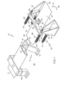
- FIG. 1 is a perspective view of an embodiment of a test fixture
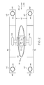
- FIG. 2 is partial cross-sectional view of an embodiment of a test fixture
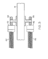
- FIG. 3 is another partial cross-sectional view of an embodiment of a test fixture.
- FIG. 4 is a perspective view of another embodiment of a test fixture.
- the test fixture 10 includes a center support 12 to which a hub 14 of a rotor 16 is fixed.
- the rotor 16 includes a plurality of rotor blades 18 extending radially from the hub 14.
- the rotor 16 shown has two rotor blades 18, but it is to be appreciated that rotors 16 having other quantities of rotor blades 18 may be accommodated by the test fixture 10.
- each rotor blade 18 includes a strap 20 extending along a length of the rotor blade 18 which forms an interior support for the blade shell 22 which forms the exterior of the rotor blade 18.
- the blade shell 22 is formed from, for example, a composite material, while the strap 20 is formed from a metal such as titanium or an alloy thereof. It is to be appreciated, however that the materials described herein are merely exemplary and the use of other materials for the blade shell 22 and/or the strap 20 is contemplated within the scope of the present disclosure.
- the shell 22 is continuous along a length of the rotor blade 18 and may be secured to the strap 20 along the entire length.
- the shell 22 may be segmented into discrete shell segments 24 which extend partially along a length 26 of the rotor blade 18.
- Each shell segment 24 includes one or more attachment points 28 along each shell segment 24 to affix the shell segment 24 to the strap 20 by, for example, a plurality of attachment bolts (not shown).
- the fixture 10 includes a guide assembly 30 located along the rotor blade 18 to be tested.
- the guide assembly 30 is located relative to the hub 14 by affixing the guide assembly 30 to, for example, a plate 32, via at least two guide brackets 34.
- At least one guide bracket 34 is located at each lateral side 36 of the rotor blade 18.
- Two guide rails 40 extend across the rotor blade 18 between the guide brackets 34 with the rotor blade 18 located in a gap 42 (shown in FIG. 2 ) between the two guide rails 40.
- Each guide rail 40 is supported via at least one guide rod 44 extending from each guide bracket 34. In the embodiment of FIG. 1 , the guide rods 44 extend parallel to a length of the rotor blade 18.
- the guide rails 40 include rail holes 46 (shown in FIG. 2 ) extending therethrough through which the guide rods extend to support the guide rails 40.
- An outboard surface 48 of each guide rail 40, located nearest a blade tip 50, includes a curvilinear portion 52 that has a center of curvature 54 at a center of the hub 14.
- At least one bearing 56 is affixed to the rotor blade 18 such that the bearing abuts the curvilinear portion 52.
- the two bearings 56 are utilized, one bearing 56 abutting the curvilinear portion 52 of each of the two guide rails 40.
- the bearing 56 is affixed to the strap 20.
- the bearing 56 is affixed to the rotor blade 18 at an existing attachment point 28 utilized to affix the shell segment 24 to the strap 20.
- the bearing 56 is located at a center of gravity of the rotor blade 18. Locating the bearing at the center of gravity of the rotor blade 18 allows for more accurate representation of a rotating rotor blade 18 with regard to both loads on and stiffness of the rotor blade 18. Utilizing the attachment point 28 eliminates the need to add additional attachment points/structure to accommodate the bearing 56.
- the bearing 56 is a low friction bearing and is configured to move along the curvilinear portion 52 in both an in-plane direction 58 and an out-of-plane direction 60 thus allowing movement of the attached rotor blade 18 in the in-plane direction 58 and the out-of-plane direction 60.
- a force is applied to each guide rail 40 in a direction along each guide rod 44 toward the blade tip 50.
- the force is applied via stacks of Belleville washers 62 which are precompressed and placed on each guide rod 44.
- the washer 62 stacks are retained on each guide rod 44 by, for example a retaining nut 64.
- the washer stacks 62 exert a force on the guide rails 40 which is transferred, via the bearings 56, to the rotor blade 18 and acts in a direction toward the blade tip 50.
- the washer stacks 62 are long to reduce spring rate, and highly compressed to increase the force.
- the desired centrifugal force is 12,000 pounds.
- alternatives to washer stacks 62 may be utilized to apply the force.
- a spring (not shown) located at each guide rod 44 may be used.
- the opposing rotor blade 18 is fixed to react the force applied to the rotor blade 18 to be tested. This may be accomplished by securing the opposing rotor blade 18 to a retaining bracket 66 which is then fixed to the plate 32. The existing attachment points 28 may be utilized to secure the opposing rotor blade 18 to the retaining bracket. In such embodiments, the opposing rotor blade 18 is first secured to the plate 32 via the retaining bracket 66. The simulated centrifugal force is then applied to rotor blade 18 to be tested by, pulling the rotor blade 18 to be tested away from the opposing rotor blade 18.
- the retaining bracket 66 is not utilized.
- a second guide assembly 30 is located at the opposing rotor blade 18, with the same structure as described above.
- the guide rods 44 may extend from the first guide assembly 30 to the second guide assembly 30. It is to be appreciated, however, that separate guide rods 44 may be utilized in each guide assembly 30.
- the simulated centrifugal force is applied to the rotor blade 18, but because of the configuration of the bearings 56 and the guide rails 40, the rotor blade 18 has freedom of motion, subject to the centrifugal force, in in-plane (lead/lag) and out-of-plane (flap) directions which effectively simulates the motion of a rotating rotor blade 18.
- the rotor blade 18 is free to react to the impact in virtually any direction. Such movement of the rotor blade 18 is possible due to the fact that the washer stacks 62 are independent allowing skew of the position of each guide rail 40 relative to the rotor blade 18.
- each guide rail 40 is independent allowing for a change in position of one guide rail 40 relative to the other guide rail 40 in reaction to rotor blade 18 forces from the impact of the projectile during testing.
- the curvilinear shape of each guide rail 40 maintains the simulated centrifugal force in a direction directly radially outwardly from the center of the hub 14, which is representative of a rotating rotor blade 18.
- Such a test fixture 10 provides representative impact testing of a stationary rotor blade 18 to eliminate the need for a costly and complex rotating test.
- use of a flat guide rail 40 would result in changes in direction and changes in magnitude of applied force as the rotor blade 18 moves in-plane along the guide rail 40.
- the use of a curvilinear guide rail 40 has advantages over the cable systems of the prior art in that as the rotor blade moves after impact during testing, the cable would impart an unrealistic restorative force on the rotor blade attempting to recenter the blade.
Abstract
Description
- This is a nonprovisonal application of United States Provisional Application No.
61/287,464, filed on December 17, 2009 - The subject matter disclosed herein relates to impact test fixtures. More specifically, the subject disclosure relates to impact test fixtures for rotating hardware.
- Rotating components, for example, helicopter rotor blades, are exposed to impact with birds, shed ice, objects on the ground and the like. Testing performed to demonstrate compliance with impact requirements is typically performed on a rotating blade assembly because the force of the impact on the rotor blades is dependent on the natural frequencies of the blade. These natural frequencies depend on the blade mass and the stiffness of the blade which itself is dependent on centrifugal force generated by the rotating blade. Spinning the rotor blade accurately produces the necessary centrifugal force, but such a test is expensive and properly timing the projectile to impact the desired location on the spinning blade is difficult.
- Prior art fixtures have utilized cables, pulleys and/or springs connected to a reinforced portion of the blade which pull the blade radially in an attempt to replicate centrifugal forces in a stationary blade. The reinforcement typically includes a laminate buildup on an outboard section of the blade and a cuff bolted thereto to which the cable or other pulling means would be attached. This configuration adds significant weight to the outboard end of the blade which reduces the natural frequency of the blade resulting in an un-conservative reduction in the force of impact. The art would well-receive improved testing fixtures and methods which would accurately replicate the centrifugal force while reducing the effects of the fixtures on the impact force resulting from the test.
- According to one aspect of the invention, a test apparatus for a blade of a rotor includes at least one guide rail located in proximity to the rotor blade and at least one bearing secured to the rotor blade radially outboard of the at least one guide rail. The at least one bearing is in operable communication with a radially outboard surface of the at least one guide rail to be translatable thereon. At least one force applicator is in operable communication with the at least one guide rail and is configured to exert a force radially outwardly on the at least one guide rail. The force is transferred to the rotor blade via the at least one bearing and simulates a centrifugal force on the rotor blade.
- According to another aspect of the invention, a method for securing a rotor blade of a rotor in a test fixture includes securing a hub of the rotor in a fixed position and locating at least one guide rail in proximity to the rotor blade. At least one bearing is secured to the rotor blade and is in operable communication with a radially outboard surface of the at least one guide rail to be translatable thereon. A radially outwardly directed force is applied to the at least one guide rail, and the force is transferred to the rotor blade via the at least one bearing. The radially outwardly directed force simulates a centrifugal force on the rotor blade.
- According to yet another aspect of the invention, a test apparatus for a specimen includes at least one guide rail located in proximity to the specimen and at least one bearing secured to the specimen. The at least one bearing is in operable communication with the at least one guide rail to be translatable thereon. At least one force applicator is configured to exert a force on the at least one guide rail. The force is transferred to the specimen via the at least one bearing, the force simulating an operational force on the specimen.
Particular embodiments of the invention are set out in the following numbered paragraphs: - 1. A test apparatus for a rotor blade of a rotor comprising:
- at least one guide rail disposed in proximity to the rotor blade;
- at least one bearing secured to the rotor blade radially outboard of the at least one guide rail and in operable communication with a radially outboard surface of the at least one guide rail to be translatable thereon; and
at least one force applicator in operable communication with the at least one guide rail configured to exert a force radially outwardly on the at least one guide rail, the radially outwardly directed force transferred to the rotor blade via the at least one bearing, the force simulating a centrifugal force on the rotor blade.
- 2. The test apparatus of Paragraph 1 wherein the at least one guide rail is two guide rails.
- 3. The test apparatus of Paragraph 2 wherein the rotor blade is disposed between the two guide rails.
- 4. The test apparatus of Paragraph 2 or 3 wherein one bearing of the at least one bearing is disposed in operable communication with each guide rail of the two guide rails.
- 5. The test apparatus of any of Paragraphs 1 to 4 wherein the radially outboard surface of each guide rail of the at least one guide rail is curvilinear in shape.
- 6. The test apparatus of Paragraph 5 wherein a center of a radius of curvature of the radially outboard surface is disposed at a central axis of the rotor.
- 7. The test apparatus of any of Paragraphs 1 to 6 wherein two force applicators are disposed in operable communication with each guide rail of the at least one guide rail.
- 8. The test apparatus of any of Paragraphs 1 to 7 wherein the at least one force applicator is a compressed stack of Belleville washers.
- 9. The test apparatus of any of Paragraphs 1 to 8 wherein the at least one bearing is secured to the rotor blade at an attachment point disposed substantially at a center of gravity of the rotor blade.
- 10. The test apparatus of any of Paragraphs 1 to 9 including a retaining bracket secured to an opposing rotor blade to react the force applied to the rotor blade.
- 11. A method for securing a rotor blade of a rotor in a test fixture comprising:
- securing a hub of the rotor in a fixed position;
- locating at least one guide rail in proximity to the rotor blade ;
- securing at least one bearing to the rotor blade and in operable communication with a radially outboard surface of the at least one guide rail to be translatable thereon;
- applying a radially outwardly directed force to the at least one guide rail; and
- transferring the radially outwardly directed force to the rotor blade via the at least one bearing, the radially outwardly directed force simulating a centrifugal force on the rotor blade.
- 12. The method of Paragraph 11 comprising locating the rotor blade between two guide rails of the at least one guide rail.
- 13. The method of
Paragraph 12 wherein one bearing of the at least one bearing is disposed in operable communication with each guide rail of the two guide rails. - 14. The method of any of Paragraphs 11 to 13 wherein the at least one bearing is translatable on a curvilinear portion of the radially outboard surface of each guide rail.
- 15. The method of
Paragraph 14 wherein a center of a radius of curvature of the curvilinear portion is disposed at a central axis of the rotor. - 16. The method of any of Paragraphs 11 to 15 wherein the radially outward force is applied via two force applicators disposed in operable communication with each guide rail of the at least one guide rail.
- 17. The method of Paragraph 16 wherein each force applicator is a compressed stack of Belleville washers.
- 18. The method of Paragraphs 11 to 17 comprising securing the at least one bearing to the rotor blade at an attachment point disposed substantially at a center of gravity of the rotor blade.
- 19. The method of Paragraphs 11 to 18 including retaining an opposing rotor blade of the rotor to react the force applied to the rotor blade.
- These and other advantages and features will become more apparent from the following description taken in conjunction with the drawings.
- The subject matter, which is regarded as the invention, is particularly pointed out and distinctly claimed in the claims at the conclusion of the specification. The foregoing and other features, and advantages of the invention are apparent from the following detailed description taken in conjunction with the accompanying drawings in which:
-
FIG. 1 is a perspective view of an embodiment of a test fixture; -
FIG. 2 is partial cross-sectional view of an embodiment of a test fixture; -
FIG. 3 is another partial cross-sectional view of an embodiment of a test fixture; and -
FIG. 4 is a perspective view of another embodiment of a test fixture. - The detailed description explains embodiments of the invention, together with advantages and features, by way of example with reference to the drawings.
- Referring now to
FIG. 1 , an embodiment of an improvedimpact test fixture 10 for, for example, helicopter rotor blades, is shown. Thetest fixture 10 includes acenter support 12 to which ahub 14 of a rotor 16 is fixed. The rotor 16 includes a plurality ofrotor blades 18 extending radially from thehub 14. In this embodiment, the rotor 16 shown has tworotor blades 18, but it is to be appreciated that rotors 16 having other quantities ofrotor blades 18 may be accommodated by thetest fixture 10. - Referring to
FIG. 2 , eachrotor blade 18 includes astrap 20 extending along a length of therotor blade 18 which forms an interior support for theblade shell 22 which forms the exterior of therotor blade 18. Theblade shell 22 is formed from, for example, a composite material, while thestrap 20 is formed from a metal such as titanium or an alloy thereof. It is to be appreciated, however that the materials described herein are merely exemplary and the use of other materials for theblade shell 22 and/or thestrap 20 is contemplated within the scope of the present disclosure. Referring again toFIG. 1 , theshell 22 is continuous along a length of therotor blade 18 and may be secured to thestrap 20 along the entire length. In some embodiments, including, for example, bearingless rotors, theshell 22 may be segmented intodiscrete shell segments 24 which extend partially along a length 26 of therotor blade 18. Eachshell segment 24 includes one or more attachment points 28 along eachshell segment 24 to affix theshell segment 24 to thestrap 20 by, for example, a plurality of attachment bolts (not shown). - The
fixture 10 includes aguide assembly 30 located along therotor blade 18 to be tested. Theguide assembly 30 is located relative to thehub 14 by affixing theguide assembly 30 to, for example, aplate 32, via at least twoguide brackets 34. At least oneguide bracket 34 is located at eachlateral side 36 of therotor blade 18. Twoguide rails 40 extend across therotor blade 18 between theguide brackets 34 with therotor blade 18 located in a gap 42 (shown inFIG. 2 ) between the twoguide rails 40. Eachguide rail 40 is supported via at least oneguide rod 44 extending from eachguide bracket 34. In the embodiment ofFIG. 1 , theguide rods 44 extend parallel to a length of therotor blade 18. The guide rails 40 include rail holes 46 (shown inFIG. 2 ) extending therethrough through which the guide rods extend to support the guide rails 40. - An
outboard surface 48 of eachguide rail 40, located nearest ablade tip 50, includes acurvilinear portion 52 that has a center ofcurvature 54 at a center of thehub 14. At least onebearing 56 is affixed to therotor blade 18 such that the bearing abuts thecurvilinear portion 52. In some embodiments, as shown inFIG. 3 , the twobearings 56 are utilized, onebearing 56 abutting thecurvilinear portion 52 of each of the twoguide rails 40. Thebearing 56 is affixed to thestrap 20. In some embodiments, thebearing 56 is affixed to therotor blade 18 at an existingattachment point 28 utilized to affix theshell segment 24 to thestrap 20. In some embodiments, thebearing 56 is located at a center of gravity of therotor blade 18. Locating the bearing at the center of gravity of therotor blade 18 allows for more accurate representation of arotating rotor blade 18 with regard to both loads on and stiffness of therotor blade 18. Utilizing theattachment point 28 eliminates the need to add additional attachment points/structure to accommodate thebearing 56. Referring again toFIG. 1 , thebearing 56 is a low friction bearing and is configured to move along thecurvilinear portion 52 in both an in-plane direction 58 and an out-of-plane direction 60 thus allowing movement of the attachedrotor blade 18 in the in-plane direction 58 and the out-of-plane direction 60. - To apply a desired simulated centrifugal force to the
rotor blade 18, a force is applied to eachguide rail 40 in a direction along eachguide rod 44 toward theblade tip 50. The force is applied via stacks ofBelleville washers 62 which are precompressed and placed on eachguide rod 44. Thewasher 62 stacks are retained on eachguide rod 44 by, for example a retainingnut 64. The washer stacks 62 exert a force on the guide rails 40 which is transferred, via thebearings 56, to therotor blade 18 and acts in a direction toward theblade tip 50. The washer stacks 62 are long to reduce spring rate, and highly compressed to increase the force. In some embodiments, the desired centrifugal force is 12,000 pounds. In some embodiments, alternatives towasher stacks 62 may be utilized to apply the force. For example, a spring (not shown) located at eachguide rod 44 may be used. - The opposing
rotor blade 18 is fixed to react the force applied to therotor blade 18 to be tested. This may be accomplished by securing the opposingrotor blade 18 to a retainingbracket 66 which is then fixed to theplate 32. The existing attachment points 28 may be utilized to secure the opposingrotor blade 18 to the retaining bracket. In such embodiments, the opposingrotor blade 18 is first secured to theplate 32 via the retainingbracket 66. The simulated centrifugal force is then applied torotor blade 18 to be tested by, pulling therotor blade 18 to be tested away from the opposingrotor blade 18. This is accomplished by assembly the washer stacks 62 to exert a radial force on eachguide rail 40 which in turn exerts a radially-directed force on therotor blade 18 through thebearing 56. Finally, thehub 14 is secured to the plate via a slotted plate attachment (not shown). - As shown in
FIG. 4 , in some embodiments, the retainingbracket 66 is not utilized. In these embodiments, asecond guide assembly 30 is located at the opposingrotor blade 18, with the same structure as described above. As shown, theguide rods 44 may extend from thefirst guide assembly 30 to thesecond guide assembly 30. It is to be appreciated, however, thatseparate guide rods 44 may be utilized in eachguide assembly 30. - During impact testing utilizing the
testing fixture 10, the simulated centrifugal force is applied to therotor blade 18, but because of the configuration of thebearings 56 and the guide rails 40, therotor blade 18 has freedom of motion, subject to the centrifugal force, in in-plane (lead/lag) and out-of-plane (flap) directions which effectively simulates the motion of arotating rotor blade 18. Therotor blade 18 is free to react to the impact in virtually any direction. Such movement of therotor blade 18 is possible due to the fact that the washer stacks 62 are independent allowing skew of the position of eachguide rail 40 relative to therotor blade 18. Further, eachguide rail 40 is independent allowing for a change in position of oneguide rail 40 relative to theother guide rail 40 in reaction torotor blade 18 forces from the impact of the projectile during testing. Also, the curvilinear shape of eachguide rail 40 maintains the simulated centrifugal force in a direction directly radially outwardly from the center of thehub 14, which is representative of arotating rotor blade 18. Such atest fixture 10 provides representative impact testing of astationary rotor blade 18 to eliminate the need for a costly and complex rotating test. By contrast, use of aflat guide rail 40 would result in changes in direction and changes in magnitude of applied force as therotor blade 18 moves in-plane along theguide rail 40. Further, the use of acurvilinear guide rail 40 has advantages over the cable systems of the prior art in that as the rotor blade moves after impact during testing, the cable would impart an unrealistic restorative force on the rotor blade attempting to recenter the blade. - While the invention has been described in detail in connection with only a limited number of embodiments, it should be readily understood that the invention is not limited to such disclosed embodiments. Rather, the invention can be modified to incorporate any number of variations, alterations, substitutions or equivalent arrangements not heretofore described, but which are commensurate with the spirit and scope of the invention. Additionally, while various embodiments of the invention have been described, it is to be understood that aspects of the invention may include only some of the described embodiments. Accordingly, the invention is not to be seen as limited by the foregoing description, but is only limited by the scope of the appended claims.
Claims (15)
- A test apparatus (10) for a rotor blade (18) of a rotor (16) comprising:at least one guide rail (40) disposed in proximity to the rotor blade (18);at least one bearing (56) secured to the rotor blade (18) radially outboard of the at least one guide rail (40) and in operable communication with a radially outboard surface (48) of the at least one guide rail (40) to be translatable thereon; andat least one force applicator (62) in operable communication with the at least one guide rail (40) configured to exert a force radially outwardly on the at least one guide rail (40), the radially outwardly directed force transferred to the rotor blade (18) via the at least one bearing (56), the force simulating a centrifugal force on the rotor blade (18).
- The test apparatus (10) of Claim 1 wherein the at least one guide rail (40) is two guide rails (40).
- The test apparatus (10) of Claim 2 wherein the rotor blade (18) is disposed between the two guide rails (40).
- The test apparatus (10) of Claim 2 or 3 wherein one bearing (56) of the at least one bearing (56) is disposed in operable communication with each guide rail (40) of the two guide rails (40).
- The test apparatus (10) of any of Claims 1 to 4 wherein the radially outboard surface (48) of each guide rail (40) of the at least one guide rail (40) is curvilinear in shape.
- The test apparatus (10) of Claim 5 wherein a center of a radius of curvature (54) of the radially outboard surface (48) is disposed at a central axis of the rotor (16).
- The test apparatus (10) of any of Claims 1 to 6 wherein the at least one force applicator (62) is a compressed stack of Belleville washers (62).
- The test apparatus (10) of any of Claims 1 to 7 wherein the at least one bearing (56) is secured to the rotor blade (18) at an attachment point (28) disposed substantially at a center of gravity of the rotor blade (18).
- A method for securing a rotor blade (18) of a rotor (16) in a test fixture (10) comprising:securing a hub (14) of the rotor (16) in a fixed position;locating at least one guide rail (40) in proximity to the rotor blade (18);securing at least one bearing (56) to the rotor blade (18) and in operable communication with a radially outboard surface (48) of the at least one guide rail (40) to be translatable thereon;applying a radially outwardly directed force to the at least one guide rail (40); andtransferring the radially outwardly directed force to the rotor blade (18) via the at least one bearing (56), the radially outwardly directed force simulating a centrifugal force on the rotor blade (18).
- The method of Claim 9 comprising locating the rotor blade (18) between two guide rails (40) of the at least one guide rail (40).
- The method of Claim 10 wherein one bearing (56) of the at least one bearing (56) is disposed in operable communication with each guide rail (40) of the two guide rails (40).
- The method of any of Claims 9 to 11 wherein the at least one bearing (56) is translatable on a curvilinear portion (52) of the radially outboard surface (48) of each guide rail (40).
- The method of Claim 12 wherein a center of a radius of curvature (54) of the curvilinear portion (52) is disposed at a central axis of the rotor (16).
- The method of any of Claims 9 to 13 wherein the force is applied via a compressed stack of Belleville washers (62).
- The method of any of Claims 11 to 14 comprising securing the at least one bearing (56) to the rotor blade (18) at an attachment point (28) disposed substantially at a center of gravity of the rotor blade (18).
Applications Claiming Priority (1)
| Application Number | Priority Date | Filing Date | Title |
|---|---|---|---|
| US28746409P | 2009-12-17 | 2009-12-17 |
Publications (2)
| Publication Number | Publication Date |
|---|---|
| EP2336744A1 true EP2336744A1 (en) | 2011-06-22 |
| EP2336744B1 EP2336744B1 (en) | 2013-01-23 |
Family
ID=43618889
Family Applications (1)
| Application Number | Title | Priority Date | Filing Date |
|---|---|---|---|
| EP10195671A Not-in-force EP2336744B1 (en) | 2009-12-17 | 2010-12-17 | Impact Test Fixture With Simulated Centrifugal Force |
Country Status (2)
| Country | Link |
|---|---|
| US (1) | US8578753B2 (en) |
| EP (1) | EP2336744B1 (en) |
Cited By (5)
| Publication number | Priority date | Publication date | Assignee | Title |
|---|---|---|---|---|
| EP2741068A1 (en) * | 2012-12-05 | 2014-06-11 | Industrieanlagen-Betriebsgesellschaft mbH | Test bench for a rotor blade, assembly with such a test bench and a method for operating such a test bench |
| EP2741069A1 (en) * | 2012-12-05 | 2014-06-11 | Industrieanlagen-Betriebsgesellschaft mbH | Test bench for a rotor blade or a rotor blade segment, arrangement comprising such a test bench and test method |
| CN109506862A (en) * | 2018-11-12 | 2019-03-22 | 中国直升机设计研究所 | A kind of flexible beam tail-rotor leaf stiffness test device |
| WO2021115543A1 (en) * | 2019-12-12 | 2021-06-17 | Vestas Wind Systems A/S | Blade portion mounting structure |
| CN116164924A (en) * | 2023-04-24 | 2023-05-26 | 山东海鲲数控设备有限公司 | Shock resistance testing device for machine tool protective cover |
Families Citing this family (7)
| Publication number | Priority date | Publication date | Assignee | Title |
|---|---|---|---|---|
| US8973249B2 (en) * | 2011-08-09 | 2015-03-10 | Toyota Motor Engineering & Manufacturing North America, Inc. | Test fixtures for automotive parts and methods of fabricating the same |
| RU2659861C2 (en) * | 2016-09-07 | 2018-07-04 | Ростовский вертолетный производственный комплекс Публичное акционерное общество "Роствертол" | Universal device for determining rigidness characteristics of leaves bending in the plane of the thrust |
| CN107091684B (en) * | 2017-04-24 | 2020-02-21 | 北京航空航天大学 | Device for obtaining vibration phase of blade in controllable vibration mode |
| CN108168894B (en) * | 2017-12-13 | 2020-03-06 | 中国飞机强度研究所 | Method for simulating centrifugal force of turbine moving blade |
| RU2704753C1 (en) * | 2018-10-08 | 2019-10-30 | Ростовский вертолетный производственный комплекс Публичное акционерное общество "Роствертол" имени Б.Н.Слюсаря | Universal device for comparing stiffness of rotor blades or helm rotors for bending in thrust plane |
| DE102018218515A1 (en) * | 2018-10-29 | 2020-04-30 | Fraunhofer-Gesellschaft zur Förderung der angewandten Forschung e.V. | Method and test device for testing rotor blades |
| DE102022104846A1 (en) * | 2022-03-01 | 2023-09-07 | Wobben Properties Gmbh | Method and test device for the simultaneous testing of two rotor blades and/or two rotor blade segments for a wind turbine |
Citations (6)
| Publication number | Priority date | Publication date | Assignee | Title |
|---|---|---|---|---|
| US4864863A (en) * | 1988-04-22 | 1989-09-12 | United Technologies Corporation | Mechanism for testing helicopter rotor blade fatigue properties |
| JPH04164231A (en) * | 1990-10-29 | 1992-06-09 | Mitsubishi Heavy Ind Ltd | Device for testing fatigue of blade |
| US5412996A (en) * | 1993-01-28 | 1995-05-09 | Roberts Testing Equipment, Inc. | Testing equipment and method of manufacturing the same |
| US20020017144A1 (en) * | 2000-08-09 | 2002-02-14 | Miles Toby J. | Device and method for fatigue testing of materials |
| US20020162400A1 (en) * | 2001-03-05 | 2002-11-07 | Ming Xie | Multiaxial high cycle fatigue test system |
| WO2009135136A2 (en) * | 2008-05-02 | 2009-11-05 | Alliance For Sustainable Energy, Llc | Base excitation testing system using spring elements to pivotally mount wind turbine blades |
-
2010
- 2010-12-15 US US12/968,822 patent/US8578753B2/en not_active Expired - Fee Related
- 2010-12-17 EP EP10195671A patent/EP2336744B1/en not_active Not-in-force
Patent Citations (6)
| Publication number | Priority date | Publication date | Assignee | Title |
|---|---|---|---|---|
| US4864863A (en) * | 1988-04-22 | 1989-09-12 | United Technologies Corporation | Mechanism for testing helicopter rotor blade fatigue properties |
| JPH04164231A (en) * | 1990-10-29 | 1992-06-09 | Mitsubishi Heavy Ind Ltd | Device for testing fatigue of blade |
| US5412996A (en) * | 1993-01-28 | 1995-05-09 | Roberts Testing Equipment, Inc. | Testing equipment and method of manufacturing the same |
| US20020017144A1 (en) * | 2000-08-09 | 2002-02-14 | Miles Toby J. | Device and method for fatigue testing of materials |
| US20020162400A1 (en) * | 2001-03-05 | 2002-11-07 | Ming Xie | Multiaxial high cycle fatigue test system |
| WO2009135136A2 (en) * | 2008-05-02 | 2009-11-05 | Alliance For Sustainable Energy, Llc | Base excitation testing system using spring elements to pivotally mount wind turbine blades |
Cited By (6)
| Publication number | Priority date | Publication date | Assignee | Title |
|---|---|---|---|---|
| EP2741068A1 (en) * | 2012-12-05 | 2014-06-11 | Industrieanlagen-Betriebsgesellschaft mbH | Test bench for a rotor blade, assembly with such a test bench and a method for operating such a test bench |
| EP2741069A1 (en) * | 2012-12-05 | 2014-06-11 | Industrieanlagen-Betriebsgesellschaft mbH | Test bench for a rotor blade or a rotor blade segment, arrangement comprising such a test bench and test method |
| CN109506862A (en) * | 2018-11-12 | 2019-03-22 | 中国直升机设计研究所 | A kind of flexible beam tail-rotor leaf stiffness test device |
| WO2021115543A1 (en) * | 2019-12-12 | 2021-06-17 | Vestas Wind Systems A/S | Blade portion mounting structure |
| GB2606483A (en) * | 2019-12-12 | 2022-11-09 | Vestas Wind Sys As | Blade portion mounting structure |
| CN116164924A (en) * | 2023-04-24 | 2023-05-26 | 山东海鲲数控设备有限公司 | Shock resistance testing device for machine tool protective cover |
Also Published As
| Publication number | Publication date |
|---|---|
| US8578753B2 (en) | 2013-11-12 |
| EP2336744B1 (en) | 2013-01-23 |
| US20110146375A1 (en) | 2011-06-23 |
Similar Documents
| Publication | Publication Date | Title |
|---|---|---|
| US8578753B2 (en) | Impact test fixture with simulated centrifugal force | |
| KR101048618B1 (en) | Helicopter Rotor Blade Fatigue Tester | |
| EP2269023B1 (en) | Specimen loading apparatus and method | |
| US7503750B1 (en) | Variable pitch rotor blade with double flexible retention elements | |
| Sinha | Rotordynamic analysis of asymmetric turbofan rotor due to fan blade-loss event with contact-impact rub loads | |
| US6827551B1 (en) | Self-tuning impact damper for rotating blades | |
| US9394057B2 (en) | Suspension for a turbine engine | |
| CN102089520B (en) | A test rig for testing blades for a wind turbine | |
| CN103423100B (en) | The blade of rotating wind turbine or the method and apparatus of blade part between production or installation period | |
| CN110411722A (en) | A kind of structural static and fatigue experimental device | |
| CN101634273B (en) | Expandable cable support for wind turbine | |
| Hetherington et al. | Demonstration of a supercritical composite helicopter power transmission shaft | |
| KR101754387B1 (en) | An antivibration suspension system for a tie bar of an aircraft power transmission gearbox, an antivibration suspension system, and an aircraft | |
| KR100417527B1 (en) | Bench for static structure/fatigue tests of helicopter rotor blade and hub system | |
| US9766158B2 (en) | Test bench and method for testing the drive train of a wind turbine | |
| Crawley et al. | Stagger angle dependence of inertial and elastic coupling in bladed disks | |
| KR101975870B1 (en) | A rotor and an aircraft provided with such a rotor | |
| CN205386497U (en) | High -speed rotating disc centrifuge vibration damper | |
| Richter et al. | Full scale wind tunnel investigation of an individual blade control | |
| Piatak et al. | Oscillating turntable for the measurement of unsteady aerodynamic phenomena | |
| Lau et al. | Boeing-SMART test report for DARPA helicopter quieting program | |
| Filipkovskij et al. | Simulation of Aircraft Engine Dynamic Effect on Aircraft Wing Caused by a Fan Blade-Off | |
| RU127477U1 (en) | CENTRIFUGE | |
| Tishhenko et al. | Experimental study of the aircraft air cycle machine rotor dynamics on gas foil bearings | |
| CN116296171A (en) | Aeroengine bullet support rotor simulation test device with internal and external excitation simulation |
Legal Events
| Date | Code | Title | Description |
|---|---|---|---|
| PUAI | Public reference made under article 153(3) epc to a published international application that has entered the european phase |
Free format text: ORIGINAL CODE: 0009012 |
|
| AK | Designated contracting states |
Kind code of ref document: A1 Designated state(s): AL AT BE BG CH CY CZ DE DK EE ES FI FR GB GR HR HU IE IS IT LI LT LU LV MC MK MT NL NO PL PT RO RS SE SI SK SM TR |
|
| AX | Request for extension of the european patent |
Extension state: BA ME |
|
| 17P | Request for examination filed |
Effective date: 20111216 |
|
| RIC1 | Information provided on ipc code assigned before grant |
Ipc: G01M 5/00 20060101AFI20120222BHEP Ipc: G01N 3/08 20060101ALI20120222BHEP |
|
| GRAP | Despatch of communication of intention to grant a patent |
Free format text: ORIGINAL CODE: EPIDOSNIGR1 |
|
| GRAS | Grant fee paid |
Free format text: ORIGINAL CODE: EPIDOSNIGR3 |
|
| GRAA | (expected) grant |
Free format text: ORIGINAL CODE: 0009210 |
|
| AK | Designated contracting states |
Kind code of ref document: B1 Designated state(s): AL AT BE BG CH CY CZ DE DK EE ES FI FR GB GR HR HU IE IS IT LI LT LU LV MC MK MT NL NO PL PT RO RS SE SI SK SM TR |
|
| REG | Reference to a national code |
Ref country code: GB Ref legal event code: FG4D |
|
| REG | Reference to a national code |
Ref country code: CH Ref legal event code: EP |
|
| REG | Reference to a national code |
Ref country code: AT Ref legal event code: REF Ref document number: 595211 Country of ref document: AT Kind code of ref document: T Effective date: 20130215 Ref country code: CH Ref legal event code: EP |
|
| REG | Reference to a national code |
Ref country code: IE Ref legal event code: FG4D |
|
| REG | Reference to a national code |
Ref country code: DE Ref legal event code: R096 Ref document number: 602010004807 Country of ref document: DE Effective date: 20130321 |
|
| REG | Reference to a national code |
Ref country code: AT Ref legal event code: MK05 Ref document number: 595211 Country of ref document: AT Kind code of ref document: T Effective date: 20130123 |
|
| REG | Reference to a national code |
Ref country code: LT Ref legal event code: MG4D |
|
| REG | Reference to a national code |
Ref country code: NL Ref legal event code: VDEP Effective date: 20130123 |
|
| PG25 | Lapsed in a contracting state [announced via postgrant information from national office to epo] |
Ref country code: AT Free format text: LAPSE BECAUSE OF FAILURE TO SUBMIT A TRANSLATION OF THE DESCRIPTION OR TO PAY THE FEE WITHIN THE PRESCRIBED TIME-LIMIT Effective date: 20130123 Ref country code: SE Free format text: LAPSE BECAUSE OF FAILURE TO SUBMIT A TRANSLATION OF THE DESCRIPTION OR TO PAY THE FEE WITHIN THE PRESCRIBED TIME-LIMIT Effective date: 20130123 Ref country code: ES Free format text: LAPSE BECAUSE OF FAILURE TO SUBMIT A TRANSLATION OF THE DESCRIPTION OR TO PAY THE FEE WITHIN THE PRESCRIBED TIME-LIMIT Effective date: 20130504 Ref country code: BG Free format text: LAPSE BECAUSE OF FAILURE TO SUBMIT A TRANSLATION OF THE DESCRIPTION OR TO PAY THE FEE WITHIN THE PRESCRIBED TIME-LIMIT Effective date: 20130423 Ref country code: LT Free format text: LAPSE BECAUSE OF FAILURE TO SUBMIT A TRANSLATION OF THE DESCRIPTION OR TO PAY THE FEE WITHIN THE PRESCRIBED TIME-LIMIT Effective date: 20130123 Ref country code: BE Free format text: LAPSE BECAUSE OF FAILURE TO SUBMIT A TRANSLATION OF THE DESCRIPTION OR TO PAY THE FEE WITHIN THE PRESCRIBED TIME-LIMIT Effective date: 20130123 Ref country code: NO Free format text: LAPSE BECAUSE OF FAILURE TO SUBMIT A TRANSLATION OF THE DESCRIPTION OR TO PAY THE FEE WITHIN THE PRESCRIBED TIME-LIMIT Effective date: 20130423 Ref country code: IS Free format text: LAPSE BECAUSE OF FAILURE TO SUBMIT A TRANSLATION OF THE DESCRIPTION OR TO PAY THE FEE WITHIN THE PRESCRIBED TIME-LIMIT Effective date: 20130523 |
|
| PG25 | Lapsed in a contracting state [announced via postgrant information from national office to epo] |
Ref country code: GR Free format text: LAPSE BECAUSE OF FAILURE TO SUBMIT A TRANSLATION OF THE DESCRIPTION OR TO PAY THE FEE WITHIN THE PRESCRIBED TIME-LIMIT Effective date: 20130424 Ref country code: LV Free format text: LAPSE BECAUSE OF FAILURE TO SUBMIT A TRANSLATION OF THE DESCRIPTION OR TO PAY THE FEE WITHIN THE PRESCRIBED TIME-LIMIT Effective date: 20130123 Ref country code: NL Free format text: LAPSE BECAUSE OF FAILURE TO SUBMIT A TRANSLATION OF THE DESCRIPTION OR TO PAY THE FEE WITHIN THE PRESCRIBED TIME-LIMIT Effective date: 20130123 Ref country code: FI Free format text: LAPSE BECAUSE OF FAILURE TO SUBMIT A TRANSLATION OF THE DESCRIPTION OR TO PAY THE FEE WITHIN THE PRESCRIBED TIME-LIMIT Effective date: 20130123 Ref country code: PT Free format text: LAPSE BECAUSE OF FAILURE TO SUBMIT A TRANSLATION OF THE DESCRIPTION OR TO PAY THE FEE WITHIN THE PRESCRIBED TIME-LIMIT Effective date: 20130523 Ref country code: PL Free format text: LAPSE BECAUSE OF FAILURE TO SUBMIT A TRANSLATION OF THE DESCRIPTION OR TO PAY THE FEE WITHIN THE PRESCRIBED TIME-LIMIT Effective date: 20130123 Ref country code: SI Free format text: LAPSE BECAUSE OF FAILURE TO SUBMIT A TRANSLATION OF THE DESCRIPTION OR TO PAY THE FEE WITHIN THE PRESCRIBED TIME-LIMIT Effective date: 20130123 |
|
| PG25 | Lapsed in a contracting state [announced via postgrant information from national office to epo] |
Ref country code: RS Free format text: LAPSE BECAUSE OF FAILURE TO SUBMIT A TRANSLATION OF THE DESCRIPTION OR TO PAY THE FEE WITHIN THE PRESCRIBED TIME-LIMIT Effective date: 20130123 Ref country code: HR Free format text: LAPSE BECAUSE OF FAILURE TO SUBMIT A TRANSLATION OF THE DESCRIPTION OR TO PAY THE FEE WITHIN THE PRESCRIBED TIME-LIMIT Effective date: 20130123 |
|
| PG25 | Lapsed in a contracting state [announced via postgrant information from national office to epo] |
Ref country code: RO Free format text: LAPSE BECAUSE OF FAILURE TO SUBMIT A TRANSLATION OF THE DESCRIPTION OR TO PAY THE FEE WITHIN THE PRESCRIBED TIME-LIMIT Effective date: 20130123 Ref country code: EE Free format text: LAPSE BECAUSE OF FAILURE TO SUBMIT A TRANSLATION OF THE DESCRIPTION OR TO PAY THE FEE WITHIN THE PRESCRIBED TIME-LIMIT Effective date: 20130123 Ref country code: DK Free format text: LAPSE BECAUSE OF FAILURE TO SUBMIT A TRANSLATION OF THE DESCRIPTION OR TO PAY THE FEE WITHIN THE PRESCRIBED TIME-LIMIT Effective date: 20130123 Ref country code: CZ Free format text: LAPSE BECAUSE OF FAILURE TO SUBMIT A TRANSLATION OF THE DESCRIPTION OR TO PAY THE FEE WITHIN THE PRESCRIBED TIME-LIMIT Effective date: 20130123 Ref country code: SK Free format text: LAPSE BECAUSE OF FAILURE TO SUBMIT A TRANSLATION OF THE DESCRIPTION OR TO PAY THE FEE WITHIN THE PRESCRIBED TIME-LIMIT Effective date: 20130123 |
|
| PG25 | Lapsed in a contracting state [announced via postgrant information from national office to epo] |
Ref country code: CY Free format text: LAPSE BECAUSE OF FAILURE TO SUBMIT A TRANSLATION OF THE DESCRIPTION OR TO PAY THE FEE WITHIN THE PRESCRIBED TIME-LIMIT Effective date: 20130123 |
|
| PLBE | No opposition filed within time limit |
Free format text: ORIGINAL CODE: 0009261 |
|
| STAA | Information on the status of an ep patent application or granted ep patent |
Free format text: STATUS: NO OPPOSITION FILED WITHIN TIME LIMIT |
|
| PG25 | Lapsed in a contracting state [announced via postgrant information from national office to epo] |
Ref country code: IT Free format text: LAPSE BECAUSE OF FAILURE TO SUBMIT A TRANSLATION OF THE DESCRIPTION OR TO PAY THE FEE WITHIN THE PRESCRIBED TIME-LIMIT Effective date: 20130123 |
|
| 26N | No opposition filed |
Effective date: 20131024 |
|
| REG | Reference to a national code |
Ref country code: DE Ref legal event code: R097 Ref document number: 602010004807 Country of ref document: DE Effective date: 20131024 |
|
| PG25 | Lapsed in a contracting state [announced via postgrant information from national office to epo] |
Ref country code: MC Free format text: LAPSE BECAUSE OF FAILURE TO SUBMIT A TRANSLATION OF THE DESCRIPTION OR TO PAY THE FEE WITHIN THE PRESCRIBED TIME-LIMIT Effective date: 20130123 |
|
| PG25 | Lapsed in a contracting state [announced via postgrant information from national office to epo] |
Ref country code: LU Free format text: LAPSE BECAUSE OF FAILURE TO SUBMIT A TRANSLATION OF THE DESCRIPTION OR TO PAY THE FEE WITHIN THE PRESCRIBED TIME-LIMIT Effective date: 20131217 |
|
| REG | Reference to a national code |
Ref country code: IE Ref legal event code: MM4A |
|
| PG25 | Lapsed in a contracting state [announced via postgrant information from national office to epo] |
Ref country code: IE Free format text: LAPSE BECAUSE OF NON-PAYMENT OF DUE FEES Effective date: 20131217 |
|
| PG25 | Lapsed in a contracting state [announced via postgrant information from national office to epo] |
Ref country code: SM Free format text: LAPSE BECAUSE OF FAILURE TO SUBMIT A TRANSLATION OF THE DESCRIPTION OR TO PAY THE FEE WITHIN THE PRESCRIBED TIME-LIMIT Effective date: 20130123 |
|
| PG25 | Lapsed in a contracting state [announced via postgrant information from national office to epo] |
Ref country code: TR Free format text: LAPSE BECAUSE OF FAILURE TO SUBMIT A TRANSLATION OF THE DESCRIPTION OR TO PAY THE FEE WITHIN THE PRESCRIBED TIME-LIMIT Effective date: 20130123 |
|
| PG25 | Lapsed in a contracting state [announced via postgrant information from national office to epo] |
Ref country code: MK Free format text: LAPSE BECAUSE OF FAILURE TO SUBMIT A TRANSLATION OF THE DESCRIPTION OR TO PAY THE FEE WITHIN THE PRESCRIBED TIME-LIMIT Effective date: 20130123 Ref country code: HU Free format text: LAPSE BECAUSE OF FAILURE TO SUBMIT A TRANSLATION OF THE DESCRIPTION OR TO PAY THE FEE WITHIN THE PRESCRIBED TIME-LIMIT; INVALID AB INITIO Effective date: 20101217 |
|
| REG | Reference to a national code |
Ref country code: CH Ref legal event code: PL |
|
| PG25 | Lapsed in a contracting state [announced via postgrant information from national office to epo] |
Ref country code: MT Free format text: LAPSE BECAUSE OF FAILURE TO SUBMIT A TRANSLATION OF THE DESCRIPTION OR TO PAY THE FEE WITHIN THE PRESCRIBED TIME-LIMIT Effective date: 20130123 |
|
| PG25 | Lapsed in a contracting state [announced via postgrant information from national office to epo] |
Ref country code: LI Free format text: LAPSE BECAUSE OF NON-PAYMENT OF DUE FEES Effective date: 20141231 Ref country code: CH Free format text: LAPSE BECAUSE OF NON-PAYMENT OF DUE FEES Effective date: 20141231 |
|
| REG | Reference to a national code |
Ref country code: FR Ref legal event code: PLFP Year of fee payment: 6 |
|
| REG | Reference to a national code |
Ref country code: FR Ref legal event code: PLFP Year of fee payment: 7 |
|
| PGFP | Annual fee paid to national office [announced via postgrant information from national office to epo] |
Ref country code: GB Payment date: 20161128 Year of fee payment: 7 |
|
| REG | Reference to a national code |
Ref country code: DE Ref legal event code: R082 Ref document number: 602010004807 Country of ref document: DE Representative=s name: SCHMITT-NILSON SCHRAUD WAIBEL WOHLFROM PATENTA, DE |
|
| REG | Reference to a national code |
Ref country code: FR Ref legal event code: PLFP Year of fee payment: 8 |
|
| PGFP | Annual fee paid to national office [announced via postgrant information from national office to epo] |
Ref country code: FR Payment date: 20171227 Year of fee payment: 8 |
|
| PGFP | Annual fee paid to national office [announced via postgrant information from national office to epo] |
Ref country code: DE Payment date: 20171229 Year of fee payment: 8 |
|
| GBPC | Gb: european patent ceased through non-payment of renewal fee |
Effective date: 20171217 |
|
| PG25 | Lapsed in a contracting state [announced via postgrant information from national office to epo] |
Ref country code: AL Free format text: LAPSE BECAUSE OF FAILURE TO SUBMIT A TRANSLATION OF THE DESCRIPTION OR TO PAY THE FEE WITHIN THE PRESCRIBED TIME-LIMIT Effective date: 20130123 |
|
| PG25 | Lapsed in a contracting state [announced via postgrant information from national office to epo] |
Ref country code: GB Free format text: LAPSE BECAUSE OF NON-PAYMENT OF DUE FEES Effective date: 20171217 |
|
| REG | Reference to a national code |
Ref country code: DE Ref legal event code: R119 Ref document number: 602010004807 Country of ref document: DE |
|
| PG25 | Lapsed in a contracting state [announced via postgrant information from national office to epo] |
Ref country code: FR Free format text: LAPSE BECAUSE OF NON-PAYMENT OF DUE FEES Effective date: 20181231 Ref country code: DE Free format text: LAPSE BECAUSE OF NON-PAYMENT OF DUE FEES Effective date: 20190702 |