EP2336708B1 - Gun with fastening for safety cord - Google Patents
Gun with fastening for safety cord Download PDFInfo
- Publication number
- EP2336708B1 EP2336708B1 EP10190704A EP10190704A EP2336708B1 EP 2336708 B1 EP2336708 B1 EP 2336708B1 EP 10190704 A EP10190704 A EP 10190704A EP 10190704 A EP10190704 A EP 10190704A EP 2336708 B1 EP2336708 B1 EP 2336708B1
- Authority
- EP
- European Patent Office
- Prior art keywords
- fastening
- butt
- plug
- gun
- gun according
- Prior art date
- Legal status (The legal status is an assumption and is not a legal conclusion. Google has not performed a legal analysis and makes no representation as to the accuracy of the status listed.)
- Active
Links
Images


Classifications
-
- F—MECHANICAL ENGINEERING; LIGHTING; HEATING; WEAPONS; BLASTING
- F41—WEAPONS
- F41C—SMALLARMS, e.g. PISTOLS, RIFLES; ACCESSORIES THEREFOR
- F41C23/00—Butts; Butt plates; Stocks
- F41C23/02—Attachment of slings
-
- F—MECHANICAL ENGINEERING; LIGHTING; HEATING; WEAPONS; BLASTING
- F41—WEAPONS
- F41C—SMALLARMS, e.g. PISTOLS, RIFLES; ACCESSORIES THEREFOR
- F41C23/00—Butts; Butt plates; Stocks
- F41C23/10—Stocks or grips for pistols, e.g. revolvers
Definitions
- the present invention relates to a firearm, in particular, a gun fitted with a fastening for a safety cord.
- the purpose of the present invention is to produce a firearm, in particular a gun, able to overcome the drawbacks of the prior art and to satisfy the needs spoken of.
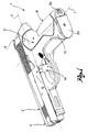
- FIG. 1 shows an axonometric view of a gun according to one embodiment of the present invention
- FIG. 1 shows the bottom portion of a butt of the gun in figure 1 , wherein the fastening of the safety cord is respectively in a lowered and raised position;
- figure 3 shows the butt of the gun in figure 1 , in separate parts
- figure 4 shows a plug of the gun in figure 1 ;
- FIG. 5 shows a fastening for a safety cord of the plug in figure 4 ;
- FIG. 6a and 6b show the fastening group formed by the plug in figure 4 and the fastening in figure 5 , respectively in a lowered and raised configuration.
- reference numeral 1 globally denotes a firearm, in particular a gun, fox example a semi-automatic gun.
- the gun 1 comprises a barrel 2 extending mainly along a main axis X, between a distal extremity 4, for the exit of the bullet, and an opposite proximal extremity 6.
- the gun 1 further comprises a butt 8, projecting from the barrel 2 and connected to it, having its main extension along a secondary axis Y, incident to the main axis X, between a connection portion 10, connected to the barrel 2, near the proximal extremity 6 of the same, and a bottom portion 12, opposite the connection portion.
- the gun further comprises a trigger 14 to fire the bullet, and a shooting mechanism, comprising for example a hammer and a firing-pin, activated by the trigger 14.
- the butt 8 internally hollow for insertion of the magazine, is closed on the bottom by a detachable closure element 20, forming part of the magazine.
- the gun 1 further comprises a fastening 30, connected to the butt 8, movable between a raised position ( figures 2c and 2d ), wherein it defines an opening 31 for fastening a safety cord, and a lowered position ( figures 2a and 2b ).
- the fastening 30 projects from the butt 8, from the bottom of the butt, closed by the closure element 20.
- the butt 8 has a main inner compartment, facing frontwards, to hold the magazine, and an auxiliary compartment, beside the main compartment, facing rearwards, accessible on the bottom of the butt 8.
- the auxiliary compartment houses a spring, normally compressed so as to constantly influence the hammer of the shooting mechanism.
- the butt 8 comprises a rear, interchangeable back-strap 8a, connected by means of a fork connection 8b element, inserted from the bottom of the butt. Further characteristics of such system are described in document EP1657519 or US2006/096147 by the Applicant.
- the gun 1 comprises a plug 50, preferably made in plastic, which can be inserted in the auxiliary compartment in the bottom of the butt.
- the spring of the hammer presses on the plug 50, remaining in compression.
- the plug 50 in the form of an element elongated along a plug axis K, coinciding with the direction of insertion of the plug in the auxiliary compartment, has a through housing 52, transversal to the plug axis K, for the insertion of a blocking pin 54.
- the blocking pin 54 is inserted through the sides of the butt, from one side to the other, to block the plug 50 in the auxiliary compartment, against the action of the spring of the hammer.
- the pin 54 is then covered by the portions of the back-strap 8a positioned along the sides of the butt 8.
- the fastening 30 is connected to the plug 50 in a movable manner, to pass from the raised position to the lowered position and vice versa.
- the plug 50 has two grooves 56a, extending along the plug axis K, that is in the direction of insertion of the plug in the butt, joined on the bottom of the plug by a slit 56b; preferably the grooves 56a are of double depth along their extension, in other words, have an internal abutment step 56c.
- the fastening 30 is, rather, the shape of a split ring.
- the fastening 30 comprises two substantially rectilinear rods 32, 34 with a main extension along the plug axis K; the rods 32, 34 are separate on one side, each terminating in a leg 36, 38, bent like an elbow towards the other, and on the other side are reciprocally joined by a base rod 39.
- the fastening 30 is engaged with the plug 50 so that the rods 32, 34 are positioned so as to slide each in its groove 56a.
- the base rod 39 is housed in the slit 56b on the bottom of the plug 50 ( figure 6a ); in the raised position rather the base rod 39 is distanced from the bottom of the plug, creating the opening 31 for the fastening of the safety cord ( figure 6b ).
- the fastening 30 is placed in the lowered position, practically hidden, in the butt; in this position the fastening does not emerge from the surface of the closure element 20 of the bottom of the butt and is therefore not an encumbrance.
- the gun according to the invention makes it possible to satisfy the requirements spoken of in that both users of civilian weapons and those of military weapons may, as needed, fasten the weapon to the safety cord.
- the production of the gun according to the invention is facilitated, it no longer being necessary to distinguish between guns for military use and guns for civilian use during the manufacturing process.
- the plug which the fastening engages with is also the abutment plug of the spring of the hammer, thereby limiting the number of components.
- the grooves are made inside the butt, in the walls delimiting the auxiliary compartment and the fastening therefore slides along the walls of the butt.
Landscapes
- Engineering & Computer Science (AREA)
- General Engineering & Computer Science (AREA)
- Toys (AREA)
Description
- The present invention relates to a firearm, in particular, a gun fitted with a fastening for a safety cord.
- It is known that for security reasons, especially in the military sphere and armed forces, most guns have a ring generally positioned at the bottom of the butt, used to fasten the safety cord, that is a sprung cord, usually in plastic material, which secures the weapon to the belt, so as to prevent it from being subtracted by third parties.
- For civilian guns however, especially for sports, there is generally no need for a safety cord.
- This leads to some difficulties.
- For example, during the manufacturing of the weapon, different procedures and different components need to be used depending on the weapon's final use.
- Some users, moreover, despite being in a civilian setting might wish to secure the weapon with a safety cord; this is not generally possible in that civilian weapons, as said, are generally lacking the fastening ring.
- The purpose of the present invention is to produce a firearm, in particular a gun, able to overcome the drawbacks of the prior art and to satisfy the needs spoken of.
- An example of a prior art solution is shown in document
US 1118331 A . - This document forms the starting point for the preamble of claim 1.
- Such purpose is achieved by a firearm according to claim 1. The dependent clams describe embodiment variations.
- Further characteristics and advantages of the firearm according to the present invention will be evident from the description below, made by way of a nonlimiting example, with reference to the attached drawings wherein:
- -
figure 1 shows an axonometric view of a gun according to one embodiment of the present invention; - -
figures 2a, 2b and 2c, 2d show the bottom portion of a butt of the gun infigure 1 , wherein the fastening of the safety cord is respectively in a lowered and raised position; - -
figure 3 shows the butt of the gun infigure 1 , in separate parts; - -
figure 4 shows a plug of the gun infigure 1 ; - -
figure 5 shows a fastening for a safety cord of the plug infigure 4 ; - -
figures 6a and 6b show the fastening group formed by the plug infigure 4 and the fastening infigure 5 , respectively in a lowered and raised configuration. - With reference to the attached figures, reference numeral 1 globally denotes a firearm, in particular a gun, fox example a semi-automatic gun.
- The gun 1 comprises a barrel 2 extending mainly along a main axis X, between a distal extremity 4, for the exit of the bullet, and an opposite proximal extremity 6.
- The gun 1 further comprises a
butt 8, projecting from the barrel 2 and connected to it, having its main extension along a secondary axis Y, incident to the main axis X, between aconnection portion 10, connected to the barrel 2, near the proximal extremity 6 of the same, and abottom portion 12, opposite the connection portion. - The gun further comprises a
trigger 14 to fire the bullet, and a shooting mechanism, comprising for example a hammer and a firing-pin, activated by thetrigger 14. - The
butt 8, internally hollow for insertion of the magazine, is closed on the bottom by adetachable closure element 20, forming part of the magazine. - The gun 1 further comprises a
fastening 30, connected to thebutt 8, movable between a raised position (figures 2c and 2d ), wherein it defines anopening 31 for fastening a safety cord, and a lowered position (figures 2a and 2b ). - Preferably, in the raised position, the fastening 30 projects from the
butt 8, from the bottom of the butt, closed by theclosure element 20. - Preferably, moreover, the
butt 8 has a main inner compartment, facing frontwards, to hold the magazine, and an auxiliary compartment, beside the main compartment, facing rearwards, accessible on the bottom of thebutt 8. - Preferably, the auxiliary compartment houses a spring, normally compressed so as to constantly influence the hammer of the shooting mechanism.
- Preferably, moreover, the
butt 8 comprises a rear, interchangeable back-strap 8a, connected by means of a fork connection 8b element, inserted from the bottom of the butt. Further characteristics of such system are described in documentEP1657519 orUS2006/096147 by the Applicant. - Moreover, the gun 1 comprises a
plug 50, preferably made in plastic, which can be inserted in the auxiliary compartment in the bottom of the butt. The spring of the hammer presses on theplug 50, remaining in compression. - The
plug 50, in the form of an element elongated along a plug axis K, coinciding with the direction of insertion of the plug in the auxiliary compartment, has a throughhousing 52, transversal to the plug axis K, for the insertion of a blockingpin 54. - Once the
plug 50 has been inserted in the auxiliary compartment and the spring of the hammer thus placed in compression, the blockingpin 54 is inserted through the sides of the butt, from one side to the other, to block theplug 50 in the auxiliary compartment, against the action of the spring of the hammer. - Preferably, the
pin 54 is then covered by the portions of the back-strap 8a positioned along the sides of thebutt 8. - The
fastening 30 is connected to theplug 50 in a movable manner, to pass from the raised position to the lowered position and vice versa. - For example, the
plug 50 has twogrooves 56a, extending along the plug axis K, that is in the direction of insertion of the plug in the butt, joined on the bottom of the plug by aslit 56b; preferably thegrooves 56a are of double depth along their extension, in other words, have aninternal abutment step 56c. - The
fastening 30 is, rather, the shape of a split ring. - For example, the
fastening 30 comprises two substantiallyrectilinear rods rods leg base rod 39. - The
fastening 30 is engaged with theplug 50 so that therods groove 56a. - In the lowered position of the
fastening 30, thebase rod 39 is housed in theslit 56b on the bottom of the plug 50 (figure 6a ); in the raised position rather thebase rod 39 is distanced from the bottom of the plug, creating theopening 31 for the fastening of the safety cord (figure 6b ). - In the raised limit position, the
legs step 56c of thegroove 56a, thereby preventing the detachment of thefastening 30 from the butt. - During normal use of the gun according to the invention, when the user does not wish to fasten the gun to the safety cord, the
fastening 30 is placed in the lowered position, practically hidden, in the butt; in this position the fastening does not emerge from the surface of theclosure element 20 of the bottom of the butt and is therefore not an encumbrance. - When the user so wishes or is obliged to use the safety cord, all that is required is to place the fastening 30 in the raised position, forming the
opening 31 for the fastening of the safety cord. - Innovatively, the gun according to the invention makes it possible to satisfy the requirements spoken of in that both users of civilian weapons and those of military weapons may, as needed, fasten the weapon to the safety cord.
- Advantageously, moreover, the production of the gun according to the invention is facilitated, it no longer being necessary to distinguish between guns for military use and guns for civilian use during the manufacturing process.
- According to a further advantageous aspect, when the fastening is not used, it does not inconvenience the gun user in that it substantially disappears flush with the surface of the closure element of the butt.
- According to yet a further advantageous aspect the plug which the fastening engages with is also the abutment plug of the spring of the hammer, thereby limiting the number of components.
- It is clear that a person skilled in the art may make modifications to the gun described above.
- According to a further variation (not shown) , the grooves are made inside the butt, in the walls delimiting the auxiliary compartment and the fastening therefore slides along the walls of the butt.
Claims (9)
- Gun (1) comprising a barrel (2), a butt (8) connected to the barrel (2), a plug (50) inserted in the butt (8), a hammer and a spring which constantly influences the hammer, and a fastening (30) to fasten a safety cord, wherein the spring of the hammer presses on said plug (50), and wherein said fastening (30) is connected to the plug (50) in a movable manner, said fastening being movable between a lowered position and a raised position wherein it defines an accessible opening (31) for the fastening of the safety cord, characterized by the fact that the fastening (30) slides on the plug (50) in a sliding direction (K).
- Gun according to claim 1, wherein the fastening (30) is connected to the butt (8) and defines the opening (31) with said butt.
- Gun according to claim 2, wherein the fastening (30) is connected to the bottom of the butt (8).
- Gun according to claim 1, wherein the butt (8) has an auxiliary compartment accessible from the bottom, said plug (50) being inserted in the auxiliary compartment, so that the fastening (30) is accessible from the outside.
- Gun according to claim 1, wherein the plug (50) comprises grooves (56a) parallel to the sliding direction, and the fastening (30) comprises rectilinear rods (32, 34) sliding in said grooves.
- Gun according to claim 5, wherein the grooves (56a) each comprise an abutment step (56c) to form an abutment of the fastening (30) in the limit raised position.
- Gun according to claim 6, wherein the fastening (30) comprises a base rod (39) housed in a slit (56b) of the plug (50) in the limit lowered position.
- Gun according to any of the preceding claims, wherein the plug (50) comprises a transversal compartment (52) for the insertion of a transversal blocking pin (54).
- Gun according to any of the claims from 1 to 3, wherein the fastening (30) is movable in grooves made inside the butt, along the walls of said butt.
Applications Claiming Priority (1)
| Application Number | Priority Date | Filing Date | Title |
|---|---|---|---|
| IT000225A ITBS20090225A1 (en) | 2009-12-16 | 2009-12-16 | PISTOL WITH HOOK FOR CORREGOLO |
Publications (2)
| Publication Number | Publication Date |
|---|---|
| EP2336708A1 EP2336708A1 (en) | 2011-06-22 |
| EP2336708B1 true EP2336708B1 (en) | 2013-01-16 |
Family
ID=42289079
Family Applications (1)
| Application Number | Title | Priority Date | Filing Date |
|---|---|---|---|
| EP10190704A Active EP2336708B1 (en) | 2009-12-16 | 2010-11-10 | Gun with fastening for safety cord |
Country Status (3)
| Country | Link |
|---|---|
| US (1) | US8438772B2 (en) |
| EP (1) | EP2336708B1 (en) |
| IT (1) | ITBS20090225A1 (en) |
Families Citing this family (6)
| Publication number | Priority date | Publication date | Assignee | Title |
|---|---|---|---|---|
| ITBS20090225A1 (en) * | 2009-12-16 | 2011-06-17 | Beretta Armi Spa | PISTOL WITH HOOK FOR CORREGOLO |
| US9057574B2 (en) | 2012-06-14 | 2015-06-16 | Ra Brands, L.L.C. | Thumb safety for model 1911 handgun |
| US10809025B2 (en) * | 2017-08-16 | 2020-10-20 | Zrodelta, Llc | Pistol |
| US10809036B2 (en) | 2017-08-16 | 2020-10-20 | Zrodelta, Llc | Pistol |
| TR2022009034A1 (en) * | 2022-06-01 | 2023-12-21 | Samsun Yurt Savunma Sanayi Ve Ticaret Anonim Sirketi | PISTOL PISTOL DESIGN WITH INSERT PRODUCED AS A ONE-PIECE THROUGH INJECTION |
| TR2023002951A2 (en) * | 2023-03-16 | 2023-05-22 | Cakir Said Yusuf | A GRIP DEVICE |
Citations (1)
| Publication number | Priority date | Publication date | Assignee | Title |
|---|---|---|---|---|
| US1118331A (en) * | 1914-04-04 | 1914-11-24 | John Howard Carl | Automatic firearm. |
Family Cites Families (27)
| Publication number | Priority date | Publication date | Assignee | Title |
|---|---|---|---|---|
| US891748A (en) * | 1906-03-19 | 1908-06-23 | Joseph Tambour | Safety locking device for small-arms. |
| US875469A (en) * | 1906-10-08 | 1907-12-31 | Joseph Tambour | Automatic safety appliance for locking the hammer and the sear of small-arms. |
| US905020A (en) * | 1908-04-23 | 1908-11-24 | Joseph Tambour | Safety-lock for revolvers, pistols, or the like. |
| DE342319C (en) * | 1920-09-21 | 1921-10-15 | Paul Becker | Carrying device on self-loading pistols, etc. |
| US2115041A (en) * | 1934-02-08 | 1938-04-26 | Obregon Alejandro | Automatic loading firearm |
| US2945316A (en) * | 1958-05-09 | 1960-07-19 | Harrington & Richardson Inc | Safety lock for firearms |
| IT1103524B (en) * | 1978-02-24 | 1985-10-14 | Beretta Armi Spa | SAFETY DEVICE FOR GUNS WITH AUTOMATIC DOG RELEASE |
| US4593487A (en) * | 1985-03-27 | 1986-06-10 | Sturm, Ruger & Company, Inc. | Latch arrangement for pistol spring strut |
| US4685237A (en) * | 1986-08-19 | 1987-08-11 | Hugg Clifford R | Retractable swivel stud |
| US4672763A (en) * | 1986-08-21 | 1987-06-16 | Cunningham Jerry M | Safety device for preventing the unauthorized firing of a weapon by releasing the hammer spring |
| US4845870A (en) * | 1987-09-03 | 1989-07-11 | Vernon Terry M | Firearm disabling apparatus |
| US4967502A (en) * | 1987-09-03 | 1990-11-06 | Vernon Terry M | Firearm disabling apparatus |
| US4833811A (en) * | 1988-07-07 | 1989-05-30 | Earl Wilkinson | Safety for pistols |
| US5323940A (en) * | 1992-07-14 | 1994-06-28 | Hart Milton M | Fall-away gun sling attachment |
| US5361525A (en) * | 1993-12-27 | 1994-11-08 | Bowes Kenneth E | Gun safety lock |
| US5692654A (en) * | 1996-08-23 | 1997-12-02 | Bell; Dennis L. | Sling and accessory attachment system |
| US6178600B1 (en) * | 1998-01-16 | 2001-01-30 | Michaels Of Oregon Co. | Molded plastic swivel connector |
| ITBS20010001A1 (en) * | 2001-01-11 | 2002-07-11 | Beretta Armi Spa | SAFETY DEVICE FOR PISTOLS |
| AT412125B (en) * | 2003-01-31 | 2004-09-27 | Glock Gaston | LOCKING DEVICE FOR A GUN |
| ITMI20042166A1 (en) | 2004-11-11 | 2005-02-11 | Beretta Armi Spa | HANDLE OF FIREARMS IN PARTICULAR PISTOL |
| ITMI20042167A1 (en) * | 2004-11-11 | 2005-02-11 | Beretta Armi Spa | GUN AND METHOD TO ASSEMBLE A GUN |
| ITMI20042449A1 (en) * | 2004-12-22 | 2005-03-22 | Beretta Armi Spa | GUN WITH INTERCHANGEABLE CHEEK |
| US20070045363A1 (en) * | 2005-08-25 | 2007-03-01 | Mc Clellan W T | Handgun carrier |
| US7752797B1 (en) * | 2006-02-08 | 2010-07-13 | Swan Richard E | Sling swivel with integrated screwdriver |
| US7716864B2 (en) * | 2007-01-10 | 2010-05-18 | Smith & Wesson Corp. | Molded rifle stock |
| US20100199541A1 (en) * | 2009-02-09 | 2010-08-12 | Vest Timothy J | Sling swivel |
| ITBS20090225A1 (en) * | 2009-12-16 | 2011-06-17 | Beretta Armi Spa | PISTOL WITH HOOK FOR CORREGOLO |
-
2009
- 2009-12-16 IT IT000225A patent/ITBS20090225A1/en unknown
-
2010
- 2010-11-10 EP EP10190704A patent/EP2336708B1/en active Active
- 2010-12-03 US US12/959,908 patent/US8438772B2/en not_active Expired - Fee Related
Patent Citations (1)
| Publication number | Priority date | Publication date | Assignee | Title |
|---|---|---|---|---|
| US1118331A (en) * | 1914-04-04 | 1914-11-24 | John Howard Carl | Automatic firearm. |
Also Published As
| Publication number | Publication date |
|---|---|
| EP2336708A1 (en) | 2011-06-22 |
| ITBS20090225A1 (en) | 2011-06-17 |
| US20120005933A1 (en) | 2012-01-12 |
| US8438772B2 (en) | 2013-05-14 |
Similar Documents
| Publication | Publication Date | Title |
|---|---|---|
| US10197353B2 (en) | Receiver with an ambidextrous bolt stop | |
| US8371056B1 (en) | Firearm accessory rail adaptor bracket | |
| US9714804B2 (en) | Firearm with safe axis firing pin and center aligned barrel | |
| US9194635B1 (en) | Weapon conversion kit | |
| EP2336708A1 (en) | Gun with fastening for safety cord | |
| US8819975B2 (en) | Rifle and kit for making same | |
| US9797666B2 (en) | Convertible lower receiver | |
| US7735409B1 (en) | Conversion kit and method for a RUGER® 10/22® semi-automatic .22 caliber rim fire gun to shoot .17 mach 2 cartridges | |
| US8333028B1 (en) | Firearm mode selection mechanism | |
| US10260828B2 (en) | Receiver assembly for locked breech pistol | |
| US20140237877A1 (en) | Combination safety round and multi-tool | |
| US20170241729A1 (en) | Bolt Catch for a Rifle | |
| US9310148B2 (en) | Apparatus and method requiring disassembly of rifle to remove magazine | |
| US20160010936A1 (en) | Firearm Compensator Assembly | |
| GB2094451A (en) | Self-loading firearm | |
| EP0525309A1 (en) | Bolt repositioning device for firearms | |
| US20180372437A1 (en) | Firearm insert | |
| US20180080731A1 (en) | Firearms Trigger Assembly | |
| WO2005108901A3 (en) | Semiautomatic handgun | |
| ITBS20130170A1 (en) | FIRE WEAPON DRIVE WITH THUMB | |
| US10684085B2 (en) | Quick release gas block securing system | |
| US20060156608A1 (en) | Pistol | |
| US20120055059A1 (en) | Butt stock conversion kit | |
| WO2018023076A1 (en) | Dual firearm gunstock holstering | |
| WO2018102458A2 (en) | Semi-automatic pistol |
Legal Events
| Date | Code | Title | Description |
|---|---|---|---|
| PUAI | Public reference made under article 153(3) epc to a published international application that has entered the european phase |
Free format text: ORIGINAL CODE: 0009012 |
|
| AK | Designated contracting states |
Kind code of ref document: A1 Designated state(s): AL AT BE BG CH CY CZ DE DK EE ES FI FR GB GR HR HU IE IS IT LI LT LU LV MC MK MT NL NO PL PT RO RS SE SI SK SM TR |
|
| AX | Request for extension of the european patent |
Extension state: BA ME |
|
| 17P | Request for examination filed |
Effective date: 20111222 |
|
| GRAP | Despatch of communication of intention to grant a patent |
Free format text: ORIGINAL CODE: EPIDOSNIGR1 |
|
| GRAS | Grant fee paid |
Free format text: ORIGINAL CODE: EPIDOSNIGR3 |
|
| GRAA | (expected) grant |
Free format text: ORIGINAL CODE: 0009210 |
|
| AK | Designated contracting states |
Kind code of ref document: B1 Designated state(s): AL AT BE BG CH CY CZ DE DK EE ES FI FR GB GR HR HU IE IS IT LI LT LU LV MC MK MT NL NO PL PT RO RS SE SI SK SM TR |
|
| REG | Reference to a national code |
Ref country code: GB Ref legal event code: FG4D |
|
| REG | Reference to a national code |
Ref country code: CH Ref legal event code: EP |
|
| REG | Reference to a national code |
Ref country code: IE Ref legal event code: FG4D |
|
| REG | Reference to a national code |
Ref country code: AT Ref legal event code: REF Ref document number: 594103 Country of ref document: AT Kind code of ref document: T Effective date: 20130215 Ref country code: CH Ref legal event code: EP |
|
| REG | Reference to a national code |
Ref country code: DE Ref legal event code: R096 Ref document number: 602010004613 Country of ref document: DE Effective date: 20130314 |
|
| REG | Reference to a national code |
Ref country code: NL Ref legal event code: VDEP Effective date: 20130116 |
|
| REG | Reference to a national code |
Ref country code: LT Ref legal event code: MG4D |
|
| PG25 | Lapsed in a contracting state [announced via postgrant information from national office to epo] |
Ref country code: LT Free format text: LAPSE BECAUSE OF FAILURE TO SUBMIT A TRANSLATION OF THE DESCRIPTION OR TO PAY THE FEE WITHIN THE PRESCRIBED TIME-LIMIT Effective date: 20130116 Ref country code: NO Free format text: LAPSE BECAUSE OF FAILURE TO SUBMIT A TRANSLATION OF THE DESCRIPTION OR TO PAY THE FEE WITHIN THE PRESCRIBED TIME-LIMIT Effective date: 20130416 Ref country code: IS Free format text: LAPSE BECAUSE OF FAILURE TO SUBMIT A TRANSLATION OF THE DESCRIPTION OR TO PAY THE FEE WITHIN THE PRESCRIBED TIME-LIMIT Effective date: 20130516 Ref country code: ES Free format text: LAPSE BECAUSE OF FAILURE TO SUBMIT A TRANSLATION OF THE DESCRIPTION OR TO PAY THE FEE WITHIN THE PRESCRIBED TIME-LIMIT Effective date: 20130427 Ref country code: SE Free format text: LAPSE BECAUSE OF FAILURE TO SUBMIT A TRANSLATION OF THE DESCRIPTION OR TO PAY THE FEE WITHIN THE PRESCRIBED TIME-LIMIT Effective date: 20130116 Ref country code: BG Free format text: LAPSE BECAUSE OF FAILURE TO SUBMIT A TRANSLATION OF THE DESCRIPTION OR TO PAY THE FEE WITHIN THE PRESCRIBED TIME-LIMIT Effective date: 20130416 |
|
| PG25 | Lapsed in a contracting state [announced via postgrant information from national office to epo] |
Ref country code: SI Free format text: LAPSE BECAUSE OF FAILURE TO SUBMIT A TRANSLATION OF THE DESCRIPTION OR TO PAY THE FEE WITHIN THE PRESCRIBED TIME-LIMIT Effective date: 20130116 Ref country code: PT Free format text: LAPSE BECAUSE OF FAILURE TO SUBMIT A TRANSLATION OF THE DESCRIPTION OR TO PAY THE FEE WITHIN THE PRESCRIBED TIME-LIMIT Effective date: 20130516 Ref country code: LV Free format text: LAPSE BECAUSE OF FAILURE TO SUBMIT A TRANSLATION OF THE DESCRIPTION OR TO PAY THE FEE WITHIN THE PRESCRIBED TIME-LIMIT Effective date: 20130116 Ref country code: FI Free format text: LAPSE BECAUSE OF FAILURE TO SUBMIT A TRANSLATION OF THE DESCRIPTION OR TO PAY THE FEE WITHIN THE PRESCRIBED TIME-LIMIT Effective date: 20130116 Ref country code: NL Free format text: LAPSE BECAUSE OF FAILURE TO SUBMIT A TRANSLATION OF THE DESCRIPTION OR TO PAY THE FEE WITHIN THE PRESCRIBED TIME-LIMIT Effective date: 20130116 Ref country code: PL Free format text: LAPSE BECAUSE OF FAILURE TO SUBMIT A TRANSLATION OF THE DESCRIPTION OR TO PAY THE FEE WITHIN THE PRESCRIBED TIME-LIMIT Effective date: 20130116 Ref country code: GR Free format text: LAPSE BECAUSE OF FAILURE TO SUBMIT A TRANSLATION OF THE DESCRIPTION OR TO PAY THE FEE WITHIN THE PRESCRIBED TIME-LIMIT Effective date: 20130417 |
|
| PG25 | Lapsed in a contracting state [announced via postgrant information from national office to epo] |
Ref country code: HR Free format text: LAPSE BECAUSE OF FAILURE TO SUBMIT A TRANSLATION OF THE DESCRIPTION OR TO PAY THE FEE WITHIN THE PRESCRIBED TIME-LIMIT Effective date: 20130116 Ref country code: RS Free format text: LAPSE BECAUSE OF FAILURE TO SUBMIT A TRANSLATION OF THE DESCRIPTION OR TO PAY THE FEE WITHIN THE PRESCRIBED TIME-LIMIT Effective date: 20130116 |
|
| PG25 | Lapsed in a contracting state [announced via postgrant information from national office to epo] |
Ref country code: EE Free format text: LAPSE BECAUSE OF FAILURE TO SUBMIT A TRANSLATION OF THE DESCRIPTION OR TO PAY THE FEE WITHIN THE PRESCRIBED TIME-LIMIT Effective date: 20130116 Ref country code: SK Free format text: LAPSE BECAUSE OF FAILURE TO SUBMIT A TRANSLATION OF THE DESCRIPTION OR TO PAY THE FEE WITHIN THE PRESCRIBED TIME-LIMIT Effective date: 20130116 Ref country code: CZ Free format text: LAPSE BECAUSE OF FAILURE TO SUBMIT A TRANSLATION OF THE DESCRIPTION OR TO PAY THE FEE WITHIN THE PRESCRIBED TIME-LIMIT Effective date: 20130116 Ref country code: RO Free format text: LAPSE BECAUSE OF FAILURE TO SUBMIT A TRANSLATION OF THE DESCRIPTION OR TO PAY THE FEE WITHIN THE PRESCRIBED TIME-LIMIT Effective date: 20130116 Ref country code: DK Free format text: LAPSE BECAUSE OF FAILURE TO SUBMIT A TRANSLATION OF THE DESCRIPTION OR TO PAY THE FEE WITHIN THE PRESCRIBED TIME-LIMIT Effective date: 20130116 |
|
| PLBE | No opposition filed within time limit |
Free format text: ORIGINAL CODE: 0009261 |
|
| STAA | Information on the status of an ep patent application or granted ep patent |
Free format text: STATUS: NO OPPOSITION FILED WITHIN TIME LIMIT |
|
| PG25 | Lapsed in a contracting state [announced via postgrant information from national office to epo] |
Ref country code: CY Free format text: LAPSE BECAUSE OF FAILURE TO SUBMIT A TRANSLATION OF THE DESCRIPTION OR TO PAY THE FEE WITHIN THE PRESCRIBED TIME-LIMIT Effective date: 20130116 |
|
| 26N | No opposition filed |
Effective date: 20131017 |
|
| REG | Reference to a national code |
Ref country code: DE Ref legal event code: R097 Ref document number: 602010004613 Country of ref document: DE Effective date: 20131017 |
|
| PG25 | Lapsed in a contracting state [announced via postgrant information from national office to epo] |
Ref country code: MC Free format text: LAPSE BECAUSE OF FAILURE TO SUBMIT A TRANSLATION OF THE DESCRIPTION OR TO PAY THE FEE WITHIN THE PRESCRIBED TIME-LIMIT Effective date: 20130116 |
|
| REG | Reference to a national code |
Ref country code: FR Ref legal event code: ST Effective date: 20140731 |
|
| REG | Reference to a national code |
Ref country code: IE Ref legal event code: MM4A |
|
| PG25 | Lapsed in a contracting state [announced via postgrant information from national office to epo] |
Ref country code: IE Free format text: LAPSE BECAUSE OF NON-PAYMENT OF DUE FEES Effective date: 20131110 |
|
| PG25 | Lapsed in a contracting state [announced via postgrant information from national office to epo] |
Ref country code: FR Free format text: LAPSE BECAUSE OF NON-PAYMENT OF DUE FEES Effective date: 20131202 |
|
| PG25 | Lapsed in a contracting state [announced via postgrant information from national office to epo] |
Ref country code: SM Free format text: LAPSE BECAUSE OF FAILURE TO SUBMIT A TRANSLATION OF THE DESCRIPTION OR TO PAY THE FEE WITHIN THE PRESCRIBED TIME-LIMIT Effective date: 20130116 |
|
| PG25 | Lapsed in a contracting state [announced via postgrant information from national office to epo] |
Ref country code: TR Free format text: LAPSE BECAUSE OF FAILURE TO SUBMIT A TRANSLATION OF THE DESCRIPTION OR TO PAY THE FEE WITHIN THE PRESCRIBED TIME-LIMIT Effective date: 20130116 |
|
| REG | Reference to a national code |
Ref country code: CH Ref legal event code: PL |
|
| GBPC | Gb: european patent ceased through non-payment of renewal fee |
Effective date: 20141110 |
|
| PG25 | Lapsed in a contracting state [announced via postgrant information from national office to epo] |
Ref country code: HU Free format text: LAPSE BECAUSE OF FAILURE TO SUBMIT A TRANSLATION OF THE DESCRIPTION OR TO PAY THE FEE WITHIN THE PRESCRIBED TIME-LIMIT; INVALID AB INITIO Effective date: 20101110 Ref country code: MK Free format text: LAPSE BECAUSE OF FAILURE TO SUBMIT A TRANSLATION OF THE DESCRIPTION OR TO PAY THE FEE WITHIN THE PRESCRIBED TIME-LIMIT Effective date: 20130116 Ref country code: CH Free format text: LAPSE BECAUSE OF NON-PAYMENT OF DUE FEES Effective date: 20141130 Ref country code: LU Free format text: LAPSE BECAUSE OF NON-PAYMENT OF DUE FEES Effective date: 20131110 Ref country code: LI Free format text: LAPSE BECAUSE OF NON-PAYMENT OF DUE FEES Effective date: 20141130 |
|
| PG25 | Lapsed in a contracting state [announced via postgrant information from national office to epo] |
Ref country code: MT Free format text: LAPSE BECAUSE OF FAILURE TO SUBMIT A TRANSLATION OF THE DESCRIPTION OR TO PAY THE FEE WITHIN THE PRESCRIBED TIME-LIMIT Effective date: 20130116 |
|
| PG25 | Lapsed in a contracting state [announced via postgrant information from national office to epo] |
Ref country code: GB Free format text: LAPSE BECAUSE OF NON-PAYMENT OF DUE FEES Effective date: 20141110 |
|
| PG25 | Lapsed in a contracting state [announced via postgrant information from national office to epo] |
Ref country code: AL Free format text: LAPSE BECAUSE OF FAILURE TO SUBMIT A TRANSLATION OF THE DESCRIPTION OR TO PAY THE FEE WITHIN THE PRESCRIBED TIME-LIMIT Effective date: 20130116 |
|
| P01 | Opt-out of the competence of the unified patent court (upc) registered |
Effective date: 20230522 |
|
| PGFP | Annual fee paid to national office [announced via postgrant information from national office to epo] |
Ref country code: DE Payment date: 20241125 Year of fee payment: 15 |
|
| PGFP | Annual fee paid to national office [announced via postgrant information from national office to epo] |
Ref country code: BE Payment date: 20241120 Year of fee payment: 15 |
|
| PGFP | Annual fee paid to national office [announced via postgrant information from national office to epo] |
Ref country code: AT Payment date: 20241119 Year of fee payment: 15 |
|
| PGFP | Annual fee paid to national office [announced via postgrant information from national office to epo] |
Ref country code: IT Payment date: 20250926 Year of fee payment: 16 |