EP2336588A2 - Coupling actuation system - Google Patents
Coupling actuation system Download PDFInfo
- Publication number
- EP2336588A2 EP2336588A2 EP10015558A EP10015558A EP2336588A2 EP 2336588 A2 EP2336588 A2 EP 2336588A2 EP 10015558 A EP10015558 A EP 10015558A EP 10015558 A EP10015558 A EP 10015558A EP 2336588 A2 EP2336588 A2 EP 2336588A2
- Authority
- EP
- European Patent Office
- Prior art keywords
- bearing
- ring
- coupling system
- carrier
- force
- Prior art date
- Legal status (The legal status is an assumption and is not a legal conclusion. Google has not performed a legal analysis and makes no representation as to the accuracy of the status listed.)
- Granted
Links
Images


Classifications
-
- F—MECHANICAL ENGINEERING; LIGHTING; HEATING; WEAPONS; BLASTING
- F16—ENGINEERING ELEMENTS AND UNITS; GENERAL MEASURES FOR PRODUCING AND MAINTAINING EFFECTIVE FUNCTIONING OF MACHINES OR INSTALLATIONS; THERMAL INSULATION IN GENERAL
- F16D—COUPLINGS FOR TRANSMITTING ROTATION; CLUTCHES; BRAKES
- F16D23/00—Details of mechanically-actuated clutches not specific for one distinct type
- F16D23/12—Mechanical clutch-actuating mechanisms arranged outside the clutch as such
- F16D23/14—Clutch-actuating sleeves or bearings; Actuating members directly connected to clutch-actuating sleeves or bearings
Definitions
- the invention relates to a clutch actuation system which has an actuating device which has means for introducing force to a bearing.
- Bearings in particular release bearings, which can be actuated with a clutch actuation system in the form of a concentric slave cylinder (CSC), are used in hydraulic clutch systems in the functional chain between clutch pedal and clutch.
- the bearing has a bearing ring, in which the force of the Primaaus Wegers when it is actuated via a bearing carrier can be introduced.
- the object of the invention is to provide a clutch actuation system, which ensures a homogeneous or even load application in a bearing, which is particularly exposed to a 2-point force application and thus increases the life of the bearing.
- the clutch actuation system which has an actuating device which has a bearing carrier for introducing force onto a bearing ring of a bearing unit, according to the invention has an operative connection between the bearing carrier and the bearing ring of the bearing unit on, which converts a substantially punctiform introduction of force from the direction of the actuator in a uniform force on the bearing unit.
- the bearing carrier and / or the bearing ring and / or an intermediate element arranged between the bearing carrier and the bearing ring are designed, at least in some areas, to be elastically deformable in such a way that, in spite of the punctiform impingement, a uniform application of force to the bearing unit takes place.
- the bearing ring in particular the bearing outer ring, in the direction of the bearing carrier on a contact region which is inclined radially outwardly at an angle ⁇ , so as to ensure that the contact area can deform elastically, if an axial force on this acts.
- the contact surface of the bearing carrier and the contact area of the bearing outer ring are thus not (as is usual conventionally) flat against one another.
- This effect can be increased by the fact that the bearing area of the bearing outer ring set up at an angle ⁇ is slotted. Radial slots are preferably introduced into the contact area of the bearing outer ring. These slots allow the bearing outer ring (the abutment area) to adapt more flexibly to the load. The efficacy was demonstrated by means of an FEM study.
- the intermediate element is arranged between bearing outer ring and bearing carrier and preferably in the form of a corresponding corrugated spring or a steel disc.
- the sinusoidal contour adapts continuously until an almost flat surface is reached in the design load case (maximum load, preferably main load).
- the surface must not be completely flat and, especially in the area of the load introduction by the lever tips under load, not rest flat on the bearing carrier, as otherwise a stiff connection would be made, whereby the elastic effect of the system would be lost.
- care must be taken that it is secured against rotation.
- the use of a spring depends on the applied force. The spring must be designed so that the maximum force, which is applied to the clutch system is less than the force of the spring, otherwise it would lay flat.
- a third variant of the design of the coupling system is that the bearing carrier is partially weakened in the load introduction so that less rigid areas alternate with stiffer areas, whereby more load is introduced into the stiffer areas of the bearing carrier.
- the bearing carrier may be partially weakened in the region of its contact surface to the bearing unit and having recesses in the contact surface, wherein preferably in each recess one or more plastic elements are used, which may have openings to enhance the effect. This also achieves the desired stiffness difference.
- the clutch actuating system as shown in FIGS. 1, 2 . 4, 5 and 10 a Gottausschreiber on, of which only the bearing carrier 1 is shown here, which acts on actuation of the Gottausschreibers on a bearing unit in the form of a release bearing 2.
- the release bearing 2 has a subsequent to the bearing support 1 bearing outer ring 3 and a bearing inner ring 4, between which rolling elements 5 are located.
- FIG. 1 has the bearing outer ring 3 in the direction of the bearing carrier 1 at an angle ⁇ inclined contact area 3.1, whereby a certain elasticity is ensured by a homogeneous force is applied to the bearing during its operation by the bearing bracket 1. In the range of high axial forces on the bearing outer ring 3, this can thereby deform slightly more elastic, while maintaining its shape at a low load.
- FIGS. 4 and 5 a release bearing 2 and a bearing support 1 are shown, between which an intermediate element in the form of a steel disc 6 is arranged with a sinusoidal contour, wherein FIG. 4 and FIG. 5 offset by 90 ° to each other.
- the steel disc 6 is to illustrate the sinusoidal contour, which achieves an axial spring action is in FIG. 6 in the side view and in FIG. 7 shown in three-dimensional view.
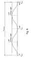
- FIG. 8 The schematic diagram of the diagram of the load application over the circumference U bearing carrier of the bearing carrier when using a steel disc according to FIGS. 6 and 7 or in a sinusoidal design of the contact surface of the bearing carrier is in FIG. 8 shown.
- the load F lever is applied to the bearing via the lifting tips at 0 °, 180 ° and 360 ° and the bearing is in contact with the steel disc or the sinusoidal contour of the bearing bracket at 90 ° and 270 °
- the sine contour continuously adapts until a nearly flat surface is reached.
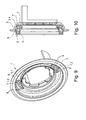
- FIG. 9 shows the three-dimensional detail of the bearing support 1 and FIG. 10 the combination of the bearing carrier 1 according to FIG. 9 with a bearing unit in the form of a release bearing 2 in longitudinal section.
- the bearing support 1 is partially weakened in the region of its contact surface 1.1 to the bearing unit (release bearing 2) and has to recesses 1.2 in the contact surface 1.1, were used in the plastic elements 7, which are provided with apertures 8.
- less rigid areas alternate with stiffer areas.
- By inserting the weaker material in the form of plastic elements 7 more load is introduced into the stiffer areas of the bearing support 1, whereby a more homogeneous load distribution is achieved.
Landscapes
- Engineering & Computer Science (AREA)
- General Engineering & Computer Science (AREA)
- Mechanical Engineering (AREA)
- Mechanical Operated Clutches (AREA)
Abstract
Description
Die Erfindung betrifft ein Kupplungsbetätigungssystem, welches eine Betätigungseinrichtung aufweist, die Mittel zur Krafteinleitung auf ein Lager besitzt.The invention relates to a clutch actuation system which has an actuating device which has means for introducing force to a bearing.
Lager, insbesondere Ausrücklager, die mit einem Kupplungsbetätigungssystem in Form eines Zentralausrückers ("Concentric Slave Cylinder" ― CSC) betätigbar sind, werden bei hydraulischen Kupplungssystemen in der Funktionskette zwischen Kupplungspedal und Kupplung eingesetzt. Das Lager besitzt dabei einen Lagerring, in welchem die Kraft des Zentralausrückers bei dessen Betätigung über einen Lagerträger einleitbar ist.Bearings, in particular release bearings, which can be actuated with a clutch actuation system in the form of a concentric slave cylinder (CSC), are used in hydraulic clutch systems in the functional chain between clutch pedal and clutch. The bearing has a bearing ring, in which the force of the Zentralausrückers when it is actuated via a bearing carrier can be introduced.
Aus der Druckschrift
Die Aufgabe der Erfindung besteht darin, ein Kupplungsbetätigungssystem zu schaffen, welches bei einem Lager, das insbesondere einer 2-Punkt-Kraftbeaufschlagung ausgesetzt ist, eine homogene bzw. gleichmäßige Lastaufbringung gewährleistet und somit die Lebensdauer des Lagers erhöht.The object of the invention is to provide a clutch actuation system, which ensures a homogeneous or even load application in a bearing, which is particularly exposed to a 2-point force application and thus increases the life of the bearing.
Diese Aufgabe wird mit den Merkmalen des ersten Patentanspruchs gelöst. Vorteilhafte Ausgestaltungen ergeben sich aus den Unteransprüchen.This object is achieved with the features of the first claim. Advantageous embodiments emerge from the subclaims.
Das Kupplungsbetätigungssystem, welches eine Betätigungseinrichtung aufweist, die einen Lagerträger zur Krafteinleitung auf einen Lagerring einer Lagereinheit besitzt, weist erfindungsgemäß zwischen dem Lagerträger und dem Lagerring der Lagereinheit eine Wirkverbindung auf, die eine im Wesentlichen punktförmige Krafteinleitung aus Richtung der Betätigungseinrichtung in eine gleichmäßige Krafteinleitung auf die Lagereinheit umwandelt.The clutch actuation system, which has an actuating device which has a bearing carrier for introducing force onto a bearing ring of a bearing unit, according to the invention has an operative connection between the bearing carrier and the bearing ring of the bearing unit on, which converts a substantially punctiform introduction of force from the direction of the actuator in a uniform force on the bearing unit.
Dadurch wird eine gleichmäßige Kraftverteilung auf den Lagerring und somit die Lagereinheit des CSC sichergestellt, wodurch gewährleistet ist, dass die Kugeln des Lagers gleichmäßig belastet werden, was zur Erhöhung der Lebensdauer des Lagers beiträgt.As a result, a uniform force distribution is ensured on the bearing ring and thus the bearing unit of the CSC, which ensures that the balls of the bearing are uniformly loaded, which contributes to increasing the life of the bearing.
Dazu werden der Lagerträger und/oder der Lagerring und/oder ein zwischen Lagerträger und Lagerring angeordnetes Zwischenelement, zumindest bereichsweise, derart elastisch verformbar ausgelegt, dass trotz der punktförmigen Beaufschlagung eine gleichmäßige Krafteinleitung auf die Lagereinheit erfolgt.For this purpose, the bearing carrier and / or the bearing ring and / or an intermediate element arranged between the bearing carrier and the bearing ring are designed, at least in some areas, to be elastically deformable in such a way that, in spite of the punctiform impingement, a uniform application of force to the bearing unit takes place.
Dies kann durch verschiedene konstruktive Maßnahmen erfolgen.This can be done by various design measures.
In einer ersten Variante weist der Lagerring, insbesondere der Lageraußenring, in Richtung zum Lagerträger einen Anlagebereich auf, der radial nach außen in einem Winkel α geneigt ist, so dass gewährleistet wird, dass sich der Anlagebereich elastisch verformen kann, wenn auf diesen eine axiale Kraft wirkt. Die Anlagefläche des Lagerträgers und der Anlagebereich des Lageraußenringes liegen somit nicht (wie herkömmlich üblich) flächig aneinander an.In a first variant, the bearing ring, in particular the bearing outer ring, in the direction of the bearing carrier on a contact region which is inclined radially outwardly at an angle α, so as to ensure that the contact area can deform elastically, if an axial force on this acts. The contact surface of the bearing carrier and the contact area of the bearing outer ring are thus not (as is usual conventionally) flat against one another.
Durch diesen im Winkel α aufgestellten Lageraußenring wird dieser als elastisches Element in das System aufgenommen. Dadurch wird die Last über dessen im Winkel α aufgestellten Anlagebereich in das Lager eingebracht. Im Bereich hoher Axialkräfte am Lageraußenring kann sich dieser durch die Neigung des Anlagebereiches im Winkel α etwas mehr elastisch verformen, während er bei einer geringen Last seine Form beibehält.By this set at an angle α bearing outer ring this is added as an elastic element in the system. As a result, the load is introduced into the bearing via its contact area set up at an angle α. In the area of high axial forces on the bearing outer ring, this can deform somewhat more elastically due to the inclination of the contact area at an angle α, while retaining its shape at a low load.
Dieser Effekt kann dadurch erhöht werden, dass der im Winkel α aufgestellte Anlagebereich des Lageraußenringes geschlitzt ausgeführt wird. Vorzugsweise werden radiale Schlitze in den Anlagebereich des Lageraußenringes eingebracht. Diese Schlitze ermöglichen dem Lageraußenring (dem Anlagebereich), sich flexibler an die Last anzupassen. Die Wirksamkeit wurde mittels einer FEM-Studie nachgewiesen.This effect can be increased by the fact that the bearing area of the bearing outer ring set up at an angle α is slotted. Radial slots are preferably introduced into the contact area of the bearing outer ring. These slots allow the bearing outer ring (the abutment area) to adapt more flexibly to the load. The efficacy was demonstrated by means of an FEM study.
Eine weitere Möglichkeit besteht darin,
- den Lagerträger im Bereich seiner Anlagefläche zur Lagereinheit und/oder
- ein zwischen Lagerring und Lagerträger angeordnetes Zwischenelement mit einer gewellten, insbesondere sinusförmigen Kontur zu versehen. Die gewellte/sinusförmige Kontur des Lagerträgers oder des Zwischenelementes verformt sich entsprechend der aufgebrachten, sich steigernden Last in Richtung einer nahezu ebenen Fläche elastisch.
- the bearing carrier in the region of its contact surface to the storage unit and / or
- a between the bearing ring and bearing support arranged intermediate element to be provided with a corrugated, in particular sinusoidal contour. The corrugated / sinusoidal contour of the bearing carrier or the intermediate element deforms elastically according to the applied, increasing load in the direction of a nearly flat surface.
Das Zwischenelement ist dabei zwischen Lageraußenring und Lagerträger angeordnet und vorzugsweise in Form einer entsprechend gewellten Feder oder einer Stahlscheibe ausgebildet. Sobald Last über die Hebelspitzen auf die Lagereinheit und somit auf den Lageraußenring bzw. das Zwischenelement aufgebracht wird, passt sich die Sinuskontur kontinuierlich an, bis im Auslegungslastfall (Maximallast vorzugsweise Hauptlast) eine nahezu ebene Fläche erreicht wird. Die Fläche darf jedoch nicht vollständig eben sein und besonders im Bereich der Lasteinleitung durch die Hebelspitzen unter Last nicht plan auf dem Lagerträger aufliegen, da sonst wiederum eine steife Verbindung hergestellt würde, wodurch die elastische Wirkung des Systems verloren ginge. Bei der Verwendung eines separaten Zwischenelementes muss darauf geachtet werden, dass dieses verdrehgesichert wird. Die Verwendung einer Feder ist von der aufgebrachten Kraft abhängig. Die Feder muss so ausgelegt werden, dass die maximale Kraft, mit welcher das Kupplungssystem beaufschlagt wird, geringer ist als die Kraft der Feder, da sich diese sonst plan anlegen würde.The intermediate element is arranged between bearing outer ring and bearing carrier and preferably in the form of a corresponding corrugated spring or a steel disc. As soon as load is applied via the lever tips to the bearing unit and thus to the bearing outer ring or the intermediate element, the sinusoidal contour adapts continuously until an almost flat surface is reached in the design load case (maximum load, preferably main load). However, the surface must not be completely flat and, especially in the area of the load introduction by the lever tips under load, not rest flat on the bearing carrier, as otherwise a stiff connection would be made, whereby the elastic effect of the system would be lost. When using a separate intermediate element, care must be taken that it is secured against rotation. The use of a spring depends on the applied force. The spring must be designed so that the maximum force, which is applied to the clutch system is less than the force of the spring, otherwise it would lay flat.
Eine dritte Variante der Gestaltung des Kupplungssystems besteht darin, dass der Lagerträger im Bereich der Lasteinleitung partiell derart geschwächt wird, dass sich weniger steife Bereiche mit steiferen Bereichen abwechseln, wodurch mehr Last in die steiferen Bereiche des Lagerträgers eingeleitet wird. Dazu kann der Lagerträger im Bereich seiner Anlagefläche zur Lagereinheit partiell geschwächt sein und Ausnehmungen in der Anlagefläche aufweisen, wobei vorzugsweise in jede Ausnehmung ein oder mehrere Kunststoffelemente eingesetzt sind, welche zur Verstärkung des Effektes Durchbrüche aufweisen können. Auch hierdurch erreicht man den gewünschten Steifigkeitsunterschied.A third variant of the design of the coupling system is that the bearing carrier is partially weakened in the load introduction so that less rigid areas alternate with stiffer areas, whereby more load is introduced into the stiffer areas of the bearing carrier. For this purpose, the bearing carrier may be partially weakened in the region of its contact surface to the bearing unit and having recesses in the contact surface, wherein preferably in each recess one or more plastic elements are used, which may have openings to enhance the effect. This also achieves the desired stiffness difference.
Durch das Einsetzen eines schwächeren Werkstoffes in diesem Bereich wird mehr Last in die steiferen Bereiche des Lagerträgers eingeleitet, wodurch wieder eine homogenere Lastverteilung erreicht wird.By inserting a weaker material in this area more load is introduced into the stiffer areas of the bearing carrier, whereby a more homogeneous load distribution is achieved again.
Durch die Verwendung
- eines aufgestellten Lageraußenringes (mit oder ohne radiale Einschnitte)
- einer sinusförmigen Kontur, die auf ein Teil aufgebracht wird einer sinusförmigen Feder oder Scheibe, die in das System eingebracht ist und kraftmäßig auf das System abgestimmt ist
- einem Zusatzteil aus einem elastischerem Werkstoff als der Lagerträger selbst, das in eine Ausnehmung des Lagerträgers eingesetzt ist, die sich in einer Ebene mit der Krafteinleitung befindet
- a mounted bearing outer ring (with or without radial cuts)
- a sinusoidal contour that is applied to a part a sinusoidal spring or disk that is inserted into the system and is forcefully tuned to the system
- an additional part of a more elastic material than the bearing carrier itself, which is inserted into a recess of the bearing carrier, which is located in a plane with the introduction of force
Die Erfindung wird nachfolgend anhand von Ausführungsbeispielen und zugehörigen Zeichnungen näher erläutert.The invention will be explained in more detail with reference to embodiments and accompanying drawings.
Es zeigen:
- Figur 1
- ein Ausrücklager und einen Lagerträger im Längsschnitt, wobei der Lager außenring in Richtung zum Lagerträger einen im Winkel α geneigten Anlagebereich aufweist,
Figur 2- eine Darstellung, ähnlich wie in
Figur 1 , jedoch mit Schlitzen im Anlagebereich des Lageraußenrings, Figur 3- eine Einzeldarstellung des Lageraußenrings gemäß
Figur 2 Figur 4- ein Ausrücklager und einen Lagerträger, zwischen welchem ein Stahlring mit einer sinusförmigen Kontur angeordnet ist,
Figur 5- eine Darstellung des Ausrücklagers mit Lagerträger
ähnlich Figur 4 um 90° gedreht, Figur 6- die Seitenansicht der Stahlscheibe gemäß
Figur 4 , Figur 7- die dreidimensionale Seitenansicht der Stahlscheibe gemäß
Figur 6 , Figur 8- ein Diagramm der Sinuskontur über den Umfang des Lagerträgers,
- Figur 9
- eine dreidimensionale Einzeldarstellung des Lagerträgers, der im Bereich seiner Anlagefläche zur Lagereinheit partiell geschwächt ist und dazu Ausnehmungen in der Anlagefläche aufweist, in die Kunststoffelemente eingesetzt sind,
- Figur 10
- Lagerträger gemäß
Figur 9 und Lagereinheit (Ausrücklager) im Längsschnitt.
- FIG. 1
- a release bearing and a bearing carrier in longitudinal section, wherein the bearing outer ring in the direction of the bearing carrier has an angle α inclined contact area,
- FIG. 2
- a representation similar to in
FIG. 1 but with slots in the contact area of the bearing outer ring, - FIG. 3
- an individual representation of the bearing outer ring according to
FIG. 2 in front view, - FIG. 4
- a release bearing and a bearing support, between which a steel ring is arranged with a sinusoidal contour,
- FIG. 5
- a representation of the release bearing with bearing carrier similar
FIG. 4 turned by 90 degrees, - FIG. 6
- the side view of the steel disc according to
FIG. 4 . - FIG. 7
- the three-dimensional side view of the steel disc according to
FIG. 6 . - FIG. 8
- a diagram of the sine contour over the circumference of the bearing carrier,
- FIG. 9
- a three-dimensional individual representation of the bearing carrier, which is partially weakened in the region of its contact surface to the bearing unit and has recesses in the contact surface, are inserted into the plastic elements,
- FIG. 10
- Bearing carrier according to
FIG. 9 and bearing unit (release bearing) in longitudinal section.
Das Kupplungsbetätigungssystem weist gemäß der Darstellungen in den
Das Ausrücklager 2 besitzt dabei einen sich an den Lagerträger 1 anschließenden Lageraußenring 3 sowie einen Lagerinnenring 4, zwischen denen sich Wälzkörper 5 befinden.The
Gemäß
Dieser Effekt kann noch verstärkt werden, wenn der Lageraußenring 3 in seinem Anlagebereich 3.1 zusätzlich zu der Neigung im Winkel α
In
Die Prinzipskizze des Diagramms der Lastaufbringung über den Umfang ULagerträger des Lagerträgers bei Verwendung einer Stahlscheibe gemäß
Neben den dargestellten Ausführungsbeispielen sind selbstverständlich auch andere konstruktive Ausführungsvarianten möglich, um mit der Einbringung einer gezielten Weichheit in das Kupplungsbetätigungssystem im Bereich der Krafteinleitung die Last homogener auf das Ausrücklager zu verteilen, ohne dabei die erforderliche Gesamtsteifigkeit des Systems zu gefährden.In addition to the illustrated embodiments, of course, other structural embodiments are possible to distribute the load homogeneous with the introduction of a targeted softness in the clutch actuation system in the field of force on the release bearing, without jeopardizing the required overall rigidity of the system.
- 11
- Lagerträgerbearing bracket
- 1.11.1
- Anlageflächecontact surface
- 1.21.2
- Ausnehmungenrecesses
- 22
- Ausrücklagerrelease bearing
- 33
- LageraußenringBearing outer ring
- 3.13.1
- Anlagebereichplant area
- 3.23.2
- Schlitzeslots
- 44
- LagerinnenringBearing inner ring
- 55
- Wälzkörperrolling elements
- 66
- Stahlscheibesteel disc
- 77
- KunststoffelementePlastic elements
- 88th
- Durchbrüchebreakthroughs
- FHebel F lever
- Last über die HebespitzenLoad over the lifting tips
- ULagerträger U bearing carrier
- Umfang des LagerträgersScope of the bearing carrier
- αα
- Winkelangle
Claims (10)
Applications Claiming Priority (1)
| Application Number | Priority Date | Filing Date | Title |
|---|---|---|---|
| DE102009058629 | 2009-12-17 |
Publications (3)
| Publication Number | Publication Date |
|---|---|
| EP2336588A2 true EP2336588A2 (en) | 2011-06-22 |
| EP2336588A3 EP2336588A3 (en) | 2013-03-13 |
| EP2336588B1 EP2336588B1 (en) | 2014-07-02 |
Family
ID=43759680
Family Applications (1)
| Application Number | Title | Priority Date | Filing Date |
|---|---|---|---|
| EP20100015558 Not-in-force EP2336588B1 (en) | 2009-12-17 | 2010-12-13 | Coupling actuation system |
Country Status (2)
| Country | Link |
|---|---|
| EP (1) | EP2336588B1 (en) |
| DE (1) | DE102010054262A1 (en) |
Cited By (1)
| Publication number | Priority date | Publication date | Assignee | Title |
|---|---|---|---|---|
| FR3119216A1 (en) * | 2021-01-28 | 2022-07-29 | Ntn-Snr Roulements | Fitting a clutch release bearing around a gearbox shaft |
Citations (1)
| Publication number | Priority date | Publication date | Assignee | Title |
|---|---|---|---|---|
| WO2009046693A1 (en) | 2007-10-11 | 2009-04-16 | Luk Lamellen Und Kupplungsbau Beteiligungs Kg | Clutch actuation system |
Family Cites Families (7)
| Publication number | Priority date | Publication date | Assignee | Title |
|---|---|---|---|---|
| DE2221231C3 (en) * | 1972-04-29 | 1981-12-10 | LuK Lamellen und Kupplungsbau GmbH, 7580 Bühl | Self-centering clutch release bearing |
| FR2224019A1 (en) * | 1973-03-27 | 1974-10-25 | Roulements Soc Nouvelle | Elastic centering and alignment clutch bearing |
| IT1011574B (en) * | 1973-05-15 | 1977-02-10 | Roulements Soc Nouvelle | THRUST HOLDER FOR CLUTCH CLUTCHES |
| FR2461158A1 (en) * | 1979-07-10 | 1981-01-30 | Skf Cie Applic Mecanique | SELF-CENTERING CLUTCH STOP |
| DE10114844B4 (en) * | 2001-03-24 | 2013-02-28 | Schaeffler Technologies AG & Co. KG | Self-adjusting clutch release bearing |
| FR2919033B1 (en) * | 2007-07-20 | 2009-10-16 | Snr Roulements Sa | MANUFACTURING METHOD AND MECHANICALLY REINFORCED AUTOCENTRING WASHER |
| DE102009011809A1 (en) * | 2008-03-20 | 2009-09-24 | Luk Lamellen Und Kupplungsbau Beteiligungs Kg | Mechanically actuated engagement system for double clutch in drive train of motor vehicle, has actuating elements with bearings for making joint connection with ends of fork arms of engagement lever |
-
2010
- 2010-12-13 DE DE102010054262A patent/DE102010054262A1/en not_active Withdrawn
- 2010-12-13 EP EP20100015558 patent/EP2336588B1/en not_active Not-in-force
Patent Citations (1)
| Publication number | Priority date | Publication date | Assignee | Title |
|---|---|---|---|---|
| WO2009046693A1 (en) | 2007-10-11 | 2009-04-16 | Luk Lamellen Und Kupplungsbau Beteiligungs Kg | Clutch actuation system |
Cited By (1)
| Publication number | Priority date | Publication date | Assignee | Title |
|---|---|---|---|---|
| FR3119216A1 (en) * | 2021-01-28 | 2022-07-29 | Ntn-Snr Roulements | Fitting a clutch release bearing around a gearbox shaft |
Also Published As
| Publication number | Publication date |
|---|---|
| DE102010054262A1 (en) | 2011-06-22 |
| EP2336588A3 (en) | 2013-03-13 |
| EP2336588B1 (en) | 2014-07-02 |
Similar Documents
| Publication | Publication Date | Title |
|---|---|---|
| EP2317178B1 (en) | Ball screw for an electric hand brake of a motor vehicle | |
| EP1915545B1 (en) | Securing device for a bearing ring in a housing | |
| DE102008014666B4 (en) | Support arrangement for axially and radially flexible support of a shaft bearing | |
| EP3509872B1 (en) | Multi-part, sprung rail wheel | |
| EP2336588B1 (en) | Coupling actuation system | |
| DE102012005123A1 (en) | Assembly for fastening rolling bearing with ball threaded nut in vehicle steering gear, has support structure with axial abutment portion which is engaged with axial contact portion of bearing ring, in assembled state | |
| WO2012041598A1 (en) | Adapter ring | |
| EP2385268B1 (en) | Adjusting unit in the brake calliper for a disc brake | |
| WO2018069303A1 (en) | Cross-rolling mill | |
| DE202007015303U1 (en) | Noise damping device for a sprocket and sprocket | |
| DE102007016742A1 (en) | Spherical bearing, in particular on a swivel joint between a front end and rear end of a jointed bus | |
| DE102010034618A1 (en) | Rolling bearing i.e. taper roller bearing, for driving system of motor car, has rolling members arranged in cage, where outer contour is formed at part of members in cage such that members form point contact with surfaces of rings | |
| EP1019642B1 (en) | Articulated arrangement for articulated shafts suitable for transmitting torque | |
| DE102016218412A1 (en) | Swivel lever arrangement for a disc brake with wing sections | |
| EP2406526B1 (en) | Planet carrier of sheet metal and planetary gear unit with at least one planet carrier of sheet metal | |
| DE102011078713B4 (en) | The wheel bearing assembly | |
| DE102014225340A1 (en) | Planetary gear with a single-walled planet carrier | |
| DE102015220266A1 (en) | release bearing | |
| DE102021104926B3 (en) | Wheel bearing arrangement of a motor vehicle and motor vehicle | |
| DE102021118278B3 (en) | Wheel bearing arrangement of a motor vehicle and motor vehicle | |
| EP2673520B1 (en) | Elastic shaft coupling and elastomer segment | |
| DE102011080164A1 (en) | Securing element for use in steering bearing, has retaining tongues that are separated from annular portion, whose bounding surfaces are provided at ends and are integrally connected with each other | |
| DE102016220066A1 (en) | Release bearing for a friction clutch | |
| EP2270362A1 (en) | Pretensioning unit | |
| DE202004002783U1 (en) | Wheel for industrial material transport and handling units comprises a rim with a central cylindrical surface and adjoining conical side surfaces with diminishing diameters |
Legal Events
| Date | Code | Title | Description |
|---|---|---|---|
| PUAI | Public reference made under article 153(3) epc to a published international application that has entered the european phase |
Free format text: ORIGINAL CODE: 0009012 |
|
| AK | Designated contracting states |
Kind code of ref document: A2 Designated state(s): AL AT BE BG CH CY CZ DE DK EE ES FI FR GB GR HR HU IE IS IT LI LT LU LV MC MK MT NL NO PL PT RO RS SE SI SK SM TR |
|
| AX | Request for extension of the european patent |
Extension state: BA ME |
|
| RAP1 | Party data changed (applicant data changed or rights of an application transferred) |
Owner name: SCHAEFFLER TECHNOLOGIES AG & CO. KG |
|
| PUAL | Search report despatched |
Free format text: ORIGINAL CODE: 0009013 |
|
| AK | Designated contracting states |
Kind code of ref document: A3 Designated state(s): AL AT BE BG CH CY CZ DE DK EE ES FI FR GB GR HR HU IE IS IT LI LT LU LV MC MK MT NL NO PL PT RO RS SE SI SK SM TR |
|
| AX | Request for extension of the european patent |
Extension state: BA ME |
|
| RIC1 | Information provided on ipc code assigned before grant |
Ipc: F16D 23/14 20060101AFI20130205BHEP |
|
| 17P | Request for examination filed |
Effective date: 20130913 |
|
| RBV | Designated contracting states (corrected) |
Designated state(s): AL AT BE BG CH CY CZ DE DK EE ES FI FR GB GR HR HU IE IS IT LI LT LU LV MC MK MT NL NO PL PT RO RS SE SI SK SM TR |
|
| GRAP | Despatch of communication of intention to grant a patent |
Free format text: ORIGINAL CODE: EPIDOSNIGR1 |
|
| INTG | Intention to grant announced |
Effective date: 20140211 |
|
| RAP1 | Party data changed (applicant data changed or rights of an application transferred) |
Owner name: SCHAEFFLER TECHNOLOGIES GMBH & CO. KG |
|
| GRAS | Grant fee paid |
Free format text: ORIGINAL CODE: EPIDOSNIGR3 |
|
| GRAA | (expected) grant |
Free format text: ORIGINAL CODE: 0009210 |
|
| AK | Designated contracting states |
Kind code of ref document: B1 Designated state(s): AL AT BE BG CH CY CZ DE DK EE ES FI FR GB GR HR HU IE IS IT LI LT LU LV MC MK MT NL NO PL PT RO RS SE SI SK SM TR |
|
| REG | Reference to a national code |
Ref country code: GB Ref legal event code: FG4D Free format text: NOT ENGLISH |
|
| REG | Reference to a national code |
Ref country code: CH Ref legal event code: EP Ref country code: AT Ref legal event code: REF Ref document number: 676098 Country of ref document: AT Kind code of ref document: T Effective date: 20140715 |
|
| REG | Reference to a national code |
Ref country code: IE Ref legal event code: FG4D Free format text: LANGUAGE OF EP DOCUMENT: GERMAN |
|
| REG | Reference to a national code |
Ref country code: DE Ref legal event code: R096 Ref document number: 502010007356 Country of ref document: DE Effective date: 20140814 |
|
| REG | Reference to a national code |
Ref country code: NL Ref legal event code: VDEP Effective date: 20140702 |
|
| REG | Reference to a national code |
Ref country code: LT Ref legal event code: MG4D |
|
| PG25 | Lapsed in a contracting state [announced via postgrant information from national office to epo] |
Ref country code: NO Free format text: LAPSE BECAUSE OF FAILURE TO SUBMIT A TRANSLATION OF THE DESCRIPTION OR TO PAY THE FEE WITHIN THE PRESCRIBED TIME-LIMIT Effective date: 20141002 Ref country code: PT Free format text: LAPSE BECAUSE OF FAILURE TO SUBMIT A TRANSLATION OF THE DESCRIPTION OR TO PAY THE FEE WITHIN THE PRESCRIBED TIME-LIMIT Effective date: 20141103 Ref country code: LT Free format text: LAPSE BECAUSE OF FAILURE TO SUBMIT A TRANSLATION OF THE DESCRIPTION OR TO PAY THE FEE WITHIN THE PRESCRIBED TIME-LIMIT Effective date: 20140702 Ref country code: GR Free format text: LAPSE BECAUSE OF FAILURE TO SUBMIT A TRANSLATION OF THE DESCRIPTION OR TO PAY THE FEE WITHIN THE PRESCRIBED TIME-LIMIT Effective date: 20141003 Ref country code: ES Free format text: LAPSE BECAUSE OF FAILURE TO SUBMIT A TRANSLATION OF THE DESCRIPTION OR TO PAY THE FEE WITHIN THE PRESCRIBED TIME-LIMIT Effective date: 20140702 Ref country code: CZ Free format text: LAPSE BECAUSE OF FAILURE TO SUBMIT A TRANSLATION OF THE DESCRIPTION OR TO PAY THE FEE WITHIN THE PRESCRIBED TIME-LIMIT Effective date: 20140702 Ref country code: SE Free format text: LAPSE BECAUSE OF FAILURE TO SUBMIT A TRANSLATION OF THE DESCRIPTION OR TO PAY THE FEE WITHIN THE PRESCRIBED TIME-LIMIT Effective date: 20140702 Ref country code: BG Free format text: LAPSE BECAUSE OF FAILURE TO SUBMIT A TRANSLATION OF THE DESCRIPTION OR TO PAY THE FEE WITHIN THE PRESCRIBED TIME-LIMIT Effective date: 20141002 Ref country code: FI Free format text: LAPSE BECAUSE OF FAILURE TO SUBMIT A TRANSLATION OF THE DESCRIPTION OR TO PAY THE FEE WITHIN THE PRESCRIBED TIME-LIMIT Effective date: 20140702 |
|
| PG25 | Lapsed in a contracting state [announced via postgrant information from national office to epo] |
Ref country code: IS Free format text: LAPSE BECAUSE OF FAILURE TO SUBMIT A TRANSLATION OF THE DESCRIPTION OR TO PAY THE FEE WITHIN THE PRESCRIBED TIME-LIMIT Effective date: 20141102 Ref country code: RS Free format text: LAPSE BECAUSE OF FAILURE TO SUBMIT A TRANSLATION OF THE DESCRIPTION OR TO PAY THE FEE WITHIN THE PRESCRIBED TIME-LIMIT Effective date: 20140702 Ref country code: LV Free format text: LAPSE BECAUSE OF FAILURE TO SUBMIT A TRANSLATION OF THE DESCRIPTION OR TO PAY THE FEE WITHIN THE PRESCRIBED TIME-LIMIT Effective date: 20140702 Ref country code: HR Free format text: LAPSE BECAUSE OF FAILURE TO SUBMIT A TRANSLATION OF THE DESCRIPTION OR TO PAY THE FEE WITHIN THE PRESCRIBED TIME-LIMIT Effective date: 20140702 Ref country code: NL Free format text: LAPSE BECAUSE OF FAILURE TO SUBMIT A TRANSLATION OF THE DESCRIPTION OR TO PAY THE FEE WITHIN THE PRESCRIBED TIME-LIMIT Effective date: 20140702 Ref country code: CY Free format text: LAPSE BECAUSE OF FAILURE TO SUBMIT A TRANSLATION OF THE DESCRIPTION OR TO PAY THE FEE WITHIN THE PRESCRIBED TIME-LIMIT Effective date: 20140702 Ref country code: PL Free format text: LAPSE BECAUSE OF FAILURE TO SUBMIT A TRANSLATION OF THE DESCRIPTION OR TO PAY THE FEE WITHIN THE PRESCRIBED TIME-LIMIT Effective date: 20140702 |
|
| RAP2 | Party data changed (patent owner data changed or rights of a patent transferred) |
Owner name: SCHAEFFLER TECHNOLOGIES AG & CO. KG |
|
| REG | Reference to a national code |
Ref country code: DE Ref legal event code: R081 Ref document number: 502010007356 Country of ref document: DE Owner name: SCHAEFFLER TECHNOLOGIES AG & CO. KG, DE Free format text: FORMER OWNER: SCHAEFFLER TECHNOLOGIES GMBH & CO. KG, 91074 HERZOGENAURACH, DE Effective date: 20150122 |
|
| REG | Reference to a national code |
Ref country code: DE Ref legal event code: R097 Ref document number: 502010007356 Country of ref document: DE |
|
| PG25 | Lapsed in a contracting state [announced via postgrant information from national office to epo] |
Ref country code: DK Free format text: LAPSE BECAUSE OF FAILURE TO SUBMIT A TRANSLATION OF THE DESCRIPTION OR TO PAY THE FEE WITHIN THE PRESCRIBED TIME-LIMIT Effective date: 20140702 Ref country code: EE Free format text: LAPSE BECAUSE OF FAILURE TO SUBMIT A TRANSLATION OF THE DESCRIPTION OR TO PAY THE FEE WITHIN THE PRESCRIBED TIME-LIMIT Effective date: 20140702 Ref country code: SK Free format text: LAPSE BECAUSE OF FAILURE TO SUBMIT A TRANSLATION OF THE DESCRIPTION OR TO PAY THE FEE WITHIN THE PRESCRIBED TIME-LIMIT Effective date: 20140702 Ref country code: IT Free format text: LAPSE BECAUSE OF FAILURE TO SUBMIT A TRANSLATION OF THE DESCRIPTION OR TO PAY THE FEE WITHIN THE PRESCRIBED TIME-LIMIT Effective date: 20140702 Ref country code: RO Free format text: LAPSE BECAUSE OF FAILURE TO SUBMIT A TRANSLATION OF THE DESCRIPTION OR TO PAY THE FEE WITHIN THE PRESCRIBED TIME-LIMIT Effective date: 20140702 |
|
| PLBE | No opposition filed within time limit |
Free format text: ORIGINAL CODE: 0009261 |
|
| STAA | Information on the status of an ep patent application or granted ep patent |
Free format text: STATUS: NO OPPOSITION FILED WITHIN TIME LIMIT |
|
| 26N | No opposition filed |
Effective date: 20150407 |
|
| PG25 | Lapsed in a contracting state [announced via postgrant information from national office to epo] |
Ref country code: BE Free format text: LAPSE BECAUSE OF NON-PAYMENT OF DUE FEES Effective date: 20141231 |
|
| PG25 | Lapsed in a contracting state [announced via postgrant information from national office to epo] |
Ref country code: LU Free format text: LAPSE BECAUSE OF FAILURE TO SUBMIT A TRANSLATION OF THE DESCRIPTION OR TO PAY THE FEE WITHIN THE PRESCRIBED TIME-LIMIT Effective date: 20141213 |
|
| REG | Reference to a national code |
Ref country code: CH Ref legal event code: PL |
|
| GBPC | Gb: european patent ceased through non-payment of renewal fee |
Effective date: 20141213 |
|
| REG | Reference to a national code |
Ref country code: IE Ref legal event code: MM4A |
|
| PG25 | Lapsed in a contracting state [announced via postgrant information from national office to epo] |
Ref country code: LI Free format text: LAPSE BECAUSE OF NON-PAYMENT OF DUE FEES Effective date: 20141231 Ref country code: GB Free format text: LAPSE BECAUSE OF NON-PAYMENT OF DUE FEES Effective date: 20141213 Ref country code: IE Free format text: LAPSE BECAUSE OF NON-PAYMENT OF DUE FEES Effective date: 20141213 Ref country code: CH Free format text: LAPSE BECAUSE OF NON-PAYMENT OF DUE FEES Effective date: 20141231 |
|
| PG25 | Lapsed in a contracting state [announced via postgrant information from national office to epo] |
Ref country code: SI Free format text: LAPSE BECAUSE OF FAILURE TO SUBMIT A TRANSLATION OF THE DESCRIPTION OR TO PAY THE FEE WITHIN THE PRESCRIBED TIME-LIMIT Effective date: 20140702 |
|
| REG | Reference to a national code |
Ref country code: FR Ref legal event code: PLFP Year of fee payment: 6 |
|
| PG25 | Lapsed in a contracting state [announced via postgrant information from national office to epo] |
Ref country code: SM Free format text: LAPSE BECAUSE OF FAILURE TO SUBMIT A TRANSLATION OF THE DESCRIPTION OR TO PAY THE FEE WITHIN THE PRESCRIBED TIME-LIMIT Effective date: 20140702 |
|
| PG25 | Lapsed in a contracting state [announced via postgrant information from national office to epo] |
Ref country code: MC Free format text: LAPSE BECAUSE OF FAILURE TO SUBMIT A TRANSLATION OF THE DESCRIPTION OR TO PAY THE FEE WITHIN THE PRESCRIBED TIME-LIMIT Effective date: 20140702 |
|
| PG25 | Lapsed in a contracting state [announced via postgrant information from national office to epo] |
Ref country code: MT Free format text: LAPSE BECAUSE OF FAILURE TO SUBMIT A TRANSLATION OF THE DESCRIPTION OR TO PAY THE FEE WITHIN THE PRESCRIBED TIME-LIMIT Effective date: 20140702 Ref country code: HU Free format text: LAPSE BECAUSE OF FAILURE TO SUBMIT A TRANSLATION OF THE DESCRIPTION OR TO PAY THE FEE WITHIN THE PRESCRIBED TIME-LIMIT; INVALID AB INITIO Effective date: 20101213 Ref country code: TR Free format text: LAPSE BECAUSE OF FAILURE TO SUBMIT A TRANSLATION OF THE DESCRIPTION OR TO PAY THE FEE WITHIN THE PRESCRIBED TIME-LIMIT Effective date: 20140702 |
|
| REG | Reference to a national code |
Ref country code: FR Ref legal event code: PLFP Year of fee payment: 7 |
|
| REG | Reference to a national code |
Ref country code: AT Ref legal event code: MM01 Ref document number: 676098 Country of ref document: AT Kind code of ref document: T Effective date: 20151213 |
|
| PG25 | Lapsed in a contracting state [announced via postgrant information from national office to epo] |
Ref country code: AT Free format text: LAPSE BECAUSE OF NON-PAYMENT OF DUE FEES Effective date: 20151213 |
|
| REG | Reference to a national code |
Ref country code: FR Ref legal event code: PLFP Year of fee payment: 8 |
|
| PG25 | Lapsed in a contracting state [announced via postgrant information from national office to epo] |
Ref country code: MK Free format text: LAPSE BECAUSE OF FAILURE TO SUBMIT A TRANSLATION OF THE DESCRIPTION OR TO PAY THE FEE WITHIN THE PRESCRIBED TIME-LIMIT Effective date: 20140702 |
|
| PG25 | Lapsed in a contracting state [announced via postgrant information from national office to epo] |
Ref country code: AL Free format text: LAPSE BECAUSE OF FAILURE TO SUBMIT A TRANSLATION OF THE DESCRIPTION OR TO PAY THE FEE WITHIN THE PRESCRIBED TIME-LIMIT Effective date: 20140702 |
|
| PGFP | Annual fee paid to national office [announced via postgrant information from national office to epo] |
Ref country code: FR Payment date: 20181227 Year of fee payment: 9 |
|
| PGFP | Annual fee paid to national office [announced via postgrant information from national office to epo] |
Ref country code: DE Payment date: 20190228 Year of fee payment: 9 |
|
| REG | Reference to a national code |
Ref country code: DE Ref legal event code: R119 Ref document number: 502010007356 Country of ref document: DE |
|
| PG25 | Lapsed in a contracting state [announced via postgrant information from national office to epo] |
Ref country code: FR Free format text: LAPSE BECAUSE OF NON-PAYMENT OF DUE FEES Effective date: 20191231 Ref country code: DE Free format text: LAPSE BECAUSE OF NON-PAYMENT OF DUE FEES Effective date: 20200701 |
|
| P01 | Opt-out of the competence of the unified patent court (upc) registered |
Effective date: 20230523 |