EP2336544A1 - Anti-bounce mechanism for fuel injectors - Google Patents
Anti-bounce mechanism for fuel injectors Download PDFInfo
- Publication number
- EP2336544A1 EP2336544A1 EP09179022A EP09179022A EP2336544A1 EP 2336544 A1 EP2336544 A1 EP 2336544A1 EP 09179022 A EP09179022 A EP 09179022A EP 09179022 A EP09179022 A EP 09179022A EP 2336544 A1 EP2336544 A1 EP 2336544A1
- Authority
- EP
- European Patent Office
- Prior art keywords
- armature
- pintle
- valve
- stopper
- valve assembly
- Prior art date
- Legal status (The legal status is an assumption and is not a legal conclusion. Google has not performed a legal analysis and makes no representation as to the accuracy of the status listed.)
- Withdrawn
Links
- 239000000446 fuel Substances 0.000 title claims abstract description 82
- 230000007246 mechanism Effects 0.000 title abstract description 10
- 230000033001 locomotion Effects 0.000 claims abstract description 25
- 239000012530 fluid Substances 0.000 claims description 11
- 230000000670 limiting effect Effects 0.000 claims description 6
- 238000003466 welding Methods 0.000 claims description 3
- 230000004913 activation Effects 0.000 claims description 2
- 230000009849 deactivation Effects 0.000 claims description 2
- 230000013011 mating Effects 0.000 claims description 2
- 238000013016 damping Methods 0.000 abstract description 3
- 238000000926 separation method Methods 0.000 abstract description 2
- 238000002347 injection Methods 0.000 description 18
- 239000007924 injection Substances 0.000 description 18
- 238000002485 combustion reaction Methods 0.000 description 9
- 230000001133 acceleration Effects 0.000 description 3
- 238000000034 method Methods 0.000 description 3
- 230000002829 reductive effect Effects 0.000 description 3
- 230000006835 compression Effects 0.000 description 2
- 238000007906 compression Methods 0.000 description 2
- 238000007789 sealing Methods 0.000 description 2
- 230000003213 activating effect Effects 0.000 description 1
- 230000001154 acute effect Effects 0.000 description 1
- 230000003111 delayed effect Effects 0.000 description 1
- 230000002939 deleterious effect Effects 0.000 description 1
- 230000006870 function Effects 0.000 description 1
- 230000002401 inhibitory effect Effects 0.000 description 1
- 238000004519 manufacturing process Methods 0.000 description 1
- 239000000463 material Substances 0.000 description 1
- 230000000135 prohibitive effect Effects 0.000 description 1
- 238000001179 sorption measurement Methods 0.000 description 1
- 230000000087 stabilizing effect Effects 0.000 description 1
Images
Classifications
-
- F—MECHANICAL ENGINEERING; LIGHTING; HEATING; WEAPONS; BLASTING
- F02—COMBUSTION ENGINES; HOT-GAS OR COMBUSTION-PRODUCT ENGINE PLANTS
- F02M—SUPPLYING COMBUSTION ENGINES IN GENERAL WITH COMBUSTIBLE MIXTURES OR CONSTITUENTS THEREOF
- F02M51/00—Fuel-injection apparatus characterised by being operated electrically
- F02M51/06—Injectors peculiar thereto with means directly operating the valve needle
- F02M51/061—Injectors peculiar thereto with means directly operating the valve needle using electromagnetic operating means
-
- F—MECHANICAL ENGINEERING; LIGHTING; HEATING; WEAPONS; BLASTING
- F02—COMBUSTION ENGINES; HOT-GAS OR COMBUSTION-PRODUCT ENGINE PLANTS
- F02M—SUPPLYING COMBUSTION ENGINES IN GENERAL WITH COMBUSTIBLE MIXTURES OR CONSTITUENTS THEREOF
- F02M51/00—Fuel-injection apparatus characterised by being operated electrically
- F02M51/06—Injectors peculiar thereto with means directly operating the valve needle
- F02M51/061—Injectors peculiar thereto with means directly operating the valve needle using electromagnetic operating means
- F02M51/0625—Injectors peculiar thereto with means directly operating the valve needle using electromagnetic operating means characterised by arrangement of mobile armatures
- F02M51/0664—Injectors peculiar thereto with means directly operating the valve needle using electromagnetic operating means characterised by arrangement of mobile armatures having a cylindrically or partly cylindrically shaped armature, e.g. entering the winding; having a plate-shaped or undulated armature entering the winding
- F02M51/0685—Injectors peculiar thereto with means directly operating the valve needle using electromagnetic operating means characterised by arrangement of mobile armatures having a cylindrically or partly cylindrically shaped armature, e.g. entering the winding; having a plate-shaped or undulated armature entering the winding the armature and the valve being allowed to move relatively to each other or not being attached to each other
-
- F—MECHANICAL ENGINEERING; LIGHTING; HEATING; WEAPONS; BLASTING
- F02—COMBUSTION ENGINES; HOT-GAS OR COMBUSTION-PRODUCT ENGINE PLANTS
- F02M—SUPPLYING COMBUSTION ENGINES IN GENERAL WITH COMBUSTIBLE MIXTURES OR CONSTITUENTS THEREOF
- F02M2200/00—Details of fuel-injection apparatus, not otherwise provided for
- F02M2200/30—Fuel-injection apparatus having mechanical parts, the movement of which is damped
- F02M2200/304—Fuel-injection apparatus having mechanical parts, the movement of which is damped using hydraulic means
-
- F—MECHANICAL ENGINEERING; LIGHTING; HEATING; WEAPONS; BLASTING
- F02—COMBUSTION ENGINES; HOT-GAS OR COMBUSTION-PRODUCT ENGINE PLANTS
- F02M—SUPPLYING COMBUSTION ENGINES IN GENERAL WITH COMBUSTIBLE MIXTURES OR CONSTITUENTS THEREOF
- F02M2200/00—Details of fuel-injection apparatus, not otherwise provided for
- F02M2200/30—Fuel-injection apparatus having mechanical parts, the movement of which is damped
- F02M2200/306—Fuel-injection apparatus having mechanical parts, the movement of which is damped using mechanical means
Definitions
- the present invention relates to fuel injectors for delivery of fuel to the combustion chamber of an internal combustion engine; more particularly, to solenoid actuated fuel injectors; and most particularly, to an anti-bounce mechanism for such fuel injectors.
- Fuel injection arrangements may be divided generally into multi-port fuel injection, wherein fuel is injected into a runner of an air intake manifold ahead of a cylinder intake valve, and direct injection, wherein fuel is injected directly into the combustion chamber of an engine cylinder, typically during or at the end of the compression stroke of the piston.
- Direct injection is designed to allow greater control and precision of the fuel charge to the combustion chamber, resulting in better fuel economy and lower emissions. This is accomplished by enabling the combustion of a precisely controlled charge of fuel under various operating conditions.
- Direct injection is also designed to allow higher compression ratios, delivering higher performance with lower fuel consumption compared to other fuel injection systems
- solenoid actuated fuel injectors are much cheaper to produce, but known solenoid actuated fuel injectors currently cannot provide the same level of performance as piezo-electric actuated devices, mainly due to the lower opening force achievable by electromagnetic solenoid actuators and the slower rise of operating force over time.
- a solenoid actuated fuel injector incorporates a solenoid armature located between the pole piece of the solenoid and a fixed valve seat, wherein the armature operates a movable valve assembly.
- Electromagnetic fuel injectors of ther pulse-width type meter fuel per electric pulse at a rate proportional to the width of the electric pulse.
- valve bounce refers to the condition where the movable valve assembly bounces off the valve seat one or more times after initial impact.
- the impact of the pintle head (valve) against the valve seat can be substantial due to the relatively large mass of the armature connected to the pintle opposite from the pintle head and due to the force exerted on the pintle by the return spring. Due to the elasticity of the sealing surfaces, after making initial contact with its seat, the valve tends to rebound from the valve seat, causing the injector to reopen.
- valve bounce is generally undesirable because it can cause unwanted fuel injections in the form of unmetered after-injections of fuel delivery after initial injector closing.
- unmetered after-injections may have a deleterious effect on emissions and fuel economy since the additional unmetered amounts of fuel supplied by the after-injections may not be fully combusted.
- direct injection typically requires a relatively high fuel pressure to operate against the internal pressures developed inside the combustion chamber.
- a direct injection gasoline injector requires a pressure as high as 1700 psi or higher to operate while a typical port fuel injector requires only a pressure of approximately 60 psi to operate.
- These higher operational and combustion chamber pressures require the exertion of higher magnetic and spring forces on the valve assembly for proper operation. In turn, the higher forces result in greater valve bounce.
- valve bounce in a direct injector is greater.
- the impact force of the reciprocating valve assembly on the valve seat must be minimized to avoid excessive seat and valve wear during the lifetime of the fuel injector and to minimize valve leakage.
- squeeze film damping is utilized in solenoid actuated fuel injectors to reduce valve bounce and impact force by carefully controlling the gap between the armature and the surfaces in which the armature comes in contact with during its stroke.
- gaps are required to be controlled to about 20 ⁇ m. Manufacturing and adjusting such air gaps have proven to be very expensive and difficult to control, particularly when coefficients of thermal expansion of the various components are taken into consideration.
- dampening devices for example a disk spring or an elastic cushion such as a rubber ring, positioned between the armature and the pintle to reduce bounce of the valve at the valve seat.
- the device allows some movement of the armature relative to the pintle for energy adsorption. While in this case the valve wear and bounce may be reduced, the speed at which the valve can open is not optimized.
- the stroke through which the movable valve assembly operates also affects the amount of valve bounce.
- the accuracy at which the pole piece and the fixed valve seat can be positioned relative to each other and the consistency at which the valve assembly stroke can be set is therefore important.
- the present invention proposes a solenoid actuated valve assembly, comprising:
- an anti-bounce mechanism for solenoid actuated fuel injectors in accordance with the invention greatly reduces the occurrence of valve bounce and the impact load between the valve seat and the valve while at the same time reducing the valve opening time.
- the anti-bounce mechanism utilizes the separation of the moving masses of the armature and the pintle, a biased down armature, as well as squeeze damping and hydraulic suction mechanisms in combination.
- the armature In the case of an inwardly opening fuel injector, the armature is designed to axially slide over the pintle. The movement of the armature is limited by first and second armature stoppers attached to the pintle.
- a secondary spring being set to a lower force than the primary spring of the fuel injector is utilized to permit acceleration of the armature during the opening phase of the fuel injector prior to movement of the pintle by the armature, which reduces the opening time of the injector.
- the armature In the closing direction, since the armature can move independently, the armature continues a downward movement after the valve initially contacts the seat. The continued downward motion of the armature makes a delayed contact with the first armature stopper and acts against an upwards motion of the valve as the valve rebounds from the valve seat. Furthermore, since the armature is moving in the fuel passage and, therefore in a fluid, a hydraulic suction force acts between the armature and the second armature stopper and a squeeze dampening force acts between the armature and the first armature stopper during the continued downward motion of the armature at valve closing.
- the present invention also proposes a solenoid actuated fuel injector, comprising:
- the present invention also proposes a method for reducing valve bounce in solenoid actuated fuel injectors, comprising the steps of:
- a solenoid actuated fuel injector 100 extends axially from a fuel inlet 102 to a fuel outlet 104 and includes a fuel delivery metering assembly 110 and a solenoid assembly 120.
- Fuel injector 100 may be, for example, an injector for direct injection.
- Assembly 110 includes the moving components and fuel containing components of injector 100, such as an upper housing 112, a lower housing 114, a pole piece 116 positioned between upper housing 112 and lower housing 114, and a valve assembly 130.
- a fuel tube 117 is positioned within upper housing 112 and may be at least partially surrounded by pole piece 116.
- a valve seat 118 may be integrated or attached to lower housing 114 proximate to fuel outlet 104. Valve seat 118 may be, for example, a beveled circular seat.
- Fuel tube 117, lower housing 114, and pole piece 116 enclose a fuel passage 106.
- Solenoid assembly 120 includes an actuator housing 122, a coil assembly 124, and an electrical connector (not shown). Solenoid assembly 120 surrounds pole piece 116.
- Valve assembly 130 shown in detail in FIG. 2 , includes a pintle 132 and an armature 134 and is positioned within lower housing 114 such that a reciprocating movement of valve assembly 130 is enabled.
- Pintle 132 includes at one end a valve 136 that may have, for example, the geometric shape of a ball.
- Valve 136 functions as a reciprocably actuated valve and seals against valve seat 118, for example, in a circular sealing area.
- Armature 134 is slidably positioned on pintle 132 proximate an end opposite to valve 136. When valve assembly 130 is installed in injector 100, armature 134 is positioned adjacent pole piece 116.
- Valve assembly 130 including pintle 132, armature 134 and valve 136, constitutes the moving mass of fuel injector 100. By permitting slidable movement of armature 134 on pintle 132, the moving mass of armature 134 is separated from the moving mass of pintle/valve 132/136. The reciprocating movement of valve assembly 130 is actuated by solenoid assembly 120 to regulate the fuel flow through fuel outlet 104. Solenoid actuated fuel injector 100 may be a pulse-width type.
- armature 134 has a generally cylindrical shape, axially extends from a top surface 142 to a bottom surface 144, and includes a larger diameter section 146 that extends from top surface 142 and a smaller diameter section 148 that terminates at bottom surface 144.
- a center aperture 150 extending from top surface 142 to bottom surface 144, is configured to closely but slidably be received over an outer circumferential surface of pintle 132. Center aperture 150 is designed to guide reciprocating axial movement of armature 134 on pintle 132 without significant tilting about pintle axis 133.
- Armature 134 further includes a plurality of flow holes 154 that permit the flow of fuel through armature 134. While armature 134 is shown in FIGS. 1 and 2 to include larger diameter section 146 and smaller diameter section 148, other geometric configurations are possible.
- Armature 134 is positioned on pintle 132 between a first armature stopper 138 and a second armature stopper 140.
- First armature stopper 138 and second armature stopper 140 are rigidly attached to pintle 132 at a distance 152 from each other.
- Distance 152 constitutes the distance in which armature 134 may move, axially, between first armature stopper 138 and second armature stopper 140.
- First armature stopper 138 and second armature stopper 140 may be joined with pintle 132, for example, by press fitting with subsequent welding.
- Distance 152 may be chosen based on an intended application of injector 100.
- First armature stopper 138 may include a radially extending shoulder 158 that faces bottom surface 144 of armature 134.
- pintle 132 extends beyond top surface 142 of armature 134 and beyond second armature stopper 140.
- the extending section of pintle 132 receives a primary spring 160 and a secondary spring 162.
- Primary spring 160 preferably surrounds pintle 132 and is captured between second armature stopper 140 and fuel tube 117.
- Secondary spring 162 preferably surrounds primary spring and second armature stopper 140 and is captured between top surface 142 of armature 134 and a step integral with pole piece 116.
- Primary spring 160 provides a downward biasing force to pintle 132 and to armature 134 when armature 134 is in contact with second armature stopper 140, while secondary spring 162 provides a downward biasing force to armature 134 only.
- Secondary spring 162 preferably exerts a lower force on the armature than primary spring 160 exerts on pintle 132.
- valve assembly 130 when fuel injector 100 is closed as shown (solenoid de-energized), valve assembly 130 is in a lower position where valve 136 seals against valve seat 118 due to the biasing forces of primary spring 160 and secondary spring 162. In the position shown, armature 134 is in contact with first armature stopper 138. During the opening event of injector 100 (solenoid energized), armature 134 starts moving up from the lower position against the biasing force of secondary spring 162. When armature 134 first makes contact with second armature stopper 140, the impact with second armature stopper 140 transmits an impulse to pintle 132 causing pintle 132 to accelerate quickly in the valve opening direction.
- Armature 134 and pintle 132 then move upward together against the combined biasing forces of secondary spring 162 and primary spring 160 until the full pintle stroke is reached after top surface 142 of armature 134 contacts pole piece 116.
- the length of the pintle stroke may be larger than the length that armature 134 is able to move between first armature stopper 138 and second armature stopper 140.
- a graph 200 illustrates the movement of armature 134 and pintle 132 in curves 206, 208 and 210.
- the opening time of pintle 132 can be reduced in accordance with the invention due to the initial acceleration of armature 134 prior to an upward movement of pintle 132.
- Calculations illustrate in FIG. 3 , based on the direct injector design shown in FIG. 1 , that the ballistic time of pintle 132 may be reduced by about 80 ⁇ s from about 144 ⁇ s of a prior art fixed valve assembly.
- Reducing the ballistic time of pintle 132 extends the linear range of fuel injector 100 during the opening event and enables a more precise control of flow at a low fuel flow rate.
- the calculations for graph 200 have been based on an armature/pintle mass of about 5 gram, an average magnetic force of about 60 N, a valve stroke of about 50 ⁇ m, and an axial moving distance of armature 134 between second armature stopper 140 and first armature stopper 138 of about 50 ⁇ m.
- the set force of primary spring 160 was about 20 N
- the set force of secondary spring 162 was about 5 N.
- armature 134 When armature 134 nears contact with first armature stopper 138, the force of armature 134 acting against the first armature stopper may be dampened by squeezing the fluid out from between bottom surface 144 of armature 134 and shoulder 158 of first armature stopper 138. The squeeze dampening force assists in stabilizing the armature on the first stopper without bounce. Due to the biasing down force of secondary spring 162, armature 134 stays in contact with first armature stopper 138 until the start of the next opening event.
- valve bounce may be completely eliminated.
- Various characteristics including but not limited to, the distance 152 between second armature stopper 140 and first armature stopper 138, the roughness of top surface 142 of armature 134 and of the contact surface of second armature stopper 140, the surface areas of top surface 142, bottom surface 144, the contact surface of second armature stopper 140, and of shoulder 158 of first armature stopper 138, may be adjusted, for example through computational modulation, to control valve bounce of valve assembly 130.
- anti-bounce mechanism as described above may be especially useful for application in direct injection fuel systems due to the relatively high fuel pressure of such systems, it may be applicable to other fuel systems operating at lower fuel pressures, such as multi-port injection fuel systems.
Landscapes
- Engineering & Computer Science (AREA)
- Physics & Mathematics (AREA)
- Electromagnetism (AREA)
- Chemical & Material Sciences (AREA)
- Combustion & Propulsion (AREA)
- Mechanical Engineering (AREA)
- General Engineering & Computer Science (AREA)
- Fuel-Injection Apparatus (AREA)
Abstract
A solenoid actuated valve assembly (130) includes a pintle (132) having a valve (136) that seals against a valve seat (118), an armature (134) slidably positioned on the pintle (132), a first (138) and a second (140) armature stopper that allow and limit axial movement of the armature (134) relative to the pintle (132), a primary spring (160) providing a biasing down force to the pintle (132) and to the armature (134), and a secondary spring (162) providing a smaller biasing down force to the armature (134) only. The anti-bounce mechanism for solenoid actuated fuel injectors reduces valve bounce and the impact load between the valve seat (118) and the valve (136) while at the same time enabling the reduction of the pintle (132) opening time. The anti-bounce mechanism utilizes the separation of the moving masses of the armature (134) and the pintle (132), a biased armature, as well as hydraulic damping and suction mechanisms in combination.
Description
- The present invention relates to fuel injectors for delivery of fuel to the combustion chamber of an internal combustion engine; more particularly, to solenoid actuated fuel injectors; and most particularly, to an anti-bounce mechanism for such fuel injectors.
- It is most desirable, in a modern internal combustion engine, to precisely control the flow of fuel to the combustion chamber, in order to meet performance requirements as well as emission regulations. Fuel injection arrangements may be divided generally into multi-port fuel injection, wherein fuel is injected into a runner of an air intake manifold ahead of a cylinder intake valve, and direct injection, wherein fuel is injected directly into the combustion chamber of an engine cylinder, typically during or at the end of the compression stroke of the piston. Direct injection is designed to allow greater control and precision of the fuel charge to the combustion chamber, resulting in better fuel economy and lower emissions. This is accomplished by enabling the combustion of a precisely controlled charge of fuel under various operating conditions. Direct injection is also designed to allow higher compression ratios, delivering higher performance with lower fuel consumption compared to other fuel injection systems
- Current high pressure direct injection fuel injectors typically use either inwardly opening valves (nozzle type or multi-hole director type) in conjunction with solenoid actuation or outwardly opening valves using piezo-electric actuation. The piezo-electric actuated injector has demonstrated the highest potential for reducing fuel consumption, but the cost of the piezo-stack and driver is currently prohibitive for high volume applications.
- In contrast to piezo-electric operated, solenoid actuated fuel injectors are much cheaper to produce, but known solenoid actuated fuel injectors currently cannot provide the same level of performance as piezo-electric actuated devices, mainly due to the lower opening force achievable by electromagnetic solenoid actuators and the slower rise of operating force over time. Generally, a solenoid actuated fuel injector incorporates a solenoid armature located between the pole piece of the solenoid and a fixed valve seat, wherein the armature operates a movable valve assembly. Electromagnetic fuel injectors of ther pulse-width type meter fuel per electric pulse at a rate proportional to the width of the electric pulse. In a normally closed injector, when an injector is de-energized, its moveable valve assembly is released from one stop position and accelerated by a spring towards the opposite stop position, located at the valve seat. The distance in which the valve assembly travels from its upper position with solenoid energized to the valve-seated position constitutes the stroke of the injector.
- A particular problem with known solenoid actuated fuel injectors when operated at high speed is valve bounce. As applied to fuel injectors, the term "bounce" refers to the condition where the movable valve assembly bounces off the valve seat one or more times after initial impact. When closing the injector at high speed, the impact of the pintle head (valve) against the valve seat can be substantial due to the relatively large mass of the armature connected to the pintle opposite from the pintle head and due to the force exerted on the pintle by the return spring. Due to the elasticity of the sealing surfaces, after making initial contact with its seat, the valve tends to rebound from the valve seat, causing the injector to reopen. Such valve bounce is generally undesirable because it can cause unwanted fuel injections in the form of unmetered after-injections of fuel delivery after initial injector closing. Such unmetered after-injections may have a deleterious effect on emissions and fuel economy since the additional unmetered amounts of fuel supplied by the after-injections may not be fully combusted.
- This problem is particularly acute in direct injection injectors because direct injection typically requires a relatively high fuel pressure to operate against the internal pressures developed inside the combustion chamber. For example, a direct injection gasoline injector requires a pressure as high as 1700 psi or higher to operate while a typical port fuel injector requires only a pressure of approximately 60 psi to operate. These higher operational and combustion chamber pressures require the exertion of higher magnetic and spring forces on the valve assembly for proper operation. In turn, the higher forces result in greater valve bounce. Also, since the opening and closing times of a direct injection fuel injector must be less than in multi-port fuel injectors in order to meet minimum and maximum flow requirements, valve bounce in a direct injector is greater.
- In addition, the impact force of the reciprocating valve assembly on the valve seat must be minimized to avoid excessive seat and valve wear during the lifetime of the fuel injector and to minimize valve leakage.
- Currently, squeeze film damping is utilized in solenoid actuated fuel injectors to reduce valve bounce and impact force by carefully controlling the gap between the armature and the surfaces in which the armature comes in contact with during its stroke. Such gaps are required to be controlled to about 20 µm. Manufacturing and adjusting such air gaps have proven to be very expensive and difficult to control, particularly when coefficients of thermal expansion of the various components are taken into consideration.
- Other prior art dampening methods employ a dampening device, for example a disk spring or an elastic cushion such as a rubber ring, positioned between the armature and the pintle to reduce bounce of the valve at the valve seat. The device allows some movement of the armature relative to the pintle for energy adsorption. While in this case the valve wear and bounce may be reduced, the speed at which the valve can open is not optimized.
- In addition, the stroke through which the movable valve assembly operates also affects the amount of valve bounce. The accuracy at which the pole piece and the fixed valve seat can be positioned relative to each other and the consistency at which the valve assembly stroke can be set is therefore important.
- What is needed in the art is a solenoid actuated fuel injector that can be operated under relatively high pressure with minimum or no valve bounce and that achieves the same performance as a piezo-electric actuated device.
- It is a principal object of the present invention to greatly reduce valve bounce in a fuel injector and to reduce the impact load between valve and valve seat.
- It is a further object of the invention to reduce the valve opening time of a solenoid actuated fuel injector without employing a higher magnetic force.
- The present invention proposes a solenoid actuated valve assembly, comprising:
- a pintle including a valve for mating with a valve seat;
- an armature slidably positioned on said pintle opposite from said valve;
- a first armature stopper and a second armature stopper both rigidly attached to said pintle at a distance from each other and configured to allow axial movement of said armature relative to said pintle;
- a primary spring providing a first biasing force to said pintle and to said armature when said armature is in contact with said second armature stopper; and
- a secondary spring providing a second biasing force to said armature only, wherein said second biasing down force is lower than said first biasing down force.
- Briefly described, an anti-bounce mechanism for solenoid actuated fuel injectors in accordance with the invention greatly reduces the occurrence of valve bounce and the impact load between the valve seat and the valve while at the same time reducing the valve opening time. The anti-bounce mechanism utilizes the separation of the moving masses of the armature and the pintle, a biased down armature, as well as squeeze damping and hydraulic suction mechanisms in combination.
- In the case of an inwardly opening fuel injector, the armature is designed to axially slide over the pintle. The movement of the armature is limited by first and second armature stoppers attached to the pintle.
- A secondary spring being set to a lower force than the primary spring of the fuel injector is utilized to permit acceleration of the armature during the opening phase of the fuel injector prior to movement of the pintle by the armature, which reduces the opening time of the injector.
- In the closing direction, since the armature can move independently, the armature continues a downward movement after the valve initially contacts the seat. The continued downward motion of the armature makes a delayed contact with the first armature stopper and acts against an upwards motion of the valve as the valve rebounds from the valve seat. Furthermore, since the armature is moving in the fuel passage and, therefore in a fluid, a hydraulic suction force acts between the armature and the second armature stopper and a squeeze dampening force acts between the armature and the first armature stopper during the continued downward motion of the armature at valve closing.
- According to other features of the present invention:
- said primary spring is captured between said second armature stopper and a housing of said solenoid actuated valve assembly;
- said secondary spring is captured between said armature and a housing of said solenoid actuated valve assembly;
- said armature has a generally cylindrical shape;
- said armature includes a center aperture that slidably receives an outer circumferential surface of said pintle, said center aperture is configured to guide a reciprocating axial movement of said armature on said pintle;
- at least one of said first armature stopper and said second armature stopper is joined with said pintle by press fitting and subsequent welding;
- said first armature stopper includes a radially extending shoulder that faces said armature;
- it includes a solenoid assembly, wherein said armature moves from said first armature stopper towards said second armature stopper against said second biasing down force of said secondary spring upon activation of said solenoid assembly, and wherein said armature makes contact with said second armature stopper and said pintle is configured to move together with said armature against the combined first and second biasing down forces of said primary and said secondary spring;
- it includes a solenoid assembly, wherein after deactivation of said solenoid assembly said primary spring pushes said pintle and said armature concurrently until said valve contacts said valve seat, wherein said armature continues to travel downwards, and wherein said armature contacts said first armature stopper;
- said armature, first armature stopper and second armature stopper are configured to provide a hydraulic suction force between said armature and said second armature stopper, and a squeeze dampening force between said armature and said first armature stopper.
- The present invention also proposes a solenoid actuated fuel injector, comprising:
- a valve assembly including a pintle and an armature slidably positioned on said pintle wherein a moving mass of said armature is separated from a moving mass of said pintle;
- a solenoid assembly including a pole piece configured to provide an axial movement of said valve assembly, said pole piece enclosing a flow passage and limiting travel of said valve assembly in a first direction;
- a lower housing including a valve seat that sealingly receives a valve of said pintle, said valve seat limiting travel of said valve assembly in a second direction;
- a primary spring biasing said pintle in a direction to move said valve toward said valve seat; and
- a secondary spring biasing said armature away from said pole piece, wherein a bias force of said primary spring and a bias force of said secondary spring move said valve of said pintle toward said valve seat.
- According to other features of the fuel injector according to the present invention:
- a first armature stopper and a second armature stopper are both rigidly attached to said pintle and at a distance from each other and configured to limit said axial movement of said armature relative to said pintle;
- said primary spring is positioned between an armature stopper and a fluid tube that is enclosed by said pole piece;
- said secondary spring is positioned between said armature and said pole piece;
- a travel distance of said armature between a first and a second armature stopper is smaller than a length of a stroke of said pintle;
- said fuel injector is an inwardly opening fuel injector;
- said armature includes a plurality of through holes that enable flow of a fluid through said armature, and said fluid creates a hydraulic suction force between said armature and a second armature stopper and a squeeze dampening force between said armature and a first armature stopper;
- The present invention also proposes a method for reducing valve bounce in solenoid actuated fuel injectors, comprising the steps of:
- separating a moving mass of an armature form the moving mass of a pintle;
- providing a biasing force with a primary spring to said armature and to said pintle;
- providing a biasing force with a secondary spring to said armature only; and
- limiting axial movement of said armature relative to said pintle by fixedly connecting a second armature stopper and a first armature stopper to said pintle.
- According to other features of the method according to the present invention:
- it further comprises the steps of:
- activating a solenoid;
- moving said armature away from said first armature stopper against said biasing force of said secondary spring;
- contacting said second armature stopper with said armature; and
- causing said pintle to move upwards together with said armature against the combined biasing forces of said primary and said secondary spring until full stroke of said pintle is reached;
- it further comprises the steps of:
- deactivating a solenoid;
- biasing said pintle and said armature concurrently downwards with said primary spring until a valve of said pintle contacts a valve seat; and
- continuing downwards movement of said armature until said armature contacts said first armature stopper.
- The present invention will now be described, by way of example, with reference to the accompanying drawings, in which:
-
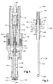
FIG. 1 is a cross-sectional view of an inwardly opening solenoid actuated fuel injector, in accordance with the invention; -
FIG. 2 is a cross-sectional view of a valve assembly of the inwardly opening fuel injector, in accordance with the invention; and -
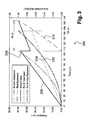
FIG. 3 is a graph illustrating armature and pintle movement of the solenoid actuated fuel injector in accordance with the present invention. - Corresponding reference characters indicate corresponding parts throughout the several views. The exemplification set out herein illustrates a preferred embodiment of the invention, in one form, and such exemplification is not to be construed as limiting the scope of the invention in any manner.
- Referring to
FIG. 1 , a solenoid actuated fuel injector 100 (inwardly opening-type shown) extends axially from afuel inlet 102 to afuel outlet 104 and includes a fueldelivery metering assembly 110 and asolenoid assembly 120.Fuel injector 100 may be, for example, an injector for direct injection. -
Assembly 110 includes the moving components and fuel containing components ofinjector 100, such as anupper housing 112, alower housing 114, apole piece 116 positioned betweenupper housing 112 andlower housing 114, and avalve assembly 130. Afuel tube 117 is positioned withinupper housing 112 and may be at least partially surrounded bypole piece 116. Avalve seat 118 may be integrated or attached tolower housing 114 proximate tofuel outlet 104.Valve seat 118 may be, for example, a beveled circular seat.Fuel tube 117,lower housing 114, andpole piece 116 enclose afuel passage 106. -
Solenoid assembly 120 includes anactuator housing 122, acoil assembly 124, and an electrical connector (not shown).Solenoid assembly 120 surroundspole piece 116. -
Valve assembly 130, shown in detail inFIG. 2 , includes apintle 132 and anarmature 134 and is positioned withinlower housing 114 such that a reciprocating movement ofvalve assembly 130 is enabled.Pintle 132 includes at one end avalve 136 that may have, for example, the geometric shape of a ball.Valve 136 functions as a reciprocably actuated valve and seals againstvalve seat 118, for example, in a circular sealing area.Armature 134 is slidably positioned onpintle 132 proximate an end opposite tovalve 136. Whenvalve assembly 130 is installed ininjector 100,armature 134 is positionedadjacent pole piece 116.Valve assembly 130, includingpintle 132,armature 134 andvalve 136, constitutes the moving mass offuel injector 100. By permitting slidable movement ofarmature 134 onpintle 132, the moving mass ofarmature 134 is separated from the moving mass of pintle/valve 132/136. The reciprocating movement ofvalve assembly 130 is actuated bysolenoid assembly 120 to regulate the fuel flow throughfuel outlet 104. Solenoid actuatedfuel injector 100 may be a pulse-width type. - As can be seen in
FIG. 1 and in detail inFIG. 2 ,armature 134 has a generally cylindrical shape, axially extends from atop surface 142 to abottom surface 144, and includes alarger diameter section 146 that extends fromtop surface 142 and asmaller diameter section 148 that terminates atbottom surface 144. Acenter aperture 150, extending fromtop surface 142 tobottom surface 144, is configured to closely but slidably be received over an outer circumferential surface ofpintle 132.Center aperture 150 is designed to guide reciprocating axial movement ofarmature 134 onpintle 132 without significant tilting aboutpintle axis 133.Armature 134 further includes a plurality of flow holes 154 that permit the flow of fuel througharmature 134. Whilearmature 134 is shown inFIGS. 1 and 2 to includelarger diameter section 146 andsmaller diameter section 148, other geometric configurations are possible. -
Armature 134 is positioned onpintle 132 between afirst armature stopper 138 and asecond armature stopper 140.First armature stopper 138 andsecond armature stopper 140 are rigidly attached topintle 132 at adistance 152 from each other.Distance 152 constitutes the distance in which armature 134 may move, axially, betweenfirst armature stopper 138 andsecond armature stopper 140.First armature stopper 138 andsecond armature stopper 140 may be joined withpintle 132, for example, by press fitting with subsequent welding.Distance 152 may be chosen based on an intended application ofinjector 100.First armature stopper 138 may include aradially extending shoulder 158 that facesbottom surface 144 ofarmature 134. - Preferably
pintle 132 extends beyondtop surface 142 ofarmature 134 and beyondsecond armature stopper 140. The extending section ofpintle 132 receives aprimary spring 160 and asecondary spring 162.Primary spring 160 preferably surroundspintle 132 and is captured betweensecond armature stopper 140 andfuel tube 117.Secondary spring 162 preferably surrounds primary spring andsecond armature stopper 140 and is captured betweentop surface 142 ofarmature 134 and a step integral withpole piece 116. -
Primary spring 160 provides a downward biasing force to pintle 132 and to armature 134 whenarmature 134 is in contact withsecond armature stopper 140, whilesecondary spring 162 provides a downward biasing force to armature 134 only.Secondary spring 162 preferably exerts a lower force on the armature thanprimary spring 160 exerts onpintle 132. - Again referring to
FIG. 1 , whenfuel injector 100 is closed as shown (solenoid de-energized),valve assembly 130 is in a lower position wherevalve 136 seals againstvalve seat 118 due to the biasing forces ofprimary spring 160 andsecondary spring 162. In the position shown,armature 134 is in contact withfirst armature stopper 138. During the opening event of injector 100 (solenoid energized),armature 134 starts moving up from the lower position against the biasing force ofsecondary spring 162. When armature 134 first makes contact withsecond armature stopper 140, the impact withsecond armature stopper 140 transmits an impulse to pintle 132 causingpintle 132 to accelerate quickly in the valve opening direction.Armature 134 andpintle 132 then move upward together against the combined biasing forces ofsecondary spring 162 andprimary spring 160 until the full pintle stroke is reached aftertop surface 142 ofarmature 134contacts pole piece 116. Note that the length of the pintle stroke may be larger than the length that armature 134 is able to move betweenfirst armature stopper 138 andsecond armature stopper 140. - Referring to
FIG. 3 , agraph 200 illustrates the movement ofarmature 134 andpintle 132 incurves curves pintle 132 can be reduced in accordance with the invention due to the initial acceleration ofarmature 134 prior to an upward movement ofpintle 132. Calculations illustrate inFIG. 3 , based on the direct injector design shown inFIG. 1 , that the ballistic time ofpintle 132 may be reduced by about 80 µs from about 144 µs of a prior art fixed valve assembly. Reducing the ballistic time ofpintle 132 extends the linear range offuel injector 100 during the opening event and enables a more precise control of flow at a low fuel flow rate. The calculations forgraph 200 have been based on an armature/pintle mass of about 5 gram, an average magnetic force of about 60 N, a valve stroke of about 50 µm, and an axial moving distance ofarmature 134 betweensecond armature stopper 140 andfirst armature stopper 138 of about 50 µm. In the example shown, the set force ofprimary spring 160 was about 20 N, and the set force ofsecondary spring 162 was about 5 N. - During the closing event of injector 100 (solenoid de-energized),
primary spring 160 pushespintle 132 andarmature 134 down concurrently, oncearmature 134 contactssecond armature stopper 140. During continued downward movement ofvalve assembly 130,top surface 142 ofarmature 134 stays in contact withsecond armature stopper 140. Whenvalve 136contacts valve seat 118,pintle 132 comes to a sudden stop whilearmature 134 continues to travel further down towardfirst armature stopper 138. - Accordingly, when
pintle 132 attempts to rebound fromseat 118 uponvalve 136 making initial contact withseat 118,armature 134 continues downward to impactfirst armature stopper 138, thereby inhibitingpintle 132 from rebounding. - Since
armature 134 moves withinfuel passage 106, and therefore within a fluid, fluid engulfs the surfaces contacted by the armature. Thus, a hydraulic suction force is created betweentop surface 142 ofarmature 134 andsecond armature stopper 140 whenarmature 134 first starts to separate from the second armature stopper under the force of the secondary spring and the armature inertia.Top surface 142 ofarmature 134 and the surface ofsecond armature stopper 140 that is in contact witharmature 134 in the open position are preferably flat surfaces. When the solenoid is first de-energized, andpintle 132 begins to move towardseat 118 under the force ofprimary spring 160,top surface 142 ofarmature 134 remains engaged withsecond armature stopper 140. Then, whenvalve 136first contacts seat 118,armature 134 continues its downward travel andsurface 134 begins to separate fromupper armature stopper 140. Fluid fills the space between the adjacent surfaces ofarmature 134 andupper armature stopper 140 creating a hydraulic suction force, thereby slowing the downward acceleration of the armature as it moves towardfirst armature stopper 138. - When
armature 134 nears contact withfirst armature stopper 138, the force ofarmature 134 acting against the first armature stopper may be dampened by squeezing the fluid out from betweenbottom surface 144 ofarmature 134 andshoulder 158 offirst armature stopper 138. The squeeze dampening force assists in stabilizing the armature on the first stopper without bounce. Due to the biasing down force ofsecondary spring 162,armature 134 stays in contact withfirst armature stopper 138 until the start of the next opening event. - If the masses of the pintle and armature, spring forces, seat material and surface areas and finishes of the armature contact surfaces are controlled in an optimal way, valve bounce may be completely eliminated. Various characteristics, including but not limited to, the
distance 152 betweensecond armature stopper 140 andfirst armature stopper 138, the roughness oftop surface 142 ofarmature 134 and of the contact surface ofsecond armature stopper 140, the surface areas oftop surface 142,bottom surface 144, the contact surface ofsecond armature stopper 140, and ofshoulder 158 offirst armature stopper 138, may be adjusted, for example through computational modulation, to control valve bounce ofvalve assembly 130. - While the anti-bounce mechanism in accordance with the invention has been described for inwardly opening fuel injectors, the same principals may be applicable to outwardly opening fuel injectors.
- While the anti-bounce mechanism as described above may be especially useful for application in direct injection fuel systems due to the relatively high fuel pressure of such systems, it may be applicable to other fuel systems operating at lower fuel pressures, such as multi-port injection fuel systems.
- While the invention has been described by reference to various specific embodiments, it should be understood that numerous changes may be made within the spirit and scope of the inventive concepts described. Accordingly, it is intended that the invention not be limited to the described embodiments, but will have full scope defined by the language of the following claims.
Claims (14)
- A solenoid actuated valve assembly (130), comprising:a pintle (132) including a valve (136) for mating with a valve seat (118);an armature (134) slidably positioned on said pintle (132) opposite from said valve (136);a first armature stopper (138) and a second armature stopper (140) both rigidly attached to said pintle (132) at a distance from each other and configured to allow axial movement of said armature (134) relative to said pintle (132);a primary spring (160) providing a first biasing force to said pintle (132) and to said armature (134) when said armature (134) is in contact with said second armature stopper (140); anda secondary spring (162) providing a second biasing force to said armature (134) only, wherein said second biasing down force is lower than said first biasing down force.
- The valve assembly (130) of Claim 1, wherein said primary spring (160) is captured between said second armature stopper (140) and a housing (112) of said solenoid actuated valve assembly (130).
- The valve assembly (130) of Claim 1 or 2, wherein said secondary spring (162) is captured between said armature (134) and a housing (112) of said solenoid actuated valve assembly (130).
- The valve assembly (130) of anyone of Claims 1 to 3, wherein said armature (134) has a generally cylindrical shape.
- The valve assembly (130) of anyone of Claims 1 to 4, wherein said armature (134) includes a center aperture (150) that slidably receives an outer circumferential surface of said pintle (132), wherein said center aperture (150) is configured to guide a reciprocating axial movement of said armature (134) on said pintle (132).
- The valve assembly (130) of anyone of Claims 1 to 5, wherein at least one of said first armature stopper (138) and said second armature stopper (140) is joined with said pintle (132) by press fitting and subsequent welding.
- The valve assembly (130) of anyone of Claims 1 to 6, wherein said first armature stopper (138) includes a radially extending shoulder (158) that faces said armature (134).
- The valve assembly (130) of anyone of Claims 1 to 7, further including a solenoid assembly (120), wherein said armature (134) moves from said first armature stopper (138) towards said second armature stopper (140)against said second biasing down force of said secondary spring (162) upon activation of said solenoid assembly (120), and wherein said armature (134) makes contact with said second armature stopper (140) and said pintle (132) is configured to move together with said armature (134) against the combined first and second biasing down forces of said primary (160) and said secondary (162) spring.
- The valve assembly (130) of anyone of Claims 1 to 8, further including a solenoid assembly (120), wherein after deactivation of said solenoid assembly (120) said primary spring (160) pushes said pintle (132) and said armature (134) concurrently until said valve (136) contacts said valve seat (118), wherein said armature (132) continues to travel downwards, and wherein said armature (132) contacts said first armature stopper (138).
- The valve assembly (130) of anyone of Claims 1 to 9, wherein said armature (134), first armature stopper (138) and second armature stopper (140) are configured to provide a hydraulic suction force between said armature (134) and said second armature stopper (140), and a squeeze dampening force between said armature (134) and said first armature stopper (138).
- A solenoid actuated fuel injector (100), comprising:a solenoid actuated valve assembly (130) according to anyone of claims 1 to 10, including a pintle (132) and an armature (134) slidably positioned on said pintle (132) wherein a moving mass of said armature (134) is separated from a moving mass of said pintle (132);a solenoid assembly (120) including a pole piece (116) configured to provide an axial movement of said valve assembly (130), said pole piece (116) enclosing a flow passage (106) and limiting travel of said valve assembly (130) in a first direction;a lower housing (114) including a valve seat (118) that sealingly receives a valve (136) of said pintle (132), said valve seat (118) limiting travel of said valve assembly (130) in a second direction;said primary spring (160) biasing said pintle (132) in a direction to move said valve (136) toward said valve seat (118); andsaid secondary spring (162) biasing said armature (134) away from said pole piece (116), wherein a bias force of said primary spring (160) and a bias force of said secondary spring (162) move said valve (136) of said pintle (132) toward said valve seat (118).
- The fuel injector (100) of Claim 11, wherein said primary spring (160) is positioned between an armature stopper (140) and a fluid tube (134) that is enclosed by said pole piece (116).
- The fuel injector (100) of Claim 11 or 12, wherein a travel distance of said armature (134) between a first (138) and a second (140) armature stopper is smaller than a length of a stroke of said pintle (132).
- The fuel injector (100) of anyone of Claims 11 to 13, wherein said armature (134) includes a plurality of through holes (154) that enable flow of a fluid through said armature (134), and wherein said fluid creates a hydraulic suction force between said armature (134) and a second armature stopper (138) and a squeeze dampening force between said armature (134) and a first armature stopper (140).
Priority Applications (1)
| Application Number | Priority Date | Filing Date | Title |
|---|---|---|---|
| EP09179022A EP2336544A1 (en) | 2009-12-14 | 2009-12-14 | Anti-bounce mechanism for fuel injectors |
Applications Claiming Priority (1)
| Application Number | Priority Date | Filing Date | Title |
|---|---|---|---|
| EP09179022A EP2336544A1 (en) | 2009-12-14 | 2009-12-14 | Anti-bounce mechanism for fuel injectors |
Publications (1)
| Publication Number | Publication Date |
|---|---|
| EP2336544A1 true EP2336544A1 (en) | 2011-06-22 |
Family
ID=42102326
Family Applications (1)
| Application Number | Title | Priority Date | Filing Date |
|---|---|---|---|
| EP09179022A Withdrawn EP2336544A1 (en) | 2009-12-14 | 2009-12-14 | Anti-bounce mechanism for fuel injectors |
Country Status (1)
| Country | Link |
|---|---|
| EP (1) | EP2336544A1 (en) |
Cited By (24)
| Publication number | Priority date | Publication date | Assignee | Title |
|---|---|---|---|---|
| JP2013174172A (en) * | 2012-02-24 | 2013-09-05 | Keihin Corp | Electromagnetic fuel injection valve |
| WO2013169482A1 (en) * | 2012-05-07 | 2013-11-14 | Tenneco Automotive Operating Company Inc. | Reagent injector |
| US8740113B2 (en) | 2010-02-10 | 2014-06-03 | Tenneco Automotive Operating Company, Inc. | Pressure swirl flow injector with reduced flow variability and return flow |
| CN104136761A (en) * | 2011-12-09 | 2014-11-05 | 现代凯菲克株式会社 | Direct injection fuel injector |
| US8910884B2 (en) | 2012-05-10 | 2014-12-16 | Tenneco Automotive Operating Company Inc. | Coaxial flow injector |
| US8973895B2 (en) | 2010-02-10 | 2015-03-10 | Tenneco Automotive Operating Company Inc. | Electromagnetically controlled injector having flux bridge and flux break |
| US8998114B2 (en) | 2010-02-10 | 2015-04-07 | Tenneco Automotive Operating Company, Inc. | Pressure swirl flow injector with reduced flow variability and return flow |
| WO2015143107A1 (en) * | 2014-03-20 | 2015-09-24 | GM Global Technology Operations LLC | Electromagnetic actuator structure |
| CN105275695A (en) * | 2014-05-27 | 2016-01-27 | 大陆汽车有限公司 | fuel injector |
| EP2985445A1 (en) | 2014-08-14 | 2016-02-17 | Continental Automotive GmbH | Solenoid actuated fluid injection valve |
| CN105593508A (en) * | 2013-10-10 | 2016-05-18 | 大陆汽车有限公司 | Injectors for combustion engines |
| EP3095998A1 (en) * | 2015-05-22 | 2016-11-23 | Robert Bosch GmbH | Fuel injector |
| US9624883B2 (en) | 2014-03-20 | 2017-04-18 | GM Global Technology Operations LLC | Smart actuator for plug and play |
| US9664158B2 (en) | 2014-03-20 | 2017-05-30 | GM Global Technology Operations LLC | Actuator with integrated driver |
| US9683472B2 (en) | 2010-02-10 | 2017-06-20 | Tenneco Automotive Operating Company Inc. | Electromagnetically controlled injector having flux bridge and flux break |
| US9726099B2 (en) | 2014-03-20 | 2017-08-08 | GM Global Technology Operations LLC | Actuator with feed forward control |
| US9777660B2 (en) | 2014-03-20 | 2017-10-03 | GM Global Technology Operations LLC | Parameter estimation in an actuator |
| US9777686B2 (en) | 2014-03-20 | 2017-10-03 | GM Global Technology Operations LLC | Actuator motion control |
| US9863355B2 (en) | 2014-03-20 | 2018-01-09 | GM Global Technology Operations LLC | Magnetic force based actuator control |
| US9879645B2 (en) | 2016-02-18 | 2018-01-30 | Caterpillar Inc. | Control valve bounce limiting mechanism for fuel injectors |
| US9932947B2 (en) | 2014-03-20 | 2018-04-03 | GM Global Technology Operations LLC | Actuator with residual magnetic hysteresis reset |
| US10190526B2 (en) | 2014-03-20 | 2019-01-29 | GM Global Technology Operations LLC | Alternating current drive for actuators |
| US10704444B2 (en) | 2018-08-21 | 2020-07-07 | Tenneco Automotive Operating Company Inc. | Injector fluid filter with upper and lower lip seal |
| WO2025134592A1 (en) * | 2023-12-20 | 2025-06-26 | Astemo株式会社 | Fuel injection device |
Citations (3)
| Publication number | Priority date | Publication date | Assignee | Title |
|---|---|---|---|---|
| DE19816315A1 (en) * | 1998-04-11 | 1999-10-14 | Bosch Gmbh Robert | Fuel injector |
| WO2002068811A1 (en) * | 2001-02-24 | 2002-09-06 | Robert Bosch Gmbh | Fuel injection valve |
| DE10256661A1 (en) * | 2002-12-04 | 2004-06-17 | Robert Bosch Gmbh | Fuel injection valve for the fuel injection system of a fuel engine wherein the preliminary stroke spring is arranged radially outwards in a recess of the armature |
-
2009
- 2009-12-14 EP EP09179022A patent/EP2336544A1/en not_active Withdrawn
Patent Citations (3)
| Publication number | Priority date | Publication date | Assignee | Title |
|---|---|---|---|---|
| DE19816315A1 (en) * | 1998-04-11 | 1999-10-14 | Bosch Gmbh Robert | Fuel injector |
| WO2002068811A1 (en) * | 2001-02-24 | 2002-09-06 | Robert Bosch Gmbh | Fuel injection valve |
| DE10256661A1 (en) * | 2002-12-04 | 2004-06-17 | Robert Bosch Gmbh | Fuel injection valve for the fuel injection system of a fuel engine wherein the preliminary stroke spring is arranged radially outwards in a recess of the armature |
Cited By (38)
| Publication number | Priority date | Publication date | Assignee | Title |
|---|---|---|---|---|
| US8973895B2 (en) | 2010-02-10 | 2015-03-10 | Tenneco Automotive Operating Company Inc. | Electromagnetically controlled injector having flux bridge and flux break |
| US9683472B2 (en) | 2010-02-10 | 2017-06-20 | Tenneco Automotive Operating Company Inc. | Electromagnetically controlled injector having flux bridge and flux break |
| US8740113B2 (en) | 2010-02-10 | 2014-06-03 | Tenneco Automotive Operating Company, Inc. | Pressure swirl flow injector with reduced flow variability and return flow |
| US8998114B2 (en) | 2010-02-10 | 2015-04-07 | Tenneco Automotive Operating Company, Inc. | Pressure swirl flow injector with reduced flow variability and return flow |
| CN104136761A (en) * | 2011-12-09 | 2014-11-05 | 现代凯菲克株式会社 | Direct injection fuel injector |
| CN103291514A (en) * | 2012-02-24 | 2013-09-11 | 株式会社京浜 | Electromagnetic fuel injection valve |
| JP2013174172A (en) * | 2012-02-24 | 2013-09-05 | Keihin Corp | Electromagnetic fuel injection valve |
| US8978364B2 (en) | 2012-05-07 | 2015-03-17 | Tenneco Automotive Operating Company Inc. | Reagent injector |
| CN104321508A (en) * | 2012-05-07 | 2015-01-28 | 天纳克汽车经营有限公司 | Reagent injector |
| US10465582B2 (en) | 2012-05-07 | 2019-11-05 | Tenneco Automotive Operating Company Inc. | Reagent injector |
| CN104321508B (en) * | 2012-05-07 | 2017-06-30 | 天纳克汽车经营有限公司 | Reagent injector |
| WO2013169482A1 (en) * | 2012-05-07 | 2013-11-14 | Tenneco Automotive Operating Company Inc. | Reagent injector |
| US8910884B2 (en) | 2012-05-10 | 2014-12-16 | Tenneco Automotive Operating Company Inc. | Coaxial flow injector |
| US9759113B2 (en) | 2012-05-10 | 2017-09-12 | Tenneco Automotive Operating Company Inc. | Coaxial flow injector |
| US10202953B2 (en) * | 2013-10-10 | 2019-02-12 | Continental Automotive Gmbh | Injector for a combustion engine |
| CN105593508A (en) * | 2013-10-10 | 2016-05-18 | 大陆汽车有限公司 | Injectors for combustion engines |
| KR20160060761A (en) * | 2013-10-10 | 2016-05-30 | 콘티넨탈 오토모티브 게엠베하 | Injector for a combustion engine |
| US20160237966A1 (en) * | 2013-10-10 | 2016-08-18 | Continental Automotive Gmbh | Injector For A Combustion Engine |
| US9657699B2 (en) | 2014-03-20 | 2017-05-23 | GM Global Technology Operations LLC | Actuator with integrated flux sensor |
| US9863355B2 (en) | 2014-03-20 | 2018-01-09 | GM Global Technology Operations LLC | Magnetic force based actuator control |
| US9624883B2 (en) | 2014-03-20 | 2017-04-18 | GM Global Technology Operations LLC | Smart actuator for plug and play |
| US10655583B2 (en) | 2014-03-20 | 2020-05-19 | GM Global Technology Operations LLC | Optimum current drive for a actuator control |
| US9726099B2 (en) | 2014-03-20 | 2017-08-08 | GM Global Technology Operations LLC | Actuator with feed forward control |
| US9726100B2 (en) | 2014-03-20 | 2017-08-08 | GM Global Technology Operations LLC | Actuator with deadbeat control |
| US10480674B2 (en) | 2014-03-20 | 2019-11-19 | GM Global Technology Operations LLC | Electromagnetic actuator structure |
| US9777660B2 (en) | 2014-03-20 | 2017-10-03 | GM Global Technology Operations LLC | Parameter estimation in an actuator |
| US9777686B2 (en) | 2014-03-20 | 2017-10-03 | GM Global Technology Operations LLC | Actuator motion control |
| US9664158B2 (en) | 2014-03-20 | 2017-05-30 | GM Global Technology Operations LLC | Actuator with integrated driver |
| WO2015143107A1 (en) * | 2014-03-20 | 2015-09-24 | GM Global Technology Operations LLC | Electromagnetic actuator structure |
| US9932947B2 (en) | 2014-03-20 | 2018-04-03 | GM Global Technology Operations LLC | Actuator with residual magnetic hysteresis reset |
| US10190526B2 (en) | 2014-03-20 | 2019-01-29 | GM Global Technology Operations LLC | Alternating current drive for actuators |
| CN105275695A (en) * | 2014-05-27 | 2016-01-27 | 大陆汽车有限公司 | fuel injector |
| CN105275695B (en) * | 2014-05-27 | 2020-03-20 | 大陆汽车有限公司 | Fuel injector |
| EP2985445A1 (en) | 2014-08-14 | 2016-02-17 | Continental Automotive GmbH | Solenoid actuated fluid injection valve |
| EP3095998A1 (en) * | 2015-05-22 | 2016-11-23 | Robert Bosch GmbH | Fuel injector |
| US9879645B2 (en) | 2016-02-18 | 2018-01-30 | Caterpillar Inc. | Control valve bounce limiting mechanism for fuel injectors |
| US10704444B2 (en) | 2018-08-21 | 2020-07-07 | Tenneco Automotive Operating Company Inc. | Injector fluid filter with upper and lower lip seal |
| WO2025134592A1 (en) * | 2023-12-20 | 2025-06-26 | Astemo株式会社 | Fuel injection device |
Similar Documents
| Publication | Publication Date | Title |
|---|---|---|
| EP2336544A1 (en) | Anti-bounce mechanism for fuel injectors | |
| US9435305B2 (en) | Valve assembly for an injection valve and injection valve | |
| US7163162B2 (en) | Fuel-injection valve | |
| EP3006720A1 (en) | Fuel injection valve | |
| US9664161B2 (en) | Valve assembly for an injection valve and injection valve | |
| US7156368B2 (en) | Solenoid actuated flow controller valve | |
| KR102332033B1 (en) | Fuel injector | |
| EP1783356B1 (en) | Fuel injector | |
| US10202953B2 (en) | Injector for a combustion engine | |
| US20150102135A1 (en) | Valve Assembly for an Injection Valve and Injection Valve | |
| US8919372B2 (en) | Valve assembly for an injection valve and injection valve | |
| EP1801409B1 (en) | Fuel injector | |
| JP2004519609A (en) | Solenoid valve for controlling the injection valve of an internal combustion engine | |
| US9995262B2 (en) | Fluid injection valve | |
| US20030111625A1 (en) | Magnetic valve for controlling an injection valve of an internal combustion engine | |
| EP2123899A1 (en) | Fuel injector with a solenoid actuator | |
| KR102139895B1 (en) | Injection valve with magnetic ring element | |
| KR20200103716A (en) | Fluid metering valve | |
| US11629678B2 (en) | Fuel injection valve and method for assembling same | |
| US20050056712A1 (en) | Fuel injection valve | |
| KR102706035B1 (en) | Valve for metering a fluid | |
| KR102042912B1 (en) | Solenoid valve for a fuel injection system, and high pressure fuel pump | |
| CN106795843A (en) | Injectors for injecting fluids | |
| JP2010159811A (en) | solenoid valve |
Legal Events
| Date | Code | Title | Description |
|---|---|---|---|
| PUAI | Public reference made under article 153(3) epc to a published international application that has entered the european phase |
Free format text: ORIGINAL CODE: 0009012 |
|
| AK | Designated contracting states |
Kind code of ref document: A1 Designated state(s): AT BE BG CH CY CZ DE DK EE ES FI FR GB GR HR HU IE IS IT LI LT LU LV MC MK MT NL NO PL PT RO SE SI SK SM TR |
|
| AX | Request for extension of the european patent |
Extension state: AL BA RS |
|
| STAA | Information on the status of an ep patent application or granted ep patent |
Free format text: STATUS: THE APPLICATION IS DEEMED TO BE WITHDRAWN |
|
| 18D | Application deemed to be withdrawn |
Effective date: 20111123 |