EP2336536A1 - Engine rpm control device - Google Patents
Engine rpm control device Download PDFInfo
- Publication number
- EP2336536A1 EP2336536A1 EP09820537A EP09820537A EP2336536A1 EP 2336536 A1 EP2336536 A1 EP 2336536A1 EP 09820537 A EP09820537 A EP 09820537A EP 09820537 A EP09820537 A EP 09820537A EP 2336536 A1 EP2336536 A1 EP 2336536A1
- Authority
- EP
- European Patent Office
- Prior art keywords
- rotation speed
- engine rotation
- engine
- target
- abnormality
- Prior art date
- Legal status (The legal status is an assumption and is not a legal conclusion. Google has not performed a legal analysis and makes no representation as to the accuracy of the status listed.)
- Withdrawn
Links
- 238000001514 detection method Methods 0.000 claims abstract description 12
- 230000005856 abnormality Effects 0.000 claims description 55
- 206010063659 Aversion Diseases 0.000 claims description 21
- 238000002347 injection Methods 0.000 claims description 18
- 239000007924 injection Substances 0.000 claims description 18
- 239000000446 fuel Substances 0.000 claims description 9
- 230000007704 transition Effects 0.000 description 4
- 230000008054 signal transmission Effects 0.000 description 3
- 238000010586 diagram Methods 0.000 description 2
- 230000002159 abnormal effect Effects 0.000 description 1
- 239000000498 cooling water Substances 0.000 description 1
- 230000000694 effects Effects 0.000 description 1
- 239000010687 lubricating oil Substances 0.000 description 1
- XLYOFNOQVPJJNP-UHFFFAOYSA-N water Substances O XLYOFNOQVPJJNP-UHFFFAOYSA-N 0.000 description 1
Images


Classifications
-
- F—MECHANICAL ENGINEERING; LIGHTING; HEATING; WEAPONS; BLASTING
- F02—COMBUSTION ENGINES; HOT-GAS OR COMBUSTION-PRODUCT ENGINE PLANTS
- F02D—CONTROLLING COMBUSTION ENGINES
- F02D45/00—Electrical control not provided for in groups F02D41/00 - F02D43/00
-
- F—MECHANICAL ENGINEERING; LIGHTING; HEATING; WEAPONS; BLASTING
- F02—COMBUSTION ENGINES; HOT-GAS OR COMBUSTION-PRODUCT ENGINE PLANTS
- F02D—CONTROLLING COMBUSTION ENGINES
- F02D31/00—Use of speed-sensing governors to control combustion engines, not otherwise provided for
- F02D31/001—Electric control of rotation speed
-
- F—MECHANICAL ENGINEERING; LIGHTING; HEATING; WEAPONS; BLASTING
- F02—COMBUSTION ENGINES; HOT-GAS OR COMBUSTION-PRODUCT ENGINE PLANTS
- F02D—CONTROLLING COMBUSTION ENGINES
- F02D35/00—Controlling engines, dependent on conditions exterior or interior to engines, not otherwise provided for
-
- F—MECHANICAL ENGINEERING; LIGHTING; HEATING; WEAPONS; BLASTING
- F02—COMBUSTION ENGINES; HOT-GAS OR COMBUSTION-PRODUCT ENGINE PLANTS
- F02D—CONTROLLING COMBUSTION ENGINES
- F02D41/00—Electrical control of supply of combustible mixture or its constituents
- F02D41/02—Circuit arrangements for generating control signals
- F02D41/021—Introducing corrections for particular conditions exterior to the engine
-
- F—MECHANICAL ENGINEERING; LIGHTING; HEATING; WEAPONS; BLASTING
- F02—COMBUSTION ENGINES; HOT-GAS OR COMBUSTION-PRODUCT ENGINE PLANTS
- F02D—CONTROLLING COMBUSTION ENGINES
- F02D41/00—Electrical control of supply of combustible mixture or its constituents
- F02D41/02—Circuit arrangements for generating control signals
- F02D41/04—Introducing corrections for particular operating conditions
- F02D41/12—Introducing corrections for particular operating conditions for deceleration
-
- F—MECHANICAL ENGINEERING; LIGHTING; HEATING; WEAPONS; BLASTING
- F02—COMBUSTION ENGINES; HOT-GAS OR COMBUSTION-PRODUCT ENGINE PLANTS
- F02D—CONTROLLING COMBUSTION ENGINES
- F02D41/00—Electrical control of supply of combustible mixture or its constituents
- F02D41/22—Safety or indicating devices for abnormal conditions
-
- F—MECHANICAL ENGINEERING; LIGHTING; HEATING; WEAPONS; BLASTING
- F02—COMBUSTION ENGINES; HOT-GAS OR COMBUSTION-PRODUCT ENGINE PLANTS
- F02D—CONTROLLING COMBUSTION ENGINES
- F02D2200/00—Input parameters for engine control
- F02D2200/50—Input parameters for engine control said parameters being related to the vehicle or its components
- F02D2200/501—Vehicle speed
-
- Y—GENERAL TAGGING OF NEW TECHNOLOGICAL DEVELOPMENTS; GENERAL TAGGING OF CROSS-SECTIONAL TECHNOLOGIES SPANNING OVER SEVERAL SECTIONS OF THE IPC; TECHNICAL SUBJECTS COVERED BY FORMER USPC CROSS-REFERENCE ART COLLECTIONS [XRACs] AND DIGESTS
- Y02—TECHNOLOGIES OR APPLICATIONS FOR MITIGATION OR ADAPTATION AGAINST CLIMATE CHANGE
- Y02T—CLIMATE CHANGE MITIGATION TECHNOLOGIES RELATED TO TRANSPORTATION
- Y02T10/00—Road transport of goods or passengers
- Y02T10/10—Internal combustion engine [ICE] based vehicles
- Y02T10/40—Engine management systems
Definitions
- the present invention relates to an art of an engine rotation speed control device having a means for correcting target engine rotation speeds at the time of detecting engine abnormality.
- an engine rotation speed control device which has a control means reducing a target engine rotation speed for the safety.
- the Patent Literature 1 discloses a rotation control device of a diesel engine for a ship which reduces a fuel injection amount so as to reduce a target engine rotation speed in the case that a command engine rotation speed by a control lever in abnormality detection mode is equal to or more than a predetermined value and an actual engine rotation speed is equal to or more than the predetermined value.
- the purpose of the present invention is to provide an engine rotation speed control device which gradually reduces the output speed of an object driven by an engine when the engine rotation speed is reduced.
- An engine rotation speed control device of the present invention has an actual engine rotation speed detection means, a target engine rotation speed command means, a means for calculating a fuel injection amount based on an actual engine rotation speed and a target engine rotation speed, an engine abnormality detection means, and a means for correcting the target engine rotation speed at the time of detecting engine abnormality.
- the means for correcting the target engine rotation speed at the time of detecting the engine abnormality has a storage unit.
- the target engine rotation speed is corrected so as to make the target engine rotation speed shift to a predetermined abnormality aversion engine rotation speed based on a map of correlation characteristic between the actual engine rotation speed and an output speed of an object driven by the engine stored in the storage unit while a deceleration rate of the output speed of the object is held at a predetermined value.
- the target engine rotation speed is corrected so as to make the target engine rotation speed shift to a predetermined abnormality aversion engine rotation speed while the deceleration rate of the output speed of the object is increased with time from the start of the deceleration to the finish of the deceleration.
- the engine rotation speed control device of the present invention has a selection means selecting one of controls, i.e., the control in which the target engine rotation speed is corrected so as to make the target engine rotation speed shift to a predetermined abnormality aversion engine rotation speed while the deceleration rate of the output speed of the object driven by the engine is held at a predetermined value, and the control in which the target engine rotation speed is corrected so as to make the target engine rotation speed shift to a predetermined abnormality aversion engine rotation speed while the deceleration rate of the output speed of the object is increased with time from the start of the deceleration to the finish of the deceleration based on the correlation characteristic between the engine rotation speed and an output speed of the object.
- the engine rotation speed control device of the present invention at the time of detecting the engine abnormality, the output speed itself of the object driven by the engine is reduced while the deceleration rate is held at a predetermined value, whereby an operator feels softly the deceleration at the time of detecting the abnormality of the engine.
- the engine rotation speed control device of the present invention at the time of detecting the engine abnormality, the output speed itself of the object driven by the engine is reduced while the deceleration rate is increased with time, whereby an operator feels softly the deceleration at the time of detecting the abnormality of the engine.
- the output speed itself of the object driven by the engine is reduced while the deceleration rate is held at a predetermined value, or reduced while the deceleration rate is increased with time, whereby an operator feels softly the deceleration at the time of detecting the abnormality of the engine.
- the operator can optionally select the deceleration rate characteristics of the output speed at the time of detecting the abnormality of the engine.
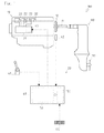
- Fig. 1 is a schematic drawing of an engine according to an embodiment of the present invention.
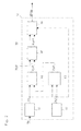
- Fig. 2 is a block diagram of signal transmission of derating control of the engine.
- Fig. 3 is a graph showing the transition of an embodiment 1 of the derating control.
- Fig. 4 is a graph showing the transition of an embodiment 2 of the derating control.
- the engine 100 is a direct injection type 4-cylindered engine which drives a propulsion unit 110 as a marine engine mounted on a ship.
- the engine 100 has an engine body 10 and an engine rotation speed control device 20.
- An output shaft 11 of the engine 100 is connected to the propulsion unit 110.
- a flywheel 12 is provided on the output shaft 11 of the engine 100.
- the propulsion unit 110 drives a propeller 111 by the drive of the output shaft 11.
- the engine body 10 has a fuel injection pump 21 and four injectors 22. Fuel is pressingly sent by the fuel injection pump 21 and injected into cylinders through the injectors 22.
- the fuel injection pump 21 is controlled in the injection amount by an electronic governor mechanism including a rack actuator 43.
- the engine rotation speed control device 20 performs control in which target engine rotation speed is reduced at the time of detecting engine abnormality (hereinafter, referred to as derating control).
- the engine rotation speed control device 20 is constructed by connecting an engine control unit (hereinafter, referred to as ECU) 40, an accelerator 41, an engine rotation speed sensor 42, the rack actuator 43 and a setting unit 44.
- ECU engine control unit
- the ECU 40 has an arithmetical unit 50 and a storage unit 51.
- the accelerator 41 is provided in an operator's seat of a ship.
- the accelerator 41 has a function for commanding the ECU 40 a command engine rotation speed Nset as a target engine rotation speed command means.
- the engine rotation speed sensor 42 is provided near the flywheel 12.
- the engine rotation speed sensor 42 has a function for detecting an actual engine rotation speed Ne and transmitting it to the ECU 40 as an actual engine rotation speed detection means.
- the rack actuator 43 controls a fuel injection amount based on a final target injection amount Qfinal calculated by an injection amount calculation unit 66 discussed later.
- the setting unit 44 has a function for selecting or setting various functions of the engine 100 as a selection means.
- the arithmetical unit 50 has functions as a Vs calculation unit 61, an abnormality detection unit 62, a Vset pattern generation part 63, a Nset' calculation unit 64, a Nset switch unit 65 and the injection amount calculation unit 66.
- the Vs calculation unit 61 has a function for converting the actual engine rotation speed Ne transmitted from the engine rotation speed sensor 42 into a ship speed Vs so as to calculate the ship speed Vs.
- the correlation characteristic between the actual engine rotation speed Ne and the ship speed Vs as the correlation characteristic between engine rotation speed and output speed of an object driven by the engine is previously set in the storage unit 51 as a map.
- the actual position of the ship may be grasped with a GPS so as to calculate the ship speed Vs.
- the ship speed Vs may be calculated from resistance of water at the time of sailing.
- the abnormality detection unit 62 has a function as an engine abnormality detection means. More concretely, the abnormality detection unit 62 has a function for transmitting a signal of ON/OFF of a derating requirement flag to the Vset pattern generation part 63 and the injection amount calculation unit 66 when the abnormality of the engine 100 is detected.
- the abnormality of the engine 100 is the case that the ECU 40 recognizes the abnormal state in which temperature of cooling water of the engine 100 becomes larger than a set value or pressure of lubricating oil of the engine 100 becomes larger than a set value, for example.
- the Vset pattern generation part 63, the Nset' calculation unit 64 and the Nset switch unit 65 have a function as a means for correcting target engine rotation speed in the case that the abnormality of the engine is detected. More concretely, the Vset pattern generation part 63 has a function for calculating a target ship speed Vset from the state of ON/OFF of the derating requirement flag and the actual ship speed Vs based on a Vset pattern. The details of the Vset pattern will be described later.
- the Nset' calculation unit 64 has a function for calculating a derating target engine rotation speed Nset' so as to make deflection between the ship speed Vs and the target ship speed Vset be zero.
- the Nset switch unit 65 has a function for selecting the derating target engine rotation speed Nset' or the command engine rotation speed Nset as a final target engine rotation speed Nsetf based on the state of ON/OFF of the derating requirement flag. More concretely, the Nset switch unit 65 selects the derating target engine rotation speed Nset' as the final target engine rotation speed Nsetf when the derating requirement flag is set, and selects the command engine rotation speed Nset as the final target engine rotation speed Nsetf when the derating requirement flag is cleared.
- the injection amount calculation unit 66 has a function as a fuel injection amount calculation means. More concretely, the injection amount calculation unit 66 has a function for calculating the final target injection amount Qfinal so as to make deflection between the final target engine rotation speed Nsetf and the actual engine rotation speed Ne transmitted from the engine rotation speed sensor 42 be zero.
- the axis of abscissas indicates the time (t).
- the upper portion indicates the state of ON/OFF of the derating requirement flag
- the middle portion indicates the target ship speed Vset (a solid line in the graph) and the ship speed Vs (a broken line in the graph)
- the lower portion indicates the command engine rotation speed Nset (a broken line in the graph) and the derating target engine rotation speed Nset' (a solid line in the graph).
- the lower portion indicates the derating target engine rotation speed Nset' or the command engine rotation speed Nset selected as the final target engine rotation speed Nsetf.
- the target ship speed Vset at the time that the state of ON of the derating requirement flag is transmitted is defined as an initial ship speed V1
- the command engine rotation speed Nset at the time that the state of ON of the derating requirement flag is transmitted is defined as an initial engine rotation speed N1.
- an engine rotation speed which is the final target of the derating control is defined as an abnormality aversion engine rotation speed N2
- the ship speed corresponding to the abnormality aversion engine rotation speed N2 is defined as an abnormality aversion ship speed V2.
- a first Vset pattern P1 of the embodiment 1 the ship speed is shifted from the initial ship speed V1 toward the abnormality aversion ship speed V2 while the deceleration rate of the target ship speed Vset is held at a predetermined value.
- the Vset pattern P1 is previously stored in the storage unit 51 of the ECU 40 as a map.
- the target ship speed Vset of the deceleration from the initial ship speed V 1 to the abnormality aversion ship speed V2 with the predetermined deceleration rate is calculated, and the derating target engine rotation speed Nset' corresponding to this target ship speed Vset is calculated.
- the ship speed Vs itself of an object driven by the engine 100 is decelerated with the predetermined deceleration rate, whereby an operator feels softly the deceleration at the time of detecting the abnormality of the engine.
- the ship speed is shifted from the initial ship speed V1 toward the abnormality aversion ship speed V2 while the deceleration rate of the target ship speed Vset is increased with time.
- the Vset pattern P1 is previously stored in the storage unit 51 of the ECU 40 as a map.
- the target ship speed Vset of the deceleration from the initial ship speed V1 to the abnormality aversion ship speed V2 with the deceleration rate increased with time is calculated, and the derating target engine rotation speed Nset' corresponding to this target ship speed Vset is calculated.
- the ship speed Vs itself of the ship which is an object driven by the engine 100 is decelerated with the deceleration rate increased with time, whereby an operator feels softly the deceleration at the time of detecting the abnormality of the engine.
- the state is conceivable that an operator senses the engine abnormality in the derating control and operates the accelerator 41 so as to perform reduction operation and obtain a target engine rotation speed smaller than the abnormality aversion engine rotation speed N2. Therefore, in the embodiments 1 and 2, when the accelerator 41 is operated in the derating control and the command engine rotation speed Nset becomes smaller than the abnormality aversion engine rotation speed N2, the final target engine rotation speed Nsetf is returned to the command engine rotation speed Nset.
- the command engine rotation speed Nset is not permitted to be larger than the abnormality aversion engine rotation speed N2.
- the operation of the accelerator 41 can be made effective, whereby the operability of the ship is improved.
- an operator can select optionally one of the Vset pattern P1 and the second Vset pattern P2 with the setting unit 44. Accordingly, at the time of detecting the abnormality of the engine 100, the operator can select optionally the deceleration rate characteristic of the ship speed Vs of the ship which is an object driven by the engine 100, whereby the operability of the ship is improved.
- the engine control according to the present invention can be employed effectively in not only an engine of a ship but also an engine in which engine rotation speed is reduced automatically at the time of detecting abnormality.
- an operator feels softly the deceleration at the time of detecting the abnormality of the engine, whereby the invention is useful industrially.
Landscapes
- Engineering & Computer Science (AREA)
- Chemical & Material Sciences (AREA)
- Combustion & Propulsion (AREA)
- Mechanical Engineering (AREA)
- General Engineering & Computer Science (AREA)
- Combined Controls Of Internal Combustion Engines (AREA)
- Control Of Vehicle Engines Or Engines For Specific Uses (AREA)
- Electrical Control Of Air Or Fuel Supplied To Internal-Combustion Engine (AREA)
Abstract
Description
- The present invention relates to an art of an engine rotation speed control device having a means for correcting target engine rotation speeds at the time of detecting engine abnormality.
- Conventionally, an engine rotation speed control device is known which has a control means reducing a target engine rotation speed for the safety. For example, the Patent Literature 1 discloses a rotation control device of a diesel engine for a ship which reduces a fuel injection amount so as to reduce a target engine rotation speed in the case that a command engine rotation speed by a control lever in abnormality detection mode is equal to or more than a predetermined value and an actual engine rotation speed is equal to or more than the predetermined value.
- In the rotation control device of the diesel engine for the ship disclosed in the Patent Literature 1, an object to be controlled is the engine rotation speed. Therefore, in the case that the reduction tendency of the ship speed itself is not necessarily in agreement with that of the engine rotation speed, an operator cannot feel softly the deceleration at the time of detecting the abnormality of the engine. In other words, in an engine rotation speed control device having a control means for reducing the target engine rotation speed for the safety, in the case that reduction tendency of an output speed of an object driven by the engine is not in agreement with that of the engine rotation speed, an operator cannot feel softly the deceleration at the time of detecting the abnormality of the engine.
Patent Literature 1: the Japanese Patent No.2689119 - The purpose of the present invention is to provide an engine rotation speed control device which gradually reduces the output speed of an object driven by an engine when the engine rotation speed is reduced.
- An engine rotation speed control device of the present invention has an actual engine rotation speed detection means, a target engine rotation speed command means, a means for calculating a fuel injection amount based on an actual engine rotation speed and a target engine rotation speed, an engine abnormality detection means, and a means for correcting the target engine rotation speed at the time of detecting engine abnormality. The means for correcting the target engine rotation speed at the time of detecting the engine abnormality has a storage unit. The target engine rotation speed is corrected so as to make the target engine rotation speed shift to a predetermined abnormality aversion engine rotation speed based on a map of correlation characteristic between the actual engine rotation speed and an output speed of an object driven by the engine stored in the storage unit while a deceleration rate of the output speed of the object is held at a predetermined value.
- In the engine rotation speed control device of the present invention, the target engine rotation speed is corrected so as to make the target engine rotation speed shift to a predetermined abnormality aversion engine rotation speed while the deceleration rate of the output speed of the object is increased with time from the start of the deceleration to the finish of the deceleration.
- The engine rotation speed control device of the present invention has a selection means selecting one of controls, i.e., the control in which the target engine rotation speed is corrected so as to make the target engine rotation speed shift to a predetermined abnormality aversion engine rotation speed while the deceleration rate of the output speed of the object driven by the engine is held at a predetermined value, and the control in which the target engine rotation speed is corrected so as to make the target engine rotation speed shift to a predetermined abnormality aversion engine rotation speed while the deceleration rate of the output speed of the object is increased with time from the start of the deceleration to the finish of the deceleration based on the correlation characteristic between the engine rotation speed and an output speed of the object.
- According to the engine rotation speed control device of the present invention, at the time of detecting the engine abnormality, the output speed itself of the object driven by the engine is reduced while the deceleration rate is held at a predetermined value, whereby an operator feels softly the deceleration at the time of detecting the abnormality of the engine.
- According to the engine rotation speed control device of the present invention, at the time of detecting the engine abnormality, the output speed itself of the object driven by the engine is reduced while the deceleration rate is increased with time, whereby an operator feels softly the deceleration at the time of detecting the abnormality of the engine.
- According to the engine rotation speed control device of the present invention, at the time of detecting the engine abnormality, the output speed itself of the object driven by the engine is reduced while the deceleration rate is held at a predetermined value, or reduced while the deceleration rate is increased with time, whereby an operator feels softly the deceleration at the time of detecting the abnormality of the engine. Furthermore, the operator can optionally select the deceleration rate characteristics of the output speed at the time of detecting the abnormality of the engine.
-
- [
Fig. 1 ] It is a schematic drawing of an engine according to an embodiment of the present invention. - [
Fig. 2 ] It is a block diagram of signal transmission of derating control of the engine. - [
Fig. 3 ] It is a graph of transition of an embodiment 1 of the derating control of the engine. - [
Fig. 4 ] It is a graph of transition of an embodiment 2 of the derating control of the engine. -
- 10
- engine body
- 20
- engine rotation speed control device
- 40
- ECU
- 41
- accelerator
- 42
- engine rotation speed sensor
- 44
- setting unit
- 50
- arithmetical unit
- 51
- storage unit
- 61
- Vs calculation unit
- 62
- abnormality detection unit
- 63
- Vset pattern generation part
- 64
- Nset' calculation unit
- 65
- Nset switch unit
- 66
- inj ection amount calculation unit
- 100
- engine
- Vs
- ship speed
- Vset
- target ship speed
- Nset
- command engine rotation speed
- Nset'
- derating target engine rotation speed
- N2
- abnormality aversion engine rotation speed
- P1
- first Vset pattern
- P2
- second Vset pattern
- Next, explanation will be given on the mode for carrying out the present invention.
Fig. 1 is a schematic drawing of an engine according to an embodiment of the present invention.Fig. 2 is a block diagram of signal transmission of derating control of the engine.Fig. 3 is a graph showing the transition of an embodiment 1 of the derating control.Fig. 4 is a graph showing the transition of an embodiment 2 of the derating control. - Explanation will be given on an
engine 100 which is an embodiment of the present invention. Theengine 100 is a direct injection type 4-cylindered engine which drives apropulsion unit 110 as a marine engine mounted on a ship. Theengine 100 has an engine body 10 and an engine rotationspeed control device 20. - An output shaft 11 of the
engine 100 is connected to thepropulsion unit 110. A flywheel 12 is provided on the output shaft 11 of theengine 100. Thepropulsion unit 110 drives apropeller 111 by the drive of the output shaft 11. - The engine body 10 has a
fuel injection pump 21 and fourinjectors 22. Fuel is pressingly sent by thefuel injection pump 21 and injected into cylinders through theinjectors 22. Thefuel injection pump 21 is controlled in the injection amount by an electronic governor mechanism including a rack actuator 43. - The engine rotation
speed control device 20 performs control in which target engine rotation speed is reduced at the time of detecting engine abnormality (hereinafter, referred to as derating control). The engine rotationspeed control device 20 is constructed by connecting an engine control unit (hereinafter, referred to as ECU) 40, an accelerator 41, an engine rotation speed sensor 42, the rack actuator 43 and a setting unit 44. - The ECU 40 has an
arithmetical unit 50 and a storage unit 51. The accelerator 41 is provided in an operator's seat of a ship. The accelerator 41 has a function for commanding the ECU 40 a command engine rotation speed Nset as a target engine rotation speed command means. The engine rotation speed sensor 42 is provided near the flywheel 12. The engine rotation speed sensor 42 has a function for detecting an actual engine rotation speed Ne and transmitting it to the ECU 40 as an actual engine rotation speed detection means. The rack actuator 43 controls a fuel injection amount based on a final target injection amount Qfinal calculated by an injectionamount calculation unit 66 discussed later. The setting unit 44 has a function for selecting or setting various functions of theengine 100 as a selection means. - Explanation will be given on signal transmission of the derating control referring to
Fig. 2 . Thearithmetical unit 50 has functions as a Vs calculation unit 61, an abnormality detection unit 62, a Vsetpattern generation part 63, a Nset' calculation unit 64, aNset switch unit 65 and the injectionamount calculation unit 66. - The Vs calculation unit 61 has a function for converting the actual engine rotation speed Ne transmitted from the engine rotation speed sensor 42 into a ship speed Vs so as to calculate the ship speed Vs. The correlation characteristic between the actual engine rotation speed Ne and the ship speed Vs as the correlation characteristic between engine rotation speed and output speed of an object driven by the engine is previously set in the storage unit 51 as a map. Instead of employing the Vs calculation unit 61, the actual position of the ship may be grasped with a GPS so as to calculate the ship speed Vs. The ship speed Vs may be calculated from resistance of water at the time of sailing.
- The abnormality detection unit 62 has a function as an engine abnormality detection means. More concretely, the abnormality detection unit 62 has a function for transmitting a signal of ON/OFF of a derating requirement flag to the Vset
pattern generation part 63 and the injectionamount calculation unit 66 when the abnormality of theengine 100 is detected. The abnormality of theengine 100 is the case that the ECU 40 recognizes the abnormal state in which temperature of cooling water of theengine 100 becomes larger than a set value or pressure of lubricating oil of theengine 100 becomes larger than a set value, for example. - The Vset
pattern generation part 63, the Nset' calculation unit 64 and theNset switch unit 65 have a function as a means for correcting target engine rotation speed in the case that the abnormality of the engine is detected.
More concretely, the Vsetpattern generation part 63 has a function for calculating a target ship speed Vset from the state of ON/OFF of the derating requirement flag and the actual ship speed Vs based on a Vset pattern. The details of the Vset pattern will be described later.
The Nset' calculation unit 64 has a function for calculating a derating target engine rotation speed Nset' so as to make deflection between the ship speed Vs and the target ship speed Vset be zero.
TheNset switch unit 65 has a function for selecting the derating target engine rotation speed Nset' or the command engine rotation speed Nset as a final target engine rotation speed Nsetf based on the state of ON/OFF of the derating requirement flag. More concretely, theNset switch unit 65 selects the derating target engine rotation speed Nset' as the final target engine rotation speed Nsetf when the derating requirement flag is set, and selects the command engine rotation speed Nset as the final target engine rotation speed Nsetf when the derating requirement flag is cleared. - The injection
amount calculation unit 66 has a function as a fuel injection amount calculation means. More concretely, the injectionamount calculation unit 66 has a function for calculating the final target injection amount Qfinal so as to make deflection between the final target engine rotation speed Nsetf and the actual engine rotation speed Ne transmitted from the engine rotation speed sensor 42 be zero. - Explanation will be given on an embodiment 1 of the derating control referring to
Fig. 3 . InFig. 3 , the axis of abscissas indicates the time (t). In the axis of ordinates, the upper portion indicates the state of ON/OFF of the derating requirement flag, the middle portion indicates the target ship speed Vset (a solid line in the graph) and the ship speed Vs (a broken line in the graph), and the lower portion indicates the command engine rotation speed Nset (a broken line in the graph) and the derating target engine rotation speed Nset' (a solid line in the graph). The lower portion indicates the derating target engine rotation speed Nset' or the command engine rotation speed Nset selected as the final target engine rotation speed Nsetf. - In
Fig. 3 , the target ship speed Vset at the time that the state of ON of the derating requirement flag is transmitted is defined as an initial ship speed V1, and the command engine rotation speed Nset at the time that the state of ON of the derating requirement flag is transmitted is defined as an initial engine rotation speed N1. Furthermore, an engine rotation speed which is the final target of the derating control is defined as an abnormality aversion engine rotation speed N2, and the ship speed corresponding to the abnormality aversion engine rotation speed N2 is defined as an abnormality aversion ship speed V2. - In a first Vset pattern P1 of the embodiment 1, the ship speed is shifted from the initial ship speed V1 toward the abnormality aversion ship speed V2 while the deceleration rate of the target ship speed Vset is held at a predetermined value. The Vset pattern P1 is previously stored in the storage unit 51 of the ECU 40 as a map.
- In the embodiment 1, when the state of ON of the derating requirement flag is transmitted, the target ship speed Vset of the deceleration from the initial ship speed V 1 to the abnormality aversion ship speed V2 with the predetermined deceleration rate is calculated, and the derating target engine rotation speed Nset' corresponding to this target ship speed Vset is calculated.
- Accordingly, at the time of detecting the abnormality of the
engine 100, the ship speed Vs itself of an object driven by theengine 100 is decelerated with the predetermined deceleration rate, whereby an operator feels softly the deceleration at the time of detecting the abnormality of the engine. - Explanation will be given on an embodiment 2 of the derating control referring to
Fig. 4 . InFig. 4 , what the axis of abscissas and the axis of ordinates indicate is the same as that ofFig. 3 and explanation thereof is omitted. The initial ship speed V1, the abnormality aversion ship speed V2, the initial engine rotation speed N1 and the abnormality aversion engine rotation speed N2 are defined similarly to the embodiment 1. - In a second Vset pattern P2 of the embodiment 2, the ship speed is shifted from the initial ship speed V1 toward the abnormality aversion ship speed V2 while the deceleration rate of the target ship speed Vset is increased with time. The Vset pattern P1 is previously stored in the storage unit 51 of the ECU 40 as a map.
- In the embodiment 2, when the state of ON of the derating requirement flag is transmitted, the target ship speed Vset of the deceleration from the initial ship speed V1 to the abnormality aversion ship speed V2 with the deceleration rate increased with time is calculated, and the derating target engine rotation speed Nset' corresponding to this target ship speed Vset is calculated.
- Accordingly, at the time of detecting the abnormality of the
engine 100, the ship speed Vs itself of the ship which is an object driven by theengine 100 is decelerated with the deceleration rate increased with time, whereby an operator feels softly the deceleration at the time of detecting the abnormality of the engine. - The state is conceivable that an operator senses the engine abnormality in the derating control and operates the accelerator 41 so as to perform reduction operation and obtain a target engine rotation speed smaller than the abnormality aversion engine rotation speed N2.
Therefore, in the embodiments 1 and 2, when the accelerator 41 is operated in the derating control and the command engine rotation speed Nset becomes smaller than the abnormality aversion engine rotation speed N2, the final target engine rotation speed Nsetf is returned to the command engine rotation speed Nset. The command engine rotation speed Nset is not permitted to be larger than the abnormality aversion engine rotation speed N2. - Accordingly, after the reduction by the derating control, the operation of the accelerator 41 can be made effective, whereby the operability of the ship is improved.
- Furthermore, explanation will be given on an embodiment 3 of the derating control. In the Vset pattern of the embodiment 3, an operator can select optionally one of the Vset pattern P1 and the second Vset pattern P2 with the setting unit 44.
Accordingly, at the time of detecting the abnormality of theengine 100, the operator can select optionally the deceleration rate characteristic of the ship speed Vs of the ship which is an object driven by theengine 100, whereby the operability of the ship is improved. - The engine control according to the present invention can be employed effectively in not only an engine of a ship but also an engine in which engine rotation speed is reduced automatically at the time of detecting abnormality.
- According to the engine rotation speed control device of the present invention, an operator feels softly the deceleration at the time of detecting the abnormality of the engine, whereby the invention is useful industrially.
Claims (3)
- An engine rotation speed control device comprising:an actual engine rotation speed detection means;a target engine rotation speed command means;a means for calculating a fuel injection amount based on an actual engine rotation speed and a target engine rotation speed;an engine abnormality detection means; anda means for correcting the target engine rotation speed at the time of detecting engine abnormality,characterized in that:the means for correcting the target engine rotation speed at the time of detecting the engine abnormality has a storage unit, andthe target engine rotation speed is corrected so as to make the target engine rotation speed shift to a predetermined abnormality aversion engine rotation speed based on a map of correlation characteristic between the actual engine rotation speed and an output speed of an object driven by the engine stored in the storage unit while a deceleration rate of the output speed of the object is held at a predetermined value.
- The engine rotation speed control device according to claim 1, wherein the target engine rotation speed is corrected so as to make the target engine rotation speed shift to a predetermined abnormality aversion engine rotation speed while the deceleration rate of the output speed of the object is increased with time from the start of the deceleration to the finish of the deceleration.
- The engine rotation speed control device according to claim 1, further comprising:a selection means selecting one of controls, i.e., the control in which the target engine rotation speed is corrected so as to make the target engine rotation speed shift to a predetermined abnormality aversion engine rotation speed while the deceleration rate of the output speed of the object driven by the engine is held at a predetermined value, and the control in which the target engine rotation speed is corrected so as to make the target engine rotation speed shift to a predetermined abnormality aversion engine rotation speed while the deceleration rate of the output speed of the object is increased with time from the start of the deceleration to the finish of the deceleration based on the correlation characteristic between the engine rotation speed and an output speed of the object.
Applications Claiming Priority (2)
| Application Number | Priority Date | Filing Date | Title |
|---|---|---|---|
| JP2008267658A JP5185056B2 (en) | 2008-10-16 | 2008-10-16 | Engine speed control device |
| PCT/JP2009/067454 WO2010044359A1 (en) | 2008-10-16 | 2009-10-07 | Engine rpm control device |
Publications (2)
| Publication Number | Publication Date |
|---|---|
| EP2336536A1 true EP2336536A1 (en) | 2011-06-22 |
| EP2336536A4 EP2336536A4 (en) | 2017-05-31 |
Family
ID=42106523
Family Applications (1)
| Application Number | Title | Priority Date | Filing Date |
|---|---|---|---|
| EP09820537.0A Withdrawn EP2336536A4 (en) | 2008-10-16 | 2009-10-07 | Engine rpm control device |
Country Status (6)
| Country | Link |
|---|---|
| US (1) | US8712671B2 (en) |
| EP (1) | EP2336536A4 (en) |
| JP (1) | JP5185056B2 (en) |
| KR (1) | KR101546054B1 (en) |
| CN (1) | CN102187077B (en) |
| WO (1) | WO2010044359A1 (en) |
Cited By (2)
| Publication number | Priority date | Publication date | Assignee | Title |
|---|---|---|---|---|
| EP2754757A4 (en) * | 2011-09-07 | 2015-05-13 | Hitachi Construction Machinery | CONSTRUCTION MACHINE |
| EP3050793A4 (en) * | 2013-09-27 | 2017-04-19 | Yanmar Co., Ltd. | Engine control device |
Families Citing this family (4)
| Publication number | Priority date | Publication date | Assignee | Title |
|---|---|---|---|---|
| EP2808453B1 (en) | 2012-01-25 | 2017-06-28 | Hitachi Construction Machinery Tierra Co., Ltd. | Construction machine |
| GB2589761B (en) | 2019-01-08 | 2021-12-08 | Panoramic Power Ltd | A method for determining an alternate current motor fault in a non-variable frequency device based on current analysis |
| CN114299634A (en) * | 2021-12-30 | 2022-04-08 | 上海柴油机股份有限公司 | Method for judging abnormality of transmission data of automobile networking equipment |
| US12234626B2 (en) | 2022-03-08 | 2025-02-25 | Caterpillar Sarl | Maintenance-service system |
Family Cites Families (16)
| Publication number | Priority date | Publication date | Assignee | Title |
|---|---|---|---|---|
| JPS5862343A (en) * | 1981-10-09 | 1983-04-13 | Mazda Motor Corp | engine control device |
| JP2689119B2 (en) * | 1987-12-28 | 1997-12-10 | 三信工業株式会社 | Rotation control system for marine diesel engine |
| JPH02301640A (en) * | 1989-05-15 | 1990-12-13 | Mitsubishi Electric Corp | Control device for internal combustion engine |
| JPH04203250A (en) * | 1990-11-29 | 1992-07-23 | Mitsubishi Motors Corp | Drive-by-wire type vehicle with travelling load compensating system speed control section |
| JP3965723B2 (en) * | 1996-07-05 | 2007-08-29 | マツダ株式会社 | Abnormality discrimination method and apparatus for idle speed control system |
| US6792344B2 (en) * | 1997-04-25 | 2004-09-14 | Hitachi, Ltd. | Automotive control apparatus and method |
| JP2000179363A (en) * | 1998-12-16 | 2000-06-27 | Toyota Motor Corp | Fuel injection amount control device when electronically controlled throttle valve is abnormal |
| DE60226807D1 (en) * | 2001-05-25 | 2008-07-10 | Mazda Motor | Control system for an internal combustion engine |
| JP4070478B2 (en) * | 2002-02-26 | 2008-04-02 | 日立建機株式会社 | Engine control device for construction machinery |
| JP4121318B2 (en) * | 2002-06-26 | 2008-07-23 | 三菱電機株式会社 | Engine control device for vehicle |
| JP4376119B2 (en) | 2004-04-28 | 2009-12-02 | 本田技研工業株式会社 | Control device for internal combustion engine |
| JP4539211B2 (en) * | 2004-07-23 | 2010-09-08 | 日産自動車株式会社 | Control device for internal combustion engine |
| JP4876908B2 (en) * | 2006-12-26 | 2012-02-15 | アイシン精機株式会社 | Automobile start control device |
| JP2008190389A (en) * | 2007-02-02 | 2008-08-21 | Denso Corp | Electronic control unit |
| JP5128144B2 (en) * | 2007-02-19 | 2013-01-23 | ヤマハ発動機株式会社 | Ship propulsion device and ship |
| JP4333767B2 (en) * | 2007-04-03 | 2009-09-16 | 株式会社デンソー | Vehicle control device |
-
2008
- 2008-10-16 JP JP2008267658A patent/JP5185056B2/en not_active Expired - Fee Related
-
2009
- 2009-10-07 WO PCT/JP2009/067454 patent/WO2010044359A1/en not_active Ceased
- 2009-10-07 US US13/124,520 patent/US8712671B2/en not_active Expired - Fee Related
- 2009-10-07 CN CN200980140861.7A patent/CN102187077B/en not_active Expired - Fee Related
- 2009-10-07 EP EP09820537.0A patent/EP2336536A4/en not_active Withdrawn
- 2009-10-07 KR KR1020117009403A patent/KR101546054B1/en not_active Expired - Fee Related
Non-Patent Citations (1)
| Title |
|---|
| See references of WO2010044359A1 * |
Cited By (3)
| Publication number | Priority date | Publication date | Assignee | Title |
|---|---|---|---|---|
| EP2754757A4 (en) * | 2011-09-07 | 2015-05-13 | Hitachi Construction Machinery | CONSTRUCTION MACHINE |
| US9139983B2 (en) | 2011-09-07 | 2015-09-22 | Hitachi Construction Machinery Co., Ltd. | Construction machine |
| EP3050793A4 (en) * | 2013-09-27 | 2017-04-19 | Yanmar Co., Ltd. | Engine control device |
Also Published As
| Publication number | Publication date |
|---|---|
| CN102187077A (en) | 2011-09-14 |
| EP2336536A4 (en) | 2017-05-31 |
| KR20110084509A (en) | 2011-07-25 |
| US8712671B2 (en) | 2014-04-29 |
| JP2010096090A (en) | 2010-04-30 |
| CN102187077B (en) | 2013-10-09 |
| JP5185056B2 (en) | 2013-04-17 |
| KR101546054B1 (en) | 2015-08-20 |
| US20110202261A1 (en) | 2011-08-18 |
| WO2010044359A1 (en) | 2010-04-22 |
Similar Documents
| Publication | Publication Date | Title |
|---|---|---|
| US8712671B2 (en) | Engine RPM control device | |
| JP5087524B2 (en) | Electronically controlled diesel engine | |
| US6502548B2 (en) | Unit for controlling electronically controlled throttle valve | |
| US20040002808A1 (en) | Vehicle engine control device | |
| US10234031B2 (en) | Engine control system and method | |
| US7124014B1 (en) | Electronic throttle control device of internal-combustion engine | |
| US7690956B2 (en) | Shift motion control device | |
| US7680582B2 (en) | Idling rotation speed control apparatus | |
| WO2010044361A1 (en) | Engine rpm control device | |
| US20160230688A1 (en) | Engine control device | |
| US9290254B2 (en) | Method and arrangement for controlling a ship propulsion system | |
| EP2719884B1 (en) | Internal combustion engine control methods | |
| JP5275077B2 (en) | engine | |
| JP6009987B2 (en) | Fuel injection control device for internal combustion engine | |
| EP2402623A1 (en) | Engine controller | |
| JP2010096091A (en) | Engine speed control device | |
| WO2010092732A1 (en) | Engine | |
| JP5161844B2 (en) | Control device for internal combustion engine |
Legal Events
| Date | Code | Title | Description |
|---|---|---|---|
| PUAI | Public reference made under article 153(3) epc to a published international application that has entered the european phase |
Free format text: ORIGINAL CODE: 0009012 |
|
| 17P | Request for examination filed |
Effective date: 20110516 |
|
| AK | Designated contracting states |
Kind code of ref document: A1 Designated state(s): AT BE BG CH CY CZ DE DK EE ES FI FR GB GR HR HU IE IS IT LI LT LU LV MC MK MT NL NO PL PT RO SE SI SK SM TR |
|
| AX | Request for extension of the european patent |
Extension state: AL BA RS |
|
| DAX | Request for extension of the european patent (deleted) | ||
| RA4 | Supplementary search report drawn up and despatched (corrected) |
Effective date: 20170504 |
|
| RIC1 | Information provided on ipc code assigned before grant |
Ipc: F02D 41/12 20060101ALI20170427BHEP Ipc: F02D 41/22 20060101ALI20170427BHEP Ipc: F02D 45/00 20060101AFI20170427BHEP Ipc: F02D 31/00 20060101ALI20170427BHEP Ipc: F02D 41/02 20060101ALI20170427BHEP Ipc: F02D 41/00 20060101ALI20170427BHEP |
|
| GRAP | Despatch of communication of intention to grant a patent |
Free format text: ORIGINAL CODE: EPIDOSNIGR1 |
|
| STAA | Information on the status of an ep patent application or granted ep patent |
Free format text: STATUS: GRANT OF PATENT IS INTENDED |
|
| INTG | Intention to grant announced |
Effective date: 20180830 |
|
| STAA | Information on the status of an ep patent application or granted ep patent |
Free format text: STATUS: THE APPLICATION IS DEEMED TO BE WITHDRAWN |
|
| 18D | Application deemed to be withdrawn |
Effective date: 20190110 |