EP2336485A2 - Durchgehende chemische Behandlung mit langsamer Auflösung für Öl- und Gasbohrlöcher - Google Patents
Durchgehende chemische Behandlung mit langsamer Auflösung für Öl- und Gasbohrlöcher Download PDFInfo
- Publication number
- EP2336485A2 EP2336485A2 EP10190634A EP10190634A EP2336485A2 EP 2336485 A2 EP2336485 A2 EP 2336485A2 EP 10190634 A EP10190634 A EP 10190634A EP 10190634 A EP10190634 A EP 10190634A EP 2336485 A2 EP2336485 A2 EP 2336485A2
- Authority
- EP
- European Patent Office
- Prior art keywords
- chemical
- dispenser
- well
- hydrocarbon
- installing
- Prior art date
- Legal status (The legal status is an assumption and is not a legal conclusion. Google has not performed a legal analysis and makes no representation as to the accuracy of the status listed.)
- Withdrawn
Links
Images



Classifications
-
- E—FIXED CONSTRUCTIONS
- E21—EARTH OR ROCK DRILLING; MINING
- E21B—EARTH OR ROCK DRILLING; OBTAINING OIL, GAS, WATER, SOLUBLE OR MELTABLE MATERIALS OR A SLURRY OF MINERALS FROM WELLS
- E21B37/00—Methods or apparatus for cleaning boreholes or wells
- E21B37/06—Methods or apparatus for cleaning boreholes or wells using chemical means for preventing or limiting, e.g. eliminating, the deposition of paraffins or like substances
-
- E—FIXED CONSTRUCTIONS
- E21—EARTH OR ROCK DRILLING; MINING
- E21B—EARTH OR ROCK DRILLING; OBTAINING OIL, GAS, WATER, SOLUBLE OR MELTABLE MATERIALS OR A SLURRY OF MINERALS FROM WELLS
- E21B27/00—Containers for collecting or depositing substances in boreholes or wells, e.g. bailers, baskets or buckets for collecting mud or sand; Drill bits with means for collecting substances, e.g. valve drill bits
- E21B27/02—Dump bailers, i.e. containers for depositing substances, e.g. cement or acids
Definitions
- This invention relates to oil and gas wells that are prone to forming scale or corrosion.
- Scale and corrosion interfere with operations of plunger lift and other moveable parts and is especially troubling when downhole equipment is to be pulled after months or years in the well.
- production tubing may be installed in a well and sit motionless for years, but must be pulled out of the well for certain workover or recompletion efforts to extend the life of the well.
- Solids formed of slow dissolving chemicals that are currently added to a well with fracture proppant are being developed and expanded for use in paraffin formation, corrosion, scaling biocides and other precipitation problems and H 2 S scavengers that are encapsulated in a slow dissolving matrix or crystallized form for slow release.
- the invention relates to a method for release, particularly slow or sustained release dispensing of a chemical within a producing hydrocarbon well to control a chemical process such as corrosion or hydrate formation or alter the physical properties of one or more chemicals such as dissolving paraffin waxes.
- the method more particularly includes the steps of selecting a chemical for obtaining a chemical result within the wellbore where the chemical is bound within a complex so that it slowly dissolves in wellbore fluids of the type existing in a producing hydrocarbon well and is slowly dispensed over time, installing a chemical dispenser into the hydrocarbon well such that the chemical dispenser is substantially continuously exposed to such liquids in the hydrocarbon well; and continuously dispensing the chemical from the dispenser into the liquids in the hydrocarbon wellbore to maintain an effective dosage of the chemical in the liquid to obtain the desired chemical result.
- the dispenser includes an enclosure with a perforated portion for fluids to pass through and contact and dissolve the chemical.
- the word “slowly” and “slow” as they relate to dissolving and dispensing of chemicals shall mean that the dissolving or dispensing occurs continuously over a period of at least 10 days, preferably at least 30 days, more preferably at least 6 months.
- the invention more particularly relates to a method for release, particularly slow or sustained release dispensing of a chemical within a producing hydrocarbon wellbore to control a chemical process such as corrosion or hydrate formation or alter the physical properties of one or more chemicals such as dissolving paraffin waxes.
- the method includes the steps of selecting a chemical for obtaining a chemical result within the wellbore where the chemical is bound within a complex so that it slowly dissolves in wellbore fluids of the type existing in a hydrocarbon wellbore and is slowly dispensed over time and attaching the chemical dispenser onto hydrocarbon production equipment.
- the hydrocarbon production equipment is installed into the hydrocarbon wellbore such that the chemical dispenser is substantially continuously exposed to such liquids in a hydrocarbon wellbore and the chemical is installed into the dispenser.
- the chemical is installed before the dispenser is installed into the wellbore and in other embodiments the chemical may be installed into the dispenser after the dispenser is installed into the wellbore.
- the chemical is continuously dispensed from the dispenser into the liquids in the hydrocarbon wellbore to maintain an effective dosage of chemical in the liquid to obtain the desired chemical result.
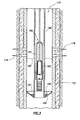
- Figure 1 is a fragmentary partially cross sectional view of a plunger lift production system in a hydrocarbon well showing an embodiment of the present invention
- Figure 2 is a fragmentary cross sectional view of the chemical dispenser of the present invention.
- Figure 3 is a fragmentary partially cross sectional view of a rod pump production system in a hydrocarbon well with an embodiment of the present invention.
- Figure 4 is a fragmentary cross section of a wellbore with a further embodiment of the present invention installed therein.
- the wellbore 10 has been cased with casing 12. Perforations 18 have been created in the casing 12 near the hydrocarbon bearing formation to allow such hydrocarbons out of the higher pressure formation into the lower pressure wellbore 10.
- Production tubing 20 is positioned within casing 12 to carry liquids to the surface.
- a plunger 25 is installed within production tubing 20 and typically resting on plunger stop 30.
- Plunger 25 while having a diameter that approximates the interior diameter of the production tubing 20, does not seal against the inside of the production tubing 20 and only rests on the plunger stop 30.
- a coiled spring 35 absorbs any shock of a rapidly descending plunger 25. Liquids slowly move around the heavier plunger 25 until a volume of liquid is in the production tubing above the plunger 25.
- the well is shut in by closing the wellbore 10 from any production. Pressure within the wellbore increases until the pressure within the wellbore is approximately the same as in the formation.
- the wellbore 10 is opened for production through the production tubing 10. Natural gas within the annulus out side the production tubing 20 decompresses by pushing liquid into the production tubing 20 and forcing the plunger 25 to the surface. When the plunger reaches the surface, it is carrying with it a slug of liquid ahead of it and sometimes more follows the plunger. Once the plunger reaches the surface, a plunger catcher catches and holds the plunger 25 out of the way of gas production into the meter and on to a natural gas gather system.
- the level of liquid in the wellbore 10 ranges from lower level 61 and is preferably maintained at or below level 62 so as not to block any of the perforations 18.
- a plunger lift arrangement such as shown, it is unlikely that liquid would exist much, if any, below the bottom end of the production string 20 and it is common for the gas pressure in the annulus to be higher than the gas pressure in the tubing so that while the liquid level may be at level 62 or below, the liquid level within the tubing may be at a level indicated at 63.
- the dispenser 40 is disposed within the liquid, continuously.
- plunger stop 30 includes a chemical dispenser 40 to liquids in the rat hole to continuously administer chemical treatment to the well.
- the chemical dispenser comprises a base 41, a cover 42 connected to the bottom end of bypass conduit 33 to maintain the base 41 and cover 42 into the liquid.
- the base 41 and cover 42 are entirely submerged in the liquid at all times once liquids have been produced from the formation.
- chemicals within the cover 42 are exposed to the liquid and allowed to disperse in the liquid.
- Slow release chemicals such as chemicals bound up in slow dissolving materials may provide extended presence of the chemicals in the liquid.
- the liquid is continuously dispensed as liquids continually enter the wellbore 10 and as liquids are periodically withdrawn from the wellbore.
- the liquids are stirred as the plunger is directed to the surface while the chemicals remain immersed in the liquid filled space in the rat hole.
- the chemical dispenser 40 is fairly simple having a base 41 with a cover attached by screw threads or other connecting arrangement. Chemical 45 is provided in the cover 42 and liquid enters and escapes through holes 44.
- a different embodiment of the chemical dispenser 140 having a porous or screen structure in the shape of an inverted umbrella is shown attached to the outside of production tubing 120 so that the liquid level is generally above the dispenser 140.
- the chemical 145 may be added to the well through the annulus within the casing 112 and outside the production tubing 120.
- a rod pump 150 draws liquids through a strainer nipple 155.
- Rod pump 150 operates in a conventional manner where liquids are drawn into and through the strainer nipple 155 by the plunger 152 moving up and down within barrel 151 and one way valves maintaining liquid flow up the production string 120.
- the liquid level is generally going to range between level 161 and 162 so that the dispense is substantially immersed in the liquid in the rat hole.
- the solid, slow release chemicals provided active protection for months and are believed to be likely to provide years of protection.
- the solid, slow release chemical in a continuously liquid wet position in the rat hole is more effective and far less costly.
- a chemical dispenser 140 is installed in a generally horizontal section of a well where liquids are being produced that are chemically prone to form scale, or corrosion or other production limiting problems.
- the dispenser 140 is shown as a hollow tube with screen covered ports 145 through which liquids may pass and come in contact with the solid installed inside the hollow tube of the dispenser 140.
- a liquid permeable container of most any sort will suffice. With the dispenser laying on the bottom of the horizontal section, if the liquids include both hydrocarbons and water which may form stratified layers, the chemical is most accessible to the water in which most of the problems may arise.
- slightly inclined or severely inclined portions of problematic wells may be provided with a dispenser 140 that is much smaller in diameter than the wellbore so as not to significantly interfere with liquid production while dispensing chemicals that may prolong high hydrocarbon recovery rates.
- the chemical is slowly dispensed into the fluids which are produced to the surface through equipment that is now less likely to suffer scale build-up or corrosion, etc.
- several laterals may extend from a common vertical well and each lateral may be provided with a dispenser 140 conveyed by wireline or coiled tubing tool and recovered for reloading when the chemical has been fully spent some many months or years later.
- the liquids are not as stirred as the liquids closer to the lower end of the production tubing.
- the active liquid interval where water is the continuous phase and where the water is likely to be regularly produced to the surface where the chemical dissolved in the water may be exposed to the surfaces vulnerable to the formation of precipitates such as scale or corrosion and reduce the buildup or actively reduce any buildup would be an optimal application of the present invention.
Landscapes
- Life Sciences & Earth Sciences (AREA)
- Mining & Mineral Resources (AREA)
- Geology (AREA)
- Engineering & Computer Science (AREA)
- Physics & Mathematics (AREA)
- Environmental & Geological Engineering (AREA)
- Fluid Mechanics (AREA)
- General Life Sciences & Earth Sciences (AREA)
- Geochemistry & Mineralogy (AREA)
- Chemical & Material Sciences (AREA)
- General Chemical & Material Sciences (AREA)
- Chemical Kinetics & Catalysis (AREA)
- Preventing Corrosion Or Incrustation Of Metals (AREA)
- Production Of Liquid Hydrocarbon Mixture For Refining Petroleum (AREA)
Applications Claiming Priority (2)
| Application Number | Priority Date | Filing Date | Title |
|---|---|---|---|
| US28575209P | 2009-12-11 | 2009-12-11 | |
| US12/900,218 US20110162841A1 (en) | 2009-12-11 | 2010-10-07 | Continuous Slow Dissolving Chemical Treatment for Oil and Gas Wells |
Publications (2)
| Publication Number | Publication Date |
|---|---|
| EP2336485A2 true EP2336485A2 (de) | 2011-06-22 |
| EP2336485A3 EP2336485A3 (de) | 2014-03-12 |
Family
ID=43533186
Family Applications (1)
| Application Number | Title | Priority Date | Filing Date |
|---|---|---|---|
| EP10190634.5A Withdrawn EP2336485A3 (de) | 2009-12-11 | 2010-11-10 | Durchgehende chemische Behandlung mit langsamer Auflösung für Öl- und Gasbohrlöcher |
Country Status (3)
| Country | Link |
|---|---|
| US (1) | US20110162841A1 (de) |
| EP (1) | EP2336485A3 (de) |
| WO (1) | WO2011071593A1 (de) |
Cited By (9)
| Publication number | Priority date | Publication date | Assignee | Title |
|---|---|---|---|---|
| RU172510U1 (ru) * | 2016-12-29 | 2017-07-11 | Общество с ограниченной ответственностью "КР-Петролеум" (ООО "КР-Петролеум") | Контейнер для подачи ингибитора в скважину |
| RU2698346C1 (ru) * | 2019-01-30 | 2019-08-26 | Сергей Владимирович Кривцов | Контейнер для подачи ингибитора в скважину |
| WO2020068309A1 (en) * | 2018-09-28 | 2020-04-02 | Baker Hughes, A Ge Company, Llc | Chemical deployment modular system and method of use |
| RU198809U1 (ru) * | 2019-12-27 | 2020-07-29 | Юрий Валентинович Данченко | Погружной контейнер |
| US11208588B1 (en) | 2020-11-05 | 2021-12-28 | Saudi Arabian Oil Company | Methods of dissolving gas hydrates |
| US11466195B2 (en) | 2020-11-05 | 2022-10-11 | Saudi Arabian Oil Company | Methods of dissolving gas hydrates |
| US11518924B2 (en) | 2020-11-05 | 2022-12-06 | Saudi Arabian Oil Company | Methods of dissolving gas hydrates |
| WO2026071904A1 (ru) * | 2024-09-25 | 2026-04-02 | Михаил Викторович НЕДЕЛЯЕВ | Погружной дозатор реагента - ингибитора |
| WO2026071903A1 (ru) * | 2024-09-25 | 2026-04-02 | Михаил Викторович НЕДЕЛЯЕВ | Погружной дозатор реагента - ингибитора |
Families Citing this family (11)
| Publication number | Priority date | Publication date | Assignee | Title |
|---|---|---|---|---|
| US9097093B1 (en) | 2012-01-06 | 2015-08-04 | Cavin B. Frost | Downhole chemical treatment assembly for use in a downhole wellbore |
| US8950491B2 (en) | 2012-01-06 | 2015-02-10 | Odessa Separator, Inc. | Downhole assembly for treating wellbore components, and method for treating a wellbore |
| US9097094B1 (en) | 2012-01-06 | 2015-08-04 | Cavin B. Frost | Method for chemically treating hydrocarbon fluid in a downhole wellbore |
| US10081758B2 (en) * | 2015-12-04 | 2018-09-25 | Ecolab Usa Inc. | Controlled release solid scale inhibitors |
| CA3024478A1 (en) | 2016-05-16 | 2017-11-23 | Ecolab Usa Inc. | Slow-release scale inhibiting compositions |
| AR110540A1 (es) | 2016-12-23 | 2019-04-10 | Ecolab Usa Inc | Inhibidores de incrustaciones sólidas de liberación controlada |
| CN109897615A (zh) * | 2019-04-26 | 2019-06-18 | 天津市玛特瑞科技有限公司 | 一种缓释镁合金完井工具助溶剂的制备方法 |
| US11293268B2 (en) | 2020-07-07 | 2022-04-05 | Saudi Arabian Oil Company | Downhole scale and corrosion mitigation |
| US20240141756A1 (en) * | 2022-11-02 | 2024-05-02 | Saudi Arabian Oil Company | Systems and methods to deploy a chemical inhibitor in an oil or gas well |
| US12378835B2 (en) | 2023-08-28 | 2025-08-05 | Saudi Arabian Oil Company | Method and device for downhole treating gas wells |
| CN117231167B (zh) * | 2023-11-09 | 2024-02-02 | 四川圣诺油气工程技术服务有限公司 | 酸液倾倒筒释放结构 |
Family Cites Families (12)
| Publication number | Priority date | Publication date | Assignee | Title |
|---|---|---|---|---|
| US2437475A (en) * | 1945-12-05 | 1948-03-09 | Sun Oil Co | Method of mitigating corrosion in wells |
| US4032457A (en) * | 1975-06-04 | 1977-06-28 | Fibredyne, Inc. | Plural stage filter cartridge wherein at least one stage comprises pulverized particulate material |
| US4291763A (en) * | 1979-11-05 | 1981-09-29 | Mortimer Singer | Dispenser for oil well treating chemicals |
| US4809778A (en) * | 1987-08-26 | 1989-03-07 | Marathon Oil Company | Oil well tool for in situ release of wellbore treatment fluid |
| US4790386A (en) * | 1988-02-01 | 1988-12-13 | Marathon Oil Company | Method and means for introducing treatment composition into a well bore |
| GB2284223B (en) * | 1993-11-27 | 1996-10-09 | Atomic Energy Authority Uk | Oil well treatment |
| US6209646B1 (en) * | 1999-04-21 | 2001-04-03 | Halliburton Energy Services, Inc. | Controlling the release of chemical additives in well treating fluids |
| US20040084186A1 (en) * | 2002-10-31 | 2004-05-06 | Allison David B. | Well treatment apparatus and method |
| AU2003288607A1 (en) * | 2002-12-19 | 2004-07-14 | Sofitech N.V. | Method for providing treatment chemicals in a subterranean well |
| US7451823B2 (en) * | 2003-07-30 | 2008-11-18 | Conocophillips Company | Well chemical treatment utilizing plunger lift delivery system with chemically improved plunger seal |
| US7195070B2 (en) * | 2004-07-15 | 2007-03-27 | Weatherford/Lamb, Inc. | Method and apparatus for downhole artificial lift system protection |
| US8162054B2 (en) * | 2009-08-24 | 2012-04-24 | Halliburton Energy Services Inc. | Methods and apparatuses for releasing a chemical into a well bore upon command |
-
2010
- 2010-10-07 US US12/900,218 patent/US20110162841A1/en not_active Abandoned
- 2010-10-08 WO PCT/US2010/052064 patent/WO2011071593A1/en not_active Ceased
- 2010-11-10 EP EP10190634.5A patent/EP2336485A3/de not_active Withdrawn
Non-Patent Citations (1)
| Title |
|---|
| None |
Cited By (10)
| Publication number | Priority date | Publication date | Assignee | Title |
|---|---|---|---|---|
| RU172510U1 (ru) * | 2016-12-29 | 2017-07-11 | Общество с ограниченной ответственностью "КР-Петролеум" (ООО "КР-Петролеум") | Контейнер для подачи ингибитора в скважину |
| WO2020068309A1 (en) * | 2018-09-28 | 2020-04-02 | Baker Hughes, A Ge Company, Llc | Chemical deployment modular system and method of use |
| US10837260B2 (en) | 2018-09-28 | 2020-11-17 | Baker Hughes, A Ge Company, Llc | Chemical deployment modular system and method of use |
| RU2698346C1 (ru) * | 2019-01-30 | 2019-08-26 | Сергей Владимирович Кривцов | Контейнер для подачи ингибитора в скважину |
| RU198809U1 (ru) * | 2019-12-27 | 2020-07-29 | Юрий Валентинович Данченко | Погружной контейнер |
| US11208588B1 (en) | 2020-11-05 | 2021-12-28 | Saudi Arabian Oil Company | Methods of dissolving gas hydrates |
| US11466195B2 (en) | 2020-11-05 | 2022-10-11 | Saudi Arabian Oil Company | Methods of dissolving gas hydrates |
| US11518924B2 (en) | 2020-11-05 | 2022-12-06 | Saudi Arabian Oil Company | Methods of dissolving gas hydrates |
| WO2026071904A1 (ru) * | 2024-09-25 | 2026-04-02 | Михаил Викторович НЕДЕЛЯЕВ | Погружной дозатор реагента - ингибитора |
| WO2026071903A1 (ru) * | 2024-09-25 | 2026-04-02 | Михаил Викторович НЕДЕЛЯЕВ | Погружной дозатор реагента - ингибитора |
Also Published As
| Publication number | Publication date |
|---|---|
| US20110162841A1 (en) | 2011-07-07 |
| EP2336485A3 (de) | 2014-03-12 |
| WO2011071593A1 (en) | 2011-06-16 |
Similar Documents
| Publication | Publication Date | Title |
|---|---|---|
| EP2336485A2 (de) | Durchgehende chemische Behandlung mit langsamer Auflösung für Öl- und Gasbohrlöcher | |
| CA3100655C (en) | Degradable metal body for sealing of shunt tubes | |
| US8245778B2 (en) | Fluid control apparatus and methods for production and injection wells | |
| RU2350738C2 (ru) | Способ и устройство для закачивания в скважину обрабатывающей текучей среды | |
| AU774008B2 (en) | Open hole zonal isolation and control | |
| US20040129428A1 (en) | Plunger lift deliquefying system for increased recovery from oil and gas wells | |
| CA2602878C (en) | Subterranean system and method for treating and producing oil | |
| US7493956B2 (en) | Subsurface safety valve with closure provided by the flowing medium | |
| RU2594235C2 (ru) | Способ одновременно-раздельной эксплуатации многопластовой залежи и устройство для реализации способа | |
| US20140263095A1 (en) | Chemical strainer | |
| Veeken et al. | Innovative use of capillary string for halite cleanout in sultanate of Oman | |
| AU2016433478B2 (en) | High flow screen system with degradable plugs | |
| RU2837493C1 (ru) | Способ глушения и/или вывода из эксплуатации нагнетательной скважины на ремонт | |
| US20180363429A1 (en) | Plunger lift assembly | |
| RU2168613C2 (ru) | Устройство для дозировки реагента в нефтедобывающую скважину | |
| RU2474674C1 (ru) | Способ очистки скважины | |
| Passucci et al. | Downhole injection of foaming agents with capillary string in a Mediterranean offshore gas well | |
| RU2735798C1 (ru) | Способ подачи растворителя аспо в скважину | |
| US20240392639A1 (en) | Side pocket mandrel for metered chemical injection | |
| CA3110266C (en) | Downhole device for hydrocarbon producing wells without conventional tubing | |
| Fairuzov et al. | Reducing the Risk of Plugging of Production Liner in Unconventional Wells | |
| BR102024003520A2 (pt) | Válvula elétrica para controle de incrustação de dispositivos de controle em uma coluna de produção em um poço e um método controle de incrustação e utilizando a referida válvula elétrica | |
| CA3227082A1 (en) | Methods for in-situ application of a coating agent to production tubing using a plunger lift system | |
| CN117948100A (zh) | 一种深水气井清喷阶段的水合物流动障碍预防方法及系统 | |
| CA2970569A1 (en) | Plunger lift assembly |
Legal Events
| Date | Code | Title | Description |
|---|---|---|---|
| PUAI | Public reference made under article 153(3) epc to a published international application that has entered the european phase |
Free format text: ORIGINAL CODE: 0009012 |
|
| AK | Designated contracting states |
Kind code of ref document: A2 Designated state(s): AL AT BE BG CH CY CZ DE DK EE ES FI FR GB GR HR HU IE IS IT LI LT LU LV MC MK MT NL NO PL PT RO RS SE SI SK SM TR |
|
| AX | Request for extension of the european patent |
Extension state: BA ME |
|
| PUAL | Search report despatched |
Free format text: ORIGINAL CODE: 0009013 |
|
| AK | Designated contracting states |
Kind code of ref document: A3 Designated state(s): AL AT BE BG CH CY CZ DE DK EE ES FI FR GB GR HR HU IE IS IT LI LT LU LV MC MK MT NL NO PL PT RO RS SE SI SK SM TR |
|
| AX | Request for extension of the european patent |
Extension state: BA ME |
|
| RIC1 | Information provided on ipc code assigned before grant |
Ipc: E21B 27/02 20060101ALI20140204BHEP Ipc: E21B 43/12 20060101ALI20140204BHEP Ipc: E21B 37/06 20060101AFI20140204BHEP |
|
| 17P | Request for examination filed |
Effective date: 20140912 |
|
| GRAP | Despatch of communication of intention to grant a patent |
Free format text: ORIGINAL CODE: EPIDOSNIGR1 |
|
| RIC1 | Information provided on ipc code assigned before grant |
Ipc: E21B 27/02 20060101ALI20160712BHEP Ipc: E21B 37/06 20060101AFI20160712BHEP Ipc: E21B 43/12 20060101ALI20160712BHEP |
|
| INTG | Intention to grant announced |
Effective date: 20160816 |
|
| GRAS | Grant fee paid |
Free format text: ORIGINAL CODE: EPIDOSNIGR3 |
|
| STAA | Information on the status of an ep patent application or granted ep patent |
Free format text: STATUS: THE APPLICATION HAS BEEN WITHDRAWN |
|
| 18W | Application withdrawn |
Effective date: 20170202 |