EP2335972A1 - Clip for holding a fastening elastic string - Google Patents
Clip for holding a fastening elastic string Download PDFInfo
- Publication number
- EP2335972A1 EP2335972A1 EP10252106A EP10252106A EP2335972A1 EP 2335972 A1 EP2335972 A1 EP 2335972A1 EP 10252106 A EP10252106 A EP 10252106A EP 10252106 A EP10252106 A EP 10252106A EP 2335972 A1 EP2335972 A1 EP 2335972A1
- Authority
- EP
- European Patent Office
- Prior art keywords
- elastic string
- fastening elastic
- clip
- main body
- clicks
- Prior art date
- Legal status (The legal status is an assumption and is not a legal conclusion. Google has not performed a legal analysis and makes no representation as to the accuracy of the status listed.)
- Withdrawn
Links
Images


Classifications
-
- B—PERFORMING OPERATIONS; TRANSPORTING
- B60—VEHICLES IN GENERAL
- B60N—SEATS SPECIALLY ADAPTED FOR VEHICLES; VEHICLE PASSENGER ACCOMMODATION NOT OTHERWISE PROVIDED FOR
- B60N2/00—Seats specially adapted for vehicles; Arrangement or mounting of seats in vehicles
- B60N2/58—Seat coverings
- B60N2/60—Removable protective coverings
- B60N2/6018—Removable protective coverings attachments thereof
- B60N2/6027—Removable protective coverings attachments thereof by hooks, staples, clips, snap fasteners or the like
-
- B—PERFORMING OPERATIONS; TRANSPORTING
- B60—VEHICLES IN GENERAL
- B60N—SEATS SPECIALLY ADAPTED FOR VEHICLES; VEHICLE PASSENGER ACCOMMODATION NOT OTHERWISE PROVIDED FOR
- B60N2/00—Seats specially adapted for vehicles; Arrangement or mounting of seats in vehicles
- B60N2/58—Seat coverings
- B60N2/5816—Seat coverings attachments thereof
- B60N2/5825—Seat coverings attachments thereof by hooks, staples, clips, snap fasteners or the like
-
- B—PERFORMING OPERATIONS; TRANSPORTING
- B60—VEHICLES IN GENERAL
- B60N—SEATS SPECIALLY ADAPTED FOR VEHICLES; VEHICLE PASSENGER ACCOMMODATION NOT OTHERWISE PROVIDED FOR
- B60N2/00—Seats specially adapted for vehicles; Arrangement or mounting of seats in vehicles
- B60N2/58—Seat coverings
- B60N2/5816—Seat coverings attachments thereof
- B60N2/585—Seat coverings attachments thereof by buckle passages
-
- B—PERFORMING OPERATIONS; TRANSPORTING
- B60—VEHICLES IN GENERAL
- B60N—SEATS SPECIALLY ADAPTED FOR VEHICLES; VEHICLE PASSENGER ACCOMMODATION NOT OTHERWISE PROVIDED FOR
- B60N2/00—Seats specially adapted for vehicles; Arrangement or mounting of seats in vehicles
- B60N2/58—Seat coverings
- B60N2/60—Removable protective coverings
- B60N2/6018—Removable protective coverings attachments thereof
- B60N2/6054—Removable protective coverings attachments thereof by buckle passages
-
- Y—GENERAL TAGGING OF NEW TECHNOLOGICAL DEVELOPMENTS; GENERAL TAGGING OF CROSS-SECTIONAL TECHNOLOGIES SPANNING OVER SEVERAL SECTIONS OF THE IPC; TECHNICAL SUBJECTS COVERED BY FORMER USPC CROSS-REFERENCE ART COLLECTIONS [XRACs] AND DIGESTS
- Y10—TECHNICAL SUBJECTS COVERED BY FORMER USPC
- Y10T—TECHNICAL SUBJECTS COVERED BY FORMER US CLASSIFICATION
- Y10T24/00—Buckles, buttons, clasps, etc.
- Y10T24/39—Cord and rope holders
Definitions
- This invention relates to a clip for holding a fastening elastic string, when attaching a seat back cover to a seat back main body.
- a bucket shaped seat is used in order to have good holding capacity of a seated person's body.
- This seat comprises a seat back main body and a seat back cover which is attached to the seat back main body.
- the seat back cover is attached to the seat back main body under tension by an elastic string (fastening elastic string) provided on a back surface thereof (for example, referred to Patent Document 1).
- the fastening elastic string is tied to the seat back main body with a ring shaped fixture called a "hog ring" (referred to Patent Document 2).
- the purpose of this invention is to conduct operation of tying a fastening elastic string used to attach a seat back cover to a seat back main body.
- this invention is, a clip made of plastic for holding a fastening elastic string, when attaching a seat back cover to a seat back main body of a vehicle with the fastening elastic string, in order to be used to hold the fastening elastic string to said seat back main body in a state that elastic tension occurs to the seat back main body, comprising;
- the elastic string When attaching the fastening elastic string to the clip of this invention, the elastic string is inserted to the groove of the clip while pulling the fastening elastic string in a longitudinal direction, and then the protrusion of the fastening elastic string is set on the stopper by relaxing the tension while maintaining that state.
- the protrusion of the fastening elastic string is set at the stopper of the groove of the clip with elasticity, so that displacement by vibration or secular change less likely occurs.
- At least one end of said groove it is desirable to form tapered inner surfaces, being distanced increasingly to an extending direction of the groove, to receive the protrusion of said fastening elastic string.
- This tapered inner surfaces act as guide or stopper for the protrusion of the fastening elastic string.
- Said stopper are positioned at back portion of said tapered inner surfaces of the groove, so that the protrusion of said fastening elastic string can be guided by said tapered inner surfaces and then set at said stopper.
- the stopper of said holding part set said protrusion formed on a middle portion of said fastening elastic string leaving a surplus length portion to end thereof, and said holding part is provided with constraining section to constrain the surplus length portion in a state that the protrusion is set at the stopper, as a portion being held by an operator for pulling operation of the fastening elastic string.
- the fastening elastic string is provided with the surplus length portion, and the operator can hold this surplus length portion to pull the fastening elastic string, and thus this operation is easy. Also, the surplus length portion of the fastening elastic string attached to the clip is constrained by the constraining section. This prevents the surplus length portion of the fastening elastic string from trailing down and being seen by a seated person of the vehicle, so as to achieve good appearance.
- Said locking part comprises at least one pair of elastically deformable clicks to be inserted to a fixing hole as the fixture formed on said seat back main body, and these clicks are touched to opening edges of said fixing hole so as to go through the opening edges while being elastically deformed to narrow distance therebetween, and then elastically restored as widening the distance, so as that these clicks are locked at the edges of the fixing hole.
- Fig.1 is a schematic view of a seat 100 for a vehicle.
- Fig. 2 is a plan view of a fastening elastic string 104.
- Fig.3 is an elevation view of a lower panel 103.
- Fig.4 is a perspective view of a clip 201 of the first embodiment .
- Fig. 5 is a sectional elevation view of the same.
- Fig.6 is a plain view of the same.
- Fig. 7 is a side view of the same.
- Fig.8 is a bottom view of the same.
- the seat 100 comprises a seat back main body 101 mainly made of plastic and a seat back cover 102 to be attached to the seat back main body 101.
- a lower panel 103 is attached at a lower back area of the seat back main body 101.
- the seat back cover 102 is held under tension applied by a clip for holding a fastening elastic string 201 (described simply as "clip 201" hereinafter) fixed to the lower panel 103, so as to be attached to the seat back main body 101.
- clip 201 fastening elastic string
- the fastening elastic string 104 will be explained. As shown in Fig. 2 , the fastening elastic string 104 is extendable in a longitudinal direction, having a circular section. A hook 2, which is ring-shaped and can be hooked to the seat back cover 102, is formed at one end portion of the elastic main body 1 of the fastening elastic string 104, and a protrusion 3, having a bigger diameter d2 than an outer diameter d1 of the elastic main body 1 (d2>d1), is provided near the other end (which is a side to be fixed to the clip 102) . Also, ahead of the protrusion 3, a grip 4, which allows an operator to pull the fastening elastic string 104 easily in a longitudinal direction, is provided extendedly from the protrusion 3.
- An outer diameter of the grip 4 is the same as the outer diameter d1 of the elastic main body 1, and the maximum outer diameter d2 of the protrusion 3 is approximately twice larger than the outer diameter d1 of the elastic main body 1.
- the protrusion 3 of this embodiment has a combined shape of a first tapered outer circumferential surface 3a, which is conically trapezoidal shaped and provided extendedly so as to have a predetermined inclined angle ⁇ 1 from the elastic main body 1 and its outer diameter d1 to increase continuously, a maximum outer diameter portion 3b provided continuously from the first tapered outer circumferential surface 3a, and a second tapered outer circumferential surface 3c, which is conically trapezoidal shaped and provided extendedly so as to have a predetermined inclined angle ⁇ 2 from the maximum outer diameter portion 3b to the grip 4 and its outer diameter d1 to decrease continuously.
- two fixing holes 5, which respectively have predetermine distances vertically, are provided respectively near both ends in a width direction of the lower panel 103.
- the clips 201 of the embodiment of this invention are fixed to these fixing holes 5 (it will be explained later).
- the fixing holes 5 have the same size and placement, and thus the fixing holes 5 on one side (the left side from the view of the Fig.3 ) will be explained in the descriptions.
- the fixing holes 5 provided on the lower panel 103 are initially for placing hog rings. Further, each hole provided around the fixing holes 5 is for lacing wire harnesses.
- Each fixing hole 5 is rectangular shaped, and the two fixing holes 5 are provided vertically in parallel on the lower panel 103, having a predetermined distance.
- a bridge 6 is formed between the two fixing holes 5. It will describe an inner width of the fixing hole 5 as W1, an inner height of the fixing hole 5 as L1 and a height of the bridge 6 as L2 hereinafter.
- the clip 201 of the first embodiment of this invention will be explained, referring to Figs.4 to Fig.8 .
- the clip 201 is formed by injection molding of thermoplastic resin (e.g. polyacetal) .
- a holding part 7 is formed to insert and hold the elastic main body 1 of the fastening elastic string 104 on an upper portion of the clip 201, and similarly a locking part 8 is formed to be inserted and locked to the fixing hole 5 of the lower panel 103 on a lower portion of the clip 201.
- it describes a horizontal direction on the view of Fig.5 as "width direction P", an intersecting direction with the width direction P on a horizontal plane (orthogonal direction in this embodiment's case) as "depth direction Q" shown in Fig.7 .
- a groove 9 is formed, having a predetermined width W2, on the holding part 7 from its upper end surface down ( to the side of the locking part 8 provided) to an above surface 8a of the locking part 8.
- the above surface 8a of the locking part 8 is the same as a bottom surface of the groove 9.
- a pair of walls 11 is vertically arranged in the width direction P, being opposed to each other.
- a width W2 of the groove 9 is approximately the same as the outer diameter d1 of the elastic main body 1 of the fastening elastic string 104 (it will be smaller than the outer diameter d1 of the elastic main body 1, when the fastening elastic string 104 is pulled), and a depth D of the groove 9 is slightly greater than the maximum outer diameter d2 of the protrusion 3 of the fastening elastic string 104.
- tapered inner surfaces 12 are formed symmetrically to a midpoint in a longitudinal direction of the groove 9, being distanced increasingly in an extending direction of the groove 9. These tapered inner surfaces 12 are guides to help the fastening elastic string 104 to enter the groove 9.
- a pair of stoppers 11b to contact directly and set the protrusion 3 of the fastening elastic string 104 is formed to be right to the groove direction and also to project inwardly.
- the protrusion 3 of the fastening elastic string 104 is inserted to the groove 9 as going underneath the projecting portions 11a, and then the protrusion 3 touches the stoppers 11b so as to be held.
- the distance between the stoppers 11b is the same as the width W2 of the groove 9, and approximately the same as the outer diameter d1 of the elastic main body 1 of the fastening elastic string 104.
- constraining sections 13 are vertically arranged respectively. These constraining sections 13 are arranged in a state of being standing from the above surface 8a of the locking part 8.
- an upper space 14 having a predetermined width is formed between the paired walls 11 and the respective constraining sections 13.
- end portions (upper end portions) of the respective constraining sections are bended obliquely downward to the groove 9 side, so as to form hedges 13a at these bended portions.
- the grip 4 which is a surplus portion of the fastening elastic string 104, is placed at the upper space 14 and held by the hedges 13a. This prevents the grip 4 of the fastening elastic string 104 fixed by the clip 201 from trailing down.
- the locking part 8 of the clip 201 is divided into two, and comprises first and second locking main bodies 15, 16.
- the respective locking main bodies 15, 16 are arranged opposedly, so as to be bilaterally symmetrical with a first center line CL1 which divides the width W2 of the groove 9 of the holding part 7 into two, and also to be anteroposteriorly symmetrical with a second center line CL2 (a theoretical center line along the width direction P) which divides a depth length L3 of the clip 201 into two.
- configurations of the first locking main body 15 and the second locking main body 16 are the same except being symmetrical, and thus the descriptions only explains the first locking main body 15.
- the first locking main body 15 is provided extendedly on the lower side of the holding part 7, having an end surface (front surface) thereof in the depth direction Q as the same as the end surface of the holding part 7.
- width W3 of the first locking main body 15 is slightly smaller than width W4 of the holding part 7 (W3 ⁇ W4), and a stepped surface 18 is formed between the holding part 7 and the locking main body 15.
- respective clicks 19 are formed on upper portions of the both ends (side surface walls 15a) in the width direction P of the first locking main body 15.
- the click 19 is formed by being cut off with a U-shaped cut-off groove 22 shown in Fig.7 except a lower end (base end section 21) of the click 19 on the side surface wall 15a of the first locking main body 15. This allows the click 19 to turn freely (elastically deformable) to the arrow 23 direction (shown in Fig.5 ) with the connected section (base end section) to the side surface wall 15a as a supporting point.
- the click 19 is triangle shaped in section, and its apex 24 projects from the side surface wall 15a of the first locking main body 15 to outer surfaces of the pair of the constraining sections. Also, the click 19 is formed with a lower inclined surface 25 reaching to the base end section 21 in a region lower than the apex 24, and similarly an upper inclined surface 26 and a perpendicular surface 27 in a upper region. Regarding the click 19, a inclined angle of the lower inclined surface 25 to the height direction (perpendicular direction) is shallower than a inclined angle of the upper inclined surface 26.
- the clip 201 is attached by inserting the first and second locking main bodies 15, 16 of the locking part 8 to the two fixing holes 5 of the lower panel 103 shown in Fig.3 .
- the first and second locking main bodies 15, 16 of the clip 201 are inserted to the fixing holes 5 over the bridge 6 of the lower panel 103.
- the width W3 of the first locking main body 15 of the clip 201 is slightly smaller than the inner width W1 of the fixing holes 5 of the lower panel 103
- the width W4 of the holding part 7 of the clip 201 is slightly greater than the inner width W1 of the fixing hole 5 (W3 ⁇ W1 ⁇ W4) .
- references 28 on Fig.8 are removed holes provided on the respective locking main bodies 15, 16 for weight-saving of the clip 201.
- the ring-shaped hook 2 on Fig. 2 of the fastening elastic string 104 is hooked preliminarily on a back portion of the seat back cover 102.
- an operator mounts the elastic main body 1 of the fastening elastic string 104 on an attaching groove (not shown) of the seat back main body 101, and deliver the other end (the end of the side provided with the protrusion 3) of the fastening elastic string 104 underneath the bottom side of the seat back main body 101 so as to be pulled out to the back side.
- the lower panel 103 is attached at a lower end on the back side of the seat back main body 101.
- the clip 201 is fixed to the two fixing holes 5 provided on this lower panel 103.
- the first and second locking main bodies 15, 16 provided on the locking part 8 of the clip 201 are inserted to the two fixing holes 5 over the bridge 6.
- the distance L4 of the lower space 17 is slightly greater than the height L2 on Fig. 3 of the bridge 6 of the lower panel 103, and thus the first and second locking main bodies 15, 16 can be inserted to the fixing holes 5 over the bridge 6.
- the height L1 on Fig.3 of the respective fixing holes 5 is greater than thickness L5 on Fig.7 , 8 of the respective locking main bodies 15, 16 of the clip 201, so that it would not cause any troubles to inserting the respective locking main bodies 15, 16 to the two fixing holes 5.
- the clip 201 makes the perpendicular surfaces 27 of the clicks 19 to be placed opposedly to the fixing holes, and also the stepped surface 18 of the holding part 7 to touch the surface of the lower panel 103, and then stops.
- the holding part 7 of the clip 201 projects from the surface of the lower panel 103.
- the clicks 19 of the respective locking main bodies 15, 16 of the clip 201 are locked to the fixing holes 5, so that the clip 201 cannot be pulled out.
- the inclined angle of the upper inclined surface 26 is steep, so as to prevent the clicks 19 from being pulled out even further.
- the thicknesses L5 of the first and second locking main bodies are the same, and also these are arranged symmetrical to the second center line CL2 of the clip 201. Because of this, when the respective locking main bodies 15, 16 of the clip 201 are inserted to the fixing holes 5 of the lower panel 103, they can be inserted whichever the side up. Also, as shown in Fig.6 , regarding the holding part 7 of the clip 201, the groove 9 is arranged symmetrical to the first center line CL1. Because of this, regardless being attached whichever the side up, the position of the groove 9 is always constant. That means, the operator does not have to pay attention to the up or down direction when attaching the clip 201.
- the respective locking main bodies 15, 16 of the clip 201 are fixed over the bridges 6 of the fixing holes. Because of this, when trying to attach the clip mistakenly crisscross, the respective locking main bodies 15, 16 of the clips 201 and the bridges 6 interfere, so as to unable to attach it. As a result, improper attachment would not occur.
- the protrusion 3 is disposed above the holding part 7 of the clip 201.
- the seat back cover 102 clings closely to the seat back main body 101 (referred to Fig.1 ) .
- the elastic main body 1 of the fastening elastic string 104 is inserted to the groove 9 of the holding part 7 of the clip 201.
- the tapered inner surfaces 12 on lower sides on Fig.11 are guides to lead the fastening elastic string 104.
- the protrusion 3 stops in a stated of the tapered outer circumferential surface 3a shown in Fig.2 being pushed into a gap between the stoppers 11b. Also, the maximum outer diameter 3b of the protrusion 3 is underneath the projecting portions 11a shown in Fig.5 , so that there is no possibility that the fastening elastic string 104 would be pulled out upwardly in a view of Fig.5 .
- the grip 4 which is the surplus portion, is disposed at the space 14 (shown in Fig. 5 ) between the walls 11 and the constraining sections .13, and held by the hedges 13a the constraining sections 13.
- Tension force F shown in Fig. 12 of the fastening elastic string 104 acts on the clip 201 attached to two fixing holes 5 provided on the lower panel 3, as shown in Fig. 7 , the bridges 6 of the lower panel 103 are disposed at the lower space 17 between the respective locking main bodies 15, 16, and the bridges 6 exercise a stopper function, and the bridges 6 receive the tension force F of the fastening elastic string 104 acting on the clip 201.
- the clip 201 of this embodiment is provided with two locking main bodies 15, 16 on the locking part 8, in order to be attached with use of two fixing holes 5 provided on the existing lower panel 103.However supposing a case of having one fixing hole 5, or a case of fixing the clip 201 to any one of the two fixing hole 5, as shown in Fig.13 , a locking main body 31 may be formed on the locking part 8. Regarding a clip 202 of the embodiment (the second embodiment) of Fig. 13 , the length L3 of the locking part 8 of the clip 202 is set according to the height L1 of the fixing hole 5 shown in Fig. 7 (so as to be slightly shorter than the height L1 of the fixing hole 5) .
- this clip 202 it is desirable to have the locking part 8 to be rectangular shaped in a planer view, having the length L3 and the width W3 of the locking part 8 (locking main body 31) different, so as to prevent the operator from mistaking crisscross during attachment. Also, regarding other parts, it is the same as the clip 201 of the first embodiment shown in Figs.4 to 8 , thus the explanations will be diverted with the same parts referred to the same references, and the explanation in details will be omitted.
- Figs.14 to 20 show another embodiment.
- Fig.14 shows an example that the stopper 11b has a conically trapezoidal shaped inner surface 11c corresponding to the first tapered circumferential surface 3a of the protrusion 3 of a fastening elastic string 104
- Fig. 15 shows an example that a tapered inner surface 12 is formed only on side of the groove 9 (the side having the protrusion to be inserted)
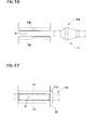
- Fig. 16 is an example that there is no tapered inner surface 12 at both ends of the groove 9
- Fig.17 is an example that a protrusion 32 (e.g. a mere large diameter portion, not being tapered) of a fastening elastic string 105 is set at one side surface of the groove 9 as a stopper 11d.
- a protrusion 32 e.g. a mere large diameter portion, not being tapered
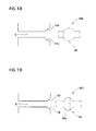
- Fig.18 shows an example that a spherical concave surface fitted to a protrusion 33 (spherical in this case) of a fastening elastic string 106 is formed on one end surface of the groove 9, and as a stopper 11e the protrusion 33 is set thereon
- Fig.19 is an example that if a protrusion 34 a fastening elastic string 107 has a conically trapezoidal tapered circumferential surface 34a, a stopper 11f corresponding the tapered circumferential surface 34a is formed on one side surface of the groove 9, and
- Fig.20 is an example that a groove 35 is refractive nonlinear instead of linear , and a fastening elastic string 107 is inserted thereto, and a protrusion 34 thereof is set at a stopper11g provided on a end portion or center portion of the groove 35.
Abstract
The purpose of this invention is to easily conduct operation to fix a fastening elastic string in order to attach a seat back cover to a seat back main body.
The means to achieve the purpose is to form a clip (201) comprising a holding part (7) provided with a groove (9) to hold a fastening elastic string (104) and a locking part (8) provided with first and second locking bodies (15, 16) in order to be locked to a fixing hole (5) of a lower panel (103), then to insert the fastening elastic string (104) to the groove (9) of the clip (201) while pulling thereof, and then to set a protrusion (3) of the fastening elastic string (104) to stopper (11b) of the groove (9) with elasticity in the shrinking direction.
Description
- This application claims the priority of Japanese Patent Application No.
2009-285313 filed on December 16, 2009 - This invention relates to a clip for holding a fastening elastic string, when attaching a seat back cover to a seat back main body.
- For a vehicle (such as a car), a bucket shaped seat is used in order to have good holding capacity of a seated person's body. This seat comprises a seat back main body and a seat back cover which is attached to the seat back main body. Also, the seat back cover is attached to the seat back main body under tension by an elastic string (fastening elastic string) provided on a back surface thereof (for example, referred to Patent Document 1). The fastening elastic string is tied to the seat back main body with a ring shaped fixture called a "hog ring" (referred to Patent Document 2).
- However, the operation of tying a fastening elastic string to a hog ring is complicated and it is a reason of preventing work efficiency improvement.
-
- [Patent Document 1] Japanese Laid-Open Patent Publication No.
H7-59962 - [Patent Document 2] Japanese Laid-Open Patent Publication No.
2003-275067 - Considering the above situations, the purpose of this invention is to conduct operation of tying a fastening elastic string used to attach a seat back cover to a seat back main body.
- In order to achieve the above purpose, this invention is,
a clip made of plastic for holding a fastening elastic string, when attaching a seat back cover to a seat back main body of a vehicle with the fastening elastic string, in order to be used to hold the fastening elastic string to said seat back main body in a state that elastic tension occurs to the seat back main body,
comprising; - a locking part to be locked to a fixture formed on said seat back main body; and
- a holding part including;
- a groove formed integrally with the locking part, and in order to hold a protrusion formed protrudingly on a part of said fastening elastic string so as to protrude in a thickness direction thereof, to insert the fastening elastic string in a state of being under elastic tension thereof; and
- stopper formed on a part of said groove to set said protrusion by elasticity in a shrinking direction of the fastening elastic string in a state of tension to said fastening elastic string being relaxed.
- When attaching the fastening elastic string to the clip of this invention, the elastic string is inserted to the groove of the clip while pulling the fastening elastic string in a longitudinal direction, and then the protrusion of the fastening elastic string is set on the stopper by relaxing the tension while maintaining that state. This allows the fastening elastic string to be attached to the clip in a retained state. All an operator needs to do is to pull the fastening elastic string in a longitudinal direction, to insert the elastic string to the groove of the clip, and then to relax that tension, and thus this attaching operation is extremely easy. Also, the protrusion of the fastening elastic string is set at the stopper of the groove of the clip with elasticity, so that displacement by vibration or secular change less likely occurs.
- At least one end of said groove, it is desirable to form tapered inner surfaces, being distanced increasingly to an extending direction of the groove, to receive the protrusion of said fastening elastic string. This tapered inner surfaces act as guide or stopper for the protrusion of the fastening elastic string.
- Said stopper are positioned at back portion of said tapered inner surfaces of the groove, so that the protrusion of said fastening elastic string can be guided by said tapered inner surfaces and then set at said stopper.
- The stopper of said holding part set said protrusion formed on a middle portion of said fastening elastic string leaving a surplus length portion to end thereof,
and said holding part is provided with constraining section to constrain the surplus length portion in a state that the protrusion is set at the stopper, as a portion being held by an operator for pulling operation of the fastening elastic string. - The fastening elastic string is provided with the surplus length portion, and the operator can hold this surplus length portion to pull the fastening elastic string, and thus this operation is easy. Also, the surplus length portion of the fastening elastic string attached to the clip is constrained by the constraining section. This prevents the surplus length portion of the fastening elastic string from trailing down and being seen by a seated person of the vehicle, so as to achieve good appearance.
- Said locking part comprises at least one pair of elastically deformable clicks to be inserted to a fixing hole as the fixture formed on said seat back main body, and
these clicks are touched to opening edges of said fixing hole so as to go through the opening edges while being elastically deformed to narrow distance therebetween, and then elastically restored as widening the distance, so as that these clicks are locked at the edges of the fixing hole. -
-
Fig.1 is a schematic view of aseat 100 for a vehicle. -
Fig.2 is a plan view of a fasteningelastic string 104. -
Fig.3 is an elevation view of alower panel 103. -
Fig.4 is a perspective view of aclip 201 of the first embodiment. -
Fig.5 is a sectional elevation view of the same. -
Fig.6 is a plan view of the same. -
Fig.7 is a side view of the same. -
Fig.8 is a bottom view of the same. -
Fig. 9A is an illustration for function ofclicks 19 when fixing aclip 201 to afixing hole 5. -
Fig.9B is an illustration for function of the same. -
Fig.9C is an illustration for function of the same. -
Fig.10 is an illustration for function in a state of inserting a fasteningelastic string 104 to agroove 9 of aclip 201. -
Fig.11 is a plan view in a state ofFig.10 . -
Fig. 12 is a plan view in a state that a fasteningelastic string 104 is fixed to aclip 201. -
Fig. 13 is a perspective view of aclip 202 of the second embodiment. -
Fig.14 is a view showing the modified example 1. -
Fig.15 is a view showing the modified example 2. -
Fig.16 is a view showing the modified example 3. -
Fig.17 is a view showing the modified example 4. -
Fig.18 is a view showing the modified example 5. -
Fig.19 is a view showing the modified example 6. -
Fig.20 is a view showing the modified example 7. - Hereinafter, embodiments of this invention will be explained in details.
Fig.1 is a schematic view of aseat 100 for a vehicle.Fig. 2 is a plan view of a fasteningelastic string 104.Fig.3 is an elevation view of alower panel 103.Fig.4 is a perspective view of aclip 201 of the first embodiment .Fig. 5 is a sectional elevation view of the same.Fig.6 is a plain view of the same.Fig. 7 is a side view of the same.Fig.8 is a bottom view of the same. - Firstly, configuration of a
seat 100 will be explained briefly. As shown inFig. 1 , theseat 100 comprises a seat backmain body 101 mainly made of plastic and a seatback cover 102 to be attached to the seat backmain body 101. Alower panel 103 is attached at a lower back area of the seat backmain body 101. The seatback cover 102 is held under tension applied by a clip for holding a fastening elastic string 201 (described simply as "clip 201" hereinafter) fixed to thelower panel 103, so as to be attached to the seat backmain body 101. - The fastening
elastic string 104 will be explained. As shown inFig. 2 , the fasteningelastic string 104 is extendable in a longitudinal direction, having a circular section. Ahook 2, which is ring-shaped and can be hooked to the seat backcover 102, is formed at one end portion of the elasticmain body 1 of the fasteningelastic string 104, and aprotrusion 3, having a bigger diameter d2 than an outer diameter d1 of the elastic main body 1 (d2>d1), is provided near the other end (which is a side to be fixed to the clip 102) . Also, ahead of theprotrusion 3, agrip 4, which allows an operator to pull the fasteningelastic string 104 easily in a longitudinal direction, is provided extendedly from theprotrusion 3. An outer diameter of thegrip 4 is the same as the outer diameter d1 of the elasticmain body 1, and the maximum outer diameter d2 of theprotrusion 3 is approximately twice larger than the outer diameter d1 of the elasticmain body 1. Theprotrusion 3 of this embodiment has a combined shape of a first tapered outercircumferential surface 3a, which is conically trapezoidal shaped and provided extendedly so as to have a predetermined inclined angle θ1 from the elasticmain body 1 and its outer diameter d1 to increase continuously, a maximumouter diameter portion 3b provided continuously from the first tapered outercircumferential surface 3a, and a second tapered outercircumferential surface 3c, which is conically trapezoidal shaped and provided extendedly so as to have a predetermined inclined angle θ2 from the maximumouter diameter portion 3b to thegrip 4 and its outer diameter d1 to decrease continuously. - As shown in
Fig.3 , two fixingholes 5, which respectively have predetermine distances vertically, are provided respectively near both ends in a width direction of thelower panel 103. Theclips 201 of the embodiment of this invention are fixed to these fixing holes 5 (it will be explained later). The fixing holes 5 have the same size and placement, and thus the fixing holes 5 on one side (the left side from the view of theFig.3 ) will be explained in the descriptions. Also, the fixingholes 5 provided on thelower panel 103 are initially for placing hog rings. Further, each hole provided around the fixing holes 5 is for lacing wire harnesses. - Each fixing
hole 5 is rectangular shaped, and the two fixingholes 5 are provided vertically in parallel on thelower panel 103, having a predetermined distance. Herewith, abridge 6 is formed between the two fixingholes 5. It will describe an inner width of the fixinghole 5 as W1, an inner height of the fixinghole 5 as L1 and a height of thebridge 6 as L2 hereinafter. - Next, the
clip 201 of the first embodiment of this invention will be explained, referring toFigs.4 to Fig.8 . Theclip 201 is formed by injection molding of thermoplastic resin (e.g. polyacetal) . A holdingpart 7 is formed to insert and hold the elasticmain body 1 of the fasteningelastic string 104 on an upper portion of theclip 201, and similarly a lockingpart 8 is formed to be inserted and locked to the fixinghole 5 of thelower panel 103 on a lower portion of theclip 201. Here, it describes a horizontal direction on the view ofFig.5 as "width direction P", an intersecting direction with the width direction P on a horizontal plane (orthogonal direction in this embodiment's case) as "depth direction Q" shown inFig.7 . - As shown in
Fig. 5 , agroove 9 is formed, having a predetermined width W2, on the holdingpart 7 from its upper end surface down ( to the side of the lockingpart 8 provided) to anabove surface 8a of the lockingpart 8. Theabove surface 8a of the lockingpart 8 is the same as a bottom surface of thegroove 9. On the holdingpart 7, a pair ofwalls 11 is vertically arranged in the width direction P, being opposed to each other. A width W2 of thegroove 9 is approximately the same as the outer diameter d1 of the elasticmain body 1 of the fastening elastic string 104 (it will be smaller than the outer diameter d1 of the elasticmain body 1, when the fasteningelastic string 104 is pulled), and a depth D of thegroove 9 is slightly greater than the maximum outer diameter d2 of theprotrusion 3 of the fasteningelastic string 104. As shown inFig. 6 , at both end portions in the depth direction Q of the pair of thewalls 11, taperedinner surfaces 12 are formed symmetrically to a midpoint in a longitudinal direction of thegroove 9, being distanced increasingly in an extending direction of thegroove 9. These taperedinner surfaces 12 are guides to help the fasteningelastic string 104 to enter thegroove 9. The upper end portions of therespective walls 11, which form thegroove 9 and opposing to each other, project inwardly to each other, so as to form projectingportions 11a to cover space of thegroove 9 partly from above. Further, at back portions in a groove direction of the taperedinner surfaces 12, a pair ofstoppers 11b to contact directly and set theprotrusion 3 of the fasteningelastic string 104 is formed to be right to the groove direction and also to project inwardly. Theprotrusion 3 of the fasteningelastic string 104 is inserted to thegroove 9 as going underneath the projectingportions 11a, and then theprotrusion 3 touches thestoppers 11b so as to be held. The distance between thestoppers 11b is the same as the width W2 of thegroove 9, and approximately the same as the outer diameter d1 of the elasticmain body 1 of the fasteningelastic string 104. - As shown in
Figs.6 and4 , at outer sides (back regions) and approximately central portions in the depth direction Q of the pairedwalls 11, constrainingsections 13 are vertically arranged respectively. These constrainingsections 13 are arranged in a state of being standing from theabove surface 8a of the lockingpart 8. Herewith, anupper space 14 having a predetermined width is formed between the pairedwalls 11 and the respective constrainingsections 13. Also, end portions (upper end portions) of the respective constraining sections are bended obliquely downward to thegroove 9 side, so as to formhedges 13a at these bended portions. As explained later, when the fasteningelastic string 104 is attached to theclip 201, thegrip 4, which is a surplus portion of the fasteningelastic string 104, is placed at theupper space 14 and held by thehedges 13a. This prevents thegrip 4 of the fasteningelastic string 104 fixed by theclip 201 from trailing down. - Next, the locking
part 8 of theclip 201 will be explained. As shown inFigs.4 ,7 and8 , the lockingpart 8 of theclip 201 of this embodiment is divided into two, and comprises first and second lockingmain bodies Figs. 6 and8 , the respective lockingmain bodies groove 9 of the holdingpart 7 into two, and also to be anteroposteriorly symmetrical with a second center line CL2 (a theoretical center line along the width direction P) which divides a depth length L3 of theclip 201 into two. As shown inFig.7 , alower space 17, being groove shaped, is formed between the first lockingmain body 15 and the second lockingmain body 16, and a distance thereof L4 is slightly greater than the height L2 of thebridge 6 of thelower panel 103 shown inFig. 3 . Here, configurations of the first lockingmain body 15 and the second lockingmain body 16 are the same except being symmetrical, and thus the descriptions only explains the first lockingmain body 15. - As shown in
Figs. 4 and7 , the first lockingmain body 15 is provided extendedly on the lower side of the holdingpart 7, having an end surface (front surface) thereof in the depth direction Q as the same as the end surface of the holdingpart 7. As shown inFig.5 , width W3 of the first lockingmain body 15 is slightly smaller than width W4 of the holding part 7 (W3<W4), and a steppedsurface 18 is formed between the holdingpart 7 and the lockingmain body 15. - As shown in
Fig.5 ,respective clicks 19 are formed on upper portions of the both ends (side surface walls 15a) in the width direction P of the first lockingmain body 15. Theclick 19 is formed by being cut off with a U-shaped cut-offgroove 22 shown inFig.7 except a lower end (base end section 21) of theclick 19 on theside surface wall 15a of the first lockingmain body 15. This allows theclick 19 to turn freely (elastically deformable) to thearrow 23 direction (shown inFig.5 ) with the connected section (base end section) to theside surface wall 15a as a supporting point. Theclick 19 is triangle shaped in section, and its apex 24 projects from theside surface wall 15a of the first lockingmain body 15 to outer surfaces of the pair of the constraining sections. Also, theclick 19 is formed with a lowerinclined surface 25 reaching to thebase end section 21 in a region lower than the apex 24, and similarly an upperinclined surface 26 and aperpendicular surface 27 in a upper region. Regarding theclick 19, a inclined angle of the lowerinclined surface 25 to the height direction (perpendicular direction) is shallower than a inclined angle of the upperinclined surface 26. - As shown in
Figs.7 and8 , theclip 201 is attached by inserting the first and second lockingmain bodies part 8 to the two fixingholes 5 of thelower panel 103 shown inFig.3 . Here, the first and second lockingmain bodies clip 201 are inserted to the fixingholes 5 over thebridge 6 of thelower panel 103. Because of this, the width W3 of the first lockingmain body 15 of theclip 201 is slightly smaller than the inner width W1 of the fixingholes 5 of thelower panel 103, and the width W4 of the holdingpart 7 of theclip 201 is slightly greater than the inner width W1 of the fixing hole 5 (W3<W1<W4) . This allows the respective lockingmain bodies clip 201 to be inserted to the fixing holes 5, and also, as shown inFig. 5 , when theclick 19 is elastically deformed and then pass the fixing hole, the steppedsurface 18 of the holdingpart 7 and the locking part 8 (that are the first and second lockingpart 15, 16) of theclip 201 touches a surface of thelower panel 103, so as to disable theclip 201 to be inserted further. Also, the first and second lockingmain bodies clip 201 reaches over the bridges 6 (holds thebridges 6 bilaterally), and thus the clip is not misaligned vertically of the fixing holes. As a result, theclip 201 is attached to the fixing holes 5 of thelower panel 103. That is to say, the position of the first and second lockingmain bodies holes 5 are restricted by thebridges 6. Also, references 28 onFig.8 are removed holes provided on the respective lockingmain bodies clip 201. - Function of the
clip 201 of this embodiment will be explained. As shown inFig.1 , the ring-shapedhook 2 onFig. 2 of the fasteningelastic string 104 is hooked preliminarily on a back portion of the seat backcover 102. When attaching the seat backcover 102 to the seat backmain body 101, an operator mounts the elasticmain body 1 of the fasteningelastic string 104 on an attaching groove (not shown) of the seat backmain body 101, and deliver the other end (the end of the side provided with the protrusion 3) of the fasteningelastic string 104 underneath the bottom side of the seat backmain body 101 so as to be pulled out to the back side. - The
lower panel 103 is attached at a lower end on the back side of the seat backmain body 101. Theclip 201 is fixed to the two fixingholes 5 provided on thislower panel 103. When doing so, the first and second lockingmain bodies part 8 of the clip 201are inserted to the two fixingholes 5 over thebridge 6. As shown inFigs. 7 and8 , regarding the lockingpart 8 of theclip 201, the distance L4 of thelower space 17 is slightly greater than the height L2 onFig. 3 of thebridge 6 of thelower panel 103, and thus the first and second lockingmain bodies holes 5 over thebridge 6. Also, the height L1 onFig.3 of the respective fixingholes 5 is greater than thickness L5 onFig.7 ,8 of the respective lockingmain bodies clip 201, so that it would not cause any troubles to inserting the respective lockingmain bodies holes 5. - Function of the
click 19 then will be explained, referring toFigs . 9A to 9C . As shown inFig. 9A , when the first and second lockingmain bodies clip 201 are inserted to the fixing holes 5, the lowerinclined surfaces 25 of theseclicks 19 touches the inner wall surfaces of the fixing holes 5. When inserting theclip 201 further in this state, as shown inFig.9B , the clicks turns to an inward direction shown with the arrow 23 (a direction which makes distance between theseapexes 24 shorter), having theirbase end sections 21 as supporting points so as to be elastically deformed. This allows the lockingpart 8 of the clip to be inserted to the fixing holes 5. The inclined angle of the lowerinclined surface 25 of theclick 9 is shallow, and thus the operator can easily insert theclip 201 to the fixing holes 5. - When the apex 24 of the
click 19 passes the inner wall of the fixinghole 5, as shown inFig.9C , theclick 19 turns to an opposite direction (outer direction shown with the arrow 23) so as to be elastically restored, the respective lockingmain bodies clip 201 being inserted while the upperinclined surface 26 of theclick 26 being touched the inner wall of the fixing hole. This makes the distance between theapexes 24 of theclicks 19 wider. This distance is greater than the inner width W1 of the fixinghole 5 shown inFig.5 , and thus the lockingpart 8 of theclip 201 has been inserted to the fixing holes cannot be pulled out. The inclined angle of the upperinclined surface 26 is steeper than the inclined angle of the lowerinclined surface 25, and thus theclip 201 is rapidly restored elastically. Then, theclip 201 makes theperpendicular surfaces 27 of theclicks 19 to be placed opposedly to the fixing holes, and also the steppedsurface 18 of the holdingpart 7 to touch the surface of thelower panel 103, and then stops. In this state, the holdingpart 7 of theclip 201 projects from the surface of thelower panel 103. Also, theclicks 19 of the respective lockingmain bodies clip 201 are locked to the fixing holes 5, so that theclip 201 cannot be pulled out. Especially, the inclined angle of the upperinclined surface 26 is steep, so as to prevent theclicks 19 from being pulled out even further. - Here, as shown in
Fig.8 , regarding the lockingpart 8 of theclip 201, the thicknesses L5 of the first and second locking main bodies are the same, and also these are arranged symmetrical to the second center line CL2 of theclip 201. Because of this, when the respective lockingmain bodies clip 201 are inserted to the fixing holes 5 of thelower panel 103, they can be inserted whichever the side up. Also, as shown inFig.6 , regarding the holdingpart 7 of theclip 201, thegroove 9 is arranged symmetrical to the first center line CL1. Because of this, regardless being attached whichever the side up, the position of thegroove 9 is always constant. That means, the operator does not have to pay attention to the up or down direction when attaching theclip 201. Further, the respective lockingmain bodies clip 201 are fixed over thebridges 6 of the fixing holes. Because of this, when trying to attach the clip mistakenly crisscross, the respective lockingmain bodies clips 201 and thebridges 6 interfere, so as to unable to attach it. As a result, improper attachment would not occur. - Next, as shown in
Figs. 10 and11 , by pulling up thegrip 4 of the fasteningelastic string 104, which goes under the bottom of the seat backmain body 101 and then pulled out, in a longitudinal direction (thearrow 29 direction), theprotrusion 3 is disposed above the holdingpart 7 of theclip 201. As the fasteningelastic string 104 is being pulled, the seat backcover 102 clings closely to the seat back main body 101 (referred toFig.1 ) . Then, the elasticmain body 1 of the fasteningelastic string 104 is inserted to thegroove 9 of the holdingpart 7 of theclip 201. The taperedinner surfaces 12 on lower sides onFig.11 are guides to lead the fasteningelastic string 104. When weakening tension applied to the fasteningelastic string 104 in a state of the fasteningelastic string 104 being inserted to thegroove 9, as theprotrusion 3 of the fasteningelastic string 104 is being led to the upper side of the taperedinner surfaces 12 onFig. 11 , so as to be inserted into thegroove 9 as shown inFig.12 , and then theprotrusion 3 touches thestoppers 11b shown onFig. 5 , so as to be set. When doing so, because of the fasteningelastic string 104 being pulled elastically, theprotrusion 3 is pushed to thestoppers 11b by the elasticity in the shrinking direction, so as to be settled. More specifically, theprotrusion 3 stops in a stated of the tapered outercircumferential surface 3a shown inFig.2 being pushed into a gap between thestoppers 11b. Also, the maximumouter diameter 3b of theprotrusion 3 is underneath the projectingportions 11a shown inFig.5 , so that there is no possibility that the fasteningelastic string 104 would be pulled out upwardly in a view ofFig.5 . - Then, as shown in
Fig.12 , in a state that the elasticmain body 1 of the fasteningelastic string 104 is held by the holdingpart 7 of theclip 201, thegrip 4, which is the surplus portion, is disposed at the space 14 (shown inFig. 5 ) between thewalls 11 and the constraining sections .13, and held by thehedges 13a the constrainingsections 13. - Tension force F shown in
Fig. 12 of the fasteningelastic string 104 acts on theclip 201 attached to two fixingholes 5 provided on thelower panel 3, as shown inFig. 7 , thebridges 6 of thelower panel 103 are disposed at thelower space 17 between the respective lockingmain bodies bridges 6 exercise a stopper function, and thebridges 6 receive the tension force F of the fasteningelastic string 104 acting on theclip 201. - The
clip 201 of this embodiment is provided with two lockingmain bodies part 8, in order to be attached with use of two fixingholes 5 provided on the existing lower panel 103.However supposing a case of having one fixinghole 5, or a case of fixing theclip 201 to any one of the two fixinghole 5, as shown inFig.13 , a lockingmain body 31 may be formed on the lockingpart 8. Regarding aclip 202 of the embodiment (the second embodiment) ofFig. 13 , the length L3 of the lockingpart 8 of theclip 202 is set according to the height L1 of the fixinghole 5 shown inFig. 7 (so as to be slightly shorter than the height L1 of the fixing hole 5) . In a case of thisclip 202, it is desirable to have the lockingpart 8 to be rectangular shaped in a planer view, having the length L3 and the width W3 of the locking part 8 (locking main body 31) different, so as to prevent the operator from mistaking crisscross during attachment. Also, regarding other parts, it is the same as theclip 201 of the first embodiment shown inFigs.4 to 8 , thus the explanations will be diverted with the same parts referred to the same references, and the explanation in details will be omitted. - Also, the above is only one embodiment, and this invention can be modified variously without departing from its spirit.
Figs.14 to 20 show another embodiment.Fig.14 shows an example that thestopper 11b has a conically trapezoidal shapedinner surface 11c corresponding to the first taperedcircumferential surface 3a of theprotrusion 3 of a fasteningelastic string 104,Fig. 15 shows an example that a taperedinner surface 12 is formed only on side of the groove 9 (the side having the protrusion to be inserted),Fig. 16 is an example that there is no taperedinner surface 12 at both ends of thegroove 9, andFig.17 is an example that a protrusion 32 (e.g. a mere large diameter portion, not being tapered) of a fasteningelastic string 105 is set at one side surface of thegroove 9 as astopper 11d. -
Fig.18 shows an example that a spherical concave surface fitted to a protrusion 33 (spherical in this case) of a fasteningelastic string 106 is formed on one end surface of thegroove 9, and as astopper 11e theprotrusion 33 is set thereon, andFig.19 is an example that if aprotrusion 34 a fasteningelastic string 107 has a conically trapezoidal taperedcircumferential surface 34a, astopper 11f corresponding the taperedcircumferential surface 34a is formed on one side surface of thegroove 9, andFig.20 is an example that agroove 35 is refractive nonlinear instead of linear , and a fasteningelastic string 107 is inserted thereto, and aprotrusion 34 thereof is set at a stopper11g provided on a end portion or center portion of thegroove 35.
Claims (7)
- A clip made of plastic for holding a fastening elastic string (104, 105, 106, 107),
when attaching a seat back cover (102) to a seat back main body (101) of a vehicle with the fastening elastic string (104, 105, 106, 107) in order to be used to hold the fastening elastic string (104, 105, 106, 107) to said seat back main body (101) in a state that elastic tension occurs to the seat back main body (101),
comprising;
a locking part (8) to be locked to a fixture (5) formed on said seat back main body (101); and
a holding part (7) including;
a groove (9) formed integrally with the locking part (8), and in order to hold a protrusion (3) formed protrudingly on a part of said fastening elastic string (104, 105, 106, 107) so as to protrude in a thickness direction thereof, to insert the fastening elastic string (104, 105, 106, 107) in a state of being under elastic tension thereof; and
stopper (11b, 11d, 11e, 11f, 11g) formed on a part of said groove (9) to set said protrusion (3) by elasticity in a shrinking direction of the fastening elastic string (104, 105, 106, 107) in a state of tension to said fastening elastic string (104, 105, 106, 107) being relaxed. - The clip for holding a fastening elastic string (104, 105, 106, 107) as claimed in claim 1, wherein
tapered inner surfaces (12) are formed at least one end of said groove (9) being distanced increasingly to an extending direction of the groove (9), in order to receive the protrusion (3) of said fastening elastic string (104, 105, 106, 107) acting as guide or said stopper (11b, 11d, 11e, 11f, 11g) for the protrusion (3) of the fastening elastic string (104, 105, 106, 107). - The clip for holding a fastening elastic string (104, 105, 106, 107) as claimed in claim 2, wherein
said stopper (11b, 11d, 11e, 11f, 11g) is positioned at back portion of said tapered inner surfaces (12) of the groove (9) so that the protrusion (3) of said fastening elastic string (104, 105, 106, 107) can be guided by said tapered inner surfaces (12) and then set at said stopper (11b, 11d, 11e, 11f, 11g). - The clip for holding a fastening elastic string (104, 105, 106, 107) as claimed in claim 1, wherein
the stopper (11b, 11d, 11e, 11f, 11g) of said holding part (7) set said protrusion (3) formed on a middle portion of said fastening elastic string (104, 105, 106, 107) leaving a surplus length portion (4) to end thereof,
and said holding part (7) is provided with constraining section (13a) to constrain the surplus length portion (4) in a state that the protrusion (3) is set at the stopper (11b, 11d, 11e, 11f, 11g) as a portion being held by an operator for pulling operation of the fastening elastic string (104, 105, 106, 107). - The clip for holding a fastening elastic string (104, 105, 106, 107) as claimed in claim 1, wherein
said locking part (8) comprises at least one pair of elastically deformable clicks (19) to be inserted to a fixing hole (5) as the fixture formed on said seat back main body (101), and
these clicks (19) are touched to opening edges of said fixing hole (5) so as to go through the opening edges while being elastically deformed to narrow distance therebetween, and then elastically restored as widening the distance, so as that these clicks (19) are locked at the edges of the fixing hole (5). - The clip for holding a fastening elastic string (104, 105, 106, 107) as claimed in claim 1, wherein
said locking part (8) comprises two pairs of elastically deformable clicks (19) to be inserted respectively as each pair to the two fixing holes (5) as the fixture formed on said seat back main body (101),
one pair of these clicks (19) being touched to an opening edge of the one fixing hole (5), and the other pair of the clicks (19) being touched to an opening edge of the other fixing hole (5) going through the respective opening edges being elastically deformed as narrowing distances between the respective clicks (19) and then
being elastically restored as widening distance between the respective clicks (19),
so that the pairs of the clicks (19) are locked to the edges of the respective fixing holes (5). - The clip for holding the fastening elastic string (104, 105, 106, 107) as claimed in claim 6, wherein
said locking part (8) comprises;
a first and second locking main bodies (15, 16) mounting a bridge (6) between said two fixing holes (5) to be inserted to the respective fixing holes (5); and
pairs of clicks (19) formed respectively on both side surfaces of the first and second locking main bodies (15, 16) to be opposed to each other in an intersecting direction with a direction connecting these two fixing holes (5), and the position of the first and second locking main bodies (15, 16) in the direction connecting said two fixing holes (5) are restricted by said first and second locking main bodies (15, 16) holding said bridge (6) between said two fixing holes (5), meanwhile
the position of the first and second locking main bodies (15, 16) in the intersecting direction with the direction connecting said two fixing holes (5) is fixed by locking the one pair of the clicks (19) formed on both side surfaces of said first locking main body (15) to the opening edge of the one fixing hole, and the other pair of the clicks (19) formed on both side surfaces of the second locking main body (15) to the opening edge of the other fixing hole, so as to prevent pulling out from those two fixing holes (5).
Applications Claiming Priority (1)
| Application Number | Priority Date | Filing Date | Title |
|---|---|---|---|
| JP2009285313A JP2011126376A (en) | 2009-12-16 | 2009-12-16 | Clip for fixing fastening rubber |
Publications (1)
| Publication Number | Publication Date |
|---|---|
| EP2335972A1 true EP2335972A1 (en) | 2011-06-22 |
Family
ID=43728781
Family Applications (1)
| Application Number | Title | Priority Date | Filing Date |
|---|---|---|---|
| EP10252106A Withdrawn EP2335972A1 (en) | 2009-12-16 | 2010-12-13 | Clip for holding a fastening elastic string |
Country Status (3)
| Country | Link |
|---|---|
| US (1) | US20110138582A1 (en) |
| EP (1) | EP2335972A1 (en) |
| JP (1) | JP2011126376A (en) |
Families Citing this family (6)
| Publication number | Priority date | Publication date | Assignee | Title |
|---|---|---|---|---|
| JP5558218B2 (en) * | 2010-06-16 | 2014-07-23 | トヨタ紡織株式会社 | Vehicle seat |
| CN103216578B (en) * | 2012-01-20 | 2015-07-22 | 陈长腾 | Embedded positioning buckle |
| CN103216579B (en) * | 2012-01-20 | 2016-01-13 | 陈长腾 | A kind of locating button assembly |
| JP6292003B2 (en) * | 2014-04-25 | 2018-03-14 | トヨタ紡織株式会社 | Vehicle seat |
| JP6328073B2 (en) * | 2015-04-22 | 2018-05-23 | トヨタ紡織株式会社 | clip |
| JP6901676B2 (en) * | 2017-02-16 | 2021-07-14 | テイ・エス テック株式会社 | Vehicle seat |
Citations (10)
| Publication number | Priority date | Publication date | Assignee | Title |
|---|---|---|---|---|
| FR2671704A1 (en) * | 1991-01-18 | 1992-07-24 | Itw De France | Method for providing a seat cover with fastening means and fastening device for implementing this method |
| JPH0759962A (en) | 1993-08-30 | 1995-03-07 | Toyota Motor Corp | Seat-back cover mounting structure on seat-back main body |
| DE19949423C1 (en) * | 1999-10-13 | 2001-01-25 | Fehrer F S Gmbh & Co Kg | Fixing device for seat cushion element cover e.g. for automobile passenger seat, has base element provided with fixing elements extending through cushion element for engaging complementary elements of cover |
| DE10019798A1 (en) * | 2000-04-20 | 2001-11-08 | Lear Corp Gmbh & Co Kg | Seat cover arrangement for motor vehicle's seat has cover section to which are fitted fastening elements comprising long, preferably flat, profiled section with fixing hooks for engaging in mating sections on moulded shell of seat |
| EP1186468A1 (en) * | 2000-09-06 | 2002-03-13 | Benteler Ag | Upholstery for a motor-vehicle seat backrest |
| JP2003275067A (en) | 2002-03-22 | 2003-09-30 | Takanichi Kk | Vehicle seat cover |
| DE202004018224U1 (en) * | 2004-11-24 | 2005-02-03 | Böllhoff Verbindungstechnik GmbH | Fastening element for fastening an object to a receiving part |
| EP1769967A1 (en) * | 2005-09-29 | 2007-04-04 | Gottlieb Binder GmbH & Co. KG | Fastening system as well as corresponding anchoring piece for a seat |
| EP2095746A1 (en) * | 2006-12-11 | 2009-09-02 | Toyota Boshoku Kabushiki Kaisha | Seat-cover covering structure |
| JP2009285313A (en) | 2008-05-30 | 2009-12-10 | Aruze Corp | Game server and game system |
Family Cites Families (10)
| Publication number | Priority date | Publication date | Assignee | Title |
|---|---|---|---|---|
| US1052551A (en) * | 1912-04-27 | 1913-02-11 | Fritz Zeller | Shoe-lace fastener. |
| JPS57162755U (en) * | 1981-04-07 | 1982-10-13 | ||
| GB2195161A (en) * | 1986-09-12 | 1988-03-30 | Ford Motor Co | Cable clip |
| JPH042636Y2 (en) * | 1987-10-08 | 1992-01-29 | ||
| DE10313411B3 (en) * | 2003-03-25 | 2004-08-26 | Newfrey Llc, Newark | Support clamp for pipes and cables has pair of arms forming U- shaped assembly with fastening screw or dowel on bottom and has wedges operated by longitudinally-sliding portion |
| JP4264297B2 (en) * | 2003-05-16 | 2009-05-13 | 株式会社パイオラックス | Clips for fixing tubes and linear objects |
| US7608782B2 (en) * | 2005-06-09 | 2009-10-27 | Hill Douglas C | Clip |
| US7421763B2 (en) * | 2005-09-08 | 2008-09-09 | Center Healthcare Technology Co., Ltd. | Adjuster for facemask |
| KR101245113B1 (en) * | 2005-12-15 | 2013-03-25 | 삼성디스플레이 주식회사 | Lamp fixing member, back light assembly and liquid crystal display apparatus having the same |
| JP2010133543A (en) * | 2008-12-08 | 2010-06-17 | Nippon Pop Rivets & Fasteners Ltd | Clamp of corrugated tube |
-
2009
- 2009-12-16 JP JP2009285313A patent/JP2011126376A/en active Pending
-
2010
- 2010-12-10 US US12/965,046 patent/US20110138582A1/en not_active Abandoned
- 2010-12-13 EP EP10252106A patent/EP2335972A1/en not_active Withdrawn
Patent Citations (10)
| Publication number | Priority date | Publication date | Assignee | Title |
|---|---|---|---|---|
| FR2671704A1 (en) * | 1991-01-18 | 1992-07-24 | Itw De France | Method for providing a seat cover with fastening means and fastening device for implementing this method |
| JPH0759962A (en) | 1993-08-30 | 1995-03-07 | Toyota Motor Corp | Seat-back cover mounting structure on seat-back main body |
| DE19949423C1 (en) * | 1999-10-13 | 2001-01-25 | Fehrer F S Gmbh & Co Kg | Fixing device for seat cushion element cover e.g. for automobile passenger seat, has base element provided with fixing elements extending through cushion element for engaging complementary elements of cover |
| DE10019798A1 (en) * | 2000-04-20 | 2001-11-08 | Lear Corp Gmbh & Co Kg | Seat cover arrangement for motor vehicle's seat has cover section to which are fitted fastening elements comprising long, preferably flat, profiled section with fixing hooks for engaging in mating sections on moulded shell of seat |
| EP1186468A1 (en) * | 2000-09-06 | 2002-03-13 | Benteler Ag | Upholstery for a motor-vehicle seat backrest |
| JP2003275067A (en) | 2002-03-22 | 2003-09-30 | Takanichi Kk | Vehicle seat cover |
| DE202004018224U1 (en) * | 2004-11-24 | 2005-02-03 | Böllhoff Verbindungstechnik GmbH | Fastening element for fastening an object to a receiving part |
| EP1769967A1 (en) * | 2005-09-29 | 2007-04-04 | Gottlieb Binder GmbH & Co. KG | Fastening system as well as corresponding anchoring piece for a seat |
| EP2095746A1 (en) * | 2006-12-11 | 2009-09-02 | Toyota Boshoku Kabushiki Kaisha | Seat-cover covering structure |
| JP2009285313A (en) | 2008-05-30 | 2009-12-10 | Aruze Corp | Game server and game system |
Also Published As
| Publication number | Publication date |
|---|---|
| JP2011126376A (en) | 2011-06-30 |
| US20110138582A1 (en) | 2011-06-16 |
Similar Documents
| Publication | Publication Date | Title |
|---|---|---|
| EP2335972A1 (en) | Clip for holding a fastening elastic string | |
| US9004415B2 (en) | Clamp | |
| JP6997110B2 (en) | Retaining devices for cable ties, fixing systems, and cable ties | |
| US7294789B1 (en) | Retainer with band clip and cable holder | |
| CN107298059B (en) | Adjustable fastener-holder assembly | |
| US9526302B2 (en) | Cover-material fastening clip | |
| JP3404361B2 (en) | Fixture | |
| US20120308333A1 (en) | Fasteners | |
| KR20200051510A (en) | Fastener feedback feature | |
| EP2656459B1 (en) | A cable breakout support | |
| US8601647B2 (en) | Clip | |
| US20170327061A1 (en) | Wire harness attachment structure and wiring unit | |
| US7806387B2 (en) | Cable guide | |
| JP2020150675A (en) | Binding structure of routing material and engagement member | |
| US20100050397A1 (en) | Connecting means for two crossing cable strands of cable play systems | |
| US20100186201A1 (en) | Clip and attaching structure | |
| JP4423101B2 (en) | Wire plate fixing plate, wire harness protection protector and fixing clip | |
| EP2243971A1 (en) | Clip attachment structure | |
| JP2020106101A (en) | Engaging member | |
| US20140223696A1 (en) | High strength cable tie arrangement | |
| EP3688357B1 (en) | Cable clips | |
| CN107288966B (en) | Clamp for fastening a first element to a second element | |
| JP5919661B2 (en) | Wiring tool, wire harness, and method of manufacturing wire harness | |
| JP2019090472A (en) | Cables protection guide device and its attachment structure | |
| WO2010061450A1 (en) | String fixing device |
Legal Events
| Date | Code | Title | Description |
|---|---|---|---|
| PUAI | Public reference made under article 153(3) epc to a published international application that has entered the european phase |
Free format text: ORIGINAL CODE: 0009012 |
|
| AK | Designated contracting states |
Kind code of ref document: A1 Designated state(s): AL AT BE BG CH CY CZ DE DK EE ES FI FR GB GR HR HU IE IS IT LI LT LU LV MC MK MT NL NO PL PT RO RS SE SI SK SM TR |
|
| AX | Request for extension of the european patent |
Extension state: BA ME |
|
| STAA | Information on the status of an ep patent application or granted ep patent |
Free format text: STATUS: THE APPLICATION IS DEEMED TO BE WITHDRAWN |
|
| 18D | Application deemed to be withdrawn |
Effective date: 20111223 |