EP2335932A1 - Ink jet recording apparatus - Google Patents
Ink jet recording apparatus Download PDFInfo
- Publication number
- EP2335932A1 EP2335932A1 EP10015479A EP10015479A EP2335932A1 EP 2335932 A1 EP2335932 A1 EP 2335932A1 EP 10015479 A EP10015479 A EP 10015479A EP 10015479 A EP10015479 A EP 10015479A EP 2335932 A1 EP2335932 A1 EP 2335932A1
- Authority
- EP
- European Patent Office
- Prior art keywords
- recording medium
- face
- ink jet
- recording
- charges
- Prior art date
- Legal status (The legal status is an assumption and is not a legal conclusion. Google has not performed a legal analysis and makes no representation as to the accuracy of the status listed.)
- Granted
Links
- 239000007788 liquid Substances 0.000 claims abstract description 70
- 238000012545 processing Methods 0.000 claims abstract description 11
- 238000001179 sorption measurement Methods 0.000 description 46
- 239000010410 layer Substances 0.000 description 27
- 239000004094 surface-active agent Substances 0.000 description 12
- 238000000034 method Methods 0.000 description 9
- 230000007423 decrease Effects 0.000 description 8
- 239000002356 single layer Substances 0.000 description 7
- 238000010586 diagram Methods 0.000 description 6
- 238000005259 measurement Methods 0.000 description 6
- 239000000654 additive Substances 0.000 description 4
- 230000000996 additive effect Effects 0.000 description 4
- 239000002344 surface layer Substances 0.000 description 4
- 239000000463 material Substances 0.000 description 3
- 230000000740 bleeding effect Effects 0.000 description 2
- 230000000052 comparative effect Effects 0.000 description 2
- 230000006866 deterioration Effects 0.000 description 2
- 239000000428 dust Substances 0.000 description 2
- 238000002474 experimental method Methods 0.000 description 2
- 239000004615 ingredient Substances 0.000 description 2
- 230000007246 mechanism Effects 0.000 description 2
- 239000003595 mist Substances 0.000 description 2
- 239000003755 preservative agent Substances 0.000 description 2
- 230000002335 preservative effect Effects 0.000 description 2
- 239000002904 solvent Substances 0.000 description 2
- XLYOFNOQVPJJNP-UHFFFAOYSA-N water Substances O XLYOFNOQVPJJNP-UHFFFAOYSA-N 0.000 description 2
- OKTJSMMVPCPJKN-UHFFFAOYSA-N Carbon Chemical compound [C] OKTJSMMVPCPJKN-UHFFFAOYSA-N 0.000 description 1
- YCKRFDGAMUMZLT-UHFFFAOYSA-N Fluorine atom Chemical compound [F] YCKRFDGAMUMZLT-UHFFFAOYSA-N 0.000 description 1
- 239000004642 Polyimide Substances 0.000 description 1
- 230000009471 action Effects 0.000 description 1
- 230000015572 biosynthetic process Effects 0.000 description 1
- 229910052799 carbon Inorganic materials 0.000 description 1
- 230000008859 change Effects 0.000 description 1
- 239000003086 colorant Substances 0.000 description 1
- 230000005611 electricity Effects 0.000 description 1
- 229910052731 fluorine Inorganic materials 0.000 description 1
- 239000011737 fluorine Substances 0.000 description 1
- 238000009472 formulation Methods 0.000 description 1
- 229910052751 metal Inorganic materials 0.000 description 1
- 239000002184 metal Substances 0.000 description 1
- 239000000203 mixture Substances 0.000 description 1
- 238000012986 modification Methods 0.000 description 1
- 230000004048 modification Effects 0.000 description 1
- 239000012466 permeate Substances 0.000 description 1
- 229920001721 polyimide Polymers 0.000 description 1
- 230000002250 progressing effect Effects 0.000 description 1
- 239000011347 resin Substances 0.000 description 1
- 229920005989 resin Polymers 0.000 description 1
- 150000003839 salts Chemical class 0.000 description 1
- 229910052709 silver Inorganic materials 0.000 description 1
- 239000004332 silver Substances 0.000 description 1
- -1 silver halide Chemical class 0.000 description 1
- 230000003068 static effect Effects 0.000 description 1
- 238000011144 upstream manufacturing Methods 0.000 description 1
Images

Classifications
-
- B—PERFORMING OPERATIONS; TRANSPORTING
- B41—PRINTING; LINING MACHINES; TYPEWRITERS; STAMPS
- B41J—TYPEWRITERS; SELECTIVE PRINTING MECHANISMS, i.e. MECHANISMS PRINTING OTHERWISE THAN FROM A FORME; CORRECTION OF TYPOGRAPHICAL ERRORS
- B41J11/00—Devices or arrangements of selective printing mechanisms, e.g. ink-jet printers or thermal printers, for supporting or handling copy material in sheet or web form
- B41J11/0085—Using suction for maintaining printing material flat
-
- B—PERFORMING OPERATIONS; TRANSPORTING
- B41—PRINTING; LINING MACHINES; TYPEWRITERS; STAMPS
- B41J—TYPEWRITERS; SELECTIVE PRINTING MECHANISMS, i.e. MECHANISMS PRINTING OTHERWISE THAN FROM A FORME; CORRECTION OF TYPOGRAPHICAL ERRORS
- B41J11/00—Devices or arrangements of selective printing mechanisms, e.g. ink-jet printers or thermal printers, for supporting or handling copy material in sheet or web form
- B41J11/0015—Devices or arrangements of selective printing mechanisms, e.g. ink-jet printers or thermal printers, for supporting or handling copy material in sheet or web form for treating before, during or after printing or for uniform coating or laminating the copy material before or after printing
-
- B—PERFORMING OPERATIONS; TRANSPORTING
- B41—PRINTING; LINING MACHINES; TYPEWRITERS; STAMPS
- B41J—TYPEWRITERS; SELECTIVE PRINTING MECHANISMS, i.e. MECHANISMS PRINTING OTHERWISE THAN FROM A FORME; CORRECTION OF TYPOGRAPHICAL ERRORS
- B41J11/00—Devices or arrangements of selective printing mechanisms, e.g. ink-jet printers or thermal printers, for supporting or handling copy material in sheet or web form
- B41J11/007—Conveyor belts or like feeding devices
Definitions
- the present invention relates to an ink jet recording apparatus which performs recording on a recording medium.
- the ink jet recording apparatus is able to provide a user with a photo image which is no way inferior to a silver halide photograph when printing to special media as well as for the purposes of printing of web content or a text on a plain paper.
- an ink jet recording apparatus for business or industry with increased printing speeds like those of a laser beam printer has also been developed.
- the nozzles of the recording head are often made long in order to increase the printing speed.
- an electrostatic adsorption conveyance system In the ink jet recording apparatus, in order to keep the distance with respect to sheet constant, an electrostatic adsorption conveyance system, a perforated platen conveyance system, or the like is used.
- the electrostatic adsorption conveyance system adopts an endless conveying belt in a recording medium conveying mechanism, and makes static electricity generated on the surface of the conveying belt adsorb and convey the recording medium.
- the perforated platen conveyance system makes the back of a recording medium be air-adsorbed on the conveying belt immediately below a recording area.
- an ink jet recording apparatus including an electrostatic adsorption conveyance system is disclosed.
- the electrostatic adsorption conveyance system of this ink jet recording apparatus performs DC (Direct Current) charging on a conveying belt with a high-resistance single layer structure, and adsorbs and conveys a recording medium.
- DC Direct Current
- an ink jet recording apparatus including an electrostatic adsorption conveyance system is disclosed.
- the electrostatic adsorption conveyance system of these ink jet recording apparatuses performs AC (Alternating Current) charging on a conveying belt with a two-layer structure in which the surface layer is an insulating layer and the back layer is a conductive layer, and adsorbs and conveys a recording medium.
- AC Alternating Current
- a recording streak may be confirmed at the timing (pitch of half of a positive or negative charging cycle) with which positive and negative of charges applied to the conveying belt are switched.
- the invention has been made in consideration of the above problems, and the object of the invention is to provide an ink jet recording apparatus capable of landing an ink drop on an exact position on a recording medium.
- the ink jet recording apparatus of the invention is an ink jet recording apparatus which records on a recording medium which has been subjected to application processing with a pretreatment liquid.
- the apparatus includes: a conveying belt having a resistance layer formed on a first face thereof; a charge imparting portion which imparts first charges to the first face of the conveying belt; and a recording head which discharges ink to the first face of the recording medium when a second face opposite to the first face of the recording medium comes into contact with the first face of the conveying belt to which the first charges have been imparted.
- an ink jet recording apparatus capable of bringing a recording medium into close contact with the conveying belt and making an ink drop land on an exact position on the recording medium.
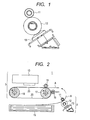
- FIG. 1 is a schematic diagram of an application portion which applies a pretreatment liquid to a recording medium related to one embodiment of the invention.
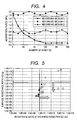
- FIG. 2 is a schematic diagram of an ink jet recording apparatus related to one embodiment of the invention.
- FIGS. 3A, 3B and 3C are model diagrams of the relationship between the permeation conditions of a pretreatment liquid and electrical resistance with respect to a recording medium.
- FIG. 4 is a graph illustrating the relationship between the number of sheets and adsorption force of a recording medium related to one embodiment of the invention.
- FIG. 5 is a graph illustrating the quality of adsorption force caused by the resistance ratio in the thickness direction and surface resistance ratio of a recording medium.
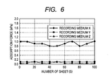
- FIG. 6 is a graph illustrating the relationship between the number of sheets and adsorption force of a recording medium related to a comparative example.
- FIG. 1 is a schematic diagram of an application portion which performs the application processing of applying a transparent pretreatment liquid to a recording medium before the recording of an ink jet recording apparatus related to one embodiment of the invention.
- a pretreatment liquid is held in a cap 13.
- an application roller 12 which comes into contact with the cap 13 rotates so as to follow the auxiliary roller 11.
- the pretreatment liquid supplied from the cap 13 adheres to the surface of the application roller 12 in a thinly drawn-out form. Therefore, when a recording medium is nipped and passes between the auxiliary roller 11 and the application roller 12, a transparent pretreatment liquid adheres to the surface of the recording medium which comes into contact with the application roller 12.
- This transparent pretreatment liquid is a liquid applied mainly in cases where a plain paper is used as a recording medium, and is a liquid used for the purpose of improvements in the deterioration (feathering) of the quality of the edges of a character or an image or in the oozing phenomenon (bleeding) of ink at boundary portions between a plurality of kinds of color ink.
- This pretreatment liquid generally includes a cohesion/fixation promoter which reacts, other than with water, with the ink discharged from a recording head, and promotes the cohesion or fixation of a color material, and is able to shorten the time taken until an ink drop is fixed on the surface of a recording medium after the ink drop has landed the recording medium.
- cohesion/fixation promoter univalent or bivalent metal salt or the like is typical. Additionally, in many cases, a nonvolatile solvent, a surfactant, a preservative, and the like other than the cohesion/fixation promoter are included in the pretreatment liquid. As just described, the quality of a character or image formed on a recording medium becomes high due to the application of the transparent pretreatment liquid.
- FIG. 2 is a schematic diagram of the configuration of the ink jet recording apparatus 1 related to the present embodiment. Portions other than the portions involved in the features of the present embodiment are omitted in FIG. 2 .
- the ink jet recording apparatus 1 has a sheet feed portion 2 which supplies a recording medium A, and a recording portion 3 which conveys the recording medium A supplied from the sheet feed portion 2 using an electrostatic belt 20 and performs recording on the recording medium A.
- a first face which is one face of the recording medium A or electrostatic belt 20 is referred to the surface, and a second face which is the other face opposite to the first face of the recording medium A or electrostatic belt 20 is referred to as the back.
- the recording medium is made to pass between the auxiliary roller 11 and the application roller 12.
- the recording medium A to the surface of which the pretreatment liquid has been applied passes through a recording medium conveyance system (not illustrated), and is conveyed to the electrostatic belt 20 which is a conveying belt for conveying the recording medium A of the recording portion 3. Then, the recording medium A is stacked on the electrostatic belt 20 so that the back of the recording medium A to which the pretreatment liquid is not applied comes into contact with the surface of the electrostatic belt 20. At this time, the surface of the recording medium A faces upwards where the recording head 10 is present.
- the electrostatic belt 20 is endless, and is formed to have an overall loop-shape.
- the electrostatic belt 20 may be integrally molded in the shape of a loop, or may be formed in the shape of a loop after being molded in the shape of a belt by connecting both ends thereof.
- the electrostatic belt 20 is held by a driving roller 17 and a driven roller 18 and is repeatedly rotated by the driving force of the driving roller 17.
- the electrostatic belt 20 has a two-layer structure of a surface layer and a back layer.
- the surface layer of the electrostatic belt 20 which adsorbs the back of the recording medium A is a resistance layer of which the volume resistance ratio is equal to or greater than 1.0.10 12 ( ⁇ .cm) .
- the back layer of the electrostatic belt 20 which comes into contact with the driving roller 17 and the driven roller 18 is an middle-resistance layer of which the volume resistance ratio is equal to or greater than 1.0x10 4 ( ⁇ .cm) and equal to or less than 1.0x10 9 ( ⁇ .cm) .
- PI Polyimide
- fluorine-based resin and the like are used as a base material which forms the electrostatic belt 20.
- an additive in which adjustment of ingredients or quantity has been made is added to the above-described base material. Carbon, a surfactant, and the like are used for the additive.
- the driving roller 17 is a first grounding portion which is grounded, and comes into contact with the back layer (middle-resistance layer) of the electrostatic belt 20, thereby grounding the back layer of the electrostatic belt 20.
- a power feed roller 16 which is a charge imparting portion imparts charges to the surface of the electrostatic belt 20.
- the back of the recording medium A comes into contact with the surface of the electrostatic belt 20 to which the charges have been imparted, the back of the recording medium A is electrostatically adsorbed on the surface of the electrostatic belt 20. This makes the recording medium A not easily separate from the electrostatic belt 2.
- the recording medium A is nipped and passes between a pinch roller 19 which is a second grounding portion which is grounded, and the electrostatic belt 20.
- the pinch roller 19 plays a mechanical role of pushing the recording medium A against the electrostatic belt 20, and an plays an electrical role of imparting second charges, with a sign which is reverse to that of first charges imparted to the surface layer of the electrostatic belt 20 by the power feed roller 16, to the surface of the recording medium A. That is, if the first charges are positive charges, the second charges are negative charges, and if the first charges are negative charges, the second charges are positive charges.
- the electrostatic adsorption force of the surface of the electrostatic belt 20 onto the back of the recording medium A becomes powerful. This makes the recording medium A less easily separated from the electrostatic belt 2.
- ink is discharged from the recording head 10 to the surface of the recording medium A to which the pretreatment liquid has been applied.
- the recording medium A is ejected by a sheet ejection tray (not illustrated) of the ink jet recording apparatus 1 after the recording by the recording head 10 is completed.
- the recording medium X was a plain paper to which a pretreatment liquid was not applied.
- the recording medium Y was one obtained by applying a pretreatment liquid, to which 0.3 wt% of surfactant has was added, to the surface of a plain paper.
- the recording medium Z was one obtained by applying a pretreatment liquid, in which the additive amount of the surfactant of the pretreatment liquid applied to the recording medium Y was increased to 5.0 wt%., to the surface of a plain paper.
- the application amount and application conditions of the pretreatment liquids to the surface of the recording medium Y and the recording medium Z were the same.
- the recording media X to Z measurement of a resistance ratio Rt in the thickness direction and a surface resistance ratio Rs was performed.
- the resistance ratio Rt in the thickness direction of a recording medium is a value obtained by dividing the resistance per unit area in the thickness direction of the recording medium by the thickness of the recording medium. That is, the resistance ratio Rt represents the average value of the total resistance ratio in the thickness direction of a recording medium.
- the unit of the surface resistance ratio Rs is typically denoted by ( ⁇ ).
- the surface resistance ratio units shall be expressed by ( ⁇ / ⁇ ) as meaning of resistance per square unit.
- the unit of the surface resistance ratio may be expressed by ( ⁇ /Sq.) or the like.
- FIGS. 3A to 3C Model diagrams of the relationship between the permeation conditions of a pretreatment liquid and Rt and Rs in the recording media X to Z are illustrated in FIGS. 3A to 3C.
- FIGS. 3A to 3C correspond to the recording media X to Z, respectively.
- FIGS. 3A to 3C show sections in the thickness direction of respective recording media, with the surface of each recording medium turned upward and the back thereof turned downward.
- a pretreatment liquid permeation layer B was not formed.
- a pretreatment liquid permeation layer B was formed on the recording medium Y and recording medium Z to which a pretreatment layer was applied. Additionally, in the recording medium Z of which the concentration of a surfactant of a pretreatment liquid was high, the pretreatment liquid permeation layer B was formed in the whole thickness direction. In contrast, in the recording medium Y of which the concentration of a surfactant of a pretreatment liquid was low, the pretreatment liquid permeation layer B was formed only partway through in the thickness direction.
- the pretreatment liquids have the action of lowering the electrical resistance of the recording media, and Rt and Rs of the recording media greatly change depending on the formation of the pretreatment liquid permeation layer. That is, it is considered that both Rt and Rs are high in the recording medium X in which the pretreatment liquid permeation layer B is not formed, and both Rt and Rs are low in the recording medium C in which the pretreatment liquid permeation layer B is formed in the whole thickness direction. Additionally, it is considered that, in the recording medium Y in which the pretreatment liquid permeation layer B is formed only on the surface side, the surface resistance ratio Rs is low, but the resistance ratio Rt in the thickness direction is high.
- the adsorption force to the electrostatic belt 20 was measured using the recording portion 3 illustrated in FIG. 2 .
- DC-2.0 kV of negative charges were imparted to each recording medium as the power feed conditions of the power feed roller 16. That is, negative charges were imparted to the surface of the electrostatic belt 20 by the power feed roller 16, and positive charges were applied to the surface of the recording medium by the pinch roller 19.
- the measurement was performed on 100 continuous sheets for each recording medium.
- FIG. 4 illustrates a graph illustrating the results.
- FIG. 4 illustrates changes in the adsorption force of every tenth recording media.
- the data of the recording medium X is indicated by a ⁇ mark
- the data of the recording medium Y is indicated by a ⁇ mark
- the data of the recording medium Z is indicated by a A mark.
- the vertical axis of FIG. 4 represents adsorption force (kPa) converted from horizontal tensile force required for separating a recording medium from the electrostatic belt 20, and the horizontal axis thereof represents the number of sheets which were continuously passed.
- the adsorption force was high up to several sheets, but the adsorption force reduced gradually as sheets continued passing, and the adsorption force was hardly generated in the 60th to 100th sheets.
- the recording medium Y it was found that a high adsorption force around 1.9 kPa was maintained from the first sheet to the 100th sheet within the range of a certain degree of variation.
- a slightly low adsorption force of about 0.8 kPa was maintained from the first sheet to the 100th sheet.
- the adsorption force to the electrostatic belt 20 was measured after recording media with various resistance ratios in the thickness directions and various surface resistance ratios was prepared.
- the adjustment of the resistance ratio in the thickness direction and surface resistance ratio of the recording media was performed by changing the concentration of surfactant in a pretreatment liquid applied to each recording medium.
- all of the recording media before application of a pretreatment liquid were the same plain papers, and the application amount and application conditions of the pretreatment liquid to each recording medium were fixed. The results are illustrated in FIG. 5 . In FIG.
- the vertical axis represents the surface resistance ratio of the recording media
- the horizontal axis is the resistance ratio in the thickness direction of the recording media. Additionally, the errors of the electrical resistance of the recording media caused by the influence of humidity are also included in the results illustrated in FIG. 5 .
- Marks O, A, and X in the graph of FIG. 5 indicate the level of the adsorption force of the recording media to the electrostatic belt 20, respectively.
- Mark O indicates that the adsorption force is equal to or greater than 1.0 kPa
- Mark ⁇ indicates that the adsorption force is equal to or greater than 0.5 kPa and less than 1.0 kPa
- Mark X indicates that the adsorption force is less than 0.5 kPa.
- the factor which has the most influence on the adsorption force of the recording media to the electrostatic belt 20 is the surface resistance ratio of the recording media. It was found that, if the surface resistance ratio is equal to or less than about 5.0x10 12 ( ⁇ / ⁇ ), a high adsorption force is obtained. Additionally, the resistance ratio in the thickness direction has also an influence on the adsorption force of the recording medium to the electrostatic belt 20. It was found that, if the resistance ratio in the thickness direction is equal to or greater than 5.0x10 9 ( ⁇ .cm), a high adsorption force is obtained.
- the pretreatment liquid may be adjusted so that the surface resistance ratio of a recording medium becomes equal to or less than 5.0x10 12 ( ⁇ / ⁇ ) and the resistance ratio in the thickness direction of the recording medium becomes equal to or greater than 5.0x10 9 ( ⁇ .cm) .
- the electrostatic belt 20 of the recording portion 3 illustrated in FIG. 2 in the above-described recording media X to Z was changed to an electrostatic belt with a single layer structure of which the volume resistance ratio is 1.0x10 16 ( ⁇ .cm) and the adsorption force to this electrostatic belt was measured.
- DC-2.0 kV of negative charges were applied to each recording medium as the power feed conditions of the power feed roller 16, and the measurement was performed for 100 continuous sheets for each recording medium.
- the data of the recording medium X is indicated by a ⁇ mark
- the data of the recording medium Y is indicated by a ⁇ mark
- the data of the recording medium Z is indicated by a A mark.
- the vertical axis of FIG. 6 represents adsorption force (kPa) converted from horizontal tensile force required for separating a recording medium from the electrostatic belt, and the horizontal axis thereof represents the number of sheets which were continuously passed.
- a transparent pretreatment liquid applied to a recording medium For example, water, cohesion/fixation promoter, a nonvolatile solvent, a surfactant, a preservative, and the like are included in a transparent pretreatment liquid applied to a recording medium. Even when the formulation of these ingredients of the pretreatment liquid is adjusted, any decrease in the resistance ratio in the thickness direction or surface resistance ratio of a recording medium to which a pretreatment liquid has been applied cannot be avoided. Therefore, it is extremely difficult to realize the combination of a system which applies a pretreatment liquid to a recording medium and an electrostatic belt conveyance system using electrostatic adsorption of a recording medium in an electrostatic belt of a single layer structure.
- a sufficient adsorption force of the electrostatic belt 20 with respect to the recording medium A was secured by the adoption of the DC charging method and by the adjustment of the surface resistance ratio and resistance ratio in the thickness direction of the recording medium A. Specifically, it is desirable that adjustment is made so that the surface resistance ratio of the recording medium A becomes equal to or less than 5.0x10 12 ( ⁇ / ⁇ ) and the resistance ratio in the thickness direction of the recording medium A becomes equal to or greater than 5.0x10 9 ( ⁇ .cm).
- the concentration of a surfactant in a pretreatment liquid applied to a recording medium was changed for the adjustment of the surface resistance ratio and resistance ratio in the thickness direction of the recording medium.
- other methods may be used for the adjustment of the surface resistance ratio and resistance ratio in the thickness direction of the recording medium.
- the sheet feed portion 2 may not have the application portion.
- the application portion may be provided in the recording head 10.
- the recording head 10 discharges a pretreatment liquid to the recording medium A before ink is discharged. Thereafter, ink is discharged to the recording medium A to which the pretreatment liquid has been applied.
- the application portion illustrated in FIG. 1 may be provided independently from the ink jet recording apparatus 1. That is, a configuration may be adopted in which the recording medium A to which a pretreatment liquid has been applied by this independently provided application portion is stacked on the recording medium cassette 15. In this case, the recording medium A which is stacked on the recording medium cassette 15 and has the pretreatment liquid applied thereto is conveyed directly to the electrostatic belt 20, and recording is performed on the recording medium by the recording head 10.
Landscapes
- Ink Jet (AREA)
- Feeding Of Articles By Means Other Than Belts Or Rollers (AREA)
- Handling Of Sheets (AREA)
Abstract
Description
- The present invention relates to an ink jet recording apparatus which performs recording on a recording medium.
- Recently, in order to meet market demands for higher image quality and higher speed of recording in an ink jet recording apparatus, the realization of multiple colors, higher density, smaller drops, a larger number of nozzles, and the like are progressing. As a result, the ink jet recording apparatus is able to provide a user with a photo image which is no way inferior to a silver halide photograph when printing to special media as well as for the purposes of printing of web content or a text on a plain paper. Additionally, an ink jet recording apparatus for business or industry with increased printing speeds like those of a laser beam printer has also been developed.
- In the ink jet recording apparatus for business or industry, the nozzles of the recording head are often made long in order to increase the printing speed. However, in such an ink jet recording apparatus, it is difficult to keep constant the distance (hereinafter referred to as the "distance with respect to sheet") from the nozzle face of a recording head to the recording face of the recording medium. This is because the distance from a pinch roller which supports the recording medium on the upstream side from the recording head to a sheet ejection roller which supports the recording medium on the downstream side from the recording head becomes longer. In such an ink jet recording apparatus, floating of a recording medium, a flapping (cockling) phenomenon which is caused as ink permeates into a recording medium, or the like easily occurs, it is difficult to keep the distance with respect to sheet constant between the pinch roller and the sheet ejection roller.
- In the ink jet recording apparatus, in order to keep the distance with respect to sheet constant, an electrostatic adsorption conveyance system, a perforated platen conveyance system, or the like is used. The electrostatic adsorption conveyance system adopts an endless conveying belt in a recording medium conveying mechanism, and makes static electricity generated on the surface of the conveying belt adsorb and convey the recording medium. The perforated platen conveyance system makes the back of a recording medium be air-adsorbed on the conveying belt immediately below a recording area.
- In Japanese Patent Application Laid-Open No.
2001-353861 - Also in Japanese Patent No.
3804928 2004-262557 - In the electrostatic adsorption conveyance system, which performs DC charging on the conveying belt of a single layer structure, disclosed in Japanese Patent Application Laid-Open No.
2001-353861 - Additionally, it is known that, if the charging method is changed to the AC charging from the DC charging in the configuration of the electrostatic adsorption conveyance system disclosed in Japanese Patent Application Laid-Open No.
2001-353861 - In the electrostatic adsorption conveyance system, which performs the AC charging on the conveying belt of a two-layer structure, disclosed in Japanese Patent No.
3804928 2004-262557 - Although the average charging distribution of the conveying belt immediately below the recording head is uniform since the surface potential becomes "0", a positively charged portion and a negatively charged portion are microscopically generated in the conveying direction of a recording media on the conveying belt. On the boundary portion between the positively charged portion and the negatively charged portion, an ink drop discharged onto a recording medium is pulled toward the positively charged portion or the negatively charged portion by Coulomb forces. Therefore, since the ink drop does not land exactly on the recording medium at the boundary portion between the positively charged portion and the negatively charged portion on the conveying belt, it is believed that this appears as a recording streak. This phenomenon is particularly conspicuous in a case where the velocity of an ink drop is slow.
- Moreover, in a case where the AC charges are imparted to the conveying belt, it is known that there is also a problem in that the adsorption force of the conveying belt to the recording medium decreases abruptly when ink mist or dust adheres to the conveying belt. In a case where positively charged portions and negatively charged portions are repeatedly formed in the conveying direction on the conveying belt which has been subjected to the AC charging, and the surface resistance of the conveying belt is high, movement of charges does not occur between the positively charged portion and the negatively charged portion. However, since the surface resistance of the conveying belt decreases in a case where ink mist, dust, or the like adheres to the conveying belt, movement of charges occurs between the positively charged portion and the negatively charged portion of the conveying belt. Thereby, since the surface charges of the conveying belt will be cancelled, it is believed that the adsorption force of the conveying belt to the recording medium will decrease.
- The invention has been made in consideration of the above problems, and the object of the invention is to provide an ink jet recording apparatus capable of landing an ink drop on an exact position on a recording medium.
- In order to achieve the above object, the ink jet recording apparatus of the invention is an ink jet recording apparatus which records on a recording medium which has been subjected to application processing with a pretreatment liquid. The apparatus includes: a conveying belt having a resistance layer formed on a first face thereof; a charge imparting portion which imparts first charges to the first face of the conveying belt; and a recording head which discharges ink to the first face of the recording medium when a second face opposite to the first face of the recording medium comes into contact with the first face of the conveying belt to which the first charges have been imparted.
- According to the invention, it is possible to provide an ink jet recording apparatus capable of bringing a recording medium into close contact with the conveying belt and making an ink drop land on an exact position on the recording medium.
- Further features of the present invention will become apparent from the following description of exemplary embodiments with reference to the attached drawings.
-
FIG. 1 is a schematic diagram of an application portion which applies a pretreatment liquid to a recording medium related to one embodiment of the invention. -
FIG. 2 is a schematic diagram of an ink jet recording apparatus related to one embodiment of the invention. -
FIGS. 3A, 3B and 3C are model diagrams of the relationship between the permeation conditions of a pretreatment liquid and electrical resistance with respect to a recording medium. -
FIG. 4 is a graph illustrating the relationship between the number of sheets and adsorption force of a recording medium related to one embodiment of the invention. -
FIG. 5 is a graph illustrating the quality of adsorption force caused by the resistance ratio in the thickness direction and surface resistance ratio of a recording medium. -
FIG. 6 is a graph illustrating the relationship between the number of sheets and adsorption force of a recording medium related to a comparative example. - A preferred embodiment of the present invention will now be described in detail in accordance with the accompanying drawings.
-
FIG. 1 is a schematic diagram of an application portion which performs the application processing of applying a transparent pretreatment liquid to a recording medium before the recording of an ink jet recording apparatus related to one embodiment of the invention. - A pretreatment liquid is held in a
cap 13. When anauxiliary roller 11 rotates, anapplication roller 12 which comes into contact with thecap 13 rotates so as to follow theauxiliary roller 11. As a result, the pretreatment liquid supplied from thecap 13 adheres to the surface of theapplication roller 12 in a thinly drawn-out form. Therefore, when a recording medium is nipped and passes between theauxiliary roller 11 and theapplication roller 12, a transparent pretreatment liquid adheres to the surface of the recording medium which comes into contact with theapplication roller 12. - This transparent pretreatment liquid is a liquid applied mainly in cases where a plain paper is used as a recording medium, and is a liquid used for the purpose of improvements in the deterioration (feathering) of the quality of the edges of a character or an image or in the oozing phenomenon (bleeding) of ink at boundary portions between a plurality of kinds of color ink. This pretreatment liquid generally includes a cohesion/fixation promoter which reacts, other than with water, with the ink discharged from a recording head, and promotes the cohesion or fixation of a color material, and is able to shorten the time taken until an ink drop is fixed on the surface of a recording medium after the ink drop has landed the recording medium. As the cohesion/fixation promoter, univalent or bivalent metal salt or the like is typical. Additionally, in many cases, a nonvolatile solvent, a surfactant, a preservative, and the like other than the cohesion/fixation promoter are included in the pretreatment liquid. As just described, the quality of a character or image formed on a recording medium becomes high due to the application of the transparent pretreatment liquid.
-
FIG. 2 is a schematic diagram of the configuration of the ink jet recording apparatus 1 related to the present embodiment. Portions other than the portions involved in the features of the present embodiment are omitted inFIG. 2 . The ink jet recording apparatus 1 has asheet feed portion 2 which supplies a recording medium A, and arecording portion 3 which conveys the recording medium A supplied from thesheet feed portion 2 using anelectrostatic belt 20 and performs recording on the recording medium A. In addition, in the present embodiment, a first face which is one face of the recording medium A orelectrostatic belt 20 is referred to the surface, and a second face which is the other face opposite to the first face of the recording medium A orelectrostatic belt 20 is referred to as the back. - In the
sheet feed portion 2, in order to separate the recording medium A stacked on arecording medium cassette 15 one by one with a pickup mechanism (not illustrated) and to apply a transparent pretreatment liquid to the surface of the recording medium, the recording medium is made to pass between theauxiliary roller 11 and theapplication roller 12. - Thereafter, the recording medium A to the surface of which the pretreatment liquid has been applied passes through a recording medium conveyance system (not illustrated), and is conveyed to the
electrostatic belt 20 which is a conveying belt for conveying the recording medium A of therecording portion 3. Then, the recording medium A is stacked on theelectrostatic belt 20 so that the back of the recording medium A to which the pretreatment liquid is not applied comes into contact with the surface of theelectrostatic belt 20. At this time, the surface of the recording medium A faces upwards where therecording head 10 is present. - The
electrostatic belt 20 is endless, and is formed to have an overall loop-shape. Theelectrostatic belt 20 may be integrally molded in the shape of a loop, or may be formed in the shape of a loop after being molded in the shape of a belt by connecting both ends thereof. Theelectrostatic belt 20 is held by a drivingroller 17 and a drivenroller 18 and is repeatedly rotated by the driving force of the drivingroller 17. - The
electrostatic belt 20 has a two-layer structure of a surface layer and a back layer. The surface layer of theelectrostatic belt 20 which adsorbs the back of the recording medium A is a resistance layer of which the volume resistance ratio is equal to or greater than 1.0.1012 (Ω.cm) . Additionally, the back layer of theelectrostatic belt 20 which comes into contact with the drivingroller 17 and the drivenroller 18 is an middle-resistance layer of which the volume resistance ratio is equal to or greater than 1.0x10⁴ (Ω.cm) and equal to or less than 1.0x10⁹ (Ω.cm) . As a base material which forms theelectrostatic belt 20, for example, PI (Polyimide), fluorine-based resin, and the like are used. For the adjustment of the volume resistance ratio of theelectrostatic belt 20, an additive in which adjustment of ingredients or quantity has been made is added to the above-described base material. Carbon, a surfactant, and the like are used for the additive. - The driving
roller 17 is a first grounding portion which is grounded, and comes into contact with the back layer (middle-resistance layer) of theelectrostatic belt 20, thereby grounding the back layer of theelectrostatic belt 20. In this state, apower feed roller 16 which is a charge imparting portion imparts charges to the surface of theelectrostatic belt 20. Thereafter, when the back of the recording medium A comes into contact with the surface of theelectrostatic belt 20 to which the charges have been imparted, the back of the recording medium A is electrostatically adsorbed on the surface of theelectrostatic belt 20. This makes the recording medium A not easily separate from theelectrostatic belt 2. - Thereafter, the recording medium A is nipped and passes between a
pinch roller 19 which is a second grounding portion which is grounded, and theelectrostatic belt 20. Thepinch roller 19 plays a mechanical role of pushing the recording medium A against theelectrostatic belt 20, and an plays an electrical role of imparting second charges, with a sign which is reverse to that of first charges imparted to the surface layer of theelectrostatic belt 20 by thepower feed roller 16, to the surface of the recording medium A. That is, if the first charges are positive charges, the second charges are negative charges, and if the first charges are negative charges, the second charges are positive charges. By imparting charges with signs which are reverse to each other to the surface of theelectrostatic belt 20, and the surface of the recording medium A, the electrostatic adsorption force of the surface of theelectrostatic belt 20 onto the back of the recording medium A becomes powerful. This makes the recording medium A less easily separated from theelectrostatic belt 2. - After the recording medium A has come into contact with the
pinch roller 19, ink is discharged from therecording head 10 to the surface of the recording medium A to which the pretreatment liquid has been applied. The recording medium A is ejected by a sheet ejection tray (not illustrated) of the ink jet recording apparatus 1 after the recording by therecording head 10 is completed. - (Regarding Resistance Ratio in Thickness Direction and Surface Resistance Ratio of Recording Medium)
- Application processing with a pretreatment liquid to the surfaces of recording media was performed under different conditions, always using the same plain papers as the recording media. Thereby the following three kinds of recording media A to Z were prepared. The recording medium X was a plain paper to which a pretreatment liquid was not applied. The recording medium Y was one obtained by applying a pretreatment liquid, to which 0.3 wt% of surfactant has was added, to the surface of a plain paper. The recording medium Z was one obtained by applying a pretreatment liquid, in which the additive amount of the surfactant of the pretreatment liquid applied to the recording medium Y was increased to 5.0 wt%., to the surface of a plain paper. In addition, the application amount and application conditions of the pretreatment liquids to the surface of the recording medium Y and the recording medium Z were the same. As for the recording media X to Z, measurement of a resistance ratio Rt in the thickness direction and a surface resistance ratio Rs was performed.
- In addition, the resistance ratio Rt in the thickness direction of a recording medium is a value obtained by dividing the resistance per unit area in the thickness direction of the recording medium by the thickness of the recording medium. That is, the resistance ratio Rt represents the average value of the total resistance ratio in the thickness direction of a recording medium.
- Additionally, the unit of the surface resistance ratio Rs is typically denoted by (Ω). However, in order to be distinguished from the resistance R between two points which are merely different from each other, the surface resistance ratio units shall be expressed by (Ω/□) as meaning of resistance per square unit. Additionally, the unit of the surface resistance ratio may be expressed by (Ω/Sq.) or the like.
- Measurement results of Rt and Rs of recording media X to Z are shown below.
- Recording medium X


- Recording medium Y


- Recording medium Z


- Model diagrams of the relationship between the permeation conditions of a pretreatment liquid and Rt and Rs in the recording media X to Z are illustrated in
FIGS. 3A to 3C. FIGS. 3A to 3C correspond to the recording media X to Z, respectively.FIGS. 3A to 3C show sections in the thickness direction of respective recording media, with the surface of each recording medium turned upward and the back thereof turned downward. - In the recording medium X to which a pretreatment liquid was not applied, as illustrated in
FIG. 3A , a pretreatment liquid permeation layer B was not formed. On the other hand, as illustrated inFIGS. 3B and 3C , a pretreatment liquid permeation layer B was formed on the recording medium Y and recording medium Z to which a pretreatment layer was applied. Additionally, in the recording medium Z of which the concentration of a surfactant of a pretreatment liquid was high, the pretreatment liquid permeation layer B was formed in the whole thickness direction. In contrast, in the recording medium Y of which the concentration of a surfactant of a pretreatment liquid was low, the pretreatment liquid permeation layer B was formed only partway through in the thickness direction. - From the above results, it is considered that the pretreatment liquids have the action of lowering the electrical resistance of the recording media, and Rt and Rs of the recording media greatly change depending on the formation of the pretreatment liquid permeation layer. That is, it is considered that both Rt and Rs are high in the recording medium X in which the pretreatment liquid permeation layer B is not formed, and both Rt and Rs are low in the recording medium C in which the pretreatment liquid permeation layer B is formed in the whole thickness direction. Additionally, it is considered that, in the recording medium Y in which the pretreatment liquid permeation layer B is formed only on the surface side, the surface resistance ratio Rs is low, but the resistance ratio Rt in the thickness direction is high.
- With respect to these three kinds of recording media X to Z, the adsorption force to the
electrostatic belt 20 was measured using therecording portion 3 illustrated inFIG. 2 . In this measurement, DC-2.0 kV of negative charges were imparted to each recording medium as the power feed conditions of thepower feed roller 16. That is, negative charges were imparted to the surface of theelectrostatic belt 20 by thepower feed roller 16, and positive charges were applied to the surface of the recording medium by thepinch roller 19. The measurement was performed on 100 continuous sheets for each recording medium. -
FIG. 4 illustrates a graph illustrating the results.FIG. 4 illustrates changes in the adsorption force of every tenth recording media. The data of the recording medium X is indicated by a ◆ mark, the data of the recording medium Y is indicated by a ■ mark, and the data of the recording medium Z is indicated by a A mark. The vertical axis ofFIG. 4 represents adsorption force (kPa) converted from horizontal tensile force required for separating a recording medium from theelectrostatic belt 20, and the horizontal axis thereof represents the number of sheets which were continuously passed. - In the recording medium X, it was found that the adsorption force was high up to several sheets, but the adsorption force reduced gradually as sheets continued passing, and the adsorption force was hardly generated in the 60th to 100th sheets. In the recording medium Y, it was found that a high adsorption force around 1.9 kPa was maintained from the first sheet to the 100th sheet within the range of a certain degree of variation. In the recording medium Z, it was found that a slightly low adsorption force of about 0.8 kPa was maintained from the first sheet to the 100th sheet.
- From these experiment results, it was found that the resistance ratio in the thickness direction and surface resistance ratio of a recording medium have a great influence on the adsorption force to the
electrostatic belt 20 in the conveyance system using theelectrostatic belt 20 shown inFIG. 2 . - Moreover, in order to investigate the influence of the resistance ratio in the thickness direction and surface resistance ratio of recording media, on the adsorption force to the
electrostatic belt 20, the adsorption force to theelectrostatic belt 20 was measured after recording media with various resistance ratios in the thickness directions and various surface resistance ratios was prepared. The adjustment of the resistance ratio in the thickness direction and surface resistance ratio of the recording media was performed by changing the concentration of surfactant in a pretreatment liquid applied to each recording medium. In addition, all of the recording media before application of a pretreatment liquid were the same plain papers, and the application amount and application conditions of the pretreatment liquid to each recording medium were fixed. The results are illustrated inFIG. 5 . InFIG. 5 , the vertical axis represents the surface resistance ratio of the recording media, and the horizontal axis is the resistance ratio in the thickness direction of the recording media. Additionally, the errors of the electrical resistance of the recording media caused by the influence of humidity are also included in the results illustrated inFIG. 5 . - Marks O, A, and X in the graph of
FIG. 5 indicate the level of the adsorption force of the recording media to theelectrostatic belt 20, respectively. Mark O indicates that the adsorption force is equal to or greater than 1.0 kPa, Mark ▲ indicates that the adsorption force is equal to or greater than 0.5 kPa and less than 1.0 kPa, and Mark X indicates that the adsorption force is less than 0.5 kPa. - It is understood from
FIG. 5 that the factor which has the most influence on the adsorption force of the recording media to theelectrostatic belt 20 is the surface resistance ratio of the recording media. It was found that, if the surface resistance ratio is equal to or less than about 5.0x10¹² (Ω/□), a high adsorption force is obtained. Additionally, the resistance ratio in the thickness direction has also an influence on the adsorption force of the recording medium to theelectrostatic belt 20. It was found that, if the resistance ratio in the thickness direction is equal to or greater than 5.0x10⁹ (Ω.cm), a high adsorption force is obtained. - That is, it was found that it is possible to perform stable conveyance of the recording media by adjusting the pretreatment liquid in a case where the pretreatment liquid is applied to the recording media in a conveyance system which has adopted a DC charging method using an
electrostatic belt 20 with a two-layer structure illustrated inFIG. 2 . Specifically, it was found that the pretreatment liquid may be adjusted so that the surface resistance ratio of a recording medium becomes equal to or less than 5.0x10¹² (Ω/□) and the resistance ratio in the thickness direction of the recording medium becomes equal to or greater than 5.0x10⁹ (Ω.cm) . - Next, as comparative examples, only the
electrostatic belt 20 of therecording portion 3 illustrated inFIG. 2 in the above-described recording media X to Z was changed to an electrostatic belt with a single layer structure of which the volume resistance ratio is 1.0x10¹⁶ (Ω.cm) and the adsorption force to this electrostatic belt was measured. In this measurement, DC-2.0 kV of negative charges were applied to each recording medium as the power feed conditions of thepower feed roller 16, and the measurement was performed for 100 continuous sheets for each recording medium. The data of the recording medium X is indicated by a ◆ mark, the data of the recording medium Y is indicated by a ■ mark, and the data of the recording medium Z is indicated by a A mark. The vertical axis ofFIG. 6 represents adsorption force (kPa) converted from horizontal tensile force required for separating a recording medium from the electrostatic belt, and the horizontal axis thereof represents the number of sheets which were continuously passed. - In the recording medium X to which a pretreatment liquid is not applied, it was found that an adsorption force of about 1.0 kPa was maintained from the first sheet to the 100th sheet. In any of the recording medium Y and recording medium Z to which a pretreatment liquid is applied, it was found that the adsorption force was extremely low from the first sheet to the 100th sheet.
- From these experiment results, it was found that a sufficient adsorption force of the electrostatic belt to a recording medium was not obtained depending on the application of a pretreatment liquid to the recording medium in the electrostatic belt conveyance system which has adopted a DC charging method using an electrostatic belt with a single layer structure. Additionally, even in an electrostatic belt conveyance system in which only the charging method is changed to an AC charging method using the same electrostatic belt with a single layer structure, the results were almost the same as the results illustrated in
FIG. 6 . From these results, it is considered that a sufficient adsorption force of the electrostatic belt with respect to a recording medium was not obtained in a case where the resistance ratio in the thickness direction and the surface resistance ratio of the recording medium are low when the electrostatic belt with a single layer structure was used. - For example, water, cohesion/fixation promoter, a nonvolatile solvent, a surfactant, a preservative, and the like are included in a transparent pretreatment liquid applied to a recording medium. Even when the formulation of these ingredients of the pretreatment liquid is adjusted, any decrease in the resistance ratio in the thickness direction or surface resistance ratio of a recording medium to which a pretreatment liquid has been applied cannot be avoided. Therefore, it is extremely difficult to realize the combination of a system which applies a pretreatment liquid to a recording medium and an electrostatic belt conveyance system using electrostatic adsorption of a recording medium in an electrostatic belt of a single layer structure.
- Next, recording was performed using the
recording portion 3 illustrated inFIG. 2 on the recording medium Y to which the pretreatment liquid, in which the additive amount of the surfactant illustrating good results inFIG. 4 is 0.3 3 wt%, has been applied, and a recording streak generated in the recording medium was evaluated. As the conditions of power feed to theelectrostatic belt 20 by thepower feed roller 16, two conditions of DC-2.0 kV charging and AC±2.0 kV charging were adopted. Additionally, as the conditions of the distance from the discharge port face of therecording head 10 to the surface of theelectrostatic belt 20, two conditions of 1.0 mm and 2.0 mm were adopted. In the respective conditions, the recording streak of an image recorded on the surface of the recording medium was evaluated. - In the case of the AC charging condition, a recording streak was confirmed at the portion of the recording medium on the boundary between a positively charged portion of the
electrostatic roller 20 to which positive charges have been imparted and a negatively charged portion of the recording medium to which negative charges have been imparted. Additionally, the degree of the recording streak was worse in the case of the condition where the distance from the discharge port face of therecording head 10 to the surface of theelectrostatic belt 20 was 2.0 mm than in the case of the condition that the distance was 1.0 mm. It is considered that this is because, due to air resistance, the velocity of ink decreases until landing on the surface of the recording medium after discharge of an ink drop as the distance from the discharge port face of therecording head 10 to the surface of theelectrostatic belt 20 increases. If the velocity of the ink decreases, since the influence of the Coulomb forces which act on each other due to the charges of the surface of the recording medium and the charges that the ink drop carries increases, the landing position of the ink drop to the surface of the recording medium will deviate. - On the other hand, in the case of the DC charging condition, a recording streak was scarcely observed on the recording medium. In the case of the condition where the distance from the discharge port face of the
recording head 10 to the surface of theelectrostatic belt 20 was 1.0 mm, the level of image quality was high, and even in the case of the condition that the distance was 2.0 mm, the resulting image quality level was allowable. As just described, it was found that the image quality of a recording medium became better under DC charging condition where one of positive charges and negative charges were imparted to theelectrostatic belt 20 than under the AC charging condition where the positively charged portion to which positive charges have been imparted and the negatively charged portion to which negative charges have been imparted were generated in theelectrostatic belt 20. - As described above, in the electrostatic belt conveyance system using the
electrostatic belt 20 with a two-layer structure illustrated inFIG. 2 , a sufficient adsorption force of theelectrostatic belt 20 with respect to the recording medium A was secured by the adoption of the DC charging method and by the adjustment of the surface resistance ratio and resistance ratio in the thickness direction of the recording medium A. Specifically, it is desirable that adjustment is made so that the surface resistance ratio of the recording medium A becomes equal to or less than 5.0x10¹² (Ω/□) and the resistance ratio in the thickness direction of the recording medium A becomes equal to or greater than 5.0x10⁹ (Ω.cm). - In addition, in the electrostatic belt conveyance system which has adopted the DC charging method using the
electrostatic belt 20 with a two-layer structure illustrated inFIG. 2 , even in case where a pretreatment liquid was applied to the back of the recording medium A instead of the surface of the recording medium A, the same results as those ofFIGS. 4 and 5 were obtained. That is, it was found that, even when a pretreatment liquid is applied to the back of the recording medium A and the back of the recording medium A is adsorbed by theelectrostatic belt 20, a sufficient adsorption force of theelectrostatic belt 20 with respect to the recording medium A is secured. Even in this case, it is desirable that adjustment is made so that the resistance ratio of the back of the recording medium A becomes equal to or less than 5.0x10¹² (Ω/□) and the resistance ratio in the thickness direction of the recording medium A becomes equal to or greater than 5.0x10⁹ (Ω.cm) . - Additionally, in the electrostatic belt conveyance system which has adopted the DC charging method using the
electrostatic belt 20 with a two-layer structure illustrated inFIG. 2 , even in a case where a pretreatment liquid was applied to both the surface and back of the recording medium A, the same results as those ofFIGS. 4 and 5 were obtained. That is, it was found that, even when a pretreatment liquid is applied to the surface and back of the recording medium A and one of the surface and the back of the recording medium A is adsorbed by theelectrostatic belt 20, a sufficient adsorption force of theelectrostatic belt 20 with respect to the recording medium A is secured. In this case, it is desirable that adjustment is made so that the average value of the resistance ratio of the surface of the recording medium A and the resistance ratio of the back of the recording medium becomes equal to or less than 5.0x10¹³ (Ω/□) and the resistance ratio in the thickness direction of the recording medium A becomes equal to or greater than 1.0x10⁹ (Ω.cm). - Moreover, in a case where a pretreatment liquid was applied to both the surface and back of the recording medium A, it is possible to keep the quality of recording of both faces of the recording medium A high even in a case where double-sided printing is performed. That is, even in a case where recording is performed not only on the surface of the recording medium A but on the back of the recording medium A in the
recording portion 3 of the recording apparatus 1 illustrated inFIG. 2 , it is possible to prevent feathering or bleeding on both faces of the recording medium A. - Additionally, in the present embodiment, the concentration of a surfactant in a pretreatment liquid applied to a recording medium was changed for the adjustment of the surface resistance ratio and resistance ratio in the thickness direction of the recording medium. However, other methods may be used for the adjustment of the surface resistance ratio and resistance ratio in the thickness direction of the recording medium. For example, it is possible to adjust the surface resistance ratio and resistance ratio in the thickness direction of a recording medium by changing the viscosity of a pretreatment liquid applied to a recording medium or by changing the application amount of a pretreatment liquid to a recording medium.
- Additionally, the ink jet recording apparatus 1 illustrated in
FIG. 2 , thesheet feed portion 2 may not have the application portion. For example, in the ink jet recording apparatus 1, the application portion may be provided in therecording head 10. In this case, therecording head 10 discharges a pretreatment liquid to the recording medium A before ink is discharged. Thereafter, ink is discharged to the recording medium A to which the pretreatment liquid has been applied. - Additionally, although the ink jet recording apparatus 1 illustrated in
FIG. 2 includes the application portion as a part, the application portion illustrated inFIG. 1 may be provided independently from the ink jet recording apparatus 1. That is, a configuration may be adopted in which the recording medium A to which a pretreatment liquid has been applied by this independently provided application portion is stacked on therecording medium cassette 15. In this case, the recording medium A which is stacked on therecording medium cassette 15 and has the pretreatment liquid applied thereto is conveyed directly to theelectrostatic belt 20, and recording is performed on the recording medium by therecording head 10. - While the present invention has been described with reference to exemplary embodiments, it is to be understood that the invention is not limited to the disclosed exemplary embodiments. The scope of the following claims is to be accorded the broadest interpretation so as to encompass all such modifications and equivalent structures and functions.
Claims (15)
- An ink jet recording apparatus which records on a recording medium which has been subjected to application processing with a pretreatment liquid, the apparatus comprising:a conveying belt having a resistance layer formed on a first face thereof;a charge imparting portion which imparts first charges to the first face of the conveying belt; anda recording head which discharges ink to the first face of the recording medium when a second face opposite to the first face of the recording medium comes into contact with the first face of the conveying belt to which the first charges have been imparted.
- The ink jet recording apparatus according to Claim 1,
wherein the volume resistance ratio of the resistance layer is equal to or greater than 1.0x10¹² (Ω.cm) . - The ink jet recording apparatus according to Claim 1 or 2,
wherein the conveying belt consists of two layer of a resistance layer and a middle-resistance layer of which the volume resistance ratio is lower than the resistance layer. - The ink jet recording apparatus according to Claim 3,
wherein the volume resistance ratio of the middle-resistance layer is equal to greater than 1.0x10⁴ (Ω.cm) and equal to or less than 1.0x10⁹ (Ω.cm) . - The ink jet recording apparatus according to according to any one of Claims 1 to 4, further comprising a first grounding portion which grounds the second face of the conveying belt when the charge imparting portion imparts the first charges to the first face of the conveying belt.
- The ink jet recording apparatus according to any one of Claims 1 to 5,
wherein when the second face of the recording medium comes into contact with the first face of the conveying belt to which the first charges have been imparted, the recording head discharges the ink to the first face of the recording medium after the second charges with a sign reverse to that of the first charges are imparted to the first face of the recording medium. - The ink jet recording apparatus according to Claim 6, further comprising a second grounding portion which grounds the first face of the recording medium when the second charges are imparted.
- The ink jet recording apparatus according to any one of Claims 1 to 7,
wherein a pretreatment liquid is applied to one of the first face and the second face of the recording medium in the application processing. - The ink jet recording apparatus according to Claim 8,
wherein after the application processing, the recording medium has a resistance ratio equal to or less than 5.0x10¹² (Ω/□) on the face to which the pretreatment liquid has been applied . - The ink jet recording apparatus according to any one of Claims 1 to 7,
wherein a pretreatment liquid is applied to both of the first face and the second face of the recording medium in the application processing. - The ink jet recording apparatus according to Claim 10,
wherein the average value of the resistance ratio of the first face and the resistance ratio of the second face in the recording medium after the application processing is equal to or less than 1.0x10¹³ (Ω/□). - The ink jet recording apparatus according to Claim 10 or 11,
wherein when the second face of the recording medium comes into contact with the first face of the conveying belt to which the first charges have been imparted, the recording head discharges the ink to the first face of the recording medium, and when the first face of the recording medium comes into contact with the first face of the conveying belt to which the first charges have been imparted, the recording head discharges the ink to the second face of the recording medium. - The ink jet recording apparatus according to any one of Claims 8 to 12,
wherein the resistance ratio in the thickness direction of the recording medium after the application processing is equal to or greater than 5.0x10⁹ (Ω.cm). - The ink jet recording apparatus according to any one of Claims 1 to 13, further comprising an application portion which performs the application processing on the recording medium.
- The ink jet recording apparatus according to Claim 14,
wherein the application portion is provided in the recording head.
Applications Claiming Priority (1)
| Application Number | Priority Date | Filing Date | Title |
|---|---|---|---|
| JP2009285194A JP5627225B2 (en) | 2009-12-16 | 2009-12-16 | Inkjet recording device |
Publications (2)
| Publication Number | Publication Date |
|---|---|
| EP2335932A1 true EP2335932A1 (en) | 2011-06-22 |
| EP2335932B1 EP2335932B1 (en) | 2013-07-17 |
Family
ID=43618703
Family Applications (1)
| Application Number | Title | Priority Date | Filing Date |
|---|---|---|---|
| EP20100015479 Not-in-force EP2335932B1 (en) | 2009-12-16 | 2010-12-09 | Ink jet recording apparatus |
Country Status (3)
| Country | Link |
|---|---|
| US (1) | US8944584B2 (en) |
| EP (1) | EP2335932B1 (en) |
| JP (1) | JP5627225B2 (en) |
Families Citing this family (3)
| Publication number | Priority date | Publication date | Assignee | Title |
|---|---|---|---|---|
| US9050840B2 (en) | 2013-09-05 | 2015-06-09 | Canon Kabushiki Kaisha | Printing apparatus and method for correcting printing position shift |
| US10166763B2 (en) | 2014-06-18 | 2019-01-01 | Canon Kabushiki Kaisha | Printing apparatus, printing method and storage medium |
| US9409390B1 (en) | 2015-03-06 | 2016-08-09 | Canon Kabushiki Kaisha | Printing apparatus and control method therefor |
Citations (7)
| Publication number | Priority date | Publication date | Assignee | Title |
|---|---|---|---|---|
| EP0887196A2 (en) * | 1997-06-27 | 1998-12-30 | Xerox Corporation | Method and apparatus for Ink droplet placement in an ink jet printer |
| JP2001353861A (en) | 2000-06-14 | 2001-12-25 | Ricoh Co Ltd | Ink jet recording device |
| WO2004067424A1 (en) * | 2003-01-28 | 2004-08-12 | Ricoh Company, Ltd. | Sheet conveyance apparatus and image forming apparatus |
| WO2004108419A1 (en) * | 2003-06-03 | 2004-12-16 | Ricoh Company, Ltd. | Ink-jet recording method and recording medium used therein |
| WO2005108253A1 (en) * | 2004-05-12 | 2005-11-17 | Ricoh Company, Ltd. | Image forming apparatus |
| JP3804928B2 (en) | 2001-03-09 | 2006-08-02 | 株式会社リコー | Liquid jet recording device |
| EP2116382A1 (en) * | 2008-05-08 | 2009-11-11 | Canon Kabushiki Kaisha | Recording apparatus |
Family Cites Families (10)
| Publication number | Priority date | Publication date | Assignee | Title |
|---|---|---|---|---|
| EP0921012A4 (en) * | 1997-01-08 | 2000-03-15 | Toshiba Tec Kk | INK JET PRINTER |
| JP3300283B2 (en) * | 1998-05-19 | 2002-07-08 | 株式会社沖データ | Media transport device |
| JP2006219235A (en) * | 2005-02-09 | 2006-08-24 | Canon Inc | Recording medium transport device |
| JP2007106511A (en) * | 2005-10-11 | 2007-04-26 | Canon Inc | Conveying apparatus and recording apparatus |
| JP2008094605A (en) * | 2006-10-16 | 2008-04-24 | Fuji Xerox Co Ltd | Transfer belt for ink jet and ink jet recording apparatus |
| JP2008246821A (en) * | 2007-03-30 | 2008-10-16 | Brother Ind Ltd | Pretreatment liquid, ink set, ink jet recording apparatus and ink jet recording method |
| JP5347527B2 (en) * | 2008-05-23 | 2013-11-20 | 株式会社リコー | Image forming device, foam coating device |
| JP5621192B2 (en) * | 2008-09-05 | 2014-11-05 | 株式会社リコー | Ink jet ink, ink cartridge, ink jet recording apparatus, ink jet recording method, image forming method, and ink recorded matter |
| JP2010076319A (en) * | 2008-09-26 | 2010-04-08 | Sony Corp | Ink-jet printer apparatus and humidifying method of discharging part |
| JP5538859B2 (en) | 2009-01-23 | 2014-07-02 | キヤノン株式会社 | Recording device |
-
2009
- 2009-12-16 JP JP2009285194A patent/JP5627225B2/en not_active Expired - Fee Related
-
2010
- 2010-12-06 US US12/960,772 patent/US8944584B2/en not_active Expired - Fee Related
- 2010-12-09 EP EP20100015479 patent/EP2335932B1/en not_active Not-in-force
Patent Citations (8)
| Publication number | Priority date | Publication date | Assignee | Title |
|---|---|---|---|---|
| EP0887196A2 (en) * | 1997-06-27 | 1998-12-30 | Xerox Corporation | Method and apparatus for Ink droplet placement in an ink jet printer |
| JP2001353861A (en) | 2000-06-14 | 2001-12-25 | Ricoh Co Ltd | Ink jet recording device |
| JP3804928B2 (en) | 2001-03-09 | 2006-08-02 | 株式会社リコー | Liquid jet recording device |
| WO2004067424A1 (en) * | 2003-01-28 | 2004-08-12 | Ricoh Company, Ltd. | Sheet conveyance apparatus and image forming apparatus |
| JP2004262557A (en) | 2003-01-28 | 2004-09-24 | Ricoh Co Ltd | Paper transport device and image forming device |
| WO2004108419A1 (en) * | 2003-06-03 | 2004-12-16 | Ricoh Company, Ltd. | Ink-jet recording method and recording medium used therein |
| WO2005108253A1 (en) * | 2004-05-12 | 2005-11-17 | Ricoh Company, Ltd. | Image forming apparatus |
| EP2116382A1 (en) * | 2008-05-08 | 2009-11-11 | Canon Kabushiki Kaisha | Recording apparatus |
Also Published As
| Publication number | Publication date |
|---|---|
| US20110141213A1 (en) | 2011-06-16 |
| JP2011126638A (en) | 2011-06-30 |
| JP5627225B2 (en) | 2014-11-19 |
| US8944584B2 (en) | 2015-02-03 |
| EP2335932B1 (en) | 2013-07-17 |
Similar Documents
| Publication | Publication Date | Title |
|---|---|---|
| DE102012210297B4 (en) | Carriage for bows of a medium | |
| EP2335932B1 (en) | Ink jet recording apparatus | |
| WO2008078446A1 (en) | Sheet transporting device | |
| JP2804715B2 (en) | Recording device | |
| CN101134401B (en) | Printing apparatus and printing medium conveying apparatus | |
| US8947482B2 (en) | Active biased electrodes for reducing electrostatic fields underneath print heads in an electrostatic media transport | |
| JP5335387B2 (en) | Conveying apparatus and recording apparatus | |
| US9327526B2 (en) | Active biased electrodes for reducing electrostatic fields underneath print heads in an electrostatic media transport | |
| CN102133817A (en) | Liquid spray device | |
| US9211736B2 (en) | System and method for reducing electrostatic fields underneath print heads in an electrostatic media transport | |
| CN100562434C (en) | Sheet material conveyor and imaging device | |
| JP2003160253A (en) | Sheet conveying method, sheet suction conveying device, and recording device | |
| JP2006219235A (en) | Recording medium transport device | |
| US20060119688A1 (en) | Sheet material conveying apparatus and image forming apparatus | |
| JP2007230035A (en) | Droplet ejection apparatus | |
| JP2016150793A (en) | Sheet carrier device and printing equipment | |
| CN206690700U (en) | A kind of inkjet printing baffle plate | |
| JPH02238948A (en) | inkjet recording device | |
| JP4366307B2 (en) | Recording medium conveying apparatus and image forming apparatus | |
| JP2007144790A (en) | Inkjet recording device | |
| JP2007229997A (en) | Clogging prevention mechanism and inkjet recording device | |
| JP2006264933A (en) | Electrostatic attracting method, electrostatic attracting mechanism, and droplet delivery device | |
| JP2006160472A (en) | Sheet material conveying apparatus and image forming apparatus | |
| JP2010264671A (en) | Inkjet recording device | |
| JP2007176045A (en) | Liquid drop discharging device |
Legal Events
| Date | Code | Title | Description |
|---|---|---|---|
| PUAI | Public reference made under article 153(3) epc to a published international application that has entered the european phase |
Free format text: ORIGINAL CODE: 0009012 |
|
| AK | Designated contracting states |
Kind code of ref document: A1 Designated state(s): AL AT BE BG CH CY CZ DE DK EE ES FI FR GB GR HR HU IE IS IT LI LT LU LV MC MK MT NL NO PL PT RO RS SE SI SK SM TR |
|
| AX | Request for extension of the european patent |
Extension state: BA ME |
|
| 17P | Request for examination filed |
Effective date: 20111222 |
|
| 17Q | First examination report despatched |
Effective date: 20120529 |
|
| GRAP | Despatch of communication of intention to grant a patent |
Free format text: ORIGINAL CODE: EPIDOSNIGR1 |
|
| GRAS | Grant fee paid |
Free format text: ORIGINAL CODE: EPIDOSNIGR3 |
|
| GRAA | (expected) grant |
Free format text: ORIGINAL CODE: 0009210 |
|
| AK | Designated contracting states |
Kind code of ref document: B1 Designated state(s): AL AT BE BG CH CY CZ DE DK EE ES FI FR GB GR HR HU IE IS IT LI LT LU LV MC MK MT NL NO PL PT RO RS SE SI SK SM TR |
|
| REG | Reference to a national code |
Ref country code: GB Ref legal event code: FG4D |
|
| REG | Reference to a national code |
Ref country code: CH Ref legal event code: EP |
|
| REG | Reference to a national code |
Ref country code: IE Ref legal event code: FG4D |
|
| REG | Reference to a national code |
Ref country code: AT Ref legal event code: REF Ref document number: 621922 Country of ref document: AT Kind code of ref document: T Effective date: 20130815 |
|
| REG | Reference to a national code |
Ref country code: DE Ref legal event code: R096 Ref document number: 602010008541 Country of ref document: DE Effective date: 20130912 |
|
| REG | Reference to a national code |
Ref country code: AT Ref legal event code: MK05 Ref document number: 621922 Country of ref document: AT Kind code of ref document: T Effective date: 20130717 |
|
| REG | Reference to a national code |
Ref country code: NL Ref legal event code: VDEP Effective date: 20130717 |
|
| REG | Reference to a national code |
Ref country code: LT Ref legal event code: MG4D |
|
| PG25 | Lapsed in a contracting state [announced via postgrant information from national office to epo] |
Ref country code: PT Free format text: LAPSE BECAUSE OF FAILURE TO SUBMIT A TRANSLATION OF THE DESCRIPTION OR TO PAY THE FEE WITHIN THE PRESCRIBED TIME-LIMIT Effective date: 20131118 Ref country code: HR Free format text: LAPSE BECAUSE OF FAILURE TO SUBMIT A TRANSLATION OF THE DESCRIPTION OR TO PAY THE FEE WITHIN THE PRESCRIBED TIME-LIMIT Effective date: 20130717 Ref country code: NO Free format text: LAPSE BECAUSE OF FAILURE TO SUBMIT A TRANSLATION OF THE DESCRIPTION OR TO PAY THE FEE WITHIN THE PRESCRIBED TIME-LIMIT Effective date: 20131017 Ref country code: CY Free format text: LAPSE BECAUSE OF FAILURE TO SUBMIT A TRANSLATION OF THE DESCRIPTION OR TO PAY THE FEE WITHIN THE PRESCRIBED TIME-LIMIT Effective date: 20130724 Ref country code: SE Free format text: LAPSE BECAUSE OF FAILURE TO SUBMIT A TRANSLATION OF THE DESCRIPTION OR TO PAY THE FEE WITHIN THE PRESCRIBED TIME-LIMIT Effective date: 20130717 Ref country code: IS Free format text: LAPSE BECAUSE OF FAILURE TO SUBMIT A TRANSLATION OF THE DESCRIPTION OR TO PAY THE FEE WITHIN THE PRESCRIBED TIME-LIMIT Effective date: 20131117 Ref country code: LT Free format text: LAPSE BECAUSE OF FAILURE TO SUBMIT A TRANSLATION OF THE DESCRIPTION OR TO PAY THE FEE WITHIN THE PRESCRIBED TIME-LIMIT Effective date: 20130717 Ref country code: AT Free format text: LAPSE BECAUSE OF FAILURE TO SUBMIT A TRANSLATION OF THE DESCRIPTION OR TO PAY THE FEE WITHIN THE PRESCRIBED TIME-LIMIT Effective date: 20130717 Ref country code: BE Free format text: LAPSE BECAUSE OF FAILURE TO SUBMIT A TRANSLATION OF THE DESCRIPTION OR TO PAY THE FEE WITHIN THE PRESCRIBED TIME-LIMIT Effective date: 20130717 |
|
| PG25 | Lapsed in a contracting state [announced via postgrant information from national office to epo] |
Ref country code: SI Free format text: LAPSE BECAUSE OF FAILURE TO SUBMIT A TRANSLATION OF THE DESCRIPTION OR TO PAY THE FEE WITHIN THE PRESCRIBED TIME-LIMIT Effective date: 20130717 Ref country code: GR Free format text: LAPSE BECAUSE OF FAILURE TO SUBMIT A TRANSLATION OF THE DESCRIPTION OR TO PAY THE FEE WITHIN THE PRESCRIBED TIME-LIMIT Effective date: 20131018 Ref country code: LV Free format text: LAPSE BECAUSE OF FAILURE TO SUBMIT A TRANSLATION OF THE DESCRIPTION OR TO PAY THE FEE WITHIN THE PRESCRIBED TIME-LIMIT Effective date: 20130717 Ref country code: PL Free format text: LAPSE BECAUSE OF FAILURE TO SUBMIT A TRANSLATION OF THE DESCRIPTION OR TO PAY THE FEE WITHIN THE PRESCRIBED TIME-LIMIT Effective date: 20130717 Ref country code: ES Free format text: LAPSE BECAUSE OF FAILURE TO SUBMIT A TRANSLATION OF THE DESCRIPTION OR TO PAY THE FEE WITHIN THE PRESCRIBED TIME-LIMIT Effective date: 20131028 Ref country code: NL Free format text: LAPSE BECAUSE OF FAILURE TO SUBMIT A TRANSLATION OF THE DESCRIPTION OR TO PAY THE FEE WITHIN THE PRESCRIBED TIME-LIMIT Effective date: 20130717 Ref country code: FI Free format text: LAPSE BECAUSE OF FAILURE TO SUBMIT A TRANSLATION OF THE DESCRIPTION OR TO PAY THE FEE WITHIN THE PRESCRIBED TIME-LIMIT Effective date: 20130717 |
|
| PG25 | Lapsed in a contracting state [announced via postgrant information from national office to epo] |
Ref country code: CY Free format text: LAPSE BECAUSE OF FAILURE TO SUBMIT A TRANSLATION OF THE DESCRIPTION OR TO PAY THE FEE WITHIN THE PRESCRIBED TIME-LIMIT Effective date: 20130717 |
|
| PG25 | Lapsed in a contracting state [announced via postgrant information from national office to epo] |
Ref country code: CZ Free format text: LAPSE BECAUSE OF FAILURE TO SUBMIT A TRANSLATION OF THE DESCRIPTION OR TO PAY THE FEE WITHIN THE PRESCRIBED TIME-LIMIT Effective date: 20130717 Ref country code: RO Free format text: LAPSE BECAUSE OF FAILURE TO SUBMIT A TRANSLATION OF THE DESCRIPTION OR TO PAY THE FEE WITHIN THE PRESCRIBED TIME-LIMIT Effective date: 20130717 Ref country code: SK Free format text: LAPSE BECAUSE OF FAILURE TO SUBMIT A TRANSLATION OF THE DESCRIPTION OR TO PAY THE FEE WITHIN THE PRESCRIBED TIME-LIMIT Effective date: 20130717 Ref country code: DK Free format text: LAPSE BECAUSE OF FAILURE TO SUBMIT A TRANSLATION OF THE DESCRIPTION OR TO PAY THE FEE WITHIN THE PRESCRIBED TIME-LIMIT Effective date: 20130717 Ref country code: EE Free format text: LAPSE BECAUSE OF FAILURE TO SUBMIT A TRANSLATION OF THE DESCRIPTION OR TO PAY THE FEE WITHIN THE PRESCRIBED TIME-LIMIT Effective date: 20130717 |
|
| PLBE | No opposition filed within time limit |
Free format text: ORIGINAL CODE: 0009261 |
|
| STAA | Information on the status of an ep patent application or granted ep patent |
Free format text: STATUS: NO OPPOSITION FILED WITHIN TIME LIMIT |
|
| PG25 | Lapsed in a contracting state [announced via postgrant information from national office to epo] |
Ref country code: IT Free format text: LAPSE BECAUSE OF FAILURE TO SUBMIT A TRANSLATION OF THE DESCRIPTION OR TO PAY THE FEE WITHIN THE PRESCRIBED TIME-LIMIT Effective date: 20130717 |
|
| 26N | No opposition filed |
Effective date: 20140422 |
|
| REG | Reference to a national code |
Ref country code: DE Ref legal event code: R097 Ref document number: 602010008541 Country of ref document: DE Effective date: 20140422 |
|
| PG25 | Lapsed in a contracting state [announced via postgrant information from national office to epo] |
Ref country code: LU Free format text: LAPSE BECAUSE OF FAILURE TO SUBMIT A TRANSLATION OF THE DESCRIPTION OR TO PAY THE FEE WITHIN THE PRESCRIBED TIME-LIMIT Effective date: 20131209 Ref country code: MC Free format text: LAPSE BECAUSE OF FAILURE TO SUBMIT A TRANSLATION OF THE DESCRIPTION OR TO PAY THE FEE WITHIN THE PRESCRIBED TIME-LIMIT Effective date: 20130717 |
|
| REG | Reference to a national code |
Ref country code: IE Ref legal event code: MM4A |
|
| REG | Reference to a national code |
Ref country code: FR Ref legal event code: ST Effective date: 20140829 |
|
| PG25 | Lapsed in a contracting state [announced via postgrant information from national office to epo] |
Ref country code: IE Free format text: LAPSE BECAUSE OF NON-PAYMENT OF DUE FEES Effective date: 20131209 |
|
| PG25 | Lapsed in a contracting state [announced via postgrant information from national office to epo] |
Ref country code: FR Free format text: LAPSE BECAUSE OF NON-PAYMENT OF DUE FEES Effective date: 20131231 |
|
| PGFP | Annual fee paid to national office [announced via postgrant information from national office to epo] |
Ref country code: GB Payment date: 20141218 Year of fee payment: 5 Ref country code: DE Payment date: 20141231 Year of fee payment: 5 |
|
| PG25 | Lapsed in a contracting state [announced via postgrant information from national office to epo] |
Ref country code: SM Free format text: LAPSE BECAUSE OF FAILURE TO SUBMIT A TRANSLATION OF THE DESCRIPTION OR TO PAY THE FEE WITHIN THE PRESCRIBED TIME-LIMIT Effective date: 20130717 |
|
| PG25 | Lapsed in a contracting state [announced via postgrant information from national office to epo] |
Ref country code: TR Free format text: LAPSE BECAUSE OF FAILURE TO SUBMIT A TRANSLATION OF THE DESCRIPTION OR TO PAY THE FEE WITHIN THE PRESCRIBED TIME-LIMIT Effective date: 20130717 |
|
| PG25 | Lapsed in a contracting state [announced via postgrant information from national office to epo] |
Ref country code: HU Free format text: LAPSE BECAUSE OF FAILURE TO SUBMIT A TRANSLATION OF THE DESCRIPTION OR TO PAY THE FEE WITHIN THE PRESCRIBED TIME-LIMIT; INVALID AB INITIO Effective date: 20101209 Ref country code: BG Free format text: LAPSE BECAUSE OF FAILURE TO SUBMIT A TRANSLATION OF THE DESCRIPTION OR TO PAY THE FEE WITHIN THE PRESCRIBED TIME-LIMIT Effective date: 20130717 Ref country code: MK Free format text: LAPSE BECAUSE OF FAILURE TO SUBMIT A TRANSLATION OF THE DESCRIPTION OR TO PAY THE FEE WITHIN THE PRESCRIBED TIME-LIMIT Effective date: 20130717 Ref country code: RS Free format text: LAPSE BECAUSE OF FAILURE TO SUBMIT A TRANSLATION OF THE DESCRIPTION OR TO PAY THE FEE WITHIN THE PRESCRIBED TIME-LIMIT Effective date: 20131017 |
|
| REG | Reference to a national code |
Ref country code: CH Ref legal event code: PL |
|
| PG25 | Lapsed in a contracting state [announced via postgrant information from national office to epo] |
Ref country code: MT Free format text: LAPSE BECAUSE OF FAILURE TO SUBMIT A TRANSLATION OF THE DESCRIPTION OR TO PAY THE FEE WITHIN THE PRESCRIBED TIME-LIMIT Effective date: 20130717 |
|
| PG25 | Lapsed in a contracting state [announced via postgrant information from national office to epo] |
Ref country code: LI Free format text: LAPSE BECAUSE OF NON-PAYMENT OF DUE FEES Effective date: 20141231 Ref country code: CH Free format text: LAPSE BECAUSE OF NON-PAYMENT OF DUE FEES Effective date: 20141231 |
|
| REG | Reference to a national code |
Ref country code: DE Ref legal event code: R119 Ref document number: 602010008541 Country of ref document: DE |
|
| GBPC | Gb: european patent ceased through non-payment of renewal fee |
Effective date: 20151209 |
|
| PG25 | Lapsed in a contracting state [announced via postgrant information from national office to epo] |
Ref country code: GB Free format text: LAPSE BECAUSE OF NON-PAYMENT OF DUE FEES Effective date: 20151209 Ref country code: DE Free format text: LAPSE BECAUSE OF NON-PAYMENT OF DUE FEES Effective date: 20160701 |
|
| PG25 | Lapsed in a contracting state [announced via postgrant information from national office to epo] |
Ref country code: AL Free format text: LAPSE BECAUSE OF FAILURE TO SUBMIT A TRANSLATION OF THE DESCRIPTION OR TO PAY THE FEE WITHIN THE PRESCRIBED TIME-LIMIT Effective date: 20130717 |