EP2335865B1 - Toolholder head - Google Patents
Toolholder head Download PDFInfo
- Publication number
- EP2335865B1 EP2335865B1 EP10196338.7A EP10196338A EP2335865B1 EP 2335865 B1 EP2335865 B1 EP 2335865B1 EP 10196338 A EP10196338 A EP 10196338A EP 2335865 B1 EP2335865 B1 EP 2335865B1
- Authority
- EP
- European Patent Office
- Prior art keywords
- toolholder
- unit
- seat
- driving unit
- tool
- Prior art date
- Legal status (The legal status is an assumption and is not a legal conclusion. Google has not performed a legal analysis and makes no representation as to the accuracy of the status listed.)
- Active
Links
Images



Classifications
-
- B—PERFORMING OPERATIONS; TRANSPORTING
- B23—MACHINE TOOLS; METAL-WORKING NOT OTHERWISE PROVIDED FOR
- B23Q—DETAILS, COMPONENTS, OR ACCESSORIES FOR MACHINE TOOLS, e.g. ARRANGEMENTS FOR COPYING OR CONTROLLING; MACHINE TOOLS IN GENERAL CHARACTERISED BY THE CONSTRUCTION OF PARTICULAR DETAILS OR COMPONENTS; COMBINATIONS OR ASSOCIATIONS OF METAL-WORKING MACHINES, NOT DIRECTED TO A PARTICULAR RESULT
- B23Q1/00—Members which are comprised in the general build-up of a form of machine, particularly relatively large fixed members
- B23Q1/25—Movable or adjustable work or tool supports
- B23Q1/44—Movable or adjustable work or tool supports using particular mechanisms
- B23Q1/50—Movable or adjustable work or tool supports using particular mechanisms with rotating pairs only, the rotating pairs being the first two elements of the mechanism
- B23Q1/54—Movable or adjustable work or tool supports using particular mechanisms with rotating pairs only, the rotating pairs being the first two elements of the mechanism two rotating pairs only
- B23Q1/5406—Movable or adjustable work or tool supports using particular mechanisms with rotating pairs only, the rotating pairs being the first two elements of the mechanism two rotating pairs only a single rotating pair followed perpendicularly by a single rotating pair
-
- B—PERFORMING OPERATIONS; TRANSPORTING
- B23—MACHINE TOOLS; METAL-WORKING NOT OTHERWISE PROVIDED FOR
- B23Q—DETAILS, COMPONENTS, OR ACCESSORIES FOR MACHINE TOOLS, e.g. ARRANGEMENTS FOR COPYING OR CONTROLLING; MACHINE TOOLS IN GENERAL CHARACTERISED BY THE CONSTRUCTION OF PARTICULAR DETAILS OR COMPONENTS; COMBINATIONS OR ASSOCIATIONS OF METAL-WORKING MACHINES, NOT DIRECTED TO A PARTICULAR RESULT
- B23Q5/00—Driving or feeding mechanisms; Control arrangements therefor
- B23Q5/02—Driving main working members
- B23Q5/04—Driving main working members rotary shafts, e.g. working-spindles
Definitions
- the invention relates to a toolholder head.
- the invention relates to a toolholder head for a machine for machining elongated elements, in particular metal and/or plastic profiled sections, frames of fixtures, such as, for example, windows, french doors, doors, shutters, and the like.
- Toolholder heads are known that are slidably supported by a frame of a machine tool for machining profiled sections, in particular aluminium profiled sections.
- the driving unit comprises a motor connected to a tool to rotate the tool, the tool being rotatingly supported by a tool support included in the toolholder unit.
- a drawback of known toolholder heads is that they are not very flexible.
- a further drawback of known toolholder heads are the long machine downtimes that are necessary to remove the toolholder heads in the event of breakage of the toolholder unit or if it is desired to use a toolholder unit provided with a different tool support.
- An object of the invention is to improve toolholder heads, in particular the toolholder heads for machines for machining profiled sections, for example aluminium profiled sections.
- a further object is to provide toolholder heads that are more flexible than known toolholder heads.
- Another object is to obtain toolholder heads that enable production costs to be reduced compared with known toolholder heads.
- said quick joint connecting means enables said driving unit to be rapidly connected to/disconnected from said toolholder unit.
- the toolholder head 10 comprises a driving unit 11 and a toolholder unit 12 ( Figure 2 ).
- the driving unit 11 comprises a first frame 13 supporting a first motor 14, for example an electric motor.
- the first motor 14 comprises a first drive shaft 15 to an end of which a first drive pulley 16 is fixed, which is housed in the first frame 13 ( Figure 3 ).
- the first drive pulley 16 is connected by a first strap 18 to a first driven pulley 17, the first strap 18 and the first driven pulley 17 being housed in the first frame 13.
- the first driven pulley 17 comprises a first seat 19 having a substantially frustum conical shape. Inside the first seat 19 there is further provided a screw 20 extending substantially parallel to a first rotation axis X of the first driven pulley 17.
- Two further screws 46 and 47 are further provided that are insertible into respective holes of the frame 13 of the driving unit 11 and intended for interacting with the driven pulley 17 to lock the driven pulley 17, such as to be able to connect the toolholder unit 12 to the driving unit 11 and separate the toolholder unit 12 from the driving unit 11 without the pull of the strap 18 being affected. This makes it unnecessary to have to check and possibly adjust the pull of the strap 18 each time that the toolholder unit 12 separates from the driving unit 11 or connects thereto. This makes the operations of separating/connecting the two units particularly rapid.
- the second motor 23 comprises a second drive shaft 24 to an end of which a second drive pulley 25 is fixed, which is housed in the second frame 22 ( Figure 4 ).
- the second drive pulley 25 is connected by a second strap 26 to a second driven pulley 27, the second strap 26 and the second driven pulley 27 being housed in the second frame 22.
- a first driven shaft 28 is fixed to the second driven pulley 27 by a first end 33 thereof.
- the tool support 30 is arranged for rotatingly supporting the tool 31 around its own axis of rotation W.
- the second axis Y substantially coincides, when the toolholder head 10 is in the configuration in Figure 1 , with the first axis X.
- the tool support 30 is connected, via a flange 32, to a second end 34 of the first driven shaft 28.
- the tool support 30 supports a sleeve 35 rotatably.
- the sleeve 35 supports at one end the tool 31 and at a further end a shank 36 arranged for interacting with the pneumatic tool-disconnecting device 21.
- the first gear 37 engages a second gear 38, which is rotatably supported, substantially parallel to the second axis Y, by the tool support 30.
- a second driven shaft 40 is fixed to the second gear 38.
- the first joint 39, the first seat 19 and the screw 20 achieve a first quick joint connection between the driving unit 11 and the toolholder unit 12.
- the toolholder unit 12 comprises second lubricating conduits 41 to convey the lubricant to the tool 31, to the rotating parts of the toolholder head 10 and to the rotating distributor 29 ( Figure 5 ).
- the second lubricating conduits 41 are connected to a second seat 42 arranged for engaging with a corresponding second joint, which is not shown, which is connected to the aforesaid first lubricating conduits, such as to constitute an integrated lubricating system with the driving unit 11.
- the second joint and the second seat 42 achieve a second quick joint connection between the driving unit 11 and the toolholder unit 12.
- the first motor 14 rotates the first drive pulley 16, which rotates the first driven pulley 17 by means of the first strap 18.
- the second driven shaft 40 in turn rotates the tool 31 by the second gear 38 and the first gear 37.
- toolholder head 10 is more flexible than known toolholder heads.
- first joint 39-first seat 19 and second jointsecond seat 42 pairs enable the driving unit 11 to be connected to/disconnected from the toolholder unit 12, without removing the pulley 17.
- the screws 46 and 47 enable the driving unit 11 to be connected to/disconnected from the toolholder unit 12, without affecting the pull of the strap 18.
- the first seat 19 and the first joint 39 may have any shape provided that they achieve a shapingly coupling.
Landscapes
- Engineering & Computer Science (AREA)
- Mechanical Engineering (AREA)
- Machine Tool Units (AREA)
- Optical Head (AREA)
- Adjustment Of The Magnetic Head Position Track Following On Tapes (AREA)
- Magnetic Heads (AREA)
Description
- The invention relates to a toolholder head. In particular, the invention relates to a toolholder head for a machine for machining elongated elements, in particular metal and/or plastic profiled sections, frames of fixtures, such as, for example, windows, french doors, doors, shutters, and the like.
- Toolholder heads are known that are slidably supported by a frame of a machine tool for machining profiled sections, in particular aluminium profiled sections.
- Such toolholder heads comprise a frame supporting a driving unit and a toolholder unit.
- The driving unit comprises a motor connected to a tool to rotate the tool, the tool being rotatingly supported by a tool support included in the toolholder unit.
- A drawback of known toolholder heads is that they are not very flexible.
- In fact, for example in the event of breakage of the toolholder unit or if it is desired to use a toolholder unit provided with a different tool support, it is necessary to remove the toolholder head from the machine tool and replace the toolholder head with another toolholder head provided with an operating toolholder unit or with a toolholder unit including a desired tool support, respectively.
- A further drawback of known toolholder heads are the long machine downtimes that are necessary to remove the toolholder heads in the event of breakage of the toolholder unit or if it is desired to use a toolholder unit provided with a different tool support.
- An object of the invention is to improve toolholder heads, in particular the toolholder heads for machines for machining profiled sections, for example aluminium profiled sections.
- A further object is to provide toolholder heads that are more flexible than known toolholder heads.
- Another object is to obtain toolholder heads that enable production costs to be reduced compared with known toolholder heads.
- The invention provides a toolholder head as defined in claim 1.
- Owing to the invention it is possible to provide a toolholder head that is more flexible than known toolholder heads.
- In fact, said quick joint connecting means enables said driving unit to be rapidly connected to/disconnected from said toolholder unit.
- This enables said toolholder unit to be replaced rapidly in the event of breakage or if it is desired to replace said toolholder unit with another toolholder unit provided with a different tool support.
- This also enables machine downtimes to be reduced if it is necessary to replace said toolholder unit.
- In fact, in this case, it is no longer necessary to remove the entire toolholder head from said machine tool but it is sufficient to replace said toolholder unit.
- The invention can be better understood and implemented with reference to the attached drawings that illustrate an embodiment thereof by way of non-limiting example, in which:
-
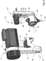
Figure 1 is a schematic perspective view of a toolholder head according to the invention in an assembled configuration; -
Figure 2 is a schematic perspective view of the toolholder head inFigure 1 in a dismantled configuration; -
Figure 3 is a cross section of a driving unit included in the toolholder head inFigure 1 ; -
Figure 4 is a cross section of a toolholder unit included in the toolholder head inFigure 1 ; -
Figure 5 is a further cross section of the toolholder unit inFigure 4 . - With reference to
Figures 1 to 4 there is shown atoolholder head 10 arranged for being slidably supported by a frame of a machine tool, which is not shown, for machining profiled sections, in particular aluminium profiled sections. - The
toolholder head 10 comprises adriving unit 11 and a toolholder unit 12 (Figure 2 ). - The
driving unit 11 comprises afirst frame 13 supporting afirst motor 14, for example an electric motor. - The
first motor 14 comprises afirst drive shaft 15 to an end of which afirst drive pulley 16 is fixed, which is housed in the first frame 13 (Figure 3 ). - The
first drive pulley 16 is connected by afirst strap 18 to a first drivenpulley 17, thefirst strap 18 and the first drivenpulley 17 being housed in thefirst frame 13. - The first driven
pulley 17 comprises afirst seat 19 having a substantially frustum conical shape. Inside thefirst seat 19 there is further provided ascrew 20 extending substantially parallel to a first rotation axis X of the first drivenpulley 17. - The
screw 20 serves to connect stably each other thedriving unit 11 and thetoolholder unit 12 and to act as an extracting element when thetoolholder unit 12 is separated from thedriving unit 11. - Two
further screws frame 13 of thedriving unit 11 and intended for interacting with the drivenpulley 17 to lock the drivenpulley 17, such as to be able to connect thetoolholder unit 12 to thedriving unit 11 and separate thetoolholder unit 12 from thedriving unit 11 without the pull of thestrap 18 being affected. This makes it unnecessary to have to check and possibly adjust the pull of thestrap 18 each time that thetoolholder unit 12 separates from thedriving unit 11 or connects thereto. This makes the operations of separating/connecting the two units particularly rapid. - The
driving unit 11 further comprises a pneumatic toolconnecting/disconnectingdevice 21, which is not disclosed in detail as it is of known type. - Also, the
driving unit 11 comprises first lubricating conduits, which are not shown, for conveying a lubricant to atool 31, for example a milling unit, and to rotating parts of thetoolholder head 10. - The
aforesaid toolholder unit 12 comprises asecond frame 22 supporting asecond motor 23, for example an electric motor (Figure 2 ). - The
second motor 23 comprises asecond drive shaft 24 to an end of which asecond drive pulley 25 is fixed, which is housed in the second frame 22 (Figure 4 ). - The
second drive pulley 25 is connected by asecond strap 26 to a second drivenpulley 27, thesecond strap 26 and the second drivenpulley 27 being housed in thesecond frame 22. A first drivenshaft 28 is fixed to the second drivenpulley 27 by a first end 33 thereof. - The first driven
shaft 28 supports alubricant rotating distributor 29, which is not disclosed in detail inasmuch as it is of known type. - The
toolholder unit 12 further comprises atool support 30 that is rotatably supported by thesecond frame 22. - The
tool support 30 is arranged for rotatingly supporting thetool 31 around its own axis of rotation W. - Further, as will be disclosed better below, the
tool support 30 is rotatable around a second axis Y by thesecond motor 23. - In particular, the second axis Y substantially coincides, when the
toolholder head 10 is in the configuration inFigure 1 , with the first axis X. - The
tool support 30 is connected, via aflange 32, to asecond end 34 of the first drivenshaft 28. - Further, the
tool support 30 supports asleeve 35 rotatably. In particular, thesleeve 35 supports at one end thetool 31 and at a further end ashank 36 arranged for interacting with the pneumatic tool-disconnectingdevice 21. - A
first gear 37 is fixed to thesleeve 35, thefirst gear 37 being arranged in use for rotating substantially parallel to the rotation axis W. - The
first gear 37 engages asecond gear 38, which is rotatably supported, substantially parallel to the second axis Y, by thetool support 30. - A second driven
shaft 40 is fixed to thesecond gear 38. - At one end of the driven
shaft 40 opposite the second gear 38 afirst joint 39, having a substantially frustum conical shape, is provided that is arranged for coupling in a shapingly coupled manner with thefirst seat 19. Thejoint 39 is further provided with a threaded seat 45 (Figure 2 ), in which thescrew 20 can engage to make stable and precise coupling between thedriving unit 11 and thetoolholder unit 12. - In use, the
first joint 39, thefirst seat 19 and thescrew 20 achieve a first quick joint connection between thedriving unit 11 and thetoolholder unit 12. - Further, the
toolholder unit 12 comprises secondlubricating conduits 41 to convey the lubricant to thetool 31, to the rotating parts of thetoolholder head 10 and to the rotating distributor 29 (Figure 5 ). - The second
lubricating conduits 41 are connected to asecond seat 42 arranged for engaging with a corresponding second joint, which is not shown, which is connected to the aforesaid first lubricating conduits, such as to constitute an integrated lubricating system with thedriving unit 11. In use, the second joint and thesecond seat 42 achieve a second quick joint connection between thedriving unit 11 and thetoolholder unit 12. - From the
toolholder unit 12further pins 43 further project that are arranged for being inserted into corresponding further seat elements 44 obtained in the driving unit 11 (Figure 2 ). - This enables the
driving unit 11 to be coupled precisely with thetoolholder unit 12. - The
toolholder head 10 further comprises sensors, which are not shown, which are positioned in thedriving unit 11 and are arranged for controlling the movements of thetool support 30 around the second axis Y, said sensors being able to be associated with a numeric control device for managing the angle of tilt of the tool (31) around the axis Y. - In use, the
first motor 14 rotates thefirst drive pulley 16, which rotates the first drivenpulley 17 by means of thefirst strap 18. - The first driven
pulley 17, which is removably connected to the second drivenshaft 40 by the quick joint achieved by thefirst seat 19, by thescrew 20 and by thefirst joint 39, rotates the second drivenshaft 40. - The second driven
shaft 40 in turn rotates thetool 31 by thesecond gear 38 and thefirst gear 37. - Further, in use, it is possible to rotate the
tool support 30 around the second axis Y. - To do so, it is sufficient to drive the
second motor 23, which rotates thesecond drive pulley 25. - The latter rotates, by means of the
second strap 26, the second drivenpulley 27. - The second driven
pulley 27, by means of the first drivenshaft 28, rotates thetool support 30. - It should be noted that the
toolholder head 10 is more flexible than known toolholder heads. - In fact, the first joint 39-
first seat 19 and secondjointsecond seat 42 pairs enable the drivingunit 11 to be connected to/disconnected from thetoolholder unit 12, without removing thepulley 17. Further, thescrews unit 11 to be connected to/disconnected from thetoolholder unit 12, without affecting the pull of thestrap 18. - This enables the
toolholder unit 12 to be replaced rapidly in the event of breakage or if it is desired to replace thetoolholder unit 12 with another toolholder unit provided with a different tool support. - This further enables machine downtimes to be reduced if it is necessary to replace the toolholder unit.
- In fact, in this case, it is no longer necessary to remove the
entire toolholder head 10 from the machine tool but it is sufficient to replace thetoolholder unit 12. - It should also be noted that the
first motor 14, thefirst drive pulley 16, the first drivenpulley 17 and thefirst strap 18 of the drivingunit 11, are arranged such as to minimise the overall dimensions of the drivingunit 11 with respect to thetool 31 and to thetool support 30. - In one embodiment of the invention, which is not shown, the
first seat 19 and the first joint 39 may have any shape provided that they achieve a shapingly coupling. - In a further embodiment of the invention, which is not shown, it is possible to use any type of quick joint in place of the first seat 19-first joint 39 and second seat 42-second joint pairs.
- Variations on and/or additions to what has been disclosed above and/or shown in the attached drawings are also possible, without departing from the scope of the claims.
Claims (13)
- Toolholder head (10) for a machine tool for machining elongated elements, comprising a toolholder unit (12) for supporting a tool (31) in such a way that it can be rotated around a first axis (W) and be tilted around a second axis (Y) that is orthogonal with respect to said first axis (W) and a driving unit (11) comprising a first motor (14) for rotating said tool (31) around said first axis of rotation (W), said toolholder unit (12) being provided with a second motor (23) and with motion transmission members (25, 26, 28) that are suitable for tilting said tool (31) around said second axis (Y), characterised in that quick joint connecting means (19, 20, 39, 42) is provided for removably connecting said toolholder unit (12) to said driving unit (11).
- Toolholder head (10) according to claim 1, wherein said quick joint connecting means (19, 20, 39, 42) comprises first quick joint connecting means (19, 20, 39) for removably connecting first motion transmission means (16, 17, 18) included in said driving unit (11) to second motion transmission means (37, 38, 40) included in said toolholder unit (12), said first motion transmission means (16, 17, 18) and said second motion transmission means (37, 38, 40) being arranged for transmitting the motion from said first motor (14) of said driving unit (11) to said tool (31).
- Toolholder head (10) according to claim 2, wherein said first quick joint connecting means (19, 20, 39) comprises a first coupling element (19) associated with said driving unit (11) and a further first coupling element (39) associated with said toolholder unit (12), said first coupling element (19) and said further first coupling element (39) being couplable in a shapingly coupled manner..
- Toolholder head (10) according to claim 3, wherein said first coupling element (19) comprises a first seat (19) and said further first coupling element comprises a first joint element (39) that is insertible into said first seat (19), said first seat (19) and said first joint element (39) having a substantially frustum conical shape.
- Toolholder head (10) according to claim 4, wherein said first seat (19) is obtained in a pulley element (17), of said first motion transmission means (16, 17, 18), connected to said motor (14), and said first joint element (39) is associated with a shaft element (40), of said second motion transmission means (37, 38, 40), connected to said tool (31).
- Toolholder head (10) according to any preceding claim, wherein said quick joint connecting means (19, 20, 39, 42) comprises second quick joint connecting means (42) to connect removably first lubricating means included in said driving unit (11) to second lubricating means (41) included in said toolholder unit (12), such as to constitute a lubricating system integrated with said first lubricating means (41), said first lubricating means and said second lubricating means (41) cooperating to convey a lubricating means to said tool (31) and to rotating parts of said toolholder head (10) .
- Toolholder head (10) according to claim 6, wherein said second quick joint connecting means comprises a second seat (42) and a second joint element that is insertible into said second seat (42), said second seat (42) being obtained in said toolholder unit (12) and said second joint element being associated with said driving unit (11) .
- Toolholder head (10) according to any one of claims 4to 7, wherein said first quick joint connecting means (19, 20, 39) comprises a screw element (20) associated with said first seat (19) and suitable for being coupled with a threaded seat (45) provided in said first joint element (39).
- Toolholder head (10) according to any one of claims 5 to 8, further comprising locking elements (46, 47) suitable for interacting with said pulley element (17) to lock said pulley element (17), said locking elements comprising screw elements (46, 47).
- Toolholder head (10), according to any preceding claim, and further comprising reference means (43, 44) for coupling said driving unit (11) precisely with said toolholder unit (12).
- Toolholder head (10) according to claim 10, wherein said reference means (43, 44) comprises at least one further seat element (44) and at least a further pin element (43) that is insertible into said at least one further seat element (44), said at least one further seat element (44) being obtained in said driving unit (11) and said at least a further pin element (43) being associated with said toolholder unit (12).
- Toolholder head (10) according to any preceding claim, wherein said toolholder unit is provided with disconnecting means (36) suitable for interacting with a connecting/disconnecting device (21) of said tool (31) provided in said driving unit (11).
- Toolholder head (10) according to any preceding claim, further comprising sensors positioned in said driving unit (11) and arranged for controlling the movements of said tool (31) around said second axis (Y), said sensors being associable with a numeric control device that is suitable for managing a tilt angle of the tool (31) around the second axis (Y).
Applications Claiming Priority (1)
| Application Number | Priority Date | Filing Date | Title |
|---|---|---|---|
| ITMO2009A000299A IT1397538B1 (en) | 2009-12-21 | 2009-12-21 | HEAD HOLDER HEAD |
Publications (2)
| Publication Number | Publication Date |
|---|---|
| EP2335865A1 EP2335865A1 (en) | 2011-06-22 |
| EP2335865B1 true EP2335865B1 (en) | 2023-12-20 |
Family
ID=42319292
Family Applications (1)
| Application Number | Title | Priority Date | Filing Date |
|---|---|---|---|
| EP10196338.7A Active EP2335865B1 (en) | 2009-12-21 | 2010-12-21 | Toolholder head |
Country Status (2)
| Country | Link |
|---|---|
| EP (1) | EP2335865B1 (en) |
| IT (1) | IT1397538B1 (en) |
Families Citing this family (3)
| Publication number | Priority date | Publication date | Assignee | Title |
|---|---|---|---|---|
| TWI616273B (en) * | 2016-07-19 | 2018-03-01 | 晉好科技有限公司 | Quick change connetor |
| TWI647052B (en) * | 2017-03-06 | 2019-01-11 | 豪力輝工業股份有限公司 | Machine head device of processing machine |
| CN111036939B (en) * | 2019-12-31 | 2025-04-29 | 科德数控股份有限公司 | An angle attachment head with belt drive |
Family Cites Families (2)
| Publication number | Priority date | Publication date | Assignee | Title |
|---|---|---|---|---|
| DE4027687A1 (en) * | 1990-08-31 | 1992-03-05 | Ott Maschinentechnik | TOOL HOLDER WITH MODULAR STRUCTURE FOR DRIVEN TOOLS FOR USE ON LATHE |
| CN101616765A (en) * | 2007-01-08 | 2009-12-30 | 阿绍克·威施瓦那兹·赛泽 | Actuation system for engaging and disengaging drive connectors of a rotary tool holder drive |
-
2009
- 2009-12-21 IT ITMO2009A000299A patent/IT1397538B1/en active
-
2010
- 2010-12-21 EP EP10196338.7A patent/EP2335865B1/en active Active
Also Published As
| Publication number | Publication date |
|---|---|
| ITMO20090299A1 (en) | 2011-06-22 |
| EP2335865A1 (en) | 2011-06-22 |
| IT1397538B1 (en) | 2013-01-16 |
Similar Documents
| Publication | Publication Date | Title |
|---|---|---|
| CN110370353B (en) | Fixing device for perforating tubular workpiece | |
| CN109128921A (en) | A kind of machinery automation processing turnover device | |
| EP2335865A1 (en) | Toolholder head | |
| CN105935885A (en) | Device with removable accessory and assembly for machining lathe, and machining lathe with digital control | |
| CN108856535B (en) | A logistics cargo box fixing mechanism | |
| JP5123537B2 (en) | Machine tool table equipment | |
| JP5281757B2 (en) | Spindle for attaching vehicle wheel rims to factory machines, especially tire changers | |
| TW202100282A (en) | Inclining and rotating table apparatus | |
| CN108097987A (en) | A kind of numerically controlled lathe knife rest of adjustable cutter height | |
| JP5850971B2 (en) | Tool changer that maintains the connection between the tool magazine and the magazine drive motor during the rotation of the tool magazine | |
| CN109759614A (en) | A multi-angle adjustable drilling machine | |
| CN102134944B (en) | Motorized hinge device for heavy pivoting doors and heavy pivoting door with such a hinge device | |
| CN104400040B (en) | Bore hole and end face processing head | |
| CN202028793U (en) | Rim drilling machine | |
| KR20100001859U (en) | Side tapping device of tapping machine | |
| CN207606908U (en) | A kind of magnetic head production punching fixture | |
| CN106346290A (en) | Drilling machine capable of replacing drilling heads | |
| CN104475815B (en) | Multiaxis cutter adjustment structure | |
| CN216990887U (en) | Positioning tool for mold production and machining | |
| ITMI20080384U1 (en) | DEVICE FOR QUICK CHANGE OF A WORKING ROLLER | |
| CN209478274U (en) | A kind of composite material bead cutter | |
| CN208840640U (en) | One kind can the multi-functional tapping jig of positive counter regulation | |
| CN216176844U (en) | Drilling device for end of busbar | |
| CN212824124U (en) | Hole digger saw bit quick replacement system and hole digger subassembly of saw bit quick release | |
| CN110757729B (en) | Cleaning apparatus |
Legal Events
| Date | Code | Title | Description |
|---|---|---|---|
| PUAI | Public reference made under article 153(3) epc to a published international application that has entered the european phase |
Free format text: ORIGINAL CODE: 0009012 |
|
| AK | Designated contracting states |
Kind code of ref document: A1 Designated state(s): AL AT BE BG CH CY CZ DE DK EE ES FI FR GB GR HR HU IE IS IT LI LT LU LV MC MK MT NL NO PL PT RO RS SE SI SK SM TR |
|
| AX | Request for extension of the european patent |
Extension state: BA ME |
|
| GRAP | Despatch of communication of intention to grant a patent |
Free format text: ORIGINAL CODE: EPIDOSNIGR1 |
|
| 17P | Request for examination filed |
Effective date: 20111222 |
|
| RIC1 | Information provided on ipc code assigned before grant |
Ipc: B23Q 5/04 20060101ALI20120105BHEP Ipc: B23Q 1/54 20060101AFI20120105BHEP |
|
| GRAS | Grant fee paid |
Free format text: ORIGINAL CODE: EPIDOSNIGR3 |
|
| RAP1 | Party data changed (applicant data changed or rights of an application transferred) |
Owner name: EMMEGI S.P.A. |
|
| 19A | Proceedings stayed before grant |
Effective date: 20120911 |
|
| 19A | Proceedings stayed before grant |
Effective date: 20120822 |
|
| 19F | Resumption of proceedings before grant (after stay of proceedings) |
Effective date: 20231102 |
|
| GRAA | (expected) grant |
Free format text: ORIGINAL CODE: 0009210 |
|
| STAA | Information on the status of an ep patent application or granted ep patent |
Free format text: STATUS: THE PATENT HAS BEEN GRANTED |
|
| RAP3 | Party data changed (applicant data changed or rights of an application transferred) |
Owner name: HSD S.P.A. Owner name: EMMEGI S.P.A. |
|
| AK | Designated contracting states |
Kind code of ref document: B1 Designated state(s): AL AT BE BG CH CY CZ DE DK EE ES FI FR GB GR HR HU IE IS IT LI LT LU LV MC MK MT NL NO PL PT RO RS SE SI SK SM TR |
|
| REG | Reference to a national code |
Ref country code: GB Ref legal event code: FG4D |
|
| REG | Reference to a national code |
Ref country code: DE Ref legal event code: R096 Ref document number: 602010069176 Country of ref document: DE |
|
| REG | Reference to a national code |
Ref country code: CH Ref legal event code: EP |
|
| REG | Reference to a national code |
Ref country code: IE Ref legal event code: FG4D |
|
| PG25 | Lapsed in a contracting state [announced via postgrant information from national office to epo] |
Ref country code: GR Free format text: LAPSE BECAUSE OF FAILURE TO SUBMIT A TRANSLATION OF THE DESCRIPTION OR TO PAY THE FEE WITHIN THE PRESCRIBED TIME-LIMIT Effective date: 20240321 |
|
| REG | Reference to a national code |
Ref country code: LT Ref legal event code: MG9D |
|
| PG25 | Lapsed in a contracting state [announced via postgrant information from national office to epo] |
Ref country code: LT Free format text: LAPSE BECAUSE OF FAILURE TO SUBMIT A TRANSLATION OF THE DESCRIPTION OR TO PAY THE FEE WITHIN THE PRESCRIBED TIME-LIMIT Effective date: 20231220 |
|
| REG | Reference to a national code |
Ref country code: NL Ref legal event code: MP Effective date: 20231220 |
|
| PG25 | Lapsed in a contracting state [announced via postgrant information from national office to epo] |
Ref country code: ES Free format text: LAPSE BECAUSE OF FAILURE TO SUBMIT A TRANSLATION OF THE DESCRIPTION OR TO PAY THE FEE WITHIN THE PRESCRIBED TIME-LIMIT Effective date: 20231220 |
|
| PG25 | Lapsed in a contracting state [announced via postgrant information from national office to epo] |
Ref country code: LT Free format text: LAPSE BECAUSE OF FAILURE TO SUBMIT A TRANSLATION OF THE DESCRIPTION OR TO PAY THE FEE WITHIN THE PRESCRIBED TIME-LIMIT Effective date: 20231220 Ref country code: GR Free format text: LAPSE BECAUSE OF FAILURE TO SUBMIT A TRANSLATION OF THE DESCRIPTION OR TO PAY THE FEE WITHIN THE PRESCRIBED TIME-LIMIT Effective date: 20240321 Ref country code: FI Free format text: LAPSE BECAUSE OF FAILURE TO SUBMIT A TRANSLATION OF THE DESCRIPTION OR TO PAY THE FEE WITHIN THE PRESCRIBED TIME-LIMIT Effective date: 20231220 Ref country code: ES Free format text: LAPSE BECAUSE OF FAILURE TO SUBMIT A TRANSLATION OF THE DESCRIPTION OR TO PAY THE FEE WITHIN THE PRESCRIBED TIME-LIMIT Effective date: 20231220 Ref country code: BG Free format text: LAPSE BECAUSE OF FAILURE TO SUBMIT A TRANSLATION OF THE DESCRIPTION OR TO PAY THE FEE WITHIN THE PRESCRIBED TIME-LIMIT Effective date: 20240320 |
|
| REG | Reference to a national code |
Ref country code: AT Ref legal event code: MK05 Ref document number: 1642082 Country of ref document: AT Kind code of ref document: T Effective date: 20231220 |
|
| PG25 | Lapsed in a contracting state [announced via postgrant information from national office to epo] |
Ref country code: NL Free format text: LAPSE BECAUSE OF FAILURE TO SUBMIT A TRANSLATION OF THE DESCRIPTION OR TO PAY THE FEE WITHIN THE PRESCRIBED TIME-LIMIT Effective date: 20231220 |
|
| PG25 | Lapsed in a contracting state [announced via postgrant information from national office to epo] |
Ref country code: SE Free format text: LAPSE BECAUSE OF FAILURE TO SUBMIT A TRANSLATION OF THE DESCRIPTION OR TO PAY THE FEE WITHIN THE PRESCRIBED TIME-LIMIT Effective date: 20231220 Ref country code: RS Free format text: LAPSE BECAUSE OF FAILURE TO SUBMIT A TRANSLATION OF THE DESCRIPTION OR TO PAY THE FEE WITHIN THE PRESCRIBED TIME-LIMIT Effective date: 20231220 Ref country code: NO Free format text: LAPSE BECAUSE OF FAILURE TO SUBMIT A TRANSLATION OF THE DESCRIPTION OR TO PAY THE FEE WITHIN THE PRESCRIBED TIME-LIMIT Effective date: 20240320 Ref country code: NL Free format text: LAPSE BECAUSE OF FAILURE TO SUBMIT A TRANSLATION OF THE DESCRIPTION OR TO PAY THE FEE WITHIN THE PRESCRIBED TIME-LIMIT Effective date: 20231220 Ref country code: LV Free format text: LAPSE BECAUSE OF FAILURE TO SUBMIT A TRANSLATION OF THE DESCRIPTION OR TO PAY THE FEE WITHIN THE PRESCRIBED TIME-LIMIT Effective date: 20231220 Ref country code: HR Free format text: LAPSE BECAUSE OF FAILURE TO SUBMIT A TRANSLATION OF THE DESCRIPTION OR TO PAY THE FEE WITHIN THE PRESCRIBED TIME-LIMIT Effective date: 20231220 |
|
| PG25 | Lapsed in a contracting state [announced via postgrant information from national office to epo] |
Ref country code: IS Free format text: LAPSE BECAUSE OF FAILURE TO SUBMIT A TRANSLATION OF THE DESCRIPTION OR TO PAY THE FEE WITHIN THE PRESCRIBED TIME-LIMIT Effective date: 20240420 |
|
| REG | Reference to a national code |
Ref country code: DE Ref legal event code: R119 Ref document number: 602010069176 Country of ref document: DE |
|
| PG25 | Lapsed in a contracting state [announced via postgrant information from national office to epo] |
Ref country code: AT Free format text: LAPSE BECAUSE OF FAILURE TO SUBMIT A TRANSLATION OF THE DESCRIPTION OR TO PAY THE FEE WITHIN THE PRESCRIBED TIME-LIMIT Effective date: 20231220 Ref country code: CZ Free format text: LAPSE BECAUSE OF FAILURE TO SUBMIT A TRANSLATION OF THE DESCRIPTION OR TO PAY THE FEE WITHIN THE PRESCRIBED TIME-LIMIT Effective date: 20231220 |
|
| PG25 | Lapsed in a contracting state [announced via postgrant information from national office to epo] |
Ref country code: SK Free format text: LAPSE BECAUSE OF FAILURE TO SUBMIT A TRANSLATION OF THE DESCRIPTION OR TO PAY THE FEE WITHIN THE PRESCRIBED TIME-LIMIT Effective date: 20231220 |
|
| PG25 | Lapsed in a contracting state [announced via postgrant information from national office to epo] |
Ref country code: SM Free format text: LAPSE BECAUSE OF FAILURE TO SUBMIT A TRANSLATION OF THE DESCRIPTION OR TO PAY THE FEE WITHIN THE PRESCRIBED TIME-LIMIT Effective date: 20231220 Ref country code: SK Free format text: LAPSE BECAUSE OF FAILURE TO SUBMIT A TRANSLATION OF THE DESCRIPTION OR TO PAY THE FEE WITHIN THE PRESCRIBED TIME-LIMIT Effective date: 20231220 Ref country code: RO Free format text: LAPSE BECAUSE OF FAILURE TO SUBMIT A TRANSLATION OF THE DESCRIPTION OR TO PAY THE FEE WITHIN THE PRESCRIBED TIME-LIMIT Effective date: 20231220 Ref country code: IS Free format text: LAPSE BECAUSE OF FAILURE TO SUBMIT A TRANSLATION OF THE DESCRIPTION OR TO PAY THE FEE WITHIN THE PRESCRIBED TIME-LIMIT Effective date: 20240420 Ref country code: EE Free format text: LAPSE BECAUSE OF FAILURE TO SUBMIT A TRANSLATION OF THE DESCRIPTION OR TO PAY THE FEE WITHIN THE PRESCRIBED TIME-LIMIT Effective date: 20231220 Ref country code: CZ Free format text: LAPSE BECAUSE OF FAILURE TO SUBMIT A TRANSLATION OF THE DESCRIPTION OR TO PAY THE FEE WITHIN THE PRESCRIBED TIME-LIMIT Effective date: 20231220 Ref country code: AT Free format text: LAPSE BECAUSE OF FAILURE TO SUBMIT A TRANSLATION OF THE DESCRIPTION OR TO PAY THE FEE WITHIN THE PRESCRIBED TIME-LIMIT Effective date: 20231220 |
|
| REG | Reference to a national code |
Ref country code: CH Ref legal event code: PL |
|
| PG25 | Lapsed in a contracting state [announced via postgrant information from national office to epo] |
Ref country code: PT Free format text: LAPSE BECAUSE OF FAILURE TO SUBMIT A TRANSLATION OF THE DESCRIPTION OR TO PAY THE FEE WITHIN THE PRESCRIBED TIME-LIMIT Effective date: 20240422 Ref country code: PL Free format text: LAPSE BECAUSE OF FAILURE TO SUBMIT A TRANSLATION OF THE DESCRIPTION OR TO PAY THE FEE WITHIN THE PRESCRIBED TIME-LIMIT Effective date: 20231220 |
|
| PG25 | Lapsed in a contracting state [announced via postgrant information from national office to epo] |
Ref country code: LU Free format text: LAPSE BECAUSE OF NON-PAYMENT OF DUE FEES Effective date: 20231221 |
|
| REG | Reference to a national code |
Ref country code: BE Ref legal event code: MM Effective date: 20231231 |
|
| PG25 | Lapsed in a contracting state [announced via postgrant information from national office to epo] |
Ref country code: PT Free format text: LAPSE BECAUSE OF FAILURE TO SUBMIT A TRANSLATION OF THE DESCRIPTION OR TO PAY THE FEE WITHIN THE PRESCRIBED TIME-LIMIT Effective date: 20240422 Ref country code: PL Free format text: LAPSE BECAUSE OF FAILURE TO SUBMIT A TRANSLATION OF THE DESCRIPTION OR TO PAY THE FEE WITHIN THE PRESCRIBED TIME-LIMIT Effective date: 20231220 Ref country code: LU Free format text: LAPSE BECAUSE OF NON-PAYMENT OF DUE FEES Effective date: 20231221 |
|
| PG25 | Lapsed in a contracting state [announced via postgrant information from national office to epo] |
Ref country code: MC Free format text: LAPSE BECAUSE OF FAILURE TO SUBMIT A TRANSLATION OF THE DESCRIPTION OR TO PAY THE FEE WITHIN THE PRESCRIBED TIME-LIMIT Effective date: 20231220 |
|
| REG | Reference to a national code |
Ref country code: IE Ref legal event code: MM4A |
|
| PG25 | Lapsed in a contracting state [announced via postgrant information from national office to epo] |
Ref country code: IE Free format text: LAPSE BECAUSE OF NON-PAYMENT OF DUE FEES Effective date: 20231221 Ref country code: DE Free format text: LAPSE BECAUSE OF NON-PAYMENT OF DUE FEES Effective date: 20240702 |
|
| PG25 | Lapsed in a contracting state [announced via postgrant information from national office to epo] |
Ref country code: DK Free format text: LAPSE BECAUSE OF FAILURE TO SUBMIT A TRANSLATION OF THE DESCRIPTION OR TO PAY THE FEE WITHIN THE PRESCRIBED TIME-LIMIT Effective date: 20231220 |
|
| PG25 | Lapsed in a contracting state [announced via postgrant information from national office to epo] |
Ref country code: BE Free format text: LAPSE BECAUSE OF NON-PAYMENT OF DUE FEES Effective date: 20231231 |
|
| PG25 | Lapsed in a contracting state [announced via postgrant information from national office to epo] |
Ref country code: CH Free format text: LAPSE BECAUSE OF NON-PAYMENT OF DUE FEES Effective date: 20231231 |
|
| PLBE | No opposition filed within time limit |
Free format text: ORIGINAL CODE: 0009261 |
|
| STAA | Information on the status of an ep patent application or granted ep patent |
Free format text: STATUS: NO OPPOSITION FILED WITHIN TIME LIMIT |
|
| PG25 | Lapsed in a contracting state [announced via postgrant information from national office to epo] |
Ref country code: SI Free format text: LAPSE BECAUSE OF FAILURE TO SUBMIT A TRANSLATION OF THE DESCRIPTION OR TO PAY THE FEE WITHIN THE PRESCRIBED TIME-LIMIT Effective date: 20231220 |
|
| PG25 | Lapsed in a contracting state [announced via postgrant information from national office to epo] |
Ref country code: SI Free format text: LAPSE BECAUSE OF FAILURE TO SUBMIT A TRANSLATION OF THE DESCRIPTION OR TO PAY THE FEE WITHIN THE PRESCRIBED TIME-LIMIT Effective date: 20231220 Ref country code: IE Free format text: LAPSE BECAUSE OF NON-PAYMENT OF DUE FEES Effective date: 20231221 Ref country code: DK Free format text: LAPSE BECAUSE OF FAILURE TO SUBMIT A TRANSLATION OF THE DESCRIPTION OR TO PAY THE FEE WITHIN THE PRESCRIBED TIME-LIMIT Effective date: 20231220 Ref country code: DE Free format text: LAPSE BECAUSE OF NON-PAYMENT OF DUE FEES Effective date: 20240702 Ref country code: CH Free format text: LAPSE BECAUSE OF NON-PAYMENT OF DUE FEES Effective date: 20231231 Ref country code: BE Free format text: LAPSE BECAUSE OF NON-PAYMENT OF DUE FEES Effective date: 20231231 |
|
| 26N | No opposition filed |
Effective date: 20240923 |
|
| GBPC | Gb: european patent ceased through non-payment of renewal fee |
Effective date: 20240320 |
|
| PG25 | Lapsed in a contracting state [announced via postgrant information from national office to epo] |
Ref country code: GB Free format text: LAPSE BECAUSE OF NON-PAYMENT OF DUE FEES Effective date: 20240320 |
|
| PGFP | Annual fee paid to national office [announced via postgrant information from national office to epo] |
Ref country code: FR Payment date: 20241226 Year of fee payment: 15 |
|
| PG25 | Lapsed in a contracting state [announced via postgrant information from national office to epo] |
Ref country code: GB Free format text: LAPSE BECAUSE OF NON-PAYMENT OF DUE FEES Effective date: 20240320 |
|
| PG25 | Lapsed in a contracting state [announced via postgrant information from national office to epo] |
Ref country code: CY Free format text: LAPSE BECAUSE OF FAILURE TO SUBMIT A TRANSLATION OF THE DESCRIPTION OR TO PAY THE FEE WITHIN THE PRESCRIBED TIME-LIMIT; INVALID AB INITIO Effective date: 20101221 |
|
| PG25 | Lapsed in a contracting state [announced via postgrant information from national office to epo] |
Ref country code: HU Free format text: LAPSE BECAUSE OF FAILURE TO SUBMIT A TRANSLATION OF THE DESCRIPTION OR TO PAY THE FEE WITHIN THE PRESCRIBED TIME-LIMIT; INVALID AB INITIO Effective date: 20101221 |
|
| PG25 | Lapsed in a contracting state [announced via postgrant information from national office to epo] |
Ref country code: TR Free format text: LAPSE BECAUSE OF FAILURE TO SUBMIT A TRANSLATION OF THE DESCRIPTION OR TO PAY THE FEE WITHIN THE PRESCRIBED TIME-LIMIT Effective date: 20231220 |
|
| PGFP | Annual fee paid to national office [announced via postgrant information from national office to epo] |
Ref country code: IT Payment date: 20251117 Year of fee payment: 16 |