EP2335816A2 - Vorrichtung zum Mischen von heißen Strömen - Google Patents
Vorrichtung zum Mischen von heißen Strömen Download PDFInfo
- Publication number
- EP2335816A2 EP2335816A2 EP10015219A EP10015219A EP2335816A2 EP 2335816 A2 EP2335816 A2 EP 2335816A2 EP 10015219 A EP10015219 A EP 10015219A EP 10015219 A EP10015219 A EP 10015219A EP 2335816 A2 EP2335816 A2 EP 2335816A2
- Authority
- EP
- European Patent Office
- Prior art keywords
- inner tube
- mixing
- mixing device
- air supply
- air
- Prior art date
- Legal status (The legal status is an assumption and is not a legal conclusion. Google has not performed a legal analysis and makes no representation as to the accuracy of the status listed.)
- Withdrawn
Links
Images

Classifications
-
- B—PERFORMING OPERATIONS; TRANSPORTING
- B01—PHYSICAL OR CHEMICAL PROCESSES OR APPARATUS IN GENERAL
- B01F—MIXING, e.g. DISSOLVING, EMULSIFYING OR DISPERSING
- B01F23/00—Mixing according to the phases to be mixed, e.g. dispersing or emulsifying
- B01F23/10—Mixing gases with gases
-
- B—PERFORMING OPERATIONS; TRANSPORTING
- B01—PHYSICAL OR CHEMICAL PROCESSES OR APPARATUS IN GENERAL
- B01F—MIXING, e.g. DISSOLVING, EMULSIFYING OR DISPERSING
- B01F25/00—Flow mixers; Mixers for falling materials, e.g. solid particles
- B01F25/30—Injector mixers
- B01F25/31—Injector mixers in conduits or tubes through which the main component flows
- B01F25/314—Injector mixers in conduits or tubes through which the main component flows wherein additional components are introduced at the circumference of the conduit
- B01F25/3142—Injector mixers in conduits or tubes through which the main component flows wherein additional components are introduced at the circumference of the conduit the conduit having a plurality of openings in the axial direction or in the circumferential direction
- B01F25/31423—Injector mixers in conduits or tubes through which the main component flows wherein additional components are introduced at the circumference of the conduit the conduit having a plurality of openings in the axial direction or in the circumferential direction with a plurality of perforations in the circumferential direction only and covering the whole circumference
Definitions
- the invention relates to a device for mixing hot gas streams, in particular in an afterburner (anode tail gas oxidizer - ATO) of a fuel cell system.
- the anode and cathode of a fuel cell per a line a fuel gas and air is supplied via another line, wherein the anode, the fuel gas is supplied.
- the fuel cell parts of these gas streams react.
- this residual gas can still be used energetically.
- the remaining fuel gas is combined with excess air by the anode and cathode exhaust gas line merged and this mixture is fed to a Naschbrenner.
- the gas is completely burned. This creates the problem that the mixture may be flammable and premature ignition should be avoided. Therefore, the mixture takes place as late as possible.
- the object of the present invention is therefore to provide a device for mixing gas streams (eg air and anode residual gas) which ensures optimum mixing with short residence times of these gas streams in the mixing zone.
- gas streams eg air and anode residual gas
- the mixing device should be made compact and small and minimize pressure losses.
- a mixing device for mixing hot gas streams, an air supply or anode residual gas supply is passed into an inner tube, the other supply of air supply or anode residual gas supply is passed into an outer tube arranged concentrically to the inner ear, wherein the outer tube along a certain length along of the inner tube extends. Holes are present in the inner tube in the region of the coaxial extension of the inner tube with the outer tube. An output line of the mixing device from the inner tube is arranged on the side facing away from the air supply side of the inner tube. This ensures that the mixing of the two gas streams is late, but intense.
- the bores can be arranged close to the outlet of the mixing device in order to avoid that large amounts of ignitable mixture can form. If all holes are arranged on a circular line, the mixing is homogeneous.
- FIG. 1 shows the mixing device according to the invention with air supply 2 and an anode residual gas supply 1.
- Air supply 2 and anode residual gas supply 1 are here first performed perpendicular to each other in the mixing device.
- the anode residual gas contains combustible components.
- the air supply 2 is passed into a cylindrical inner tube 4.
- an extension jump 5 5.
- the anode residual gas feed 1 is passed into a concentric with the inner tube 4 extending outer tube 3, wherein the outer tube 3 extends over a certain length along the inner tube 4.
- About holes 7 in the inner tube 3 in the region of the coaxial extension of the inner tube 3 with the outer tube 3, the interior of the inner tube 3 are connected to the interior of the outer tube 4.
- the holes 7 are located on a circular line in the vicinity of an output line 6 of the mixing device on the side facing away from the air supply 2 of the inner tube. 4
- the anode residual gas is passed in operation through the holes 7, which may also be designed as slots, vertically into the air flow, resulting in a turbulent mixing. Until entry into the following honeycomb or pore structure with afterburner sufficient mixing and velocity distribution of air and anode residual gas is ensured.
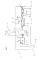
- FIG. 2 schematically shows a fuel cell system with a reformer 9, a fuel cell stack 10, an afterburner 8, a starting burner 11, an air preheater 12, a desulfurization 13 and an inverter 14 in a vacuum chamber 15. Natural gas passes through a natural gas line 16 and air via an air line 17 in the system.
- the afterburner 8, the mixing device 18 according to the invention is connected upstream.
- the mixing device 18 is part of the afterburner 8, which is supplied simultaneously with hot desulfurized anode residual gas and hot air.
- the air and anode residual gas volume flows can be varied for process optimization. This can be done by means of variable conveyors (pumps, fans) or valves as actuators.
- the process quality is determined directly by means of suitable gas sensors and / or indirectly, for example via mass or volume flows and process-relevant temperatures.
- the device for mixing gas streams such as air and anode residual gas
- optimal mixing of the gas streams is ensured.
- the design of the mixing device allows a compact and small design.
- a uniform velocity distribution before entering the honeycomb structure of the premixing chamber with the lowest possible pressure loss is also ensured.
Landscapes
- Chemical & Material Sciences (AREA)
- Chemical Kinetics & Catalysis (AREA)
- Fuel Cell (AREA)
Abstract
Description
- Die Erfindung bezieht sich auf eine Vorrichtung zum Mischen von heißen Gasströmen insbesondere bei einem Nachbrenner (Anode Tailgas Oxidizer - ATO) eines Brennstoffzellensystems.
- Bei Brennstoffzellensystemen wird der Anode und Kathode einer Brennstoffzelle je über eine Leitung ein Brenngas und über eine andere Leitung Luft zugeführt, wobei der Anode das Brenngas zugeführt wird. In der Brennstoffzelle reagieren Teile dieser Gasströme. Es bleibt jedoch noch ein Restanteil des Brenngases übrig. Dieses Restgas kann noch energetisch verwendet werden. Gemäß dem Stand der Technik wird das restliche Brenngas mit überschüssiger Luft zusammengeführt, indem die Anoden- und Kathodenabgasleitung zusammengeführt und dieses Gemisch einem Naschbrenner zugeführt wird. Im Nachbrenner wird das Gas vollständig verbrannt. Hierbei entsteht das Problem, dass das Gemisch zündfähig sein kann und eine vorzeitige Entzündung vermieden werden soll. Daher erfolgt die Mischung möglichst spät. Hierdurch ergibt sich jedoch das Problem, dass die für die vollständige Verbrennung notwendige Durchmischung oft nicht gewährleistet ist.
- Aufgabe der vorliegenden Erfindung ist es daher, eine Vorrichtung zum Mischen von Gasströmen (z.B. Luft und Anoden-Restgas) zur Verfügung zu stellen, die eine optimale Durchmischung bei kurzen Verweilzeiten dieser Gasströme in der Mischzone sicherstellt. Zugleich soll die Mischvorrichtung kompakt und klein ausgeführt sein sowie Druckverluste minimieren.
- Diese Aufgabe wird durch eine Mischvorrichtung gemäß den Merkmalen des Anspruchs 1 gelöst. So wird bei der erfindungsgemäßen Mischvorrichtung zum Mischen von heißen Gasströmen eine Luftzuführung oder Anoden-Restgaszuführung in ein Innenrohr geleitet, die andere Zuführung der Luftzuführung oder Anoden-Restgaszuführung wird in ein konzentrisch zum Innerohr angeordneten Außenrohr geleitet, wobei das Außenrohr sich über eine bestimmte Länge entlang des Innenrohrs erstreckt. Bohrungen sind im Innenrohr im Bereich der koaxialen Erstreckung des Innenrohrs mit dem Außenrohr vorhanden. Eine Ausgangsleitung der Mischvorrichtung aus dem Innenrohr ist auf der der Luftzuführung abgewandten Seite des Innenrohrs angeordnet. Hierdurch wird erreicht, dass die Vermischung der beiden Gasströme spät, aber intensiv erfolgt.
- Vorteilhafte Ausgestaltungen ergeben sich gemäß den Merkmalen der abhängigen Ansprüche. So können einerseits die Bohrungen nahe am Ausgang der Mischeinrichtung angeordnet sein, um zu vermieden, dass sich große Mengen zündfähigen Gemischs bilden können. Sind alle Bohrungen auf einer Kreislinie angeordnet, so ist die Vermischung homogen.
- Die Erfindung wird nun anhand der folgenden Figuren detailliert erläutert. Hierbei zeigen
- Fig. 1
- einen Querschnitt der erfindungsgemäße Vorrichtung und
- Fig. 2
- eine schematische Darstellung eines Brennstoffzellensystems.
-
Figur 1 zeigt die erfindungsgemäße Mischvorrichtung mit Luftzuführung 2 und einer Anoden-Restgaszuführung 1. Luftzuführung 2 und Anoden-Restgaszuführung 1 werden hierbei zunächst senkrecht zueinander in die Mischvorrichtung geführt. Das Anoden-Restgas enthält verbrennbare Komponenten. Die Luftzuführung 2 wird in ein zylindrisches Innenrohr 4 geleitet. Hierbei befindet sich beim Übergang von der Luftzuführung 2 zum zylindrischen Innenrohr 4 ein Erweiterungssprung 5. Die Anoden-Restgaszuführung 1 wird in ein konzentrisch zum Innerohr 4 verlaufendes Außenrohr 3 geleitet, wobei das Außenrohr 3 sich über eine bestimmte Länge entlang des Innenrohrs 4 erstreckt. Über Bohrungen 7 im Innenrohr 3 im Bereich der koaxialen Erstreckung des Innenrohrs 3 mit dem Außenrohr 3 sind das Innere des Innenrohrs 3 mit dem Inneren des Außenrohrs 4 verbunden. Die Bohrungen 7 befinden sich auf einer Kreislinie in der Nähe einer Ausgangsleitung 6 der Mischvorrichtung auf der der Luftzuführung 2 abgewandten Seite des Innenrohrs 4. - Das Anoden-Restgas wird im Betrieb durch die Bohrungen 7, die auch als Schlitze ausgelegt sein können, senkrecht in den Luftstrom geleitet, wodurch es zu einer turbulenten Durchmischung kommt. Bis zum Eintritt in die folgende Waben- oder Porenstruktur mit Nachbrenner wird eine ausreichende Vermischung und Geschwindigkeitsverteilung von Luft und Anoden-Restgas gewährleistet.
-
Figur 2 zeigt schematisch eine Brennstoffzellenanlage mit einem Reformer 9, einem Brennstoffzellen-Stack 10, einem Nachbrenner 8, einem Startbrenner 11, einem Luftvorwärmer 12, einer Entschwefelung 13 und einem Inverter 14 in einer Unterdruckkammer 15. Erdgas gelangt über eine Erdgasleitung 16 und Luft über eine Luftleitung 17 in das System. Dem Nachbrenner 8 ist die erfindungsgemäße Mischvorrichtung 18 vorgeschaltet. - Die Mischvorrichtung 18 ist Bestandteil des Nachbrenners 8, der gleichzeitig mit heißem entschwefeltem Anoden-Restgas und heißer Luft versorgt wird. Die Luft- und Anoden-Restgas-Volumenströme können zur Prozessoptimierung variiert werden. Hierzu kann mittels variabler Fördereinrichtungen (Pumpen, Gebläse) oder Ventilen als Aktoren geschehen. Die Prozessgüte wird direkt mittels geeigneten Gassensoren und / oder indirekt z.B. über Massen- oder Volumenströme sowie prozessrelevante Temperaturen bestimmt.
- Durch die Vorrichtung zum Mischen von Gasströmen wie Luft und Anoden-Restgas wird eine optimale Durchmischung der Gasströme sicherstellt. Gleichzeitig erlaubt die Ausbildung der Mischvorrichtung eine kompakte und kleine Bauform. Eine gleichmäßige Geschwindigkeitsverteilung vor dem Eintritt in die Wabenstruktur der Vormischkammer bei möglichst geringem Druckverlust ist ebenfalls sichergestellt. Durch die Führung des Luftstroms über einen Erweiterungssprung vor der Mischung mit dem Anoden-Restgas wird einerseits der Turbulenzgrad erhöht und andererseits die Geschwindigkeit des Luftstroms verändert. Der Luftstrom kann aber auch ohne einen Erweiterungsstrom zugeführt werden.
Claims (3)
- Mischvorrichtung zum Mischen von heißen Gasströmen, insbesondere für einen Nachbrenner eines Brennstoffzellensystems, mit einer Luftzuführung (2) und einer Anoden-Restgaszuführung (1), dadurch gekennzeichnet, dass die Luftzuführung (2) oder Anoden-Restgaszuführung (1) in ein Innenrohr (4) geleitet wird, die andere Zuführung der Luftzuführung (2) oder Anoden-Restgaszuführung (1) in ein konzentrisch zum Innerohr (4) angeordneten Außenrohr (3) geleitet wird, wobei das Außenrohr (3) sich über eine bestimmte Länge entlang des Innenrohrs (4) erstreckt, Bohrungen (7) im Innenrohr (3) im Bereich der koaxialen Erstreckung des Innenrohrs (3) mit dem Außenrohr (3) vorhanden sind und eine Ausgangsleitung (6) der Mischvorrichtung aus dem Innenrohr (4) auf der der Luftzuführung (2) abgewandten Seite des Innenrohrs (4) vorhanden ist.
- Mischvorrichtung nach Anspruch 1, dadurch gekennzeichnet, dass die Bohrungen (7) nahe der Ausgangsleitung (6) angeordnet sind.
- Mischvorrichtung nach Anspruch 1 oder 2, dadurch gekennzeichnet, dass die Bohrungen (7) auf einer Kreislinie angeordnet sind.
Applications Claiming Priority (1)
| Application Number | Priority Date | Filing Date | Title |
|---|---|---|---|
| AT19842009 | 2009-12-15 |
Publications (2)
| Publication Number | Publication Date |
|---|---|
| EP2335816A2 true EP2335816A2 (de) | 2011-06-22 |
| EP2335816A3 EP2335816A3 (de) | 2012-02-29 |
Family
ID=43768921
Family Applications (1)
| Application Number | Title | Priority Date | Filing Date |
|---|---|---|---|
| EP10015219A Withdrawn EP2335816A3 (de) | 2009-12-15 | 2010-12-02 | Vorrichtung zum Mischen von heißen Strömen |
Country Status (2)
| Country | Link |
|---|---|
| EP (1) | EP2335816A3 (de) |
| DE (1) | DE102010053263A1 (de) |
Cited By (2)
| Publication number | Priority date | Publication date | Assignee | Title |
|---|---|---|---|---|
| CN113669761A (zh) * | 2021-08-13 | 2021-11-19 | 上海市特种设备监督检验技术研究院 | 一种天然气加氢燃烧混合装置 |
| AT525431B1 (de) * | 2021-11-25 | 2023-04-15 | Avl List Gmbh | Mischvorrichtung für ein Vermischen von zumindest Anodenabgas und Kathodenabgas aus einem Brennstoffzellenstapel eines Brennstoffzellensystems |
Family Cites Families (6)
| Publication number | Priority date | Publication date | Assignee | Title |
|---|---|---|---|---|
| US4761077A (en) * | 1987-09-28 | 1988-08-02 | Barrett, Haentjens & Co. | Mixing apparatus |
| JP2000213681A (ja) * | 1999-01-27 | 2000-08-02 | Toshiba Corp | 流体混合継手 |
| FR2804045B1 (fr) * | 2000-01-25 | 2002-03-29 | Air Liquide | Dispositif de melange d'un gaz secondaire dans un gaz principal |
| US7901128B2 (en) * | 2004-07-20 | 2011-03-08 | Dow Global Technologies Llc | Tapered aperture multi-tee mixer |
| CN101209405B (zh) * | 2006-12-27 | 2013-08-28 | 宁波万华聚氨酯有限公司 | 一种孔射流式喷射反应器 |
| EP2179985B1 (de) * | 2007-08-21 | 2013-04-10 | Ningbo Wanhua Polyurethanes Co., Ltd. | Mit strömungsleitungen ausgestatteter jetreaktor, verfahren zur herstellung von isocyanaten mittels eines solchen reaktors |
-
2010
- 2010-12-02 EP EP10015219A patent/EP2335816A3/de not_active Withdrawn
- 2010-12-02 DE DE102010053263A patent/DE102010053263A1/de not_active Withdrawn
Non-Patent Citations (1)
| Title |
|---|
| None |
Cited By (3)
| Publication number | Priority date | Publication date | Assignee | Title |
|---|---|---|---|---|
| CN113669761A (zh) * | 2021-08-13 | 2021-11-19 | 上海市特种设备监督检验技术研究院 | 一种天然气加氢燃烧混合装置 |
| AT525431B1 (de) * | 2021-11-25 | 2023-04-15 | Avl List Gmbh | Mischvorrichtung für ein Vermischen von zumindest Anodenabgas und Kathodenabgas aus einem Brennstoffzellenstapel eines Brennstoffzellensystems |
| AT525431A4 (de) * | 2021-11-25 | 2023-04-15 | Avl List Gmbh | Mischvorrichtung für ein Vermischen von zumindest Anodenabgas und Kathodenabgas aus einem Brennstoffzellenstapel eines Brennstoffzellensystems |
Also Published As
| Publication number | Publication date |
|---|---|
| DE102010053263A1 (de) | 2011-06-16 |
| EP2335816A3 (de) | 2012-02-29 |
Similar Documents
| Publication | Publication Date | Title |
|---|---|---|
| EP2329196B1 (de) | Brenner und verfahren zum betrieb eines brenners | |
| EP1840465A2 (de) | Brennersystem mit gestufter Brennstoff-Eindüsung | |
| EP3246557A1 (de) | Raketenantriebssystem und verfahren zum betreiben eines raketenantriebssystems | |
| WO2003022422A1 (de) | System zum umsetzen von brennstoff und luft zu reformat und verfahren zur montage eines solchen systems | |
| AT522484A4 (de) | SOEC-System und Verfahren zum Betreiben eines SOEC-Systems | |
| EP3580801A1 (de) | Startbrenner für ein brennstoffzellensystem | |
| EP0907868A1 (de) | Brenner | |
| DE102010053263A1 (de) | Vorrichtung zum Mischen von heißen Gasströmen | |
| EP3246558B1 (de) | Verfahren zum betreiben eines raketenantriebssystems und raketenantriebssystem | |
| EP2912374B1 (de) | Verfahren zum erzeugen von wasserdampf | |
| WO2008000217A1 (de) | Brennstoffzellensystem | |
| DE102011083407B4 (de) | Restgasbrenner | |
| DE102007031782A1 (de) | Verfahren und Vorrichtung zum thermischen Behandeln von flüssigen oder gasförmigen Stoffen | |
| DE102013110283A1 (de) | Energieeffizientes Verfahren zum Betrieb einer Glasschmelzanlage | |
| DE102013016202A1 (de) | "Brennerkopf eines Brenners und Gasturbine mit einem solchen Brenner" | |
| EP3685101B1 (de) | Verfahren und vorrichtung zur umsetzung von brennstoffen | |
| DE102005061486A1 (de) | Brennkammer mit Brenner und zugehöriges Betriebsverfahren | |
| DE102006042108A1 (de) | Brennstoffzellensystem und Verfahren zum Beeinflussen des Wärme- und Temperaturhaushaltes eines Brennstoffzellenstapels | |
| EP1415705A1 (de) | Apparat zur Erzeugung von Wasserstoff und Verfahren zum Betrieb eines solchen Apparats | |
| EP1382568A1 (de) | Apparat zur Erzeugung von Wasserstoff und Verfahren zum Betrieb eines solchen Apparats | |
| DE102023111888A1 (de) | Gas-Luft-Mischeinrichtung für ein Heizgerät und Heizgerät | |
| DE10144400A1 (de) | Vorrichtung zum Einbringen eines Brennstoff/Luft-Gemisches in einen Brenner und Verfahren zur Montage einer solchen Vorrichtung | |
| DE10252268B4 (de) | Apparat zur Erzeugung von Wasserstoff | |
| EP4617567A1 (de) | Verfahren und system zum betreiben eines gasbrenners für den industriellen einsatz mit mindestens zwei brenngasen | |
| WO2010121722A1 (de) | Vorrichtung zum mischen von gasströmen |
Legal Events
| Date | Code | Title | Description |
|---|---|---|---|
| PUAI | Public reference made under article 153(3) epc to a published international application that has entered the european phase |
Free format text: ORIGINAL CODE: 0009012 |
|
| AK | Designated contracting states |
Kind code of ref document: A2 Designated state(s): AL AT BE BG CH CY CZ DE DK EE ES FI FR GB GR HR HU IE IS IT LI LT LU LV MC MK MT NL NO PL PT RO RS SE SI SK SM TR |
|
| AX | Request for extension of the european patent |
Extension state: BA ME |
|
| PUAL | Search report despatched |
Free format text: ORIGINAL CODE: 0009013 |
|
| AK | Designated contracting states |
Kind code of ref document: A3 Designated state(s): AL AT BE BG CH CY CZ DE DK EE ES FI FR GB GR HR HU IE IS IT LI LT LU LV MC MK MT NL NO PL PT RO RS SE SI SK SM TR |
|
| AX | Request for extension of the european patent |
Extension state: BA ME |
|
| RIC1 | Information provided on ipc code assigned before grant |
Ipc: H01M 8/04 20060101ALN20120124BHEP Ipc: B01F 5/04 20060101ALI20120124BHEP Ipc: B01F 3/02 20060101AFI20120124BHEP |
|
| STAA | Information on the status of an ep patent application or granted ep patent |
Free format text: STATUS: THE APPLICATION IS DEEMED TO BE WITHDRAWN |
|
| 18D | Application deemed to be withdrawn |
Effective date: 20120830 |