EP2335617B1 - Disposable flex reamer - Google Patents
Disposable flex reamer Download PDFInfo
- Publication number
- EP2335617B1 EP2335617B1 EP10195161.4A EP10195161A EP2335617B1 EP 2335617 B1 EP2335617 B1 EP 2335617B1 EP 10195161 A EP10195161 A EP 10195161A EP 2335617 B1 EP2335617 B1 EP 2335617B1
- Authority
- EP
- European Patent Office
- Prior art keywords
- reamer
- blade
- cylindrical body
- angle
- slot
- Prior art date
- Legal status (The legal status is an assumption and is not a legal conclusion. Google has not performed a legal analysis and makes no representation as to the accuracy of the status listed.)
- Active
Links
- 238000005520 cutting process Methods 0.000 claims description 126
- 210000000988 bone and bone Anatomy 0.000 claims description 37
- 238000000034 method Methods 0.000 claims description 34
- 230000007704 transition Effects 0.000 claims description 23
- 238000000926 separation method Methods 0.000 claims description 22
- 239000000463 material Substances 0.000 claims description 19
- 238000004519 manufacturing process Methods 0.000 claims description 8
- 238000010438 heat treatment Methods 0.000 claims description 4
- LKACJLUUJRMGFK-UHFFFAOYSA-N methylsulfonal Chemical compound CCS(=O)(=O)C(C)(CC)S(=O)(=O)CC LKACJLUUJRMGFK-UHFFFAOYSA-N 0.000 claims description 4
- -1 MP35N Substances 0.000 claims description 3
- RTAQQCXQSZGOHL-UHFFFAOYSA-N Titanium Chemical compound [Ti] RTAQQCXQSZGOHL-UHFFFAOYSA-N 0.000 claims description 3
- 229910001220 stainless steel Inorganic materials 0.000 claims description 3
- 239000010935 stainless steel Substances 0.000 claims description 3
- 239000010936 titanium Substances 0.000 claims description 3
- 229910052719 titanium Inorganic materials 0.000 claims description 3
- 239000000155 melt Substances 0.000 claims description 2
- 229920000249 biocompatible polymer Polymers 0.000 claims 1
- 230000008569 process Effects 0.000 description 14
- 150000001875 compounds Chemical class 0.000 description 10
- 230000006698 induction Effects 0.000 description 7
- 210000001519 tissue Anatomy 0.000 description 6
- 239000012530 fluid Substances 0.000 description 5
- 229910052751 metal Inorganic materials 0.000 description 5
- 239000002184 metal Substances 0.000 description 5
- 239000007943 implant Substances 0.000 description 4
- 208000014674 injury Diseases 0.000 description 4
- 230000001954 sterilising effect Effects 0.000 description 4
- 238000004659 sterilization and disinfection Methods 0.000 description 4
- 230000008733 trauma Effects 0.000 description 4
- 239000004568 cement Substances 0.000 description 3
- 230000008878 coupling Effects 0.000 description 3
- 238000010168 coupling process Methods 0.000 description 3
- 238000005859 coupling reaction Methods 0.000 description 3
- 230000001419 dependent effect Effects 0.000 description 3
- 238000000227 grinding Methods 0.000 description 3
- 238000003780 insertion Methods 0.000 description 3
- 230000037431 insertion Effects 0.000 description 3
- 210000001699 lower leg Anatomy 0.000 description 3
- 238000003754 machining Methods 0.000 description 3
- 238000000465 moulding Methods 0.000 description 3
- 230000000399 orthopedic effect Effects 0.000 description 3
- 239000007787 solid Substances 0.000 description 3
- 239000004696 Poly ether ether ketone Substances 0.000 description 2
- 230000003749 cleanliness Effects 0.000 description 2
- 238000010276 construction Methods 0.000 description 2
- 238000011540 hip replacement Methods 0.000 description 2
- 208000015181 infectious disease Diseases 0.000 description 2
- 150000002739 metals Chemical class 0.000 description 2
- 238000005192 partition Methods 0.000 description 2
- 229920002530 polyetherether ketone Polymers 0.000 description 2
- 239000002861 polymer material Substances 0.000 description 2
- 239000000523 sample Substances 0.000 description 2
- 229920001187 thermosetting polymer Polymers 0.000 description 2
- 229910000619 316 stainless steel Inorganic materials 0.000 description 1
- 241000894006 Bacteria Species 0.000 description 1
- 239000004676 acrylonitrile butadiene styrene Substances 0.000 description 1
- 230000009471 action Effects 0.000 description 1
- 239000000853 adhesive Substances 0.000 description 1
- 238000004026 adhesive bonding Methods 0.000 description 1
- 230000001070 adhesive effect Effects 0.000 description 1
- 239000000560 biocompatible material Substances 0.000 description 1
- 230000008859 change Effects 0.000 description 1
- 238000003486 chemical etching Methods 0.000 description 1
- 239000003795 chemical substances by application Substances 0.000 description 1
- 238000004891 communication Methods 0.000 description 1
- 230000003292 diminished effect Effects 0.000 description 1
- 238000005553 drilling Methods 0.000 description 1
- 210000002758 humerus Anatomy 0.000 description 1
- 230000001939 inductive effect Effects 0.000 description 1
- 230000009191 jumping Effects 0.000 description 1
- 239000007788 liquid Substances 0.000 description 1
- 239000000314 lubricant Substances 0.000 description 1
- 230000013011 mating Effects 0.000 description 1
- 230000007246 mechanism Effects 0.000 description 1
- 238000003801 milling Methods 0.000 description 1
- 239000000203 mixture Substances 0.000 description 1
- 239000012768 molten material Substances 0.000 description 1
- 230000017074 necrotic cell death Effects 0.000 description 1
- 229920000642 polymer Polymers 0.000 description 1
- 239000011347 resin Substances 0.000 description 1
- 229920005989 resin Polymers 0.000 description 1
- 239000003381 stabilizer Substances 0.000 description 1
- 239000000126 substance Substances 0.000 description 1
- 238000001356 surgical procedure Methods 0.000 description 1
- 229920001169 thermoplastic Polymers 0.000 description 1
- 210000002303 tibia Anatomy 0.000 description 1
- 210000000689 upper leg Anatomy 0.000 description 1
- 238000003466 welding Methods 0.000 description 1
Images


Classifications
-
- A—HUMAN NECESSITIES
- A61—MEDICAL OR VETERINARY SCIENCE; HYGIENE
- A61B—DIAGNOSIS; SURGERY; IDENTIFICATION
- A61B17/00—Surgical instruments, devices or methods, e.g. tourniquets
- A61B17/16—Bone cutting, breaking or removal means other than saws, e.g. Osteoclasts; Drills or chisels for bones; Trepans
- A61B17/164—Bone cutting, breaking or removal means other than saws, e.g. Osteoclasts; Drills or chisels for bones; Trepans intramedullary
-
- A—HUMAN NECESSITIES
- A61—MEDICAL OR VETERINARY SCIENCE; HYGIENE
- A61B—DIAGNOSIS; SURGERY; IDENTIFICATION
- A61B17/00—Surgical instruments, devices or methods, e.g. tourniquets
- A61B17/16—Bone cutting, breaking or removal means other than saws, e.g. Osteoclasts; Drills or chisels for bones; Trepans
- A61B17/1613—Component parts
- A61B17/1615—Drill bits, i.e. rotating tools extending from a handpiece to contact the worked material
- A61B17/1617—Drill bits, i.e. rotating tools extending from a handpiece to contact the worked material with mobile or detachable parts
-
- A—HUMAN NECESSITIES
- A61—MEDICAL OR VETERINARY SCIENCE; HYGIENE
- A61B—DIAGNOSIS; SURGERY; IDENTIFICATION
- A61B17/00—Surgical instruments, devices or methods, e.g. tourniquets
- A61B17/16—Bone cutting, breaking or removal means other than saws, e.g. Osteoclasts; Drills or chisels for bones; Trepans
- A61B17/1613—Component parts
- A61B17/162—Chucks or tool parts which are to be held in a chuck
-
- Y—GENERAL TAGGING OF NEW TECHNOLOGICAL DEVELOPMENTS; GENERAL TAGGING OF CROSS-SECTIONAL TECHNOLOGIES SPANNING OVER SEVERAL SECTIONS OF THE IPC; TECHNICAL SUBJECTS COVERED BY FORMER USPC CROSS-REFERENCE ART COLLECTIONS [XRACs] AND DIGESTS
- Y10—TECHNICAL SUBJECTS COVERED BY FORMER USPC
- Y10T—TECHNICAL SUBJECTS COVERED BY FORMER US CLASSIFICATION
- Y10T408/00—Cutting by use of rotating axially moving tool
- Y10T408/89—Tool or Tool with support
- Y10T408/909—Having peripherally spaced cutting edges
- Y10T408/9098—Having peripherally spaced cutting edges with means to retain Tool to support
Definitions
- the present invention relates to the art of orthopedic reamers, and more particularly, to a disposable flexible reamer used for intramedullary reaming.
- Reamers are tools used in orthopedic procedures to cut bone and associated tissue matter.
- flexible reamers of the present invention are designed to cut and bore into the intramedullary space or inner canal of a long bone such as a femur, tibia or humerus.
- the intramedullary space of a long bone is reamed to clean and create a space for an implant.
- these reamers are required to be sterile and sharp.
- Using a dull reamer generates heat that typically leads to tissue necrosis and results in undesireable patient outcomes.
- a non-sterile reamer blade typically results in an infected and damaged intrameduallary space that may lead to other problems for the patient.
- US 2005/096685 A1 discloses a surgical cutting tool in which at least one slot is formed through the wall of a tubular housing and receives a blade.
- An actuator is disposed in the bore and engages the blade so that axial movement of the actuator in the bore causes radial movement of the blade relative to the slot to change the amount of tissue to be removed.
- a rotary bone drilling instrument comprises an outer rotatable shank that is formed over an inner rotatable guiding probe.
- the distal end of the guiding probe has a milling head comprising a spiraled cutting surface.
- the distal end of the outer shank has a threading cutter comprising a spiraled cutting surface extending from the outside wall surface of the shank.
- DE 10 2005 017 285 A1 discloses an implant bed drill comprising a major cutting edge, a minor cutting edge and a "cutting edge-interrupting" groove.
- the minor and major cutting edges form a drill bit with a spiraled and tapered cutting surface.
- US 1.957,348 discloses a reamer having a reamer body provided with an annular series of longitudinally extending slots for the reception of blades which are locked in the respective slots by eccentric binding screws.
- Reamers are often used in trauma procedures.
- a prosthetic implant is inserted into the intramedullary space to help mend a fractured bone.
- a flexible reamer is first inserted into the intramedullary space of the fractured bone. Using the flexible reamer, a cavity space is then formed for insertion of the implant into the fractured bone.
- a guide wire Prior to the reaming process, a guide wire is typically inserted into the intramedullary space. The reamer is then passed over the guide wire and inserted into the intrameduallary space for enlarging. The intramedullary space is enlarged incrementally with a series of reamers. A separate interchangeable reamer is required for each step. This requires that each reamer be extracted from the intramedullary space and slid off the guide wire. The next incremental reamer is then passed over the guide wire and advanced into the intramedullary space. This procedure could involve as many as 10 to 15 interchanges.
- orthopedic reamers are typically fabricated as modular units that are sold in a set of an array of diameters. These reamer tool sets are manufactured with reamer cutting heads providing bore sizes ranging from about 6 mm to about 28 mm in 0.5 mm increments sometimes totaling over 25 sizes. Since it is desirable to achieve a close prosthetic fit, a wide array of reaming tools of variying sizes are required to be at hand to provide the most precise cut and optimum bore diameter.
- Reamers have historically comprised two components, a one-piece reamer cutting head and a reamer shaft that connects to the reamer head assembly.
- the one-piece reamer cutting head is machined from a single block of metal into a hollow cylinder incorporated with a series of protruding blades that emerge from the outer surface of the cylinder.
- reamer cutting heads are typically manufactured from a single piece of biocompatible metal.
- Traditional reamer cutting heads are fabricated using intricate precision machining techniques that create the central cylinder and the series of protruding reamer blades. This manufacturing process is time consuming and is not cost effective.
- reamers are used for surgical procedures for which they are not intended.
- the nearest available tool is often used to perform the procedure whether or not it is designed or intended for such use.
- a set of reamer heads dedicated for intramedullary space reaming may be used for a cemented hip revision.
- the reamer cutting head is used to cut away old cement instead of bone.
- Hip replacement cement tends to be more abrasive than bone, which, therefore increases the wear and stress on the cutting surface.
- Using these reamer cutting tools to cut into hip replacement cement typically results in excessive wear of the reamer cutting blade surface which hastens blade degredation. As a result, the tool becomes an ineffective reaming tool. The sharpness of the cutting blade is diminished and the structural soundness of the cutting blade is weakend.
- the geometry of the reamer cutting blade is a major contributor to the sharpness and cutting efficiency of the tool. It is well known in the art that cutting tools with helical flutes are more efficient at cutting bone than straight flutes. Typically helical flutes are manufactured using a grinding process to form them from a solid metal core. Due to the high cost of the process, these tools are typically reused multiple times.
- the reamer blade assembly of the present invention has a feature that allows for increased intramedullary debris removal and reaming efficiencies.
- This feature which will be discussed in more detail, is based on an optimal shape and positioning of the insert reamer blades about the cylindrical body of the assembly. This feature is not present nor taught by Edwards or disclosed in the prior art.
- the present invention provides a cost effective single use flexible intramedullary reamer with a novel blade and assembly head design that improves cutting efficiency.
- the enhanced reaming efficiencies of the present invention decrease procedural times and minimize patient trauma.
- the intramedullary reamer of the present invention ensures sharpness and cleanliness that promotes optimal patient outcomes.
- the invention relates to a disposable reamer head assembly according to claim 1, a disposable intramedullary reamer according to claim 9 comprising the reamer head of the invention and a method of manufacturing a disposable reamer head assembly according to claim 10.
- the present disclosure provides a disposable reamer comprising a reamer head assembly and a reamer shaft.
- the reamer head assembly further comprises a cylindrical body and a series of insert reamer blades which are attached to the outside surface of the cylindrical body.
- the cylindrical body is universal and can be preferably manufactured with a hollow core to allow clearance for the passage of a guide wire and/or intramedullary debris.
- Formed into the cylindrical body are slots which extend along the outer surface of the body. These slots are adapted to receive a series of insert reamer blades. Each blade is arranged with a preferred separation distance and helical orientation along the outer surface of the body.
- Each insert reamer blade is comprised of a reamer blade attachment portion and a reamer blade cutting portion.
- the reamer blade attachment portion has a bottom edge and engagement openings for mating with the slot.
- the cutting portion of the blade further comprises a forward blade surface, a bone cutting surface, and a rearward relief surface.
- a transition line extending along a longitudinal axis of the blade body partitions the blade attachment portion from the reamer blade cutting portion. Each blade is bent about this transition line. When fully assembled, the angled reamer blades create a helical cutting path as they are rotated.
- Each blade is placed in the cylindrical body such that the bottom edge of the blade attachment portion resides in the slot with the blade cutting portion protruding from the outer surface of the body.
- Each blade is further oriented with its forward blade surface positioned towards the distal end of the cylindrical body.
- each reamer blade is positioned about the outer surface of the cylindrical body at an optimum separation distance from adjacent reamer blades. This optimal separation distance allows for unobstructed flow of intramedullary debris over the cylindrical body which results in increased blade stability and efficiency.
- the forward surface of the blade When correctly positioned in the slot, the forward surface of the blade initially begins to bore into the intramedullary space.
- the positively sloping surface of the forward blade surface pushes the intramedullary material to the bone cutting surface, which in turn cuts through the intramedullary tissue matter.
- the bone cutting surface is positioned proximal of the forward blade surface.
- the negatively sloped rearward relief surface serves to stabilize the blade as it bores deeper into the intramedullary space.
- the sloping surface of the rearward relief surface also enables the reamer to cut through tissue when traversing in the reverse direction.
- each blade is engaged in their respective cylinder slot. Once positioned in the slots, the blades are bonded to the cylindrical body via an induction heating process.
- the reamer head assembly is subjected to a heat source which melts the surrounding material of the cylindrical body. The melted material flows into the slot, covering the surface of the blade attachment portion. The flowing molten material then penetrates through the blade engagement openings, creating a fluid connection between the cylindrical body and the insert reamer blade, thereby bonding each blade with the body.
- This low cost production process avoids the need for expensive grinding operations and can use simple stamping or chemical etching to form the insert blades.
- Each slot is designed with a compound angle which further positions the reamer blade in a preferred helical orientation.
- the compound slot angle helps impart a twisting motion from the forward blade cutting surface to the rearward relief blade surface when the blade is rotated through the intramedullary space. Therefore, the combination of the compound slot angle with the reamer blade bend creates an efficient and effective reamer cutting tool.
- a reamer shaft can also be provided.
- This reamer shaft can be provided with a removable interference fit, a locking junction, or can be designed as an integral portion of the reamer.
- FIGS. 1-4 illustrated in FIGS. 1-4 is a cylindrical body 10.
- This cylindrical body 10 forms the central foundation to which each reamer blade 34 of the present invention is attached.
- the cylindrical body 10 has a length, a thickness and an outer diameter.
- the cylindrical body 10 can be made of a solid construction.
- the body 10 can be constructed with a central passageway 12 that extends longitudinally through the thickness and along the length of the body 10 from a proximal end portion 16 to the distal end 14.
- This central passageway 12 allows for the insertion of a guide wire (not shown) and allows for the passage of debris that is removed from the intramedullary space. It is contemplated that a vacuum tube could be inserted into the passageway 12 to remove debris.
- the cylindrical body 10 ranges from about 1.0 mm to about 20.0 mm and that the outer diameter ranges from about 1.0 mm to about 15.0 mm. It is also preferred that the diameter of the passageway 12 ranges from about 0.5 mm to about 5.0 mm.
- the cylindrical body 10 is made of a biocompatible material, preferably a moldable biocompatible polymeric material. Preferred polymeric materials include, but are not limited to, polyetheretherketone (PEEK), polyarylamide (PARA) and acrylonitrile butadiene styrene (ABS).
- each slot 20 has a slot width 15 and a slot depth 17 sized to receive a reamer blade insert 34.
- Each slot 20 has a slot length 19 that extends from a proximal end portion 16 of the cylindrical body 10 to a portion of the distal end 14. It is also preferred that each slot 20 is formed partially cut into the cylindrical body 10 such that the slot depth 17 does not penetrate into the central passageway 12.
- slot 20 is fabricated with a compound angle.
- the compound angle comprises a first slot angle 30 and a second slot angle 32.
- the first slot angle 30 is measured with respect to longitudinal axis A-A.
- the first slot angle 30 is the angle at which the length 19 of slot 20 deviates from the longitudinal axis A-A as it extends along the outer surface 18 of the cylindrical body 10. It is preferred that the first slot angle 30 deviates from longitudinal axis A-A by about 3° to about 30°.
- the second slot angle 32 is the angle at which slot 20 is cut into the surface of the cylindrical body 10. As shown in FIG. 2 , the second slot angle 32 is measured with respect to perpendicular axis C-C which extends from the outer surface 18 of the cylindrical body 10 perpendicular to the longitudinal axis A-A. It is preferred that the second slot angle 32 deviates from the perpendicular axis by about 5° to about 45°.
- the compound angles 30, 32 of cylindrical body 10 of the present invention are designed such that when each reamer blade 34 is positioned in a slot 20, the blade cutting portion 40 ( FIG. 9 ) follows a helical path as it penetrates into the intramedullary space.
- cylindrical body 10 can be fabricated with a slot 20 that does not have a compound angle.
- the cylindrical body 10 is constructed with a slot 20 with a first slot angle 30.
- Slot angle 30 similarly to the previous embodiment, has a slot length 19 that extends from a proximal end portion 16 to the distal end 14.
- the proximal end 16 of the cylindrical body 10 has a dovetail interface 22 that comprises a female radius 24 and flats 26.
- This dovetail interface 22 is designed to receive and lock into place a corresponding dovetail male end 214 of a reamer shaft 200 ( FIG. 10 ).
- the flats 26 have a preferred groove 28 that provides for a quick connect mechanism described in White patent 6,918,913 of the present inventor, the entire contents of which are incorporated by reference herein.
- the corresponding distal male end 214 of the reamer shaft 200 slides into the dovetail interface 22 located at the proximal end portion 16 of the cylindrical body 10.
- the interface of these two features provides a quick means of locking and releasing the reamer head assembly 100 to the reamer shaft 200.
- the proximal end 16 of the cylindrical body 10 could be constructed as a continuation of the hollow cylindrical body 10. The reamer shaft 200 could then be inserted into the hollow proximal end 16 of the body 10.
- FIG. 5 illustrates a preferred embodiment of an insert reamer blade 34 of the present invention.
- Blades 34 are preferably constructed from biocompatible metals such as stainless steel.
- Other preferred metals include, but are not limited to, 316 stainless steel, MP35N, titanium, and combinations thereof.
- the reamer blade 34 has a continuous blade surface comprising an attachment portion 38 and a blade cutting portion 40.
- the two portions 38, 40 are partitioned by a transition line 54 that extends along longitudinal axis B-B.
- Transition line 54 serves as a boundary that partitions the attachment portion 38 from the blade cutting portion 40.
- transition line 54 also serves as the line about which blade 34 is bent.
- the attachment portion 38 further comprises a planar rectangular surface 42 with a bottom edge 36 with forward facing side edge 60.
- the bottom edge 36 extends parallel to the blade longitudinal axis B-B and serves as the surface that interfaces with the bottom of slot 20.
- the bottom edge 36 has a thickness that preferably ranges from about 0.5 mm to about 10 mm.
- planar surface 42 comprises a roughened finish and a series of engagement openings 44 that aid in the induction bonding process.
- molten polymeric material of the body 10 flows through the engagement openings 44, creating a fluid connection between the cylindrical body 10 and reamer blade 34. Once the molten polymeric material hardens, the reamer blade 34 becomes securely anchored to the body 10.
- the blade cutting portion 40 comprises a forward cutting surface 46, a bone cutting surface 48 and a rearward relief surface 50. As illustrated in FIG. 5 , in a preferred embodiment, the cutting portion 40 extends seamlessly from the forward blade surface 46, located at a distal end of the reamer blade to the rearward relief surface 50, located at a proximal end of the reamer.
- the bone cutting surface 48 is disposed between the forward cutting surface 46 and the rearward relief surface 50.
- the forward cutting surface 46, the bone cutting surface 48 and the rearward relief surface 50 are provided along the outer perimeter of the blade cutting portion 40 of the reamer blade 34.
- the forward cutting surface 46 and the rearward cutting surface 50 have rounded or convex surfaces.
- the bone cutting surface 48 fluidly transitions from the forward cutting surface 46 to the rearward relief surface 50.
- the bone cutting surface 48 forms an angle that ranges from about 40° to about 50°, most preferably about 45°, with respect to the blade longitudinal axis B-B. It is also preferred that the forward cutting surface 46 and bone cutting surface 48 have a sharp edge with a blade thickness 35 ( FIGS. 8 and 9 ) that ranges from about 0.1 mm to about 5.0 mm.
- the reamer blade 34A may be fabricated in a shape that is similar to that of a triangle. Unlike the cutting portion 40 shown in FIG. 5 , the alternate embodiment shown in FIG. 5A , has a forward cutting surface 46A and a rearward relief surface 50A that are not rounded. More specifically, the alternate embodiment of the cutting portion 40A shown in FIG. 5A is comprised of a forward cutting surface 46A and a rearward relief surface 50A that have angled straight edges. The angles forming the forward cutting surface 46A and the rearward relief surface 50 are measured with respect to bottom edge 36A. It is preferred that the forward cutting surface 46A is angled from about 10° to about 65°with respect to bottom edge 36A. It is also preferred that the rearward relief surface 50 is angled from about 100° to about 170°with respect to bottom edge 36A.
- the blade cutting portion 40 is designed to cut a round cavity in the intramedullary space of a bone.
- a groove or notch 52 is positioned through a portion of the edge of the blade cutting portion 40. At least one notch 52 is provided proximal of the bone cutting surface 48. Preferably the notch 52 is cut through a flat portion 56 of the outer edge of the blade cutting portion 40.
- This planar surface 56 extends between the bone cutting surface 48 and the rearward relief surface 50 (relief surface 50A in FIG. 5A ). Planar surface 56 acts as a blade 34 stabilizer, minimizing lateral motion of the reamer blade 34 as it penetrates through the intramedullary space.
- the notch 52 may be cut through the edge of a portion of the rearward cutting surface 50.
- the forward cutting surface 46 is configured to initiate an opening into the intramedullary space or bone canal.
- the bone cutting surface 48 begins to cut the bone and tissue material.
- the bone cutting surface 48 is fabricated to efficiently cut through the material of the intramedullary space so as to create a bored hole with a smooth internal cavity surface.
- the rearward relief surface 50 acts to stabilize the reamer blade 34.
- the rearward relief surface 50 of the reamer blade 34 extends from the flat 56 or bone cutting surface 48 to the proximal end of the blade 34.
- the rearward relief surface 50 stabilizes the rotation of the reamer blade 34 as it bores through the intramedullary space.
- a stabilized reamer head assembly 100 contributes to a reamed cavity with a smooth internal surface.
- the rearward relief surface 50 can be fabricated with a rounded surface as shown in FIG. 5 or alternatively can be fabricated with a straight angled surface as shown in FIG. 5A .
- the reamer blade 34 is bent along transition line 54 such that the plane of the cutting portion 40 deviates from the plane of the attachment portion 38.
- Each reamer blade 34 is bent along the transition line 54 such that the blade cutting portion 40 and the blade attachment portion 38 are not coplanar.
- FIGS. 6 and 6A illustrate examples of preferred embodiments of this bend along transition line 54.
- transition line 54 extends longitudinally across the length of the reamer blade 34.
- the transition line 54 is further positioned such that the width of the cutting portion 40 is greater than the width of the blade attachment portion 38.
- the width of the blade cutting portion 40 is defined as the distance between the transition line 54 and the outer edge of the flat portion 56.
- the width of the blade attachment portion 38 is defined as the distance between the transition line 54 and the bottom edge of the attachment portion 36.
- the transition line 54 may be positioned such that the width of the cutting portion 40 is less than the width of the blade attachment portion 38.
- the reamer blade 34 is bent along transition line 54 such that when each of the blades 34 is assembled in the cylindrical body 10, they are in the same orientation, such as the blade 34 orientation shown in FIGS. 8 and 9 . This orientation provides for a uniform helical cutting motion as the reamer head assembly 100 ( FIG. 9 ) rotably advances through the intramedullary space.
- FIG. 6 illustrates a preferred embodiment in which the blade cutting portion 40 has a radius of curvature.
- This radius of curvature is defined by radius 58 which can range from about 3 mm to about 15 mm.
- cutting portion 40 is further bent along transition line 54 by angle 62.
- Angle 62 as illustrated in FIGS. 6 and 6B is defined as the sweep between the tangent plane that intersects edge 66 and blade surface 48, and the side planar surface of blade attachment portion 38. It is preferred that angle 62 ranges from about 85° to about 175°. More preferably, angle 62 ranges from about 145° to about 165° and most preferably from about 150° to about 160°.
- reamer blade 34 has a cutting portion 40 with an angled plane. Unlike the previous embodiment shown in FIG. 6 , the plane of the cutting portion 40 is not curved.
- the cutting portion 40 of the embodiment shown in FIG. 6A is fabricated with a straight edge that is bent along transition line 54. This bend angle 62 is measured between the surface of the blade cutting portion 40 and surface 42 of the blade attachment portion 38. It is preferred that angle 62 range from about 85° to about 175°. More preferably angle 62 ranges from about 145° to about 165° and most preferably from about 150° to about 160°.
- additional reamer blade 34 parameters include a cutting edge angle ⁇ , a relief angle ⁇ , a rake angle ⁇ , and the relationship between these parameters.
- a reamer blade 34 with an optimized cutting edge angle ⁇ , relief angle ⁇ , and rake angle ⁇ produce a reamed cavity with a desirable smooth bore surface. If the reamer blades 34 are not designed with these optimized parameters, a reamed cavity with an undesirable lobed surface is created.
- a lobed cavity surface is one in which the surface has lumps or has a scalloped surface.
- Cutting edge angle ⁇ is the clearance between the side edge 66 of the bone cutting surface 48 and planar portion 56. More precisely, angle ⁇ is measured between the planar face of edge 66 and a tangent line to the point formed by edge 66 of the inner surface of planar portion 56. Preferably cutting edge angle ⁇ ranges from about 1° to about 50°.
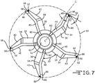
- Relief angle ⁇ illustrated in FIG. 7 , is measured between the intersection of the tip of relieved side edge surface 66 and a tangential plane. More precisely, relief angle ⁇ is measured between a tangent line to the point formed by the edge 66 of the inner surface of planar portion 56 and an imaginary annular line 64 formed by the cutting action of the reamer blade 34.
- Rake angle ⁇ is measured between perpendicular line C-C and the tangent line formed between the intersection of the point formed by the edge 66 of the inner surface of the planar portion 56 and the bone cutting surface 48.
- the bone cutting surface 48 and side edge 66 determines the diameter of the cavity bore 64.
- relief angle ⁇ ranges from about 1° to about 25°. More preferably, relief angle ⁇ ranges from about 5° to about 15°. It is important that the relief angle ⁇ is not zero or negative.
- a negative relief angle ⁇ is an angle in which the flat portion 56 exceeds past side edge 66 of the bone cutting surface 48. In other words, a negative relief angle ⁇ is a reamer blade 34 with the flat portion 56 that extends past the reamed bore diameter 64.
- a negative relief angle ⁇ is not desired because it creates a cavity bore 64 with a lobed inside finish. It is desirable to have a positive relief angle ⁇ that results in a reamed bore with a smooth internal surface.
- Rake angle ⁇ is a measure in which the blade cutting portion 40 deviates from the plane of the blade attachment portion 38. As shown in FIG. 7 , rake angle ⁇ is specifically defined as the angle between the intersection of the distal end of the bone cutting surface 48 and perpendicular axis C-C which extends from the cylindrical body 10. It is preferred that rake angle ⁇ ranges from about 5° to about 25°. It is more preferred that rake angle ⁇ range from about 12° to about 15°.
- Rake angle ⁇ is a measure of the aggressiveness of the cut. A larger rake angle ⁇ increases the aggressiveness of the cut whereas a smaller rake angle ⁇ angle produces a less aggressive cut.
- FIG. 7 illustrates the reamer head assembly 100 from the perspective view point of the distal end 14, looking down its longitudinal axis.
- reamer blades 34 are attached to the cylindrical body 10. Each reamer blade 34 is positioned such that they are oriented in the same direction. Each blade 34 is positioned into each slot 20 with the forward cutting surface 46 and the bone cutting surface 48 facing towards the distal end 14. The rearward relief surface 50 is positioned facing the proximal end 16. In addition, it is preferred that each reamer blade is bent about transition line 54 in the same direction with about the same degree of angle 62.
- the reamer 300 FIG. 10
- the reamer 300 may be constructed with one or more reamer blades 34 with dissimilar bend orientations that may not necessarily have the same degree of angle 62.
- FIG. 8 illustrates a fully assembled reamer head assembly 100 of the present invention.
- each reamer blade 34 is positioned in their respective slot 20.
- the blade attachment portion 38 is positioned within the slot 20 such that the cutting potion 40 is bent about transition line 54 in a clockwise position.
- the reamer blades 34 could also be positioned with the cutting potion 40 bent in a counterclockwise orientation.
- each reamer blade 34 is positioned into a slot 20 such that ridge 54 is bent with a similar angle 62. This preferred orientation creates a desirable helical rotation as the reamer blade 34 penetrates through the intramedullary space.
- each reamer blade 34 is positioned with its forward cutting surface 46 facing toward the distal end 14 of the reamer blade assembly 100.
- each reamer insert blade 34 is positioned from adjacent insert reamer blades 34 by a separation distance 57.
- This separation distance 57 is dependent on the number of insert blades 34 that are attached to the cylindrical body 10. The more blades 34 that are attached to the body 10, the smaller the separation distance 57. Given a typical configuration of five insert reamer blades 34, the separation distance ranges from about 0.3 mm to about 15.0 mm depending on the diameter of the cylindrical body 10.
- the separation distance 57 enables the surgeon to "jump" reamer sizes.
- a reamer size is “jumped”
- the next incremental reamer diameter size is bypassed for a reamer with an even larger diameter.
- reamers of incremental sizes on the order of about 0.5 mm are typically inserted to enlarge the intramedullary space.
- the surgeon can reduce the number of reaming iterations which reduces procedural time and minimizes patient trauma.
- the surgeon can bypass incremental reamer diameters of about 1.0 mm or more.
- the separation distance 57 provides an opening or separation area between reamer blades 34 within which intramedullary debris can freely flow. Designing the present invention with an optimized separation distance 57 reduces the interference resistance and back pressure allowing debris to easily flow over the cylindrical body 10 between the insert reamer blades 34.
- the reamer 300 of the present invention has a separation area that is bounded by the outer surface 18 of the cylindrical body 10 and opposing reamer insert blades 34.
- the insert reamer blades 34 allow for a maximized separation area between adjacent blades 34 that is not obstructed by a portion of the reamer cutting head body of prior designs.
- notch 52 breaks up debris as it passes over the cylindrical body 10, further improving reamer efficiency.
- the cavity cross sectional area is the cross sectional area of the cavity formed by reamer 300 and the reamer cross sectional area is the combined cross-sectional areas of the cylindrical body 10 and blades 34.
- the number of insert blades is the number of insert reamer blades 34 that are attached to the cylindrical body 10. Therefore, by optimally spacing the insert reamer blades 34 around the body 10, an increased amount of intramedullary debris can be removed efficiently. Such improved efficient debris removal improves the efficiency of the reamer tool which results in minimized procedural times and less trauma to the patient.
- FIG. 9 illustrates an additional view of the distal end 14 of the reamer blade assembly 100.
- each reamer blade 34 is positioned into a slot 20.
- the example shown in FIG. 9 illustrates a preferred embodiment of the compound angles 30, 32 of the present invention.
- the blade attachment portion edge 60 is at a preferred angle of about 10° in end slot 32 and the attachment portion edge 36 is at a preferred angle of about 20°.
- the compound angles 30, 32 of the slot 20 help distribute the load into the cylindrical body 10 while allowing the diameter of the cylindrical body 10 to be minimized. This allows the reamer blades 34 to present a desirable helical flute pattern using simple angles for assembly.
- the attachment portion edge 60 and forward cutting edge 46 is shown extending past the distal end 14. Having the reamer 300 with a portion of blade 34 extending past the distal end 14, as shown in FIGS. 8-11 , provides the reamer 300 with front cut capability.
- the forward blade design advances the blade 34 attack angle which enhances the ability of the reamer 300 to jump reamer sizes.
- the attachment portion edge 60 is flush with the distal end 14 of the reamer blade assembly 100.
- reamer 300 can also be designed with a portion of the distal end 14 of the cylindrical body 10 extending past the distal end of the insert reamer blades 34. Such an alternate design with an extended cylindrical distal portion 14 provides for an insertion guide into the intramedullary space.
- FIG. 10 illustrates a preferred embodiment of the reamer shaft 200 of the present invention.
- the reamer shaft 200 is comprised of a coupling portion 212 that is in fluid communication with a tube 210.
- the coupling portion 212 is comprised of a male dovetail end 214 and flat surface 216.
- the male dovetail end 214 is designed to mate with the corresponding female radius 24 and flats 26 located at the proximal end 16 of the cylindrical body 10.
- the male dovetail end 214 slides into the female radius 24. It is preferred that the cylindrical body passageway 12 aligns with the shaft passageway 218 when connecting the reamer head assembly 100 to the shaft 200. It is preferred that the shaft tube 210 is made from a pultruded thermoset polymeric material that can withstand at least 5 N-M of torque. Pultrusion as defined herein is the process by which elongated shapes of polymer are produced. The pultrusion process involves pulling a liquid mixture of polymeric materials and associated resins and chemicals through a die in a continuous manner. Once the reamer shaft 200 is attached, the reamer 300 can be manipulated by hand or alternatively be powered by a motor.
- a motor (not shown) can be connected to the reamer assembly 100 to power rotation of the blades 34.
- a motorized shaft (not shown) can be inserted through the shaft passageway 218 and connected to the reamer head assembly 100.
- a motor (not shown) can be connected to the shaft 200 to provide blade 34 rotation.
- each reamer blade 34 is slid into place in a slot 20 of the cylindrical body 10.
- a heat source emanating from a radio frequency energy source, is applied to the assembly 100 to heat up the blades 34.
- the application of the radio frequency energy to the blades 34 causes the material of the cylindrical body 10 to melt.
- the material of the cylindrical body 10 flows onto the surface 42 of the blade attachment portion 38 and through the engagement openings 44. This creates a fluid connection integrating the reamer blades 34 with the cylindrical body 10. Once the material of the cylindrical body 10 solidifies, the reamer blades 34 are securely locked into place.
- a radio frequency induction power supply (not shown) with a work head and coil operating at a frequency range of about 100 to about 450 Khz is used to inductively weld the insert blades 34 to the cylindrical body 10.
- the preferred welding time of the inductive bonding process is about 1 to about 10 seconds.
- the application of this electrical energy to the reamer blades 34 elevates the blade 34 temperature to effectively melt the surrounding material of the cylindrical body 10. These elevated temperatures preferably range from about 100° C to about 500°C.
- a heat source such as an electromagnetic current, flame or heater could also be targeted to the reamer blades 34 to elevate their temperature.
- reamer blades 34 could also be attached to the cylindrical body 10 through other bonding means.
- These alternately preferred bonding means include, but are not limited to, the use of adhesives, insert molding, over-molding, press fitting, and ultrasonic bonding.
- the induction process provides a cost effective means of constructing the disposable intramedullary reamer 300 ( FIGS. 10 and 11 ) of the present invention.
- the present invention provides for a reamer 300 and fabrication process which eliminates costly traditional machining processes.
- the assembly fabrication process of the present invention allows for reamer designs that could not otherwise be fabricated by traditional methods.
- the present invention enables the use of compound angles 30, 32 in the cylindrical body 10 which bends the reamer blade 34 in an angle that provides improved cutting efficiency. Such an angle would be difficult to fabricate using traditional reamer manufacturing methods.
- the present invention provides for an optimal blade separation distance 57 and associated blade separation area which maximizes debris flow and enhances cutting efficiency.
- the reamer head assembly 100 may be constructed with a hollow shaft tube 210 that does not comprise a coupling portion 212. Such a tube 210 can be inserted directly into the proximal end 16 of the reamer head assembly 100 such that a snug interference fit is created. As illustrated in an alternate embodiment in FIG. 11 , the distal end 220 of reamer shaft tube 210 is inserted into the reamer head assembly inlet 70 located at the assembly proximal end 16. A snug interference fit is created when the reamer shaft tube 210 is inserted into inlet 70.
- the reamer shaft tube 210 can be joined to the reamer head assembly 100 through other means such as, but not limited to, over-molding, adhesive bonding, press fitting, and ultrasonic bonding.
- the reamer head assembly 100 can also be fabricated with an integrated reamer shaft 200 in a one piece construction.
- the proximal end 16 of the cylindrical body 10 is extended such that the shaft 200 is in fluid connection with the reamer head assembly 100.
- the integrated reamer shaft 200 can be solid or preferably fabricated with a central passageway 218.
- the shaft 200 is made from a thermoplastic polymer material having the characteristics which allow it to withstand at least 5 N-M of torque.
- the shaft 200 could also be made from a thermoset polymer material.
- the reamer 300 of the present invention provides for a low cost flexible single use intramedullary cutting tool.
- the present invention does not require additional grinding or re-sharpening procedures which ensures optimal sharpness and sterilization.
- the features of the present invention provide for an efficient intramedullary cutting tool with an optimized cutting design that enhances reaming efficiency and effectiveness.
Description
- The present invention relates to the art of orthopedic reamers, and more particularly, to a disposable flexible reamer used for intramedullary reaming.
- Reamers are tools used in orthopedic procedures to cut bone and associated tissue matter. Specifically, flexible reamers of the present invention are designed to cut and bore into the intramedullary space or inner canal of a long bone such as a femur, tibia or humerus. Typically, the intramedullary space of a long bone is reamed to clean and create a space for an implant. As such, these reamers are required to be sterile and sharp. Using a dull reamer generates heat that typically leads to tissue necrosis and results in undesireable patient outcomes. A non-sterile reamer blade typically results in an infected and damaged intrameduallary space that may lead to other problems for the patient.
-
US 2005/096685 A1 discloses a surgical cutting tool in which at least one slot is formed through the wall of a tubular housing and receives a blade. An actuator is disposed in the bore and engages the blade so that axial movement of the actuator in the bore causes radial movement of the blade relative to the slot to change the amount of tissue to be removed. -
DE 25 42 056 A1 describes a cutting tool for cutting bone. A rotary bone drilling instrument comprises an outer rotatable shank that is formed over an inner rotatable guiding probe. The distal end of the guiding probe has a milling head comprising a spiraled cutting surface. The distal end of the outer shank has a threading cutter comprising a spiraled cutting surface extending from the outside wall surface of the shank. -
DE 10 2005 017 285 A1 discloses an implant bed drill comprising a major cutting edge, a minor cutting edge and a "cutting edge-interrupting" groove. The minor and major cutting edges form a drill bit with a spiraled and tapered cutting surface. -
US 1.957,348 discloses a reamer having a reamer body provided with an annular series of longitudinally extending slots for the reception of blades which are locked in the respective slots by eccentric binding screws. - Reamers are often used in trauma procedures. In one such procedure, a prosthetic implant is inserted into the intramedullary space to help mend a fractured bone. In the procedure, a flexible reamer is first inserted into the intramedullary space of the fractured bone. Using the flexible reamer, a cavity space is then formed for insertion of the implant into the fractured bone.
- Prior to the reaming process, a guide wire is typically inserted into the intramedullary space. The reamer is then passed over the guide wire and inserted into the intrameduallary space for enlarging. The intramedullary space is enlarged incrementally with a series of reamers. A separate interchangeable reamer is required for each step. This requires that each reamer be extracted from the intramedullary space and slid off the guide wire. The next incremental reamer is then passed over the guide wire and advanced into the intramedullary space. This procedure could involve as many as 10 to 15 interchanges.
- Currently, orthopedic reamers are typically fabricated as modular units that are sold in a set of an array of diameters. These reamer tool sets are manufactured with reamer cutting heads providing bore sizes ranging from about 6 mm to about 28 mm in 0.5 mm increments sometimes totaling over 25 sizes. Since it is desirable to achieve a close prosthetic fit, a wide array of reaming tools of variying sizes are required to be at hand to provide the most precise cut and optimum bore diameter.
- Reamers have historically comprised two components, a one-piece reamer cutting head and a reamer shaft that connects to the reamer head assembly. The one-piece reamer cutting head is machined from a single block of metal into a hollow cylinder incorporated with a series of protruding blades that emerge from the outer surface of the cylinder.
- Currently, reamer cutting heads are typically manufactured from a single piece of biocompatible metal. Traditional reamer cutting heads are fabricated using intricate precision machining techniques that create the central cylinder and the series of protruding reamer blades. This manufacturing process is time consuming and is not cost effective.
- Because of their high cost, traditional cutter heads are typically reused multiple times. Over time, as these reamer heads are used and reused, the cutting blades become dull. Therefore the reamer cutting blades are required to be resharpened and sterilized before each reuse. However, this resharpening and sterilization process adds additional cost and increases the possibility of infection. There is a high likelihood that the sterilization process may not remove all possible infection agents such as bacteria, machining lubricants, and the like.
- Often times reamers are used for surgical procedures for which they are not intended. In many cases, the nearest available tool is often used to perform the procedure whether or not it is designed or intended for such use. For example, a set of reamer heads dedicated for intramedullary space reaming, may be used for a cemented hip revision. In this procedure, the reamer cutting head is used to cut away old cement instead of bone. Hip replacement cement tends to be more abrasive than bone, which, therefore increases the wear and stress on the cutting surface. Using these reamer cutting tools to cut into hip replacement cement, typically results in excessive wear of the reamer cutting blade surface which hastens blade degredation. As a result, the tool becomes an ineffective reaming tool. The sharpness of the cutting blade is diminished and the structural soundness of the cutting blade is weakend.
- Unfortunately there is no simple way to evaluate cutting efficiency after these reamer tools have been used and reused, especially after use in procedures for which they are not intended. Many times it isn't until the surgeon uses the reamer again that they become aware that the reamer is cutting incorrectly. In many cases an ineffective, dull, or contaminated reamer tool is not detected until well into the reaming procedure or even after the procedure is complete. Good surgical outcomes are largely dependent on the use of a sharp, sterile reamer that is in optimal condition. Poor surgical outcomes such as a damaged intramedullary space, can occur as a result of using dull or contaminated reamers.
- The geometry of the reamer cutting blade is a major contributor to the sharpness and cutting efficiency of the tool. It is well known in the art that cutting tools with helical flutes are more efficient at cutting bone than straight flutes. Typically helical flutes are manufactured using a grinding process to form them from a solid metal core. Due to the high cost of the process, these tools are typically reused multiple times.
- Examples of helical ground flutes are shown in
U.S. patent 6,258,093 to Edwards which discusses the importance of flute shape, helix angle and grooves on cutting efficiency. Edwards mentions the use of a premolded blank and points out that the flute depth is also an important aspect for debris removal which in turn relates to efficiency. - However, due to their intricate design of grooves and teeth, the embodiments disclosed by Edwards are prone to the same resharpening and sterilization problems that have been previously discussed.
- Furthermore, the reamer blade assembly of the present invention has a feature that allows for increased intramedullary debris removal and reaming efficiencies. This feature, which will be discussed in more detail, is based on an optimal shape and positioning of the insert reamer blades about the cylindrical body of the assembly. This feature is not present nor taught by Edwards or disclosed in the prior art.
- Reamers have also been made of coiled wire. These prior reamer designs are also prone to cleanliness and structural integrity issues. Often times debris becomes entrapped in the springs which are problematic to clean. In addition, these earlier coiled wire reamers often become unwound when driven in the reverse direction.
- Accordingly, the present invention provides a cost effective single use flexible intramedullary reamer with a novel blade and assembly head design that improves cutting efficiency. The enhanced reaming efficiencies of the present invention decrease procedural times and minimize patient trauma. The intramedullary reamer of the present invention ensures sharpness and cleanliness that promotes optimal patient outcomes.
- The invention relates to a disposable reamer head assembly according to claim 1, a disposable intramedullary reamer according to claim 9 comprising the reamer head of the invention and a method of manufacturing a disposable reamer head assembly according to
claim 10. - The present disclosure provides a disposable reamer comprising a reamer head assembly and a reamer shaft. The reamer head assembly further comprises a cylindrical body and a series of insert reamer blades which are attached to the outside surface of the cylindrical body. The cylindrical body is universal and can be preferably manufactured with a hollow core to allow clearance for the passage of a guide wire and/or intramedullary debris. Formed into the cylindrical body are slots which extend along the outer surface of the body. These slots are adapted to receive a series of insert reamer blades. Each blade is arranged with a preferred separation distance and helical orientation along the outer surface of the body.
- Each insert reamer blade is comprised of a reamer blade attachment portion and a reamer blade cutting portion. The reamer blade attachment portion has a bottom edge and engagement openings for mating with the slot. The cutting portion of the blade further comprises a forward blade surface, a bone cutting surface, and a rearward relief surface. A transition line extending along a longitudinal axis of the blade body partitions the blade attachment portion from the reamer blade cutting portion. Each blade is bent about this transition line. When fully assembled, the angled reamer blades create a helical cutting path as they are rotated.
- Each blade is placed in the cylindrical body such that the bottom edge of the blade attachment portion resides in the slot with the blade cutting portion protruding from the outer surface of the body. Each blade is further oriented with its forward blade surface positioned towards the distal end of the cylindrical body. In addition, each reamer blade is positioned about the outer surface of the cylindrical body at an optimum separation distance from adjacent reamer blades. This optimal separation distance allows for unobstructed flow of intramedullary debris over the cylindrical body which results in increased blade stability and efficiency.
- When correctly positioned in the slot, the forward surface of the blade initially begins to bore into the intramedullary space. The positively sloping surface of the forward blade surface pushes the intramedullary material to the bone cutting surface, which in turn cuts through the intramedullary tissue matter. The bone cutting surface is positioned proximal of the forward blade surface. The negatively sloped rearward relief surface serves to stabilize the blade as it bores deeper into the intramedullary space. The sloping surface of the rearward relief surface also enables the reamer to cut through tissue when traversing in the reverse direction.
- During the manufacturing process, each blade is engaged in their respective cylinder slot. Once positioned in the slots, the blades are bonded to the cylindrical body via an induction heating process. During this induction heating process, the reamer head assembly is subjected to a heat source which melts the surrounding material of the cylindrical body. The melted material flows into the slot, covering the surface of the blade attachment portion. The flowing molten material then penetrates through the blade engagement openings, creating a fluid connection between the cylindrical body and the insert reamer blade, thereby bonding each blade with the body. This low cost production process avoids the need for expensive grinding operations and can use simple stamping or chemical etching to form the insert blades.
- Each slot is designed with a compound angle which further positions the reamer blade in a preferred helical orientation. The compound slot angle helps impart a twisting motion from the forward blade cutting surface to the rearward relief blade surface when the blade is rotated through the intramedullary space. Therefore, the combination of the compound slot angle with the reamer blade bend creates an efficient and effective reamer cutting tool.
- In addition to the reamer head assembly, a reamer shaft can also be provided. This reamer shaft can be provided with a removable interference fit, a locking junction, or can be designed as an integral portion of the reamer.
-
-
FIG. 1 is a perspective view of the cylindrical body of the present invention. -
FIG. 2 is an end view of the distal end portion of the cylindrical body of the present invention. -
FIGS. 3 and 4 are side views taken from the side of the cylindrical body of the present invention. -
FIGS. 5 and 5A are perspective and plane illustrations, respectively, of preferred embodiments of the insert reamer blade of the present invention. -
FIGS. 6 and 6A are illustrations of the insert reamer blade of the present invention showing examples of preferred bend angles. -
FIG. 7 is an illustration of the reamer blade assembly of the present invention taken from the distal end portion. -
FIGS. 8 and9 are respective dissembled and assembled perspective views of the reamer blade assembly of the present invention. -
FIG. 10 illustrates a perspective view of a preferred embodiment of the reamer shaft of the present invention. -
FIG. 11 illustrates a perspective view of an alternate embodiment of the reamer shaft of the present invention. - Now turning to the figures, illustrated in
FIGS. 1-4 is acylindrical body 10. Thiscylindrical body 10 forms the central foundation to which eachreamer blade 34 of the present invention is attached. Thecylindrical body 10 has a length, a thickness and an outer diameter. Thecylindrical body 10 can be made of a solid construction. However, in a preferred embodiment, thebody 10 can be constructed with acentral passageway 12 that extends longitudinally through the thickness and along the length of thebody 10 from aproximal end portion 16 to thedistal end 14. Thiscentral passageway 12 allows for the insertion of a guide wire (not shown) and allows for the passage of debris that is removed from the intramedullary space. It is contemplated that a vacuum tube could be inserted into thepassageway 12 to remove debris. It is preferred that the length of thecylindrical body 10 ranges from about 1.0 mm to about 20.0 mm and that the outer diameter ranges from about 1.0 mm to about 15.0 mm. It is also preferred that the diameter of thepassageway 12 ranges from about 0.5 mm to about 5.0 mm. Thecylindrical body 10 is made of a biocompatible material, preferably a moldable biocompatible polymeric material. Preferred polymeric materials include, but are not limited to, polyetheretherketone (PEEK), polyarylamide (PARA) and acrylonitrile butadiene styrene (ABS). - Formed into the
outer surface 18 of thecylindrical body 10 are a series ofslots 20. In a preferred embodiment, eachslot 20 has aslot width 15 and aslot depth 17 sized to receive areamer blade insert 34. Eachslot 20 has aslot length 19 that extends from aproximal end portion 16 of thecylindrical body 10 to a portion of thedistal end 14. It is also preferred that eachslot 20 is formed partially cut into thecylindrical body 10 such that theslot depth 17 does not penetrate into thecentral passageway 12. - In a preferred embodiment,
slot 20 is fabricated with a compound angle. The compound angle comprises afirst slot angle 30 and asecond slot angle 32. As shown inFIG. 3 , thefirst slot angle 30 is measured with respect to longitudinal axis A-A. Thefirst slot angle 30 is the angle at which thelength 19 ofslot 20 deviates from the longitudinal axis A-A as it extends along theouter surface 18 of thecylindrical body 10. It is preferred that thefirst slot angle 30 deviates from longitudinal axis A-A by about 3° to about 30°. - The
second slot angle 32 is the angle at whichslot 20 is cut into the surface of thecylindrical body 10. As shown inFIG. 2 , thesecond slot angle 32 is measured with respect to perpendicular axis C-C which extends from theouter surface 18 of thecylindrical body 10 perpendicular to the longitudinal axis A-A. It is preferred that thesecond slot angle 32 deviates from the perpendicular axis by about 5° to about 45°. - The compound angles 30, 32 of
cylindrical body 10 of the present invention are designed such that when eachreamer blade 34 is positioned in aslot 20, the blade cutting portion 40 (FIG. 9 ) follows a helical path as it penetrates into the intramedullary space. - Alternatively,
cylindrical body 10 can be fabricated with aslot 20 that does not have a compound angle. In this alternatively preferred embodiment, thecylindrical body 10 is constructed with aslot 20 with afirst slot angle 30.Slot angle 30, similarly to the previous embodiment, has aslot length 19 that extends from aproximal end portion 16 to thedistal end 14. - In a preferred embodiment, shown in
FIG. 1 , theproximal end 16 of thecylindrical body 10 has adovetail interface 22 that comprises afemale radius 24 andflats 26. Thisdovetail interface 22 is designed to receive and lock into place a corresponding dovetailmale end 214 of a reamer shaft 200 (FIG. 10 ). Theflats 26 have a preferredgroove 28 that provides for a quick connect mechanism described in White patent6,918,913 - The corresponding distal
male end 214 of the reamer shaft 200 (FIG. 10 ) slides into thedovetail interface 22 located at theproximal end portion 16 of thecylindrical body 10. The interface of these two features provides a quick means of locking and releasing thereamer head assembly 100 to thereamer shaft 200. However, it is contemplated that theproximal end 16 of thecylindrical body 10 could be constructed as a continuation of the hollowcylindrical body 10. Thereamer shaft 200 could then be inserted into the hollowproximal end 16 of thebody 10. -
FIG. 5 illustrates a preferred embodiment of aninsert reamer blade 34 of the present invention.Blades 34 are preferably constructed from biocompatible metals such as stainless steel. Other preferred metals include, but are not limited to, 316 stainless steel, MP35N, titanium, and combinations thereof. - In the preferred embodiment illustrated in
FIG. 5 , thereamer blade 34 has a continuous blade surface comprising anattachment portion 38 and ablade cutting portion 40. The twoportions transition line 54 that extends along longitudinal axis B-B.Transition line 54 serves as a boundary that partitions theattachment portion 38 from theblade cutting portion 40. In addition, as will be explained in more detail,transition line 54 also serves as the line about whichblade 34 is bent. - The
attachment portion 38 further comprises a planarrectangular surface 42 with abottom edge 36 with forward facingside edge 60. Thebottom edge 36 extends parallel to the blade longitudinal axis B-B and serves as the surface that interfaces with the bottom ofslot 20. Thebottom edge 36 has a thickness that preferably ranges from about 0.5 mm to about 10 mm. - It is preferred that
planar surface 42 comprises a roughened finish and a series ofengagement openings 44 that aid in the induction bonding process. During the induction bonding process, molten polymeric material of thebody 10, flows through theengagement openings 44, creating a fluid connection between thecylindrical body 10 andreamer blade 34. Once the molten polymeric material hardens, thereamer blade 34 becomes securely anchored to thebody 10. - The
blade cutting portion 40 comprises aforward cutting surface 46, abone cutting surface 48 and arearward relief surface 50. As illustrated inFIG. 5 , in a preferred embodiment, the cuttingportion 40 extends seamlessly from theforward blade surface 46, located at a distal end of the reamer blade to therearward relief surface 50, located at a proximal end of the reamer. Thebone cutting surface 48 is disposed between theforward cutting surface 46 and therearward relief surface 50. - The
forward cutting surface 46, thebone cutting surface 48 and therearward relief surface 50 are provided along the outer perimeter of theblade cutting portion 40 of thereamer blade 34. In the preferred embodiment illustrated inFIG. 5 , the forward cuttingsurface 46 and the rearward cuttingsurface 50 have rounded or convex surfaces. - The
bone cutting surface 48 fluidly transitions from theforward cutting surface 46 to therearward relief surface 50. - It is preferred that the
bone cutting surface 48 forms an angle that ranges from about 40° to about 50°, most preferably about 45°, with respect to the blade longitudinal axis B-B. It is also preferred that theforward cutting surface 46 andbone cutting surface 48 have a sharp edge with a blade thickness 35 (FIGS. 8 and9 ) that ranges from about 0.1 mm to about 5.0 mm. - In an alternate embodiment shown in
FIG. 5A , thereamer blade 34A may be fabricated in a shape that is similar to that of a triangle. Unlike the cuttingportion 40 shown inFIG. 5 , the alternate embodiment shown inFIG. 5A , has aforward cutting surface 46A and arearward relief surface 50A that are not rounded. More specifically, the alternate embodiment of the cutting portion 40A shown inFIG. 5A is comprised of aforward cutting surface 46A and arearward relief surface 50A that have angled straight edges. The angles forming the forward cutting surface 46A and therearward relief surface 50 are measured with respect tobottom edge 36A. It is preferred that the forward cutting surface 46A is angled from about 10° to about 65°with respect tobottom edge 36A. It is also preferred that therearward relief surface 50 is angled from about 100° to about 170°with respect tobottom edge 36A. - Referring back to
FIG. 5 , theblade cutting portion 40 is designed to cut a round cavity in the intramedullary space of a bone. To increase the cutting efficiency, a groove or notch 52 is positioned through a portion of the edge of theblade cutting portion 40. At least onenotch 52 is provided proximal of thebone cutting surface 48. Preferably thenotch 52 is cut through aflat portion 56 of the outer edge of theblade cutting portion 40. Thisplanar surface 56 extends between thebone cutting surface 48 and the rearward relief surface 50 (relief surface 50A inFIG. 5A ).Planar surface 56 acts as ablade 34 stabilizer, minimizing lateral motion of thereamer blade 34 as it penetrates through the intramedullary space. Alternatively thenotch 52 may be cut through the edge of a portion of therearward cutting surface 50. - Preferably, the forward cutting
surface 46 is configured to initiate an opening into the intramedullary space or bone canal. Once the opening in the intramedullary space has been initiated, thebone cutting surface 48 begins to cut the bone and tissue material. Thebone cutting surface 48 is fabricated to efficiently cut through the material of the intramedullary space so as to create a bored hole with a smooth internal cavity surface. Therearward relief surface 50 acts to stabilize thereamer blade 34. Therearward relief surface 50 of thereamer blade 34 extends from the flat 56 orbone cutting surface 48 to the proximal end of theblade 34. Therearward relief surface 50 stabilizes the rotation of thereamer blade 34 as it bores through the intramedullary space. A stabilizedreamer head assembly 100 contributes to a reamed cavity with a smooth internal surface. Therearward relief surface 50 can be fabricated with a rounded surface as shown inFIG. 5 or alternatively can be fabricated with a straight angled surface as shown inFIG. 5A . - In a preferred embodiment, the
reamer blade 34 is bent alongtransition line 54 such that the plane of the cuttingportion 40 deviates from the plane of theattachment portion 38. Eachreamer blade 34 is bent along thetransition line 54 such that theblade cutting portion 40 and theblade attachment portion 38 are not coplanar.FIGS. 6 and 6A illustrate examples of preferred embodiments of this bend alongtransition line 54. In a preferred embodiment,transition line 54 extends longitudinally across the length of thereamer blade 34. Thetransition line 54 is further positioned such that the width of the cuttingportion 40 is greater than the width of theblade attachment portion 38. The width of theblade cutting portion 40 is defined as the distance between thetransition line 54 and the outer edge of theflat portion 56. The width of theblade attachment portion 38 is defined as the distance between thetransition line 54 and the bottom edge of theattachment portion 36. Alternatively, thetransition line 54 may be positioned such that the width of the cuttingportion 40 is less than the width of theblade attachment portion 38. It is preferred that thereamer blade 34 is bent alongtransition line 54 such that when each of theblades 34 is assembled in thecylindrical body 10, they are in the same orientation, such as theblade 34 orientation shown inFIGS. 8 and9 . This orientation provides for a uniform helical cutting motion as the reamer head assembly 100 (FIG. 9 ) rotably advances through the intramedullary space. -
FIG. 6 illustrates a preferred embodiment in which theblade cutting portion 40 has a radius of curvature. This radius of curvature is defined byradius 58 which can range from about 3 mm to about 15 mm. In addition to the radius of curvature, cuttingportion 40 is further bent alongtransition line 54 byangle 62.Angle 62 as illustrated inFIGS. 6 and 6B is defined as the sweep between the tangent plane that intersectsedge 66 andblade surface 48, and the side planar surface ofblade attachment portion 38. It is preferred thatangle 62 ranges from about 85° to about 175°. More preferably,angle 62 ranges from about 145° to about 165° and most preferably from about 150° to about 160°. - In an alternately preferred embodiment, as illustrated in
FIG. 6A ,reamer blade 34 has a cuttingportion 40 with an angled plane. Unlike the previous embodiment shown inFIG. 6 , the plane of the cuttingportion 40 is not curved. The cuttingportion 40 of the embodiment shown inFIG. 6A , is fabricated with a straight edge that is bent alongtransition line 54. Thisbend angle 62 is measured between the surface of theblade cutting portion 40 andsurface 42 of theblade attachment portion 38. It is preferred thatangle 62 range from about 85° to about 175°. More preferablyangle 62 ranges from about 145° to about 165° and most preferably from about 150° to about 160°. - As shown in
FIGS. 6,6A and7 , the quality of the reamed intramedullary space is largely dependent uponadditional reamer blade 34 parameters. These additional parameters include a cutting edge angle α, a relief angle β, a rake angle γ, and the relationship between these parameters. Areamer blade 34 with an optimized cutting edge angle α, relief angle β, and rake angle γ produce a reamed cavity with a desirable smooth bore surface. If thereamer blades 34 are not designed with these optimized parameters, a reamed cavity with an undesirable lobed surface is created. A lobed cavity surface is one in which the surface has lumps or has a scalloped surface. - Cutting edge angle α, illustrated in
FIGS. 6 and 6A , is the clearance between theside edge 66 of thebone cutting surface 48 andplanar portion 56. More precisely, angle α is measured between the planar face ofedge 66 and a tangent line to the point formed byedge 66 of the inner surface ofplanar portion 56. Preferably cutting edge angle α ranges from about 1° to about 50°. Relief angle β, illustrated inFIG. 7 , is measured between the intersection of the tip of relievedside edge surface 66 and a tangential plane. More precisely, relief angle β is measured between a tangent line to the point formed by theedge 66 of the inner surface ofplanar portion 56 and an imaginaryannular line 64 formed by the cutting action of thereamer blade 34. Rake angle γ, also illustrated inFIG. 7 , is measured between perpendicular line C-C and the tangent line formed between the intersection of the point formed by theedge 66 of the inner surface of theplanar portion 56 and thebone cutting surface 48. Thebone cutting surface 48 andside edge 66 determines the diameter of the cavity bore 64. - In a preferred embodiment shown in
FIG. 7 , relief angle β ranges from about 1° to about 25°. More preferably, relief angle β ranges from about 5° to about 15°. It is important that the relief angle β is not zero or negative. A negative relief angle β is an angle in which theflat portion 56 exceedspast side edge 66 of thebone cutting surface 48. In other words, a negative relief angle β is areamer blade 34 with theflat portion 56 that extends past the reamed borediameter 64. A negative relief angle β is not desired because it creates a cavity bore 64 with a lobed inside finish. It is desirable to have a positive relief angle β that results in a reamed bore with a smooth internal surface. - In addition to relief angle β, rake angle γ is also an important parameter of the present invention. Rake angle γ is a measure in which the
blade cutting portion 40 deviates from the plane of theblade attachment portion 38. As shown inFIG. 7 , rake angle γ is specifically defined as the angle between the intersection of the distal end of thebone cutting surface 48 and perpendicular axis C-C which extends from thecylindrical body 10. It is preferred that rake angle γ ranges from about 5° to about 25°. It is more preferred that rake angle γ range from about 12° to about 15°. Rake angle γ is a measure of the aggressiveness of the cut. A larger rake angle γ increases the aggressiveness of the cut whereas a smaller rake angle γ angle produces a less aggressive cut. -
FIG. 7 illustrates thereamer head assembly 100 from the perspective view point of thedistal end 14, looking down its longitudinal axis. As the illustration shows,reamer blades 34 are attached to thecylindrical body 10. Eachreamer blade 34 is positioned such that they are oriented in the same direction. Eachblade 34 is positioned into eachslot 20 with theforward cutting surface 46 and thebone cutting surface 48 facing towards thedistal end 14. Therearward relief surface 50 is positioned facing theproximal end 16. In addition, it is preferred that each reamer blade is bent abouttransition line 54 in the same direction with about the same degree ofangle 62. Although it is contemplated that the reamer 300 (FIG. 10 ) may be constructed with one ormore reamer blades 34 with dissimilar bend orientations that may not necessarily have the same degree ofangle 62. -
FIG. 8 illustrates a fully assembledreamer head assembly 100 of the present invention. As shown, eachreamer blade 34 is positioned in theirrespective slot 20. In a preferred embodiment, theblade attachment portion 38 is positioned within theslot 20 such that the cuttingpotion 40 is bent abouttransition line 54 in a clockwise position. Alternatively, thereamer blades 34 could also be positioned with the cuttingpotion 40 bent in a counterclockwise orientation. However oriented, either in a clockwise or counter clockwise orientation, it is preferred that eachreamer blade 34 is positioned into aslot 20 such thatridge 54 is bent with asimilar angle 62. This preferred orientation creates a desirable helical rotation as thereamer blade 34 penetrates through the intramedullary space. Furthermore as illustrated inFIG. 8 , eachreamer blade 34 is positioned with itsforward cutting surface 46 facing toward thedistal end 14 of thereamer blade assembly 100. - In a preferred embodiment shown in
FIG. 8 , eachreamer insert blade 34 is positioned from adjacentinsert reamer blades 34 by aseparation distance 57. Thisseparation distance 57 is dependent on the number ofinsert blades 34 that are attached to thecylindrical body 10. Themore blades 34 that are attached to thebody 10, the smaller theseparation distance 57. Given a typical configuration of fiveinsert reamer blades 34, the separation distance ranges from about 0.3 mm to about 15.0 mm depending on the diameter of thecylindrical body 10. - The
separation distance 57 enables the surgeon to "jump" reamer sizes. When a reamer size is "jumped", the next incremental reamer diameter size is bypassed for a reamer with an even larger diameter. For example, during a reaming procedure, reamers of incremental sizes on the order of about 0.5 mm are typically inserted to enlarge the intramedullary space. By "jumping" reamer sizes, the surgeon can reduce the number of reaming iterations which reduces procedural time and minimizes patient trauma. With thereamer 300 of the present invention, the surgeon can bypass incremental reamer diameters of about 1.0 mm or more. - In addition, the
separation distance 57 provides an opening or separation area betweenreamer blades 34 within which intramedullary debris can freely flow. Designing the present invention with an optimizedseparation distance 57 reduces the interference resistance and back pressure allowing debris to easily flow over thecylindrical body 10 between theinsert reamer blades 34. Unlike previous reamer designs, thereamer 300 of the present invention has a separation area that is bounded by theouter surface 18 of thecylindrical body 10 and opposingreamer insert blades 34. Theinsert reamer blades 34 allow for a maximized separation area betweenadjacent blades 34 that is not obstructed by a portion of the reamer cutting head body of prior designs. Furthermore, notch 52 breaks up debris as it passes over thecylindrical body 10, further improving reamer efficiency. - The optimized separation area is given by the generalized equation:

- Where the cavity cross sectional area is the cross sectional area of the cavity formed by
reamer 300 and the reamer cross sectional area is the combined cross-sectional areas of thecylindrical body 10 andblades 34. The number of insert blades is the number ofinsert reamer blades 34 that are attached to thecylindrical body 10. Therefore, by optimally spacing theinsert reamer blades 34 around thebody 10, an increased amount of intramedullary debris can be removed efficiently. Such improved efficient debris removal improves the efficiency of the reamer tool which results in minimized procedural times and less trauma to the patient. -
FIG. 9 illustrates an additional view of thedistal end 14 of thereamer blade assembly 100. As shown, eachreamer blade 34 is positioned into aslot 20. The example shown inFIG. 9 illustrates a preferred embodiment of the compound angles 30, 32 of the present invention. As shown, the bladeattachment portion edge 60 is at a preferred angle of about 10° inend slot 32 and theattachment portion edge 36 is at a preferred angle of about 20°. The compound angles 30, 32 of theslot 20 help distribute the load into thecylindrical body 10 while allowing the diameter of thecylindrical body 10 to be minimized. This allows thereamer blades 34 to present a desirable helical flute pattern using simple angles for assembly. - In a preferred embodiment shown in
FIG. 9 , theattachment portion edge 60 and forward cuttingedge 46 is shown extending past thedistal end 14. Having thereamer 300 with a portion ofblade 34 extending past thedistal end 14, as shown inFIGS. 8-11 , provides thereamer 300 with front cut capability. The forward blade design advances theblade 34 attack angle which enhances the ability of thereamer 300 to jump reamer sizes. In an alternately preferred embodiment, theattachment portion edge 60 is flush with thedistal end 14 of thereamer blade assembly 100. Alternatively,reamer 300 can also be designed with a portion of thedistal end 14 of thecylindrical body 10 extending past the distal end of theinsert reamer blades 34. Such an alternate design with an extended cylindricaldistal portion 14 provides for an insertion guide into the intramedullary space. -
FIG. 10 illustrates a preferred embodiment of thereamer shaft 200 of the present invention. As shown, thereamer shaft 200 is comprised of acoupling portion 212 that is in fluid communication with atube 210. In a preferred embodiment, thecoupling portion 212 is comprised of amale dovetail end 214 andflat surface 216. Themale dovetail end 214 is designed to mate with the correspondingfemale radius 24 andflats 26 located at theproximal end 16 of thecylindrical body 10. - When connecting the
reamer head assembly 100 to thereamer shaft 200, themale dovetail end 214 slides into thefemale radius 24. It is preferred that thecylindrical body passageway 12 aligns with theshaft passageway 218 when connecting thereamer head assembly 100 to theshaft 200. It is preferred that theshaft tube 210 is made from a pultruded thermoset polymeric material that can withstand at least 5 N-M of torque. Pultrusion as defined herein is the process by which elongated shapes of polymer are produced. The pultrusion process involves pulling a liquid mixture of polymeric materials and associated resins and chemicals through a die in a continuous manner. Once thereamer shaft 200 is attached, thereamer 300 can be manipulated by hand or alternatively be powered by a motor. In an alternately preferred embodiment, a motor (not shown) can be connected to thereamer assembly 100 to power rotation of theblades 34. A motorized shaft (not shown) can be inserted through theshaft passageway 218 and connected to thereamer head assembly 100. Alternatively, a motor (not shown) can be connected to theshaft 200 to provideblade 34 rotation. - As previously mentioned, the present invention is assembled using an induction bonding process. In a preferred method, each
reamer blade 34 is slid into place in aslot 20 of thecylindrical body 10. Once theblades 34 are in position, a heat source, emanating from a radio frequency energy source, is applied to theassembly 100 to heat up theblades 34. The application of the radio frequency energy to theblades 34 causes the material of thecylindrical body 10 to melt. The material of thecylindrical body 10 flows onto thesurface 42 of theblade attachment portion 38 and through theengagement openings 44. This creates a fluid connection integrating thereamer blades 34 with thecylindrical body 10. Once the material of thecylindrical body 10 solidifies, thereamer blades 34 are securely locked into place. - In a preferred embodiment, a radio frequency induction power supply (not shown) with a work head and coil operating at a frequency range of about 100 to about 450 Khz is used to inductively weld the
insert blades 34 to thecylindrical body 10. The preferred welding time of the inductive bonding process is about 1 to about 10 seconds. The application of this electrical energy to thereamer blades 34 elevates theblade 34 temperature to effectively melt the surrounding material of thecylindrical body 10. These elevated temperatures preferably range from about 100° C to about 500°C. Alternately, a heat source such as an electromagnetic current, flame or heater could also be targeted to thereamer blades 34 to elevate their temperature. - Furthermore it is contemplated that the
reamer blades 34 could also be attached to thecylindrical body 10 through other bonding means. These alternately preferred bonding means include, but are not limited to, the use of adhesives, insert molding, over-molding, press fitting, and ultrasonic bonding. - The induction process provides a cost effective means of constructing the disposable intramedullary reamer 300 (
FIGS. 10 and11 ) of the present invention. As previously discussed, the present invention provides for areamer 300 and fabrication process which eliminates costly traditional machining processes. In addition, the assembly fabrication process of the present invention allows for reamer designs that could not otherwise be fabricated by traditional methods. For example, the present invention enables the use of compound angles 30, 32 in thecylindrical body 10 which bends thereamer blade 34 in an angle that provides improved cutting efficiency. Such an angle would be difficult to fabricate using traditional reamer manufacturing methods. In addition, the present invention provides for an optimalblade separation distance 57 and associated blade separation area which maximizes debris flow and enhances cutting efficiency. - Alternatively the
reamer head assembly 100 may be constructed with ahollow shaft tube 210 that does not comprise acoupling portion 212. Such atube 210 can be inserted directly into theproximal end 16 of thereamer head assembly 100 such that a snug interference fit is created. As illustrated in an alternate embodiment inFIG. 11 , thedistal end 220 ofreamer shaft tube 210 is inserted into the reamerhead assembly inlet 70 located at the assemblyproximal end 16. A snug interference fit is created when thereamer shaft tube 210 is inserted intoinlet 70. Alternatively, thereamer shaft tube 210 can be joined to thereamer head assembly 100 through other means such as, but not limited to, over-molding, adhesive bonding, press fitting, and ultrasonic bonding. - Furthermore, the
reamer head assembly 100 can also be fabricated with anintegrated reamer shaft 200 in a one piece construction. In this alternatively preferred embodiment, theproximal end 16 of thecylindrical body 10 is extended such that theshaft 200 is in fluid connection with thereamer head assembly 100. Theintegrated reamer shaft 200 can be solid or preferably fabricated with acentral passageway 218. Preferably, theshaft 200 is made from a thermoplastic polymer material having the characteristics which allow it to withstand at least 5 N-M of torque. Alternatively, theshaft 200 could also be made from a thermoset polymer material. - Thus, it has been shown that the
reamer 300 of the present invention provides for a low cost flexible single use intramedullary cutting tool. The present invention does not require additional grinding or re-sharpening procedures which ensures optimal sharpness and sterilization. The features of the present invention provide for an efficient intramedullary cutting tool with an optimized cutting design that enhances reaming efficiency and effectiveness.
Claims (14)
- A disposable reamer head assembly (100) configured for cutting through an intramedullary space of a long bone, comprising:a) a cylindrical body (10) extending along a longitudinal axis and comprising an outer surface (18), a proximal end portion (16) and a distal end portion (14), a central passageway (12) extending longitudinally through the body thickness and along the body length; and a series of body slots (20) formed partially cut from a position within the outer surface (18) of the cylindrical body (10) into the cylindrical body (10), each of said body slots (20) having a slot length (19) being not parallel with the longitudinal axis and extending from a portion of the cylindrical body proximal end to a portion of the cylindrical body distal end, and having a slot depth (17), the slot depth (17) extending through the outer surface (18) of the cylindrical body (10) such that the slot depth (17) does not penetrate into the central passageway (12) ;b) at least two reamer blades (34), each being continuous and comprising a reamer blade attachment portion (38) and a reamer blade cutting portion (40), partitioned therebetween by a reamer blade transition line (54) that extends along a reamer blade longitudinal axis; andc) wherein each reamer blade (34) is bent at an angle along the transition line (54) such that the reamer blade cutting portion (40) and the reamer blade attachment portion (38) are not coplanar, and wherein each reamer blade (34) is positioned about the cylindrical body (10), spaced apart from adjacent reamer blades (34) by a blade separation distance (57) and a blade separation area therebetween, whereby each reamer blade attachment portion (38) is positioned in the respective body slot (20) and is attached to the distal end portion (14) of the cylindrical body (10) such that the at least two reamer blades (34) are integrated with the cylindrical body (10) therebetween.
- The disposable reamer head assembly (100) of claim 1, wherein the angle between the reamer blade attachment portion (38) and the reamer blade cutting portion (40) is 85 ° to 175 °.
- The disposable reamer head assembly (100) of any of claims 1 or 2, wherein the blade separation distance (57) ranges from 0.3 mm to 15.0 mm, and/or wherein the blade separation area is defined by:

- The disposable reamer head assembly (100) of any of claims 1 to 3, wherein the cylindrical body slot (20) has a first slot angle (30) and a second slot angle (32), the first slot angle (30) comprising the angle of deviation between the slot length and a central cylindrical body longitudinal axis, the second slot angle (32) comprising the angle between the slot depth and a perpendicular axis extending from the central longitudinal axis, preferably wherein the first slot angle (30) is from 5 ° to 30 °and the second slot angle (32) is from 5 °to 45 °.
- The disposable reamer head assembly (100) of any of claims 1 to 4, wherein the cutting surface extends from a forward blade surface (46), located at a distal end portion of the reamer blade (34) to a rearward relief surface (50), located at a proximal end portion of the reamer, with a bone cutting surface (48) disposed therebetween, the bone cutting surface (48) having an angled surface measuring from 40 ° to 50 ° with respect to the reamer blade longitudinal axis.
- The disposable reamer head assembly (100) of any of claims 1 to 5, wherein each reamer blade (34) has a relief angle (β) and a rake angle (γ), preferably wherein the relief angle (β) measures from 1 ° to 25 ° and the rake angle (γ) measures from 5 ° to 25 °.
- The disposable reamer head assembly (100) of any of claims 1 to 6, wherein each reamer blade (34) is composed of a material selected from the group consisting of stainless steel, MP35N, titanium, and combinations thereof, and/or wherein the cylindrical body (10) is composed of a moldable biocompatible polymeric material.
- The disposable reamer head assembly (100) of any of claims 1 to 7, wherein the proximal end portion (16) of the reamer head assembly (100) is connectable to a reamer shaft (200).
- A disposable intramedullary reamer (300) comprising the disposable reamer head assembly (100) according to any one of claims 1 to 8, wherein the proximal end portion (16) is connectable to a reamer shaft (200); and the forward blade cutting surface (46) is positioned toward the cylindrical body distal end portion (14) and the rearward relief blade surface (50) is positioned toward the cylindrical body proximal end portion (16).
- A method of manufacturing a disposable reamer head assembly (100), the method comprising:a) fabricating at least two reamer blades (34) each being continuous and having a blade width and a blade length, comprising a reamer blade attachment portion (38) and a reamer blade cutting portion (40), said portions (38, 40) being partitioned therebetween by a reamer blade transition line (54) parallel to the blade length, the reamer blade cutting portion (40) further comprising a forward blade cutting surface (46) and a rearward relief blade surface (50);b) creating a cylindrical body (10) that extends along a longitudinal axis, the cylindrical body comprising an outer surface (18), a length, a proximal end portion (16), a distal end portion (14) and a central passageway (12) extending longitudinally through the body thickness and along the body length, and a series of slots (20) formed partially cut from a position within the outer surface (18) of the cylindrical body (10) into the cylindrical body (10), each of said body slots (20) having a slot length (19) that is not parallel with longitudinal axis and extends from a portion of the cylindrical body proximal end to a portion of the cylindrical body distal end, and has a slot depth (17), the slot depth (17) extending through the outer surface (18) of the cylindrical body (10) such that the slot depth (17) does not penetrate into the central passageway (12);c) inserting the at least two reamer blades (34) in the respective slots (20) of the cylindrical body distal end portion (14) such that each reamer blade (34) is spaced apart from adjacent blades by a blade separation distance (57), the forward blade cutting surface (46) positioned facing the cylindrical body distal end portion and the rearward relief blade surface facing the cylindrical body proximal end portion; andd) heating the at least two reamer blades (34) such that material of the surrounding cylindrical body (10) melts, thereby integrating the at least two reamer blades (34) with the cylindrical body (10) therebetween.
- The method of claim 10, including providing each reamer blade (34) with a bend angle along the transition line (54) such that the blade cutting portion and the blade attachment portion (38) are not coplanar, preferably also including providing the bend angle between the reamer blade attachment portion (38) and the reamer blade cutting portion (40) with an angle from 85 ° to 175 °.
- The method of claims 10 or 11, including providing the blade separation distance (57) ranging from 0.3 mm to 15.0 mm, and/or including providing the cylindrical body slot (20) with a first slot angle (30) and a second slot angle (32), the first slot angle (30) comprising the angle of deviation between the slot length and a central cylindrical body longitudinal axis, the second slot angle (32) comprising the angle between the slot depth and a perpendicular axis extending from the central longitudinal axis, the first slot angle measuring from 5 ° to 30 ° and the second slot angle measuring 5° to 45°.
- The method of any of claims 10 to 12, including heating the reamer blades (34) from 100 °C to 500 °C.
- The method of any of claims 10 to 13, wherein the at least two reamer blades (34) are composed of a material selected from the group consisting of stainless steel, MP35N, titanium, and combinations thereof, and/or including providing a cylindrical body (10) composed of a moldable biocompatible polymer.
Applications Claiming Priority (1)
| Application Number | Priority Date | Filing Date | Title |
|---|---|---|---|
| US28648709P | 2009-12-15 | 2009-12-15 |
Publications (2)
| Publication Number | Publication Date |
|---|---|
| EP2335617A1 EP2335617A1 (en) | 2011-06-22 |
| EP2335617B1 true EP2335617B1 (en) | 2018-09-12 |
Family
ID=43769165
Family Applications (1)
| Application Number | Title | Priority Date | Filing Date |
|---|---|---|---|
| EP10195161.4A Active EP2335617B1 (en) | 2009-12-15 | 2010-12-15 | Disposable flex reamer |
Country Status (2)
| Country | Link |
|---|---|
| US (1) | US8454608B2 (en) |
| EP (1) | EP2335617B1 (en) |
Cited By (1)
| Publication number | Priority date | Publication date | Assignee | Title |
|---|---|---|---|---|
| EP2967593B1 (en) * | 2013-03-15 | 2023-08-30 | Misonix Incorporated | Ultrasonic surgical drill |
Families Citing this family (17)
| Publication number | Priority date | Publication date | Assignee | Title |
|---|---|---|---|---|
| CH705550A1 (en) * | 2011-09-16 | 2013-03-28 | Chirmat Sarl | Surgical tool for boring the diaphyseal canal of long bones. |
| US20130204254A1 (en) * | 2012-02-07 | 2013-08-08 | Biomet Manufacturing Corporation | Limited Use Acetabular Reamer |
| AU2013311654A1 (en) | 2012-09-07 | 2015-03-19 | Stryker European Holdings I, Llc | Surgical bur with flutes having rake surfaces that vary in both helix angle and rake angle |
| DE102012110888A1 (en) * | 2012-11-13 | 2014-05-15 | Trokamed Gmbh | Reamer |
| US9125670B1 (en) * | 2013-02-22 | 2015-09-08 | Greatbatch Ltd. | Tilted blade hemispherical bone cutter |
| US9820757B2 (en) | 2013-04-12 | 2017-11-21 | Greatbatch Ltd. | Instrument for reshaping the head of a femur |
| US9592061B2 (en) | 2013-09-06 | 2017-03-14 | Biomet Manufacturing, Llc | Modular reamer drill tip connector assembly |
| US10143480B2 (en) | 2014-06-20 | 2018-12-04 | Viant As&O Holdings, Llc | Disposable cutter acetabular reamer |
| US10912573B2 (en) * | 2015-03-20 | 2021-02-09 | Shukla Medical | Intramedullary canal reamer |
| US10631880B1 (en) * | 2015-12-01 | 2020-04-28 | Innovative Medical Solutions LLC | Cannulated modular magnetic glenoid reamer |
| US10499931B2 (en) * | 2016-01-24 | 2019-12-10 | Ping Xie | Hemispherical reamer having circular cutting members and methods of making the same |
| US10335170B2 (en) | 2016-02-12 | 2019-07-02 | Viant As&O Holdings, Llc | Cutting heads for intramedullary reamers |
| US10631882B2 (en) * | 2016-04-28 | 2020-04-28 | David K. Boger | Oscillating decortication burr assembly |
| EP3496630B1 (en) | 2016-08-14 | 2024-01-17 | Greatbatch Ltd. | Cutting head for an intramedullary reamer |
| US10576549B2 (en) * | 2017-11-15 | 2020-03-03 | Chih Hsiang Chen | Hot air arbor heater |
| CN112955083A (en) * | 2018-09-16 | 2021-06-11 | Ignite骨科有限责任公司 | Bone reamer and method of use thereof |
| US11123086B1 (en) * | 2019-01-04 | 2021-09-21 | Innovative Medical Solutions LLC | Cannulated modular magnetic glenoid reamer |
Family Cites Families (17)
| Publication number | Priority date | Publication date | Assignee | Title |
|---|---|---|---|---|
| US1957348A (en) * | 1931-06-22 | 1934-05-01 | Mccrosky Tool Corp | Inserted blade cutter |
| DE7529790U (en) * | 1975-09-20 | 1976-02-19 | Lysell, Ralf, 2340 Kappeln | Device for preparing a bone canal in which an implant is to be cemented |
| US4706659A (en) * | 1984-12-05 | 1987-11-17 | Regents Of The University Of Michigan | Flexible connecting shaft for intramedullary reamer |
| US5122134A (en) * | 1990-02-02 | 1992-06-16 | Pfizer Hospital Products Group, Inc. | Surgical reamer |
| WO1998023215A1 (en) * | 1996-11-27 | 1998-06-04 | Mayer Paul W | Intramedullary rod system using modular cutting splines |
| WO2000044291A1 (en) * | 1999-02-01 | 2000-08-03 | Edwards Garland U | Surgical reamer cutter |
| US6918913B2 (en) * | 1999-05-14 | 2005-07-19 | Precimed S.A. | Tool bit drive shaft connection and method |
| US6887172B2 (en) * | 2001-04-12 | 2005-05-03 | Gregory B. Arasmith | Arrow broadhead |
| US7559928B2 (en) * | 2002-02-12 | 2009-07-14 | Alexandria Research Technologies, Llc | Apparatus and method for minimally invasive total joint replacement |
| US20030176868A1 (en) * | 2002-02-22 | 2003-09-18 | Pepper John R. | Long bone reaming apparatus and method |
| US6949101B2 (en) * | 2002-03-29 | 2005-09-27 | Depuy Orthopaedics, Inc. | Medical instrument for milling a curved path in bone and procedure |
| US7229457B2 (en) * | 2003-10-31 | 2007-06-12 | Medtronic, Inc. | Surgical instrument with adjustable rotary cutting tool and method of cutting |
| DE102005017285B4 (en) * | 2005-04-14 | 2009-08-13 | Gebr. Brasseler Gmbh & Co. Kg | Implant drill |
| US7513899B2 (en) * | 2006-01-27 | 2009-04-07 | Howmedica Osteonics Corp. | Acetabular reamer connection mechanism |
| WO2007097749A1 (en) * | 2006-02-22 | 2007-08-30 | Grace Christopher R | Disposable acetabular reamer and method of fabricating the same |
| US7803159B2 (en) * | 2006-11-29 | 2010-09-28 | Mi4Spine, Llc | Disc space preparation device for spinal surgery |
| US8491586B2 (en) * | 2007-02-08 | 2013-07-23 | Greatbatch Medical S.A. | Holder for a surgical reamer and single use, flat reamer |
-
2010
- 2010-12-07 US US12/961,565 patent/US8454608B2/en active Active
- 2010-12-15 EP EP10195161.4A patent/EP2335617B1/en active Active
Non-Patent Citations (1)
| Title |
|---|
| None * |
Cited By (1)
| Publication number | Priority date | Publication date | Assignee | Title |
|---|---|---|---|---|
| EP2967593B1 (en) * | 2013-03-15 | 2023-08-30 | Misonix Incorporated | Ultrasonic surgical drill |
Also Published As
| Publication number | Publication date |
|---|---|
| US8454608B2 (en) | 2013-06-04 |
| EP2335617A1 (en) | 2011-06-22 |
| US20110144649A1 (en) | 2011-06-16 |
Similar Documents
| Publication | Publication Date | Title |
|---|---|---|
| EP2335617B1 (en) | Disposable flex reamer | |
| EP2135568B1 (en) | Method for manufacturing disposable rotary cutting tools and disposable rotary tool for dental or medical applications | |
| US10405872B2 (en) | Cutting head for an intramedullary reamer | |
| US8556897B2 (en) | Modular spherical hollow reamer assembly for medical applications | |
| US8518043B2 (en) | Modular spherical hollow reamer assembly for medical applications | |
| US8075563B2 (en) | Resurfacing reamer with cutting struts | |
| EP3205294B1 (en) | Cutting heads for intramedullary reamers | |
| EP3210548A1 (en) | Surgical bur with non-paired flutes | |
| US20140188116A1 (en) | Medical reamers and methods of forming the same | |
| WO2001064114A1 (en) | Bone drill | |
| EP3370627B1 (en) | Rotary cutter for preparing the acetabular socket for a hip implant | |
| EP2387960B1 (en) | Disposable cylindrical cutter | |
| JP2010502243A (en) | Medical device | |
| US20220409384A1 (en) | Annular cutting tools for resecting a bone graft and related methods | |
| EP2394589B1 (en) | Disposable surgical cutter for shaping the head of a femur | |
| EP3370628B1 (en) | Rotary cutter for preparing the femur bone for a resurfacing hip implant |
Legal Events
| Date | Code | Title | Description |
|---|---|---|---|
| PUAI | Public reference made under article 153(3) epc to a published international application that has entered the european phase |
Free format text: ORIGINAL CODE: 0009012 |
|
| AK | Designated contracting states |
Kind code of ref document: A1 Designated state(s): AL AT BE BG CH CY CZ DE DK EE ES FI FR GB GR HR HU IE IS IT LI LT LU LV MC MK MT NL NO PL PT RO RS SE SI SK SM TR |
|
| AX | Request for extension of the european patent |
Extension state: BA ME |
|
| 17P | Request for examination filed |
Effective date: 20111221 |
|
| 17Q | First examination report despatched |
Effective date: 20130628 |
|
| GRAP | Despatch of communication of intention to grant a patent |
Free format text: ORIGINAL CODE: EPIDOSNIGR1 |
|
| INTG | Intention to grant announced |
Effective date: 20160222 |
|
| INTC | Intention to grant announced (deleted) | ||
| GRAP | Despatch of communication of intention to grant a patent |
Free format text: ORIGINAL CODE: EPIDOSNIGR1 |
|
| INTG | Intention to grant announced |
Effective date: 20180508 |
|
| GRAS | Grant fee paid |
Free format text: ORIGINAL CODE: EPIDOSNIGR3 |
|
| GRAA | (expected) grant |
Free format text: ORIGINAL CODE: 0009210 |
|
| AK | Designated contracting states |
Kind code of ref document: B1 Designated state(s): AL AT BE BG CH CY CZ DE DK EE ES FI FR GB GR HR HU IE IS IT LI LT LU LV MC MK MT NL NO PL PT RO RS SE SI SK SM TR |
|
| REG | Reference to a national code |
Ref country code: GB Ref legal event code: FG4D |
|
| REG | Reference to a national code |
Ref country code: CH Ref legal event code: EP |
|
| REG | Reference to a national code |
Ref country code: IE Ref legal event code: FG4D |
|
| REG | Reference to a national code |
Ref country code: DE Ref legal event code: R096 Ref document number: 602010053483 Country of ref document: DE |
|
| REG | Reference to a national code |
Ref country code: AT Ref legal event code: REF Ref document number: 1039642 Country of ref document: AT Kind code of ref document: T Effective date: 20181015 |
|
| REG | Reference to a national code |
Ref country code: NL Ref legal event code: MP Effective date: 20180912 |
|
| REG | Reference to a national code |
Ref country code: LT Ref legal event code: MG4D |
|
| PG25 | Lapsed in a contracting state [announced via postgrant information from national office to epo] |
Ref country code: LT Free format text: LAPSE BECAUSE OF FAILURE TO SUBMIT A TRANSLATION OF THE DESCRIPTION OR TO PAY THE FEE WITHIN THE PRESCRIBED TIME-LIMIT Effective date: 20180912 Ref country code: RS Free format text: LAPSE BECAUSE OF FAILURE TO SUBMIT A TRANSLATION OF THE DESCRIPTION OR TO PAY THE FEE WITHIN THE PRESCRIBED TIME-LIMIT Effective date: 20180912 Ref country code: FI Free format text: LAPSE BECAUSE OF FAILURE TO SUBMIT A TRANSLATION OF THE DESCRIPTION OR TO PAY THE FEE WITHIN THE PRESCRIBED TIME-LIMIT Effective date: 20180912 Ref country code: GR Free format text: LAPSE BECAUSE OF FAILURE TO SUBMIT A TRANSLATION OF THE DESCRIPTION OR TO PAY THE FEE WITHIN THE PRESCRIBED TIME-LIMIT Effective date: 20181213 Ref country code: NO Free format text: LAPSE BECAUSE OF FAILURE TO SUBMIT A TRANSLATION OF THE DESCRIPTION OR TO PAY THE FEE WITHIN THE PRESCRIBED TIME-LIMIT Effective date: 20181212 Ref country code: BG Free format text: LAPSE BECAUSE OF FAILURE TO SUBMIT A TRANSLATION OF THE DESCRIPTION OR TO PAY THE FEE WITHIN THE PRESCRIBED TIME-LIMIT Effective date: 20181212 Ref country code: SE Free format text: LAPSE BECAUSE OF FAILURE TO SUBMIT A TRANSLATION OF THE DESCRIPTION OR TO PAY THE FEE WITHIN THE PRESCRIBED TIME-LIMIT Effective date: 20180912 |
|
| PG25 | Lapsed in a contracting state [announced via postgrant information from national office to epo] |
Ref country code: HR Free format text: LAPSE BECAUSE OF FAILURE TO SUBMIT A TRANSLATION OF THE DESCRIPTION OR TO PAY THE FEE WITHIN THE PRESCRIBED TIME-LIMIT Effective date: 20180912 Ref country code: LV Free format text: LAPSE BECAUSE OF FAILURE TO SUBMIT A TRANSLATION OF THE DESCRIPTION OR TO PAY THE FEE WITHIN THE PRESCRIBED TIME-LIMIT Effective date: 20180912 Ref country code: AL Free format text: LAPSE BECAUSE OF FAILURE TO SUBMIT A TRANSLATION OF THE DESCRIPTION OR TO PAY THE FEE WITHIN THE PRESCRIBED TIME-LIMIT Effective date: 20180912 Ref country code: ES Free format text: LAPSE BECAUSE OF FAILURE TO SUBMIT A TRANSLATION OF THE DESCRIPTION OR TO PAY THE FEE WITHIN THE PRESCRIBED TIME-LIMIT Effective date: 20180912 |
|
| REG | Reference to a national code |
Ref country code: AT Ref legal event code: MK05 Ref document number: 1039642 Country of ref document: AT Kind code of ref document: T Effective date: 20180912 |
|
| PG25 | Lapsed in a contracting state [announced via postgrant information from national office to epo] |
Ref country code: RO Free format text: LAPSE BECAUSE OF FAILURE TO SUBMIT A TRANSLATION OF THE DESCRIPTION OR TO PAY THE FEE WITHIN THE PRESCRIBED TIME-LIMIT Effective date: 20180912 Ref country code: IT Free format text: LAPSE BECAUSE OF FAILURE TO SUBMIT A TRANSLATION OF THE DESCRIPTION OR TO PAY THE FEE WITHIN THE PRESCRIBED TIME-LIMIT Effective date: 20180912 Ref country code: CZ Free format text: LAPSE BECAUSE OF FAILURE TO SUBMIT A TRANSLATION OF THE DESCRIPTION OR TO PAY THE FEE WITHIN THE PRESCRIBED TIME-LIMIT Effective date: 20180912 Ref country code: AT Free format text: LAPSE BECAUSE OF FAILURE TO SUBMIT A TRANSLATION OF THE DESCRIPTION OR TO PAY THE FEE WITHIN THE PRESCRIBED TIME-LIMIT Effective date: 20180912 Ref country code: IS Free format text: LAPSE BECAUSE OF FAILURE TO SUBMIT A TRANSLATION OF THE DESCRIPTION OR TO PAY THE FEE WITHIN THE PRESCRIBED TIME-LIMIT Effective date: 20190112 Ref country code: NL Free format text: LAPSE BECAUSE OF FAILURE TO SUBMIT A TRANSLATION OF THE DESCRIPTION OR TO PAY THE FEE WITHIN THE PRESCRIBED TIME-LIMIT Effective date: 20180912 Ref country code: PL Free format text: LAPSE BECAUSE OF FAILURE TO SUBMIT A TRANSLATION OF THE DESCRIPTION OR TO PAY THE FEE WITHIN THE PRESCRIBED TIME-LIMIT Effective date: 20180912 Ref country code: EE Free format text: LAPSE BECAUSE OF FAILURE TO SUBMIT A TRANSLATION OF THE DESCRIPTION OR TO PAY THE FEE WITHIN THE PRESCRIBED TIME-LIMIT Effective date: 20180912 |
|
| PG25 | Lapsed in a contracting state [announced via postgrant information from national office to epo] |
Ref country code: PT Free format text: LAPSE BECAUSE OF FAILURE TO SUBMIT A TRANSLATION OF THE DESCRIPTION OR TO PAY THE FEE WITHIN THE PRESCRIBED TIME-LIMIT Effective date: 20190112 Ref country code: SM Free format text: LAPSE BECAUSE OF FAILURE TO SUBMIT A TRANSLATION OF THE DESCRIPTION OR TO PAY THE FEE WITHIN THE PRESCRIBED TIME-LIMIT Effective date: 20180912 Ref country code: SK Free format text: LAPSE BECAUSE OF FAILURE TO SUBMIT A TRANSLATION OF THE DESCRIPTION OR TO PAY THE FEE WITHIN THE PRESCRIBED TIME-LIMIT Effective date: 20180912 |
|
| REG | Reference to a national code |
Ref country code: DE Ref legal event code: R097 Ref document number: 602010053483 Country of ref document: DE |
|
| PLBE | No opposition filed within time limit |
Free format text: ORIGINAL CODE: 0009261 |
|
| STAA | Information on the status of an ep patent application or granted ep patent |
Free format text: STATUS: NO OPPOSITION FILED WITHIN TIME LIMIT |
|
| PG25 | Lapsed in a contracting state [announced via postgrant information from national office to epo] |
Ref country code: DK Free format text: LAPSE BECAUSE OF FAILURE TO SUBMIT A TRANSLATION OF THE DESCRIPTION OR TO PAY THE FEE WITHIN THE PRESCRIBED TIME-LIMIT Effective date: 20180912 |
|
| REG | Reference to a national code |
Ref country code: CH Ref legal event code: PL |
|
| 26N | No opposition filed |
Effective date: 20190613 |
|
| GBPC | Gb: european patent ceased through non-payment of renewal fee |
Effective date: 20181215 |
|
| PG25 | Lapsed in a contracting state [announced via postgrant information from national office to epo] |
Ref country code: MC Free format text: LAPSE BECAUSE OF FAILURE TO SUBMIT A TRANSLATION OF THE DESCRIPTION OR TO PAY THE FEE WITHIN THE PRESCRIBED TIME-LIMIT Effective date: 20180912 Ref country code: SI Free format text: LAPSE BECAUSE OF FAILURE TO SUBMIT A TRANSLATION OF THE DESCRIPTION OR TO PAY THE FEE WITHIN THE PRESCRIBED TIME-LIMIT Effective date: 20180912 Ref country code: LU Free format text: LAPSE BECAUSE OF NON-PAYMENT OF DUE FEES Effective date: 20181215 |
|
| REG | Reference to a national code |
Ref country code: IE Ref legal event code: MM4A |
|
| REG | Reference to a national code |
Ref country code: BE Ref legal event code: MM Effective date: 20181231 |
|
| PG25 | Lapsed in a contracting state [announced via postgrant information from national office to epo] |
Ref country code: IE Free format text: LAPSE BECAUSE OF NON-PAYMENT OF DUE FEES Effective date: 20181215 |
|
| PG25 | Lapsed in a contracting state [announced via postgrant information from national office to epo] |
Ref country code: BE Free format text: LAPSE BECAUSE OF NON-PAYMENT OF DUE FEES Effective date: 20181231 |
|
| PG25 | Lapsed in a contracting state [announced via postgrant information from national office to epo] |
Ref country code: GB Free format text: LAPSE BECAUSE OF NON-PAYMENT OF DUE FEES Effective date: 20181215 Ref country code: LI Free format text: LAPSE BECAUSE OF NON-PAYMENT OF DUE FEES Effective date: 20181231 Ref country code: CH Free format text: LAPSE BECAUSE OF NON-PAYMENT OF DUE FEES Effective date: 20181231 |
|
| PG25 | Lapsed in a contracting state [announced via postgrant information from national office to epo] |
Ref country code: MT Free format text: LAPSE BECAUSE OF NON-PAYMENT OF DUE FEES Effective date: 20181215 |
|
| PG25 | Lapsed in a contracting state [announced via postgrant information from national office to epo] |
Ref country code: TR Free format text: LAPSE BECAUSE OF FAILURE TO SUBMIT A TRANSLATION OF THE DESCRIPTION OR TO PAY THE FEE WITHIN THE PRESCRIBED TIME-LIMIT Effective date: 20180912 |
|
| PG25 | Lapsed in a contracting state [announced via postgrant information from national office to epo] |
Ref country code: MK Free format text: LAPSE BECAUSE OF NON-PAYMENT OF DUE FEES Effective date: 20180912 Ref country code: CY Free format text: LAPSE BECAUSE OF FAILURE TO SUBMIT A TRANSLATION OF THE DESCRIPTION OR TO PAY THE FEE WITHIN THE PRESCRIBED TIME-LIMIT Effective date: 20180912 Ref country code: HU Free format text: LAPSE BECAUSE OF FAILURE TO SUBMIT A TRANSLATION OF THE DESCRIPTION OR TO PAY THE FEE WITHIN THE PRESCRIBED TIME-LIMIT; INVALID AB INITIO Effective date: 20101215 |
|
| P01 | Opt-out of the competence of the unified patent court (upc) registered |
Effective date: 20230524 |
|
| PGFP | Annual fee paid to national office [announced via postgrant information from national office to epo] |
Ref country code: FR Payment date: 20231009 Year of fee payment: 14 Ref country code: DE Payment date: 20231017 Year of fee payment: 14 |