EP2334828B1 - Continuous vacuum pan - Google Patents
Continuous vacuum pan Download PDFInfo
- Publication number
- EP2334828B1 EP2334828B1 EP09787163A EP09787163A EP2334828B1 EP 2334828 B1 EP2334828 B1 EP 2334828B1 EP 09787163 A EP09787163 A EP 09787163A EP 09787163 A EP09787163 A EP 09787163A EP 2334828 B1 EP2334828 B1 EP 2334828B1
- Authority
- EP
- European Patent Office
- Prior art keywords
- heat exchanger
- chamber
- vapour
- vacuum pan
- transfer medium
- Prior art date
- Legal status (The legal status is an assumption and is not a legal conclusion. Google has not performed a legal analysis and makes no representation as to the accuracy of the status listed.)
- Not-in-force
Links
- 238000012546 transfer Methods 0.000 claims abstract description 21
- 238000004891 communication Methods 0.000 claims abstract description 8
- 238000007667 floating Methods 0.000 claims description 3
- 238000012545 processing Methods 0.000 abstract description 3
- 238000009835 boiling Methods 0.000 description 5
- 238000013461 design Methods 0.000 description 5
- 239000013078 crystal Substances 0.000 description 3
- 238000004519 manufacturing process Methods 0.000 description 3
- 238000000034 method Methods 0.000 description 3
- CZMRCDWAGMRECN-UGDNZRGBSA-N Sucrose Chemical compound O[C@H]1[C@H](O)[C@@H](CO)O[C@@]1(CO)O[C@@H]1[C@H](O)[C@@H](O)[C@H](O)[C@@H](CO)O1 CZMRCDWAGMRECN-UGDNZRGBSA-N 0.000 description 2
- 229930006000 Sucrose Natural products 0.000 description 2
- 238000001704 evaporation Methods 0.000 description 2
- 230000008020 evaporation Effects 0.000 description 2
- 239000000203 mixture Substances 0.000 description 2
- 235000013379 molasses Nutrition 0.000 description 2
- 239000005720 sucrose Substances 0.000 description 2
- 235000020357 syrup Nutrition 0.000 description 2
- 239000006188 syrup Substances 0.000 description 2
- 238000003889 chemical engineering Methods 0.000 description 1
- 238000012993 chemical processing Methods 0.000 description 1
- 230000000694 effects Effects 0.000 description 1
- 238000005516 engineering process Methods 0.000 description 1
- 230000002708 enhancing effect Effects 0.000 description 1
- 239000002803 fossil fuel Substances 0.000 description 1
- 238000009434 installation Methods 0.000 description 1
- 230000010354 integration Effects 0.000 description 1
- 239000012452 mother liquor Substances 0.000 description 1
- 235000020374 simple syrup Nutrition 0.000 description 1
- 238000004513 sizing Methods 0.000 description 1
Images
Classifications
-
- C—CHEMISTRY; METALLURGY
- C13—SUGAR INDUSTRY
- C13B—PRODUCTION OF SUCROSE; APPARATUS SPECIALLY ADAPTED THEREFOR
- C13B30/00—Crystallisation; Crystallising apparatus; Separating crystals from mother liquors ; Evaporating or boiling sugar juice
- C13B30/02—Crystallisation; Crystallising apparatus
- C13B30/022—Continuous processes, apparatus therefor
-
- B—PERFORMING OPERATIONS; TRANSPORTING
- B01—PHYSICAL OR CHEMICAL PROCESSES OR APPARATUS IN GENERAL
- B01D—SEPARATION
- B01D9/00—Crystallisation
- B01D9/0018—Evaporation of components of the mixture to be separated
- B01D9/0022—Evaporation of components of the mixture to be separated by reducing pressure
Definitions
- THIS invention relates to a continuous vacuum pan for use in the sugar processing industry, and more particularly but not exclusively, to a vertical, double calandria, continuous vacuum pan.
- calandria shall be interpreted to mean a shell and tube reboiler commonly used in continuous pans found in the sugar processing industry.
- the calandria may generally be of a floating or a fixed configuration, as is known in the art.
- syrup produced by evaporators or molasses
- pans specially designed vessels known as pans.
- a vacuum pan is essentially a vessel, operated under vacuum, in which sugar syrup or molasses is boiled in order to increase the sugar concentration, and thus resulting in the growth of sugar crystals in the two-phase mixture of crystals and the mother liquor from which they are crystallizing (so called massecuite).
- a calandria is generally used as a reboiler to heat and evaporate the syrup, and also to cause circulation of massecuite inside the vessel. Steam is supplied to the calandria via a steam inlet, and is conveyed between the tubes of the calandria, thus resulting in effective heat transfer from the calandria to the massecuite contained within the tubes.
- One particular continuous vacuum pan design is disclosed in the applicant's own prior patent, US6,991,708 .
- pan calandria To further enhance the energy efficiency of a continuous pan, use has sometimes been made of two separate vapour supplies within the same pan calandria. For example, some of the continuous pan compartments may be operated using vapour at a higher pressure, while other pan compartments requiring a lower rate of heat transfer may be operated using a second lower-pressure vapour supply.
- This design philosophy is generally implemented by using substantially separated vessels, in which each calandria is supplied by its own steam supply source.
- a continuous vacuum pan including:
- the inlet of the first heat exchanger prefferably in flow communication with an external high temperature heat transfer medium.
- the second enclosed chamber is operatively above the first enclosed chamber.
- the heat transfer medium may be steam, or any other conventional vapour source used in pan boiling operations.
- the continuous vacuum pan is the vacuum pan as disclosed in US 6,991,708 , but with the steam supply configuration as described hereinbefore.
- the two chambers are also provided for the two chambers to be isolated from one another, and to be operated at different pressures.
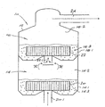
- a preferred embodiment of the invention is described by way of a non-limiting example, and with reference to the accompanying figure showing a cross-sectional side view of a vacuum pan in accordance with one embodiment of the invention.
- the vacuum pan 10 comprises a single vessel 12 that is divided into a first chamber 14, being an operatively lower chamber, and a second chamber 16, being an operatively upper chamber disposed immediately above the first chamber 14.
- the first chamber 14 includes a lower zone 14.1 for receiving a selected massecuite 14.3.
- a first heat exchanger or calandria 20 is located in the lower zone 14.1 in order to facilitate the transfer of heat to the massecuite 14.3.
- the first calandria 20 has an inlet 20.1 which is typically in flow communication with an external heat transfer medium, which may be an external supply of steam, or any other conventional vapour source as is known in the art.
- the vapour that evaporates from the massecuite 14.3 collects in a vapour space 14.2 of the first chamber 14.
- vapour space 14.2 Should there be a shortage of vapour generated in the vapour space 14.2 (less than is required in heat exchanger or calandria 22) then the vapour may be supplemented by steam from an external source (not shown). Similarly should there be a surplus of vapour in 14.2 then it may be diverted out to a condenser (by a connection to exit 24 - not shown)
- the second chamber 16 also includes a lower zone 16.1 for receiving a selected massecuite 16.3.
- the massecuite in the second chamber 16 may be the same as the massecuite in the first chamber 14, but may also be of a different composition.
- the first chamber may contain a first refinery massecuite
- the second chamber may contain a second refinery massecuite.
- a second heat exchanger or calandria 22 is located in the lower zone 16.1 of the second chamber 16 in order to facilitate the transfer of heat to the massecuite 16.3 in the second chamber 16.
- the second calandria 22 also has a heat transfer medium inlet 22.1, but importantly, the inlet 22.1 is in flow communication with the vapour space 14.2 of the first chamber, as is indicated by arrow A.
- the vapour in the first chamber 14 is therefore utilized as a heat transfer medium in the second calandria 22, as opposed to the second calandria 22 being in flow communication with an external supply of heat transfer medium as is known in the art.
- Vapour collecting in the vapour space 16.2 of the second chamber 16 can subsequently be utilized in other process steps, or condensed in a separate condenser, as is commonly practiced.
- the first chamber 14 and the second chamber 16 are isolated from one another, and can therefore advantageously be operated at different pressures. It is foreseen that the vapour space 14.2 of the first chamber 14 will be operated at a pressure that is higher than the pressure conventionally employed for such purposes, whereas the vapour space 16.2 of the second chamber 16 will be maintained at a pressure similar to that typically known in the art.
- the continuous vacuum pan described above has a number of novel and advantageous features.
- pan boiling operations are carried out in double-effect evaporation mode within the same vessel, rather than being carried out in different pans. This reduces cost and complexity and facilitates and simplifies the control of the process.
- vapour-spaces of the two chambers of the continuous pan are operated at different pressures.
- the operation of portions of a conventional continuous pan at two different vacuum pressures is usually costly to carry out, due to the high cost of isolating the two different pressures from each other. Due to the specific design of the double-calandria vertical continuous pan, this mode of operation is greatly simplified.
Landscapes
- Chemical & Material Sciences (AREA)
- Crystallography & Structural Chemistry (AREA)
- Chemical Kinetics & Catalysis (AREA)
- Life Sciences & Earth Sciences (AREA)
- Biochemistry (AREA)
- Organic Chemistry (AREA)
- Commercial Cooking Devices (AREA)
- Vaporization, Distillation, Condensation, Sublimation, And Cold Traps (AREA)
- Cookers (AREA)
- Drying Of Solid Materials (AREA)
- Details Of Rigid Or Semi-Rigid Containers (AREA)
- Containers Having Bodies Formed In One Piece (AREA)
Abstract
Description
- THIS invention relates to a continuous vacuum pan for use in the sugar processing industry, and more particularly but not exclusively, to a vertical, double calandria, continuous vacuum pan.
- In this specification the term "calandria" shall be interpreted to mean a shell and tube reboiler commonly used in continuous pans found in the sugar processing industry. The calandria may generally be of a floating or a fixed configuration, as is known in the art.
- During one particular stage of the sugar production process, syrup produced by evaporators (or molasses) is concentrated further in specially designed vessels known as pans. As the concentration rises the dissolved sugar crystallises and the function of the pan is to grow sugar crystals (from the sucrose in solution) in several steps to maximise the amount of sucrose recovered in raw sugar. It will be appreciated that this is a crucial step in the sugar production process, and hence much attention has been given to the design of pans, and in particular continuous vacuum pans, in recent times.
- A vacuum pan is essentially a vessel, operated under vacuum, in which sugar syrup or molasses is boiled in order to increase the sugar concentration, and thus resulting in the growth of sugar crystals in the two-phase mixture of crystals and the mother liquor from which they are crystallizing (so called massecuite). A calandria is generally used as a reboiler to heat and evaporate the syrup, and also to cause circulation of massecuite inside the vessel. Steam is supplied to the calandria via a steam inlet, and is conveyed between the tubes of the calandria, thus resulting in effective heat transfer from the calandria to the massecuite contained within the tubes. One particular continuous vacuum pan design is disclosed in the applicant's own prior patent,
US6,991,708 . - Energy efficiency is of critical importance in sugar factory design and operation, particularly for those factories that consume large quantities of fossil fuels (for example, stand-alone sugar refineries). The installation of continuous pans, as opposed to batch pans, facilitates energy savings, as the steady rate of steam consumption by these units leads to more efficient operation than with conventional batch pan technology. In addition, continuous pans may readily be operated using lower pressure vapour supplies than can be used in batch pans. This allows for more efficient integration of pan boiling operations into the energy scheme of the factory.
- To further enhance the energy efficiency of a continuous pan, use has sometimes been made of two separate vapour supplies within the same pan calandria. For example, some of the continuous pan compartments may be operated using vapour at a higher pressure, while other pan compartments requiring a lower rate of heat transfer may be operated using a second lower-pressure vapour supply. This design philosophy is generally implemented by using substantially separated vessels, in which each calandria is supplied by its own steam supply source.
- A number of authors have furthermore shown that energy efficiency benefits may be achieved in a sugar factory by carrying out various pan boiling operations in a double-effect evaporation mode. In such an arrangement, the pan vapour from a first set of vacuum pans is used to boil a second set of pans operating at a lower absolute pressure. Either batch pans or continuous pans may be employed in this scheme, although the use of continuous pans would greatly simplify the operation. The disadvantage of these proposed arrangements is that they essentially comprise independent pans that are arranged in a cascaded configuration, which is not optimal from a cost, efficiency and space point of view.
- It is therefore an object of the invention to provide a continuous vacuum pan that will, at least partially, overcome the above disadvantages.
- It is also an object of the invention to provide a continuous vacuum pan that will be a useful alternative to existing vacuum pans.
- It is a still further object of the invention to provide a continuous vacuum pan utilizing a vertical double calandria pan, and which also employs double effect pan boiling, which will result in substantial energy savings.
-
WO2007113849A WO 2009/49391 WO0191875A GB2147217A EP0403441A ,EP0201629A ,EP0065775A and HELUANE et al., "Enhancing sugar can process performance through optimal production scheduling", Chemical Engineering and Processing, vol. 46, No. 3, December 2006, all disclose a continuous vacuum pan comprising plural chambers in accordance with the preamble of claim 1. - According to the invention there is provided a continuous vacuum pan including:
- a vessel having a first enclosed chamber and a second enclosed chamber;
- a first heat exchanger located in the first chamber, with a first vapour space defined in the first chamber above the first heat exchanger; and
- a second heat exchanger located in the second chamber, with a second
- vapour space defined in the second chamber above the second heat exchanger;
- the first heat exchanger and the second heat exchanger both having heat transfer medium inlets;
- characterised in that the heat exchangers are in the form of floating calandrias and the heat transfer medium inlet of the second heat exchanger is in flow communication with the first vapour space, in order for vapour contained in the first vapour space to be conveyed through the second heat exchanger as heat transfer medium.
- There is provided for the inlet of the first heat exchanger to be in flow communication with an external high temperature heat transfer medium.
- Preferably, the second enclosed chamber is operatively above the first enclosed chamber.
- The heat transfer medium may be steam, or any other conventional vapour source used in pan boiling operations.
- Preferably the continuous vacuum pan is the vacuum pan as disclosed in
US 6,991,708 , but with the steam supply configuration as described hereinbefore. - There is also provided for the two chambers to be isolated from one another, and to be operated at different pressures.
- A preferred embodiment of the invention is described by way of a non-limiting example, and with reference to the accompanying figure showing a cross-sectional side view of a vacuum pan in accordance with one embodiment of the invention.
- Referring to the drawings, in which like numerals indicate like features, a non-limiting example of a continuous vacuum pan in accordance with the invention is generally indicated by reference numeral 10.
- The vacuum pan 10 comprises a
single vessel 12 that is divided into afirst chamber 14, being an operatively lower chamber, and asecond chamber 16, being an operatively upper chamber disposed immediately above thefirst chamber 14. - The
first chamber 14 includes a lower zone 14.1 for receiving a selected massecuite 14.3. A first heat exchanger orcalandria 20 is located in the lower zone 14.1 in order to facilitate the transfer of heat to the massecuite 14.3. Thefirst calandria 20 has an inlet 20.1 which is typically in flow communication with an external heat transfer medium, which may be an external supply of steam, or any other conventional vapour source as is known in the art. The vapour that evaporates from the massecuite 14.3 collects in a vapour space 14.2 of thefirst chamber 14. - Should there be a shortage of vapour generated in the vapour space 14.2 (less than is required in heat exchanger or calandria 22) then the vapour may be supplemented by steam from an external source (not shown). Similarly should there be a surplus of vapour in 14.2 then it may be diverted out to a condenser (by a connection to exit 24 - not shown)
- The
second chamber 16 also includes a lower zone 16.1 for receiving a selected massecuite 16.3. The massecuite in thesecond chamber 16 may be the same as the massecuite in thefirst chamber 14, but may also be of a different composition. For example, the first chamber may contain a first refinery massecuite, whereas the second chamber may contain a second refinery massecuite. A second heat exchanger orcalandria 22 is located in the lower zone 16.1 of thesecond chamber 16 in order to facilitate the transfer of heat to the massecuite 16.3 in thesecond chamber 16. - The
second calandria 22 also has a heat transfer medium inlet 22.1, but importantly, the inlet 22.1 is in flow communication with the vapour space 14.2 of the first chamber, as is indicated by arrow A. The vapour in thefirst chamber 14 is therefore utilized as a heat transfer medium in thesecond calandria 22, as opposed to thesecond calandria 22 being in flow communication with an external supply of heat transfer medium as is known in the art. Vapour collecting in the vapour space 16.2 of thesecond chamber 16 can subsequently be utilized in other process steps, or condensed in a separate condenser, as is commonly practiced. - The
first chamber 14 and thesecond chamber 16 are isolated from one another, and can therefore advantageously be operated at different pressures. It is foreseen that the vapour space 14.2 of thefirst chamber 14 will be operated at a pressure that is higher than the pressure conventionally employed for such purposes, whereas the vapour space 16.2 of thesecond chamber 16 will be maintained at a pressure similar to that typically known in the art. - The continuous vacuum pan described above has a number of novel and advantageous features.
- Firstly, the pan boiling operations are carried out in double-effect evaporation mode within the same vessel, rather than being carried out in different pans. This reduces cost and complexity and facilitates and simplifies the control of the process.
- Secondly, the vapour-spaces of the two chambers of the continuous pan are operated at different pressures. The operation of portions of a conventional continuous pan at two different vacuum pressures is usually costly to carry out, due to the high cost of isolating the two different pressures from each other. Due to the specific design of the double-calandria vertical continuous pan, this mode of operation is greatly simplified.
- It is also foreseen that the invention will be implemented very effectively in the applicant's double-calandria vertical continuous pan, as is disclosed in
US 6,991,708 as the normally equal sizing of the two chambers of the pan ensure that the vapour produced in the first chamber will closely match the steam requirement of the second chamber. Any mismatch in steam supply/demand can be accommodated by a partial bypass or let-down of steam.
Claims (4)
- A continuous vacuum pan (10) including:a vessel (12) having a first enclosed chamber (14) and a second enclosed chamber (16);a first heat exchanger (20) located in the first chamber, with a first vapour space (14.2) defined in the first chamber above the first heat exchanger; anda second heat exchanger (16.2) located in the second chamber, with a second vapour space defined in the second chamber above the second heat exchanger;the first heat exchanger and the second heat exchanger both having heat transfer medium inlets (20.1, 22.1);characterised in that the heat exchangers are in the form of floating calandrias and the heat transfer medium inlet of the second heat exchanger is in flow communication with the first vapour space, in order for vapour contained in the first vapour space to be conveyed through the second heat exchanger as heat transfer medium.
- The continuous vacuum pan of claim 1, in which the inlet (20.1) of the first heat exchanger (20) is in flow communication with an external high temperature heat transfer medium.
- The continuous vacuum pan of claim 2, wherein the heat transfer medium is steam.
- The continuous vacuum pan of any one of the preceding claims wherein the two chambers (14, 16) are isolated from one another, in order to be operated at different pressures.
Applications Claiming Priority (2)
| Application Number | Priority Date | Filing Date | Title |
|---|---|---|---|
| ZA200808362 | 2008-10-01 | ||
| PCT/IB2009/053961 WO2010038160A2 (en) | 2008-10-01 | 2009-09-10 | Continuous vacuum pan |
Publications (2)
| Publication Number | Publication Date |
|---|---|
| EP2334828A2 EP2334828A2 (en) | 2011-06-22 |
| EP2334828B1 true EP2334828B1 (en) | 2012-08-15 |
Family
ID=41351570
Family Applications (1)
| Application Number | Title | Priority Date | Filing Date |
|---|---|---|---|
| EP09787163A Not-in-force EP2334828B1 (en) | 2008-10-01 | 2009-09-10 | Continuous vacuum pan |
Country Status (7)
| Country | Link |
|---|---|
| US (1) | US20110297331A1 (en) |
| EP (1) | EP2334828B1 (en) |
| CN (1) | CN102227508A (en) |
| AU (1) | AU2009299470B2 (en) |
| CO (1) | CO6390011A2 (en) |
| WO (1) | WO2010038160A2 (en) |
| ZA (1) | ZA201104559B (en) |
Families Citing this family (1)
| Publication number | Priority date | Publication date | Assignee | Title |
|---|---|---|---|---|
| CN103585774B (en) * | 2012-08-17 | 2015-05-27 | 宏芳香料(昆山)有限公司 | Negative pressure steam heating apparatus and heating method thereof |
Family Cites Families (13)
| Publication number | Priority date | Publication date | Assignee | Title |
|---|---|---|---|---|
| US1799478A (en) * | 1925-02-05 | 1931-04-07 | David D Peebles | Method of evaporating liquids and apparatus therefor |
| FR1526887A (en) * | 1966-09-16 | 1968-05-31 | S I C E R Soc Ind Et Commercia | Improvements to candy cooking appliances |
| FR1581088A (en) * | 1968-07-17 | 1969-09-12 | ||
| AU1729776A (en) * | 1975-09-01 | 1978-03-09 | Csr Ltd | Semi-continuous vacuum pan system |
| DE3120732A1 (en) * | 1981-05-25 | 1982-12-09 | Erich Prof. Dr. 3340 Wolfenbüttel Reinefeld | "METHOD AND DEVICE FOR CONTINUOUS EVAPORATION CRYSTALIZATION" |
| IT1172938B (en) * | 1983-09-30 | 1987-06-18 | Eridania | PROCEDURE AND DEVICE FOR CONTINUOUS WHOLESALE OF PRE-FORMED CRYSTALS IN MEDIUM AND HIGH PURITY MIXTURES IN SUGAR FACTORY |
| DE3517511A1 (en) * | 1985-05-15 | 1986-11-20 | Selwig & Lange GmbH, 3300 Braunschweig | COOLING CRYSTALIZATION TOWER FOR SUGAR MAGMA |
| IT1232751B (en) * | 1989-06-14 | 1992-03-05 | Eridania | PROCEDURE AND DEVICE FOR THE CONTINUOUS WHOLESALE OF THE PREFORMED MASSECOTTE CRYSTALS |
| DE29503589U1 (en) * | 1995-03-03 | 1995-04-27 | Balcke Duerr Ag | Evaporator |
| DE59909532D1 (en) * | 1999-11-04 | 2004-06-24 | Balcke Duerr Energietech Gmbh | Evaporator |
| DE60115434T2 (en) | 2000-06-01 | 2006-06-14 | Tongaat Hulett Group Ltd | CONTINUOUS EVAPORATING CRYSTALLIZER |
| WO2007113849A1 (en) * | 2006-03-30 | 2007-10-11 | Spray Engineering Devices Limited | Improved vertical continuous vacuum pan |
| BRPI0705181A2 (en) * | 2007-10-16 | 2009-06-16 | Dedini Sa Ind De Base | process and equipment for controlled cooling sugar crystallization |
-
2009
- 2009-09-10 WO PCT/IB2009/053961 patent/WO2010038160A2/en not_active Ceased
- 2009-09-10 AU AU2009299470A patent/AU2009299470B2/en not_active Ceased
- 2009-09-10 EP EP09787163A patent/EP2334828B1/en not_active Not-in-force
- 2009-09-10 CN CN2009801478291A patent/CN102227508A/en active Pending
- 2009-09-10 US US13/125,243 patent/US20110297331A1/en not_active Abandoned
-
2011
- 2011-04-20 CO CO11049726A patent/CO6390011A2/en active IP Right Grant
- 2011-06-21 ZA ZA2011/04559A patent/ZA201104559B/en unknown
Also Published As
| Publication number | Publication date |
|---|---|
| EP2334828A2 (en) | 2011-06-22 |
| AU2009299470A1 (en) | 2010-04-08 |
| US20110297331A1 (en) | 2011-12-08 |
| CN102227508A (en) | 2011-10-26 |
| CO6390011A2 (en) | 2012-02-29 |
| WO2010038160A3 (en) | 2010-10-28 |
| AU2009299470B2 (en) | 2013-09-26 |
| WO2010038160A2 (en) | 2010-04-08 |
| ZA201104559B (en) | 2012-08-29 |
Similar Documents
| Publication | Publication Date | Title |
|---|---|---|
| CN101896241A (en) | Method and apparatus for crystallizing sugar by controlled cooling | |
| EP2885434B1 (en) | Process for refining impure crystallised sucrose | |
| CN104692415A (en) | Evaporative crystallization method of ammonium chloride in potassium nitrate production | |
| EP0478586B1 (en) | Multistage evaporating system | |
| CN114797145B (en) | Differential pressure thermal coupling rectification process for coal-to-ethylene glycol byproduct | |
| AU2009299470B2 (en) | Continuous vacuum pan | |
| CN217909007U (en) | Cellulose solvent recovery device | |
| US4132588A (en) | Concentration process by multistage, multiple effect evaporator | |
| AU2011357643A1 (en) | Process for producing ethanol from the fermentation of sugar sources in a fermentation medium with high ethanol content | |
| US5209856A (en) | Process and device for continuous crystallization of a massecuite | |
| EP1999281B1 (en) | Improved vertical continuous vacuum pan | |
| CN115245687B (en) | Five-effect evaporation system for sugar production and use method | |
| RU2092215C1 (en) | Method of boiling-down of aluminate solutions and device for its embodiment | |
| EP4239084B1 (en) | A continuous vacuum crystallizer and a method of crystallizing sugar | |
| Koç et al. | Evaporation in the sugar industry | |
| CN222641248U (en) | Alumina evaporation system | |
| CN213466794U (en) | Amino acid concentration system | |
| US10927422B2 (en) | Stacked continuous vacuum pan system and method | |
| BRPI1101665A2 (en) | continuous vacuum tank | |
| CN120082676A (en) | Gas Method for Sugar Production | |
| Temerk et al. | Execute of Cooling Vacuum Crystallization (CVC) in Place of C-Cooling Crystallizers for White Sugar Production and Energy Saving in the Beet Sugar Industry | |
| RU2229323C1 (en) | Multi-effect counter-flow evaporating system for concentration of aluminate solution | |
| BRPI0905395B1 (en) | process for ethanol production from fermentation of sugar sources in fermentation medium with high ethanol content | |
| WO2011086573A1 (en) | An efficient energy conservation system and device for manufacture of sugar from sugar cane | |
| JPS6394963A (en) | Continuous production of volatile fermentation product |
Legal Events
| Date | Code | Title | Description |
|---|---|---|---|
| PUAI | Public reference made under article 153(3) epc to a published international application that has entered the european phase |
Free format text: ORIGINAL CODE: 0009012 |
|
| 17P | Request for examination filed |
Effective date: 20110421 |
|
| AK | Designated contracting states |
Kind code of ref document: A2 Designated state(s): AT BE BG CH CY CZ DE DK EE ES FI FR GB GR HR HU IE IS IT LI LT LU LV MC MK MT NL NO PL PT RO SE SI SK SM TR |
|
| AX | Request for extension of the european patent |
Extension state: AL BA RS |
|
| DAX | Request for extension of the european patent (deleted) | ||
| REG | Reference to a national code |
Ref country code: DE Ref legal event code: R079 Ref document number: 602009009088 Country of ref document: DE Free format text: PREVIOUS MAIN CLASS: C13F0001020000 Ipc: C13B0030020000 |
|
| GRAP | Despatch of communication of intention to grant a patent |
Free format text: ORIGINAL CODE: EPIDOSNIGR1 |
|
| RIC1 | Information provided on ipc code assigned before grant |
Ipc: B01D 9/00 20060101ALI20120116BHEP Ipc: C13B 30/02 20110101AFI20120116BHEP |
|
| GRAS | Grant fee paid |
Free format text: ORIGINAL CODE: EPIDOSNIGR3 |
|
| GRAA | (expected) grant |
Free format text: ORIGINAL CODE: 0009210 |
|
| AK | Designated contracting states |
Kind code of ref document: B1 Designated state(s): AT BE BG CH CY CZ DE DK EE ES FI FR GB GR HR HU IE IS IT LI LT LU LV MC MK MT NL NO PL PT RO SE SI SK SM TR |
|
| REG | Reference to a national code |
Ref country code: AT Ref legal event code: REF Ref document number: 570886 Country of ref document: AT Kind code of ref document: T Effective date: 20120815 Ref country code: GB Ref legal event code: FG4D Ref country code: CH Ref legal event code: EP |
|
| REG | Reference to a national code |
Ref country code: IE Ref legal event code: FG4D |
|
| REG | Reference to a national code |
Ref country code: DE Ref legal event code: R096 Ref document number: 602009009088 Country of ref document: DE Effective date: 20121011 |
|
| REG | Reference to a national code |
Ref country code: NL Ref legal event code: VDEP Effective date: 20120815 |
|
| REG | Reference to a national code |
Ref country code: AT Ref legal event code: MK05 Ref document number: 570886 Country of ref document: AT Kind code of ref document: T Effective date: 20120815 |
|
| PG25 | Lapsed in a contracting state [announced via postgrant information from national office to epo] |
Ref country code: FI Free format text: LAPSE BECAUSE OF FAILURE TO SUBMIT A TRANSLATION OF THE DESCRIPTION OR TO PAY THE FEE WITHIN THE PRESCRIBED TIME-LIMIT Effective date: 20120815 Ref country code: NO Free format text: LAPSE BECAUSE OF FAILURE TO SUBMIT A TRANSLATION OF THE DESCRIPTION OR TO PAY THE FEE WITHIN THE PRESCRIBED TIME-LIMIT Effective date: 20121115 Ref country code: IS Free format text: LAPSE BECAUSE OF FAILURE TO SUBMIT A TRANSLATION OF THE DESCRIPTION OR TO PAY THE FEE WITHIN THE PRESCRIBED TIME-LIMIT Effective date: 20121215 Ref country code: HR Free format text: LAPSE BECAUSE OF FAILURE TO SUBMIT A TRANSLATION OF THE DESCRIPTION OR TO PAY THE FEE WITHIN THE PRESCRIBED TIME-LIMIT Effective date: 20120815 Ref country code: LT Free format text: LAPSE BECAUSE OF FAILURE TO SUBMIT A TRANSLATION OF THE DESCRIPTION OR TO PAY THE FEE WITHIN THE PRESCRIBED TIME-LIMIT Effective date: 20120815 Ref country code: AT Free format text: LAPSE BECAUSE OF FAILURE TO SUBMIT A TRANSLATION OF THE DESCRIPTION OR TO PAY THE FEE WITHIN THE PRESCRIBED TIME-LIMIT Effective date: 20120815 |
|
| PG25 | Lapsed in a contracting state [announced via postgrant information from national office to epo] |
Ref country code: SI Free format text: LAPSE BECAUSE OF FAILURE TO SUBMIT A TRANSLATION OF THE DESCRIPTION OR TO PAY THE FEE WITHIN THE PRESCRIBED TIME-LIMIT Effective date: 20120815 Ref country code: PT Free format text: LAPSE BECAUSE OF FAILURE TO SUBMIT A TRANSLATION OF THE DESCRIPTION OR TO PAY THE FEE WITHIN THE PRESCRIBED TIME-LIMIT Effective date: 20121217 Ref country code: LV Free format text: LAPSE BECAUSE OF FAILURE TO SUBMIT A TRANSLATION OF THE DESCRIPTION OR TO PAY THE FEE WITHIN THE PRESCRIBED TIME-LIMIT Effective date: 20120815 Ref country code: BE Free format text: LAPSE BECAUSE OF FAILURE TO SUBMIT A TRANSLATION OF THE DESCRIPTION OR TO PAY THE FEE WITHIN THE PRESCRIBED TIME-LIMIT Effective date: 20120815 Ref country code: GR Free format text: LAPSE BECAUSE OF FAILURE TO SUBMIT A TRANSLATION OF THE DESCRIPTION OR TO PAY THE FEE WITHIN THE PRESCRIBED TIME-LIMIT Effective date: 20121116 Ref country code: PL Free format text: LAPSE BECAUSE OF FAILURE TO SUBMIT A TRANSLATION OF THE DESCRIPTION OR TO PAY THE FEE WITHIN THE PRESCRIBED TIME-LIMIT Effective date: 20120815 Ref country code: SE Free format text: LAPSE BECAUSE OF FAILURE TO SUBMIT A TRANSLATION OF THE DESCRIPTION OR TO PAY THE FEE WITHIN THE PRESCRIBED TIME-LIMIT Effective date: 20120815 |
|
| PG25 | Lapsed in a contracting state [announced via postgrant information from national office to epo] |
Ref country code: NL Free format text: LAPSE BECAUSE OF FAILURE TO SUBMIT A TRANSLATION OF THE DESCRIPTION OR TO PAY THE FEE WITHIN THE PRESCRIBED TIME-LIMIT Effective date: 20120815 |
|
| PG25 | Lapsed in a contracting state [announced via postgrant information from national office to epo] |
Ref country code: CZ Free format text: LAPSE BECAUSE OF FAILURE TO SUBMIT A TRANSLATION OF THE DESCRIPTION OR TO PAY THE FEE WITHIN THE PRESCRIBED TIME-LIMIT Effective date: 20120815 Ref country code: MC Free format text: LAPSE BECAUSE OF NON-PAYMENT OF DUE FEES Effective date: 20120930 Ref country code: RO Free format text: LAPSE BECAUSE OF FAILURE TO SUBMIT A TRANSLATION OF THE DESCRIPTION OR TO PAY THE FEE WITHIN THE PRESCRIBED TIME-LIMIT Effective date: 20120815 Ref country code: ES Free format text: LAPSE BECAUSE OF FAILURE TO SUBMIT A TRANSLATION OF THE DESCRIPTION OR TO PAY THE FEE WITHIN THE PRESCRIBED TIME-LIMIT Effective date: 20121126 Ref country code: EE Free format text: LAPSE BECAUSE OF FAILURE TO SUBMIT A TRANSLATION OF THE DESCRIPTION OR TO PAY THE FEE WITHIN THE PRESCRIBED TIME-LIMIT Effective date: 20120815 Ref country code: DK Free format text: LAPSE BECAUSE OF FAILURE TO SUBMIT A TRANSLATION OF THE DESCRIPTION OR TO PAY THE FEE WITHIN THE PRESCRIBED TIME-LIMIT Effective date: 20120815 |
|
| PG25 | Lapsed in a contracting state [announced via postgrant information from national office to epo] |
Ref country code: SK Free format text: LAPSE BECAUSE OF FAILURE TO SUBMIT A TRANSLATION OF THE DESCRIPTION OR TO PAY THE FEE WITHIN THE PRESCRIBED TIME-LIMIT Effective date: 20120815 Ref country code: IT Free format text: LAPSE BECAUSE OF FAILURE TO SUBMIT A TRANSLATION OF THE DESCRIPTION OR TO PAY THE FEE WITHIN THE PRESCRIBED TIME-LIMIT Effective date: 20120815 |
|
| REG | Reference to a national code |
Ref country code: IE Ref legal event code: MM4A |
|
| PLBE | No opposition filed within time limit |
Free format text: ORIGINAL CODE: 0009261 |
|
| STAA | Information on the status of an ep patent application or granted ep patent |
Free format text: STATUS: NO OPPOSITION FILED WITHIN TIME LIMIT |
|
| 26N | No opposition filed |
Effective date: 20130516 |
|
| PG25 | Lapsed in a contracting state [announced via postgrant information from national office to epo] |
Ref country code: BG Free format text: LAPSE BECAUSE OF FAILURE TO SUBMIT A TRANSLATION OF THE DESCRIPTION OR TO PAY THE FEE WITHIN THE PRESCRIBED TIME-LIMIT Effective date: 20121115 Ref country code: IE Free format text: LAPSE BECAUSE OF NON-PAYMENT OF DUE FEES Effective date: 20120910 |
|
| REG | Reference to a national code |
Ref country code: DE Ref legal event code: R097 Ref document number: 602009009088 Country of ref document: DE Effective date: 20130516 |
|
| PG25 | Lapsed in a contracting state [announced via postgrant information from national office to epo] |
Ref country code: CY Free format text: LAPSE BECAUSE OF FAILURE TO SUBMIT A TRANSLATION OF THE DESCRIPTION OR TO PAY THE FEE WITHIN THE PRESCRIBED TIME-LIMIT Effective date: 20120815 Ref country code: MT Free format text: LAPSE BECAUSE OF FAILURE TO SUBMIT A TRANSLATION OF THE DESCRIPTION OR TO PAY THE FEE WITHIN THE PRESCRIBED TIME-LIMIT Effective date: 20120815 |
|
| PG25 | Lapsed in a contracting state [announced via postgrant information from national office to epo] |
Ref country code: TR Free format text: LAPSE BECAUSE OF FAILURE TO SUBMIT A TRANSLATION OF THE DESCRIPTION OR TO PAY THE FEE WITHIN THE PRESCRIBED TIME-LIMIT Effective date: 20120815 |
|
| REG | Reference to a national code |
Ref country code: CH Ref legal event code: PL |
|
| PG25 | Lapsed in a contracting state [announced via postgrant information from national office to epo] |
Ref country code: SM Free format text: LAPSE BECAUSE OF FAILURE TO SUBMIT A TRANSLATION OF THE DESCRIPTION OR TO PAY THE FEE WITHIN THE PRESCRIBED TIME-LIMIT Effective date: 20120815 Ref country code: LU Free format text: LAPSE BECAUSE OF NON-PAYMENT OF DUE FEES Effective date: 20120910 |
|
| PG25 | Lapsed in a contracting state [announced via postgrant information from national office to epo] |
Ref country code: CH Free format text: LAPSE BECAUSE OF NON-PAYMENT OF DUE FEES Effective date: 20130930 Ref country code: LI Free format text: LAPSE BECAUSE OF NON-PAYMENT OF DUE FEES Effective date: 20130930 Ref country code: HU Free format text: LAPSE BECAUSE OF FAILURE TO SUBMIT A TRANSLATION OF THE DESCRIPTION OR TO PAY THE FEE WITHIN THE PRESCRIBED TIME-LIMIT Effective date: 20090910 |
|
| PG25 | Lapsed in a contracting state [announced via postgrant information from national office to epo] |
Ref country code: MK Free format text: LAPSE BECAUSE OF FAILURE TO SUBMIT A TRANSLATION OF THE DESCRIPTION OR TO PAY THE FEE WITHIN THE PRESCRIBED TIME-LIMIT Effective date: 20120815 |
|
| REG | Reference to a national code |
Ref country code: FR Ref legal event code: PLFP Year of fee payment: 8 |
|
| REG | Reference to a national code |
Ref country code: FR Ref legal event code: PLFP Year of fee payment: 9 |
|
| REG | Reference to a national code |
Ref country code: FR Ref legal event code: PLFP Year of fee payment: 10 |
|
| PGFP | Annual fee paid to national office [announced via postgrant information from national office to epo] |
Ref country code: DE Payment date: 20180828 Year of fee payment: 10 Ref country code: FR Payment date: 20180813 Year of fee payment: 10 |
|
| PGFP | Annual fee paid to national office [announced via postgrant information from national office to epo] |
Ref country code: GB Payment date: 20180905 Year of fee payment: 10 |
|
| REG | Reference to a national code |
Ref country code: DE Ref legal event code: R119 Ref document number: 602009009088 Country of ref document: DE |
|
| PG25 | Lapsed in a contracting state [announced via postgrant information from national office to epo] |
Ref country code: DE Free format text: LAPSE BECAUSE OF NON-PAYMENT OF DUE FEES Effective date: 20200401 |
|
| GBPC | Gb: european patent ceased through non-payment of renewal fee |
Effective date: 20190910 |
|
| PG25 | Lapsed in a contracting state [announced via postgrant information from national office to epo] |
Ref country code: FR Free format text: LAPSE BECAUSE OF NON-PAYMENT OF DUE FEES Effective date: 20190930 Ref country code: GB Free format text: LAPSE BECAUSE OF NON-PAYMENT OF DUE FEES Effective date: 20190910 |