EP2334475B1 - Razor handles to be realeasably connected to shaving cartridges and razors including such handles. - Google Patents
Razor handles to be realeasably connected to shaving cartridges and razors including such handles. Download PDFInfo
- Publication number
- EP2334475B1 EP2334475B1 EP08804976.2A EP08804976A EP2334475B1 EP 2334475 B1 EP2334475 B1 EP 2334475B1 EP 08804976 A EP08804976 A EP 08804976A EP 2334475 B1 EP2334475 B1 EP 2334475B1
- Authority
- EP
- European Patent Office
- Prior art keywords
- slide element
- yoke
- razor
- shaving cartridge
- handle body
- Prior art date
- Legal status (The legal status is an assumption and is not a legal conclusion. Google has not performed a legal analysis and makes no representation as to the accuracy of the status listed.)
- Active
Links
- 230000035939 shock Effects 0.000 description 5
- 239000000463 material Substances 0.000 description 2
- 230000003247 decreasing effect Effects 0.000 description 1
- 230000000717 retained effect Effects 0.000 description 1
- 238000000926 separation method Methods 0.000 description 1
Images


Classifications
-
- B—PERFORMING OPERATIONS; TRANSPORTING
- B26—HAND CUTTING TOOLS; CUTTING; SEVERING
- B26B—HAND-HELD CUTTING TOOLS NOT OTHERWISE PROVIDED FOR
- B26B21/00—Razors of the open or knife type; Safety razors or other shaving implements of the planing type; Hair-trimming devices involving a razor-blade; Equipment therefor
- B26B21/40—Details or accessories
- B26B21/52—Handles, e.g. tiltable, flexible
- B26B21/521—Connection details, e.g. connection to razor heads
-
- B—PERFORMING OPERATIONS; TRANSPORTING
- B26—HAND CUTTING TOOLS; CUTTING; SEVERING
- B26B—HAND-HELD CUTTING TOOLS NOT OTHERWISE PROVIDED FOR
- B26B21/00—Razors of the open or knife type; Safety razors or other shaving implements of the planing type; Hair-trimming devices involving a razor-blade; Equipment therefor
- B26B21/08—Razors of the open or knife type; Safety razors or other shaving implements of the planing type; Hair-trimming devices involving a razor-blade; Equipment therefor involving changeable blades
- B26B21/14—Safety razors with one or more blades arranged transversely to the handle
- B26B21/22—Safety razors with one or more blades arranged transversely to the handle involving several blades to be used simultaneously
-
- B—PERFORMING OPERATIONS; TRANSPORTING
- B26—HAND CUTTING TOOLS; CUTTING; SEVERING
- B26B—HAND-HELD CUTTING TOOLS NOT OTHERWISE PROVIDED FOR
- B26B21/00—Razors of the open or knife type; Safety razors or other shaving implements of the planing type; Hair-trimming devices involving a razor-blade; Equipment therefor
- B26B21/40—Details or accessories
Definitions
- the invention is concerned with razor handles to be releasably connected to shaving cartridges and razors including such handles.
- a razor handle comprising:
- Such a razor handle allows a shaving cartridge connected to it to be retained and to be released after use. After one or several use, the user can through the shaving cartridge and keep the razor handle on which he can connect a new shaving cartridge.
- the razor handle has a body provided with a flexible yoke able to flex according to the sliding of an actuator cooperating with the body to facilitate receiving and retaining a shaving cartridge in pivotal and releasable fashion in the yoke.
- the use of such a razor may be dangerous for the user, especially because he or she can cut himself/herself with the blade edge(s) of the shaving cartridge. This risk can occur with children manipulating such a razor or more specifically when travelling, since the razor can be exposed to several shocks leading to the accidental release of the shaving cartridge. Indeed, when the user wants to take his/her razor in his/her bag, he may catch the shaving cartridge and cut himself.
- One objective of the present invention is to avoid these drawbacks.
- the razor handle further comprises a stop element to prevent the yoke from inadvertently flexing when the slide element is in the rest position.
- the shaving cartridge cannot be released.
- the invention also concerns a razor comprising such a razor handle connected to a shaving cartridge.
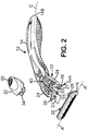
- FIG 1A illustrates a razor 10 comprising a razor handle 12 having a handle body 14 releasably retaining a disposable shaving cartridge 16.
- the handle body 14 preferably molded out of a plastic material is preferably elongated and extends along a longitudinal direction C-C between a front end 14A and a back end 14B.
- the shaving cartridge 16 is provided with one or more blades 18 each having a blade edge 18A extending parallel to a pivot axis A-A which is perpendicular to the longitudinal direction C-C when the shaving cartridge 16 is connected to the razor handle 12.
- the razor handle 12 further comprises a slide element 20 lockingly connected to the razor handle 12 (as disclosed in details hereafter) and movable between a rest position depicted on Figure 1A and a release position depicted on Figure 1B , and vice versa.
- the slide element 20 In its rest position ( Figure 1A ) the slide element 20 may be located backward toward the back end 14B of the handle body 14, whereas in its release position ( Figure 1B ) it may be located forward toward the front end 14A of the handle body 14.
- the handle body 14 is terminating in a flexible yoke 22 extending forward for receiving and releasably retaining the shaving cartridge 16 as depicted on Figure 1A .
- the yoke 22 may comprises two flexible arms 24 extending forward from both sides of the longitudinal direction C-C. The yoke 22 is in its open position, when the slide element 20 is in its rest position; whereas it flexes when the slide element 20 is in its release position.
- Each arm 24 may be provided with connecting means allowing their connection to respective connecting means provided on the shaving cartridge 16.
- These connecting means are those usually used to pivotably connect a shaving cartridge; they may for instance be journal bearings, shell-bearings, etc.
- a well-known shell-bearing 26 is provided on the free ends of each of the two arms 24 extending forward toward the shaving cartridge 16.
- These shell-bearings 26 can be connected to corresponding rearwardly protruding connectors 28 shaped arcuate and provided on the shaving cartridge 16 (as best seen on Figures 1B and 2 ). This connection can be of any other known type and is not detailed here.
- the handle body 14 may further be provided with an elastic tongue 30 for biasing the shaving cartridge 16 toward a rest position.
- This elastic tongue 30 is molded as a single piece with the handle body 14 and extends preferably centrally along the longitudinal direction C-C.
- This elastic tongue 30 extends preferably beyond the shell-bearings 26; more precisely the tip 31 the further ahead of the elastic tongue 30 is closer to the pivot axis A-A, than any part of the shell-bearings 26 or of the flanges 27 extending from the shell-bearings 26 laterally in a plan perpendicular to the pivot axis A-A.
- Said elastic tongue 30 may be provided with a twin-cam follower 30A cooperating with corresponding cam surfaces 32 provided on the shaving cartridge 16 to allow a pivoting of the last in two directions, the rest position corresponding for instance to the midway position.
- the elastic tongue may however be provided with a single-cam follower (not illustrated) cooperating with a corresponding cam surface provided on the shaving cartridge to allow a pivoting of the last only in one single direction.
- the slide element 20 is further provided with a pusher 34 to push a shaving cartridge 16 connected to the razor handle 12 away from the handle body 14.
- a pusher 34 to push a shaving cartridge 16 connected to the razor handle 12 away from the handle body 14.
- a spring member is further provided on the razor handle 12 to return the slide element 20 from the release position (depicted on Figure 1B ) to the rest position (depicted on Figure 1A ). More specifically, this spring member comprises a leaf spring 36 provided on the slide element 20 and bearing against a bearing surface 38 provided on the handle body 14 (as best seen on Figures 3A , 3B , 4A and 4B ).
- a central groove 40 provided on the handle body 14 forms a recess receiving the leaf spring 36.
- the central groove 40 is provided with a rib which forms the bearing surface 38 and which may have an oblique form.
- this bearing surface 38 provides a power source for the leaf spring 36 to return the slide element 20 from the release position back to its rest position.
- the leaf spring 36 more specifically its free end 36A is in contact with the bearing surface 38 in the rest position; when the slide element 20 is pushed forward to its release position, the leaf spring 36 begin to elastically deform and stores energy as long as the force exerted on the slide element 20 occurs (user pushing the slide element 20). This stored energy will be released since the force exerted on the slide element 20 stops and the slide element 20 will naturally slide back to its rest position.
- the handle body 14 may further be provided with a pair of elongated tracks 42 located on both sides of the central groove 40 and extending along the longitudinal direction C-C (see Figure 5 ).
- the slide element 20 may further be provided with projections 44 (see Figure 6 ) movable linearly along said tracks 42 to guide the slide element 20 in sliding movement relative to the handle body 14.
- the slide element 20 further comprises latch elements 46. More precisely, the latch elements 46 comprise two hooks 46 extending inside the central groove 40 on both sides of the longitudinal direction C-C and snapping with corresponding elongated lips 48 provided on the handle body 14 as best seen on Figure 7 .
- the slide element 20 is snap-fitted on the handle body 14. Actually, when mounting the slide element 20 on the handle body 14, the hooks 46 are pressed together in order to be introduced inside the central groove 40 and slide along the lateral faces of the lips 48. Meanwhile the slide element 20 is pressed toward the upper face of the handle body until the hooks 46 arrive at the free end 48' of the lips, where the hooks depart from one another and cover the free end 48' of the lips 48 forming a shoulder.
- each of the two arms 24 provided on the handle body 14 may be provided with a cam-follower 50 and the slide element may further comprise two cams 52, the cam-followers 50 being driven by said cams 52 to flex the arms 24 when the slide element 20 is pushed forward in its release position.
- Each of the cam-followers 50 comprises a non-linear surface 50. More specifically, the cams 52 engage the cam-followers 50 to drive the arms 24.
- the cam-followers 50 are preferably leaning away from one another from back to front with regard to the longitudinal direction C-C such that when the slide element 20 moves forward in its release position, the yoke 22 flexes inwardly; whereas when the slide element 20 returns rearward in its rest position, the yoke 22 deviates back in its open position.
- each cam-follower 50 is further provided with a bulge 54 providing a resistance to the movement of the cams 52.
- each cam-follower 50 was separated in two parts by the bulge 54, a front part 50A corresponding to the forward-most part and a back part 50B corresponding to the rearward-most part.
- the cams 52 are located in the back part 50B and are preferably in contact with or at least near the bulges 54; whereas, in the release position (see Figures 4B and 8B ), the cams 52 are located in the front part 50A.
- the razor handle 12 is further provided with a stop element.
- the stop element comprises preferably two locators 56 provided on the slide element 20 and an inner surface 58 provided on each of the two arms 24 against which the corresponding locator 56 abuts in the rest position.
- the two locators 56 extend toward the bottom part of the razor handle 12 in being lined on both sides of the longitudinal direction C-C. More precisely, the two locators 56 are located on both sides of the elastic tongue 30. The locators 56 are located symmetrically with regard to the longitudinal direction C-C and are separated from each other of a distance D56 taken between the two external (extreme) faces 56' of the locators 56.
- Each inner surface 58 is like a longitudinal flange extending laterally on both side of the longitudinal direction C-C.
- the inner surfaces 58 are located symmetrically with regard to the longitudinal direction C-C and are separated from each other of a distance D58 equal or a little bit greater than the distance D56 separating the locators 56.
- the relationship between the values of D58 to D56 is comprised between 1 to 10%, more preferably of about 5%.
- the distance D58 of the inner surfaces 58 is smaller in the release position, where the arms 24 are flexed, than in the rest position.
- the length L58, respectively L56, the shape and the location of the inner surfaces 58, respectively of the locators 56, is chosen by the skilled person such that the inner surfaces 58 abut against the locators 56 only when the arms 24 are pressed together while the slide element is in its rest position.
- the locators 56 which have preferably a rectangular-shape are completely retracted and substantially located in front of the inner surfaces 58 which are preferably plane; meaning that the forward-most part 56A of the locators 56 is more or less in front of a part of the inner surfaces 58 as depicted on Figures 4A and 8A .
- the locators 56 are completely extending forward and no part of them is located in front of any part of the inner surfaces 58; meaning that the rearward-most part 56B of the locators 56 is away from the forward-most part 58A of the inner surfaces 58 as depicted on Figures 4B and 8B .
- the relationship between the values of L58 to L56 is preferably comprised between 5 to 20%, more preferably of about 10%.
- the locators 56 slide also forward and move away from the inner surfaces 58. Therefore, since the locators 56 are no longer in front of the inner surfaces 58, the yoke 22 and more precisely the arms 24 can flex.
- the locators 56 are in abutment or at least in front of the inner surfaces 58 and the yoke 22 is in its open position.
- the arms 24 are pressed together (for instance due to a shock during travelling or due to an inadvertently use by a child), the arms 24 cannot flex since their inner surfaces 58 abut against the locators 56.
- the locators 56 are sufficiently rigid not to deform such they really prevent any flexion of the arms 24. As a consequence, the shaving cartridge 16 cannot release accidentally.
- the locators 56 are away from the inner surfaces 58. Therefore, when the arms 24 are pressed together, the arms 24 can flex since their inner surfaces 58 do not abut against the locators 56 and the shaving cartridge 16 can be released.
- the handle body 14 and the slide element are preferably made of a mouldable rigid plastic material.
- the elasticity of the leaf spring 36 integral with the slide element 20 is preferably due to its specific shape (high ratios of length to width and of length to thickness).
Description
- The invention is concerned with razor handles to be releasably connected to shaving cartridges and razors including such handles.
- More particularly, the invention relates to a razor handle comprising:
- an elongated handle body terminating in a flexible yoke for receiving and releasably retaining a shaving cartridge,
- a slide element cooperating with said yoke and connected to the handle body, said slide element being movable relative to the handle body between a rest position, in which the yoke is open and can releasably retain a shaving cartridge received in the yoke, and a release position, in which the yoke is flexed and can receive a shaving cartridge or release a shaving cartridge received in the yoke, and
- a spring member to return said slide element from the release position to the rest position.
- Such a razor handle allows a shaving cartridge connected to it to be retained and to be released after use. After one or several use, the user can through the shaving cartridge and keep the razor handle on which he can connect a new shaving cartridge.
- In the known razors like those disclosed for example in
GB 2 093 750 - Therefore, when the yoke flexes, the shaving cartridge is released.
- Consequently, the use of such a razor may be dangerous for the user, especially because he or she can cut himself/herself with the blade edge(s) of the shaving cartridge. This risk can occur with children manipulating such a razor or more specifically when travelling, since the razor can be exposed to several shocks leading to the accidental release of the shaving cartridge. Indeed, when the user wants to take his/her razor in his/her bag, he may catch the shaving cartridge and cut himself.
- One objective of the present invention is to avoid these drawbacks.
- To this end, according to the invention, the razor handle further comprises a stop element to prevent the yoke from inadvertently flexing when the slide element is in the rest position.
- Therefore, even in case of a shock or an inadvertent manipulation on the yoke, the shaving cartridge cannot be released.
- In various embodiments of the invention, one and/or the other of the following features may be incorporated:
- The stop element is provided on the slide element.
- The yoke flexes inwardly when the slide element is in the release position.
- The yoke comprises two flexible arms, each arm being provided with a cam-follower and the slide element further comprises two cams, said cam-followers being driven by said cams to flex the arms.
- Each cam-follower comprises a non-linear surface provided with a bulge providing a resistance to the movement of the cams.
- The stop element comprises two locators and each of the two arms has an inner surface abutting against the corresponding locator while the slide element is in the rest position.
- The arms are provided with shell bearings such that the yoke can pivotably receive a shaving cartridge.
- The handle body is further provided with a pair of elongated tracks and the slide element is further provided with projections movable linearly along said tracks to guide the slide element, said slide element comprising latch elements to retain permanently and slidably said slide element on the handle body.
- The spring member comprises a leaf spring provided on the slide element and bearing against a bearing surface provided on the handle body.
- The handle body is further provided with an elastic tongue for biasing a shaving cartridge toward a rest position.
- The slide element is further provided with a pusher to push a shaving cartridge away from the handle body.
- The invention also concerns a razor comprising such a razor handle connected to a shaving cartridge.
- The above and other objects and advantages of the invention will become apparent from the detailed description of one embodiment of the invention, considered in conjunction with the accompanying drawings.
-
-
Figure 1A is a perspective view of the razor according to the invention. -
Figure 1B is a perspective view of the razor according to the invention with the shaving cartridge released. -
Figure 2 is a perspective exploded view of the razor according to the invention. -
Figure 3A is a longitudinal section of the razor shown inFigure 1A along line IIIA-IIIA. -
Figure 3B is a longitudinal section of the razor handle shown inFigure 1B along line IIIB-IIIB. -
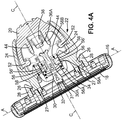
Figure 4A is a longitudinal section of the razor shown inFigure 2A along line IVA-IVA. -
Figure 4B is a longitudinal section of the razor handle shown inFigure 2B along line IVB-IVB. -
Figure 5 is a partial upper view of the razor handle. -
Figure 6 is a longitudinal section of the slide element. -
Figure 7 is a cross-section of the razor shown inFigure 3A along line VII-VII. -
Figure 8A is a longitudinal section of the razor shown inFigure 2A along line VIIIA-VIIIA. -
Figure 8B is a longitudinal section of the razor handle shown inFigure 2B along line VIIIB-VIIIB. -
Figure 1A illustrates arazor 10 comprising arazor handle 12 having ahandle body 14 releasably retaining adisposable shaving cartridge 16. Thehandle body 14 preferably molded out of a plastic material is preferably elongated and extends along a longitudinal direction C-C between afront end 14A and aback end 14B. Besides, the shavingcartridge 16 is provided with one ormore blades 18 each having ablade edge 18A extending parallel to a pivot axis A-A which is perpendicular to the longitudinal direction C-C when theshaving cartridge 16 is connected to therazor handle 12. - The
razor handle 12 further comprises aslide element 20 lockingly connected to the razor handle 12 (as disclosed in details hereafter) and movable between a rest position depicted onFigure 1A and a release position depicted onFigure 1B , and vice versa. In its rest position (Figure 1A ) theslide element 20 may be located backward toward theback end 14B of thehandle body 14, whereas in its release position (Figure 1B ) it may be located forward toward thefront end 14A of thehandle body 14. - The
handle body 14 is terminating in aflexible yoke 22 extending forward for receiving and releasably retaining theshaving cartridge 16 as depicted onFigure 1A . Theyoke 22 may comprises twoflexible arms 24 extending forward from both sides of the longitudinal direction C-C. Theyoke 22 is in its open position, when theslide element 20 is in its rest position; whereas it flexes when theslide element 20 is in its release position. - Each
arm 24 may be provided with connecting means allowing their connection to respective connecting means provided on the shavingcartridge 16. These connecting means are those usually used to pivotably connect a shaving cartridge; they may for instance be journal bearings, shell-bearings, etc. - In the example depicted on the figures, a well-known shell-bearing 26 is provided on the free ends of each of the two
arms 24 extending forward toward the shavingcartridge 16. These shell-bearings 26 can be connected to corresponding rearwardlyprotruding connectors 28 shaped arcuate and provided on the shaving cartridge 16 (as best seen onFigures 1B and2 ). This connection can be of any other known type and is not detailed here. - As best seen on
Figures 2 ,3A and3B , thehandle body 14 may further be provided with anelastic tongue 30 for biasing the shavingcartridge 16 toward a rest position. Thiselastic tongue 30 is molded as a single piece with thehandle body 14 and extends preferably centrally along the longitudinal direction C-C. Thiselastic tongue 30 extends preferably beyond the shell-bearings 26; more precisely thetip 31 the further ahead of theelastic tongue 30 is closer to the pivot axis A-A, than any part of the shell-bearings 26 or of theflanges 27 extending from the shell-bearings 26 laterally in a plan perpendicular to the pivot axis A-A. - Said
elastic tongue 30 may be provided with a twin-cam follower 30A cooperating withcorresponding cam surfaces 32 provided on the shavingcartridge 16 to allow a pivoting of the last in two directions, the rest position corresponding for instance to the midway position. The elastic tongue may however be provided with a single-cam follower (not illustrated) cooperating with a corresponding cam surface provided on the shaving cartridge to allow a pivoting of the last only in one single direction. - The
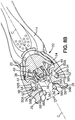
slide element 20 is further provided with apusher 34 to push a shavingcartridge 16 connected to the razor handle 12 away from thehandle body 14. When theslide element 20 slides forward toward the shavingcartridge 16 in its release position, thearms 24 of theyoke 22 flexes preferably inwardly as depicted onFigure 1B leading to the separation of the shell-bearings 26 from the rearwardlyprotruding connectors 28. Meanwhile, thepusher 34 which is also moved forward (provided on the slide element 20) pushes the shavingcartridge 16 away from thehandle body 14. - A spring member is further provided on the razor handle 12 to return the
slide element 20 from the release position (depicted onFigure 1B ) to the rest position (depicted onFigure 1A ). More specifically, this spring member comprises aleaf spring 36 provided on theslide element 20 and bearing against a bearingsurface 38 provided on the handle body 14 (as best seen onFigures 3A ,3B ,4A and4B ). Acentral groove 40 provided on the handle body 14 (as best seen onFigure 5 ) forms a recess receiving theleaf spring 36. Thecentral groove 40 is provided with a rib which forms the bearingsurface 38 and which may have an oblique form. - In any case, this bearing
surface 38 provides a power source for theleaf spring 36 to return theslide element 20 from the release position back to its rest position. - In fact, the
leaf spring 36, more specifically itsfree end 36A is in contact with the bearingsurface 38 in the rest position; when theslide element 20 is pushed forward to its release position, theleaf spring 36 begin to elastically deform and stores energy as long as the force exerted on theslide element 20 occurs (user pushing the slide element 20). This stored energy will be released since the force exerted on theslide element 20 stops and theslide element 20 will naturally slide back to its rest position. - We will now detail how the
slide element 20 is connected to thehandle body 14 and how it can make theyoke 22 flex. - On one side, the
handle body 14 may further be provided with a pair ofelongated tracks 42 located on both sides of thecentral groove 40 and extending along the longitudinal direction C-C (seeFigure 5 ). - On the other side, the
slide element 20 may further be provided with projections 44 (seeFigure 6 ) movable linearly along saidtracks 42 to guide theslide element 20 in sliding movement relative to thehandle body 14. - In order to retain permanently (lockingly) and slidably said
slide element 20 on thehandle body 14, theslide element 20 further compriseslatch elements 46. More precisely, thelatch elements 46 comprise twohooks 46 extending inside thecentral groove 40 on both sides of the longitudinal direction C-C and snapping with correspondingelongated lips 48 provided on thehandle body 14 as best seen onFigure 7 . - The
slide element 20 is snap-fitted on thehandle body 14. Actually, when mounting theslide element 20 on thehandle body 14, thehooks 46 are pressed together in order to be introduced inside thecentral groove 40 and slide along the lateral faces of thelips 48. Meanwhile theslide element 20 is pressed toward the upper face of the handle body until thehooks 46 arrive at the free end 48' of the lips, where the hooks depart from one another and cover the free end 48' of thelips 48 forming a shoulder. - Besides, as best seen on
Figures 4A ,4B ,5 ,8A and8B , each of the twoarms 24 provided on thehandle body 14 may be provided with a cam-follower 50 and the slide element may further comprise twocams 52, the cam-followers 50 being driven by saidcams 52 to flex thearms 24 when theslide element 20 is pushed forward in its release position. - Each of the cam-
followers 50 comprises anon-linear surface 50. More specifically, thecams 52 engage the cam-followers 50 to drive thearms 24. The cam-followers 50 are preferably leaning away from one another from back to front with regard to the longitudinal direction C-C such that when theslide element 20 moves forward in its release position, theyoke 22 flexes inwardly; whereas when theslide element 20 returns rearward in its rest position, theyoke 22 deviates back in its open position. - Besides, to improve the resistance to the shock of the razor handle and to decrease the risk that the
slide element 20 moves inadvertently forward, the surface forming each cam-follower 50 is further provided with abulge 54 providing a resistance to the movement of thecams 52. Actually, it is like each cam-follower 50 was separated in two parts by thebulge 54, afront part 50A corresponding to the forward-most part and aback part 50B corresponding to the rearward-most part. - In the rest position (see
Figures 4A and8A ), thecams 52 are located in theback part 50B and are preferably in contact with or at least near thebulges 54; whereas, in the release position (seeFigures 4B and8B ), thecams 52 are located in thefront part 50A. - To release a shaving
cartridge 16 connected to the handle 12 a user has to overcome the resistance of theslide element 20. Actually, the resistance of thecams 52 abutting against thebulges 54 must be forced by the user. From the rest position (seeFigures 4A and8A ), when a user overcomes this resistance and continues to push forward theslide element 20 in maintaining one of his fingers on thefinger rest area 55 provided on theslide element 20, the cam-followers 50 glide along thecams 52. Since thecams 52 pass thebulges 54 they arrive in thefront part 50A. Meanwhile, thearms 24 become closer to one another in flexing inwardly and the shell-bearings 26 separate from the rearwardly protrudingconnectors 28 on the shavingcartridge 16. Thepusher 34 pushes the shavingcartridge 16 connected to the razor handle 12 away from thehandle body 14 leading to the release of the shavingcartridge 16. - When the user releases the
slide element 20, thanks to the energy stored in theleaf spring 36, theslide element 20 returns back in its rest position and the cam-followers 50 glide along thecams 52. Since thecams 52 pass thebulges 54 they arrive in theback part 50B. Meanwhile, thearms 24 depart from one another and theyoke 22 returns in its open position. - In order to avoid any inadvertently flexion of the
arms 24, the razor handle 12 is further provided with a stop element. As best seen onFigures 4A ,4B ,8A and8B , the stop element comprises preferably twolocators 56 provided on theslide element 20 and aninner surface 58 provided on each of the twoarms 24 against which the correspondinglocator 56 abuts in the rest position. - The two
locators 56 extend toward the bottom part of the razor handle 12 in being lined on both sides of the longitudinal direction C-C. More precisely, the twolocators 56 are located on both sides of theelastic tongue 30. Thelocators 56 are located symmetrically with regard to the longitudinal direction C-C and are separated from each other of a distance D56 taken between the two external (extreme) faces 56' of thelocators 56. - Each
inner surface 58 is like a longitudinal flange extending laterally on both side of the longitudinal direction C-C. Theinner surfaces 58 are located symmetrically with regard to the longitudinal direction C-C and are separated from each other of a distance D58 equal or a little bit greater than the distance D56 separating thelocators 56. Preferably, in the rest position, the relationship between the values of D58 to D56 is comprised between 1 to 10%, more preferably of about 5%. The distance D58 of theinner surfaces 58 is smaller in the release position, where thearms 24 are flexed, than in the rest position. - The length L58, respectively L56, the shape and the location of the
inner surfaces 58, respectively of thelocators 56, is chosen by the skilled person such that theinner surfaces 58 abut against thelocators 56 only when thearms 24 are pressed together while the slide element is in its rest position. - For instance, when the
slide element 20 is in its rest position, thelocators 56 which have preferably a rectangular-shape are completely retracted and substantially located in front of theinner surfaces 58 which are preferably plane; meaning that theforward-most part 56A of thelocators 56 is more or less in front of a part of theinner surfaces 58 as depicted onFigures 4A and8A . When theslide element 20 is in its release position, thelocators 56 are completely extending forward and no part of them is located in front of any part of theinner surfaces 58; meaning that therearward-most part 56B of thelocators 56 is away from theforward-most part 58A of theinner surfaces 58 as depicted onFigures 4B and8B . - In this case, the relationship between the values of L58 to L56 is preferably comprised between 5 to 20%, more preferably of about 10%.
- When the
slide element 20 moves from its rest position to its release position, thelocators 56 slide also forward and move away from the inner surfaces 58. Therefore, since thelocators 56 are no longer in front of theinner surfaces 58, theyoke 22 and more precisely thearms 24 can flex. - In the rest position (see 4A and 8A), the
locators 56 are in abutment or at least in front of theinner surfaces 58 and theyoke 22 is in its open position. When thearms 24 are pressed together (for instance due to a shock during travelling or due to an inadvertently use by a child), thearms 24 cannot flex since theirinner surfaces 58 abut against thelocators 56. Thelocators 56 are sufficiently rigid not to deform such they really prevent any flexion of thearms 24. As a consequence, the shavingcartridge 16 cannot release accidentally. - In the release position (see 4B and 8B), the
locators 56 are away from the inner surfaces 58. Therefore, when thearms 24 are pressed together, thearms 24 can flex since theirinner surfaces 58 do not abut against thelocators 56 and the shavingcartridge 16 can be released. - Actually to release a shaving
cartridge 16 connected to the razor handle 12, theslide element 20 have to be pushed forward, the resistance of thebulges 56 have to be overcome and only after, the release of the shavingcartridge 16 can occur. - Thanks to the invention, the risk of an accidental release of the shaving cartridge from the razor handle which can occur especially when travelling, since the razor and more specifically the actuator can be exposed to several shocks is decreased.
- The
handle body 14 and the slide element are preferably made of a mouldable rigid plastic material. The elasticity of theleaf spring 36 integral with theslide element 20 is preferably due to its specific shape (high ratios of length to width and of length to thickness).
Claims (12)
- A razor handle comprising:- an elongated handle body (14) integral with a flexible yoke (22) for receiving and releasably retaining a shaving cartridge (16),- a slide element (20) cooperating with said yoke (22) and connected to the handle body (14), said slide element being movable relative to the handle body (14) between a rest position, in which the yoke (22) is open and can releasably retain a shaving cartridge (16) received in the yoke (22), and a release position, in which the yoke (22) is flexed and can receive a shaving cartridge (16) or release a shaving cartridge (16) received in the yoke (22), and- a spring member (36) to return said slide element (20) from the release position to the rest position,characterized in that it further comprises a stop element (56, 58) to prevent the yoke (22) from inadvertently flexing when the slide element (20) is in the rest position.
- Razor handle according to the preceding claim, wherein the stop element (56) is provided on the slide element (20).
- Razor handle according to any of the preceding claims, wherein the yoke (22) flexes inwardly when the slide element (20) is in the release position.
- Razor handle according to any of the preceding claims, wherein the yoke (22) comprises two flexible arms (24), each arm (24) being provided with a cam-follower (50) and wherein the slide element (20) further comprises two cams (52), said cam-followers (50) being driven by said cams (52) to flex the arms (24).
- Razor handle according to the preceding claim, wherein each cam-follower (50) comprises a non-linear surface provided with a bulge (54) providing a resistance to the movement of the cams (52).
- Razor handle according to the claim 4 or 5, wherein the stop element (56, 58) comprises two locators (56) and wherein each of the two arms (24) has an inner surface (58) abutting against the corresponding locator (56) while the slide element (20) is in the rest position.
- Razor handle according to any of the claims 4-6, wherein the arms (24) are provided with shell bearings (26) such that the yoke (22) can pivotably receive a shaving cartridge (16).
- Razor handle according to any of the preceding claims, wherein the handle body (14) is further provided with a pair of elongated tracks (42) and wherein the slide element (20) is further provided with projections (44) movable linearly along said tracks (42) to guide the slide element (20), said slide element (20) comprising latch elements (46) to retain permanently and slidably said slide element (20) on the handle body (14).
- Razor handle according to any of the preceding claims, wherein the spring member comprises a leaf spring (36) provided on the slide element (20) and bearing against a bearing surface (38) provided on the handle body (14).
- Razor handle according to any of the preceding claims, wherein the handle body (14) is further provided with an elastic tongue (30) for biasing a shaving cartridge (16) toward a rest position.
- Razor handle according to any of the preceding claims, wherein the slide element (20) is further provided with a pusher (34) to push a shaving cartridge (16) away from the handle body (14).
- A razor comprising a handle according to any of the preceding claims and a razor cartridge (16) connected to the razor handle (12).
Priority Applications (1)
| Application Number | Priority Date | Filing Date | Title |
|---|---|---|---|
| PL08804976T PL2334475T3 (en) | 2008-10-01 | 2008-10-01 | Razor handles to be realeasably connected to shaving cartridges and razors including such handles. |
Applications Claiming Priority (1)
| Application Number | Priority Date | Filing Date | Title |
|---|---|---|---|
| PCT/EP2008/063187 WO2010037418A1 (en) | 2008-10-01 | 2008-10-01 | Razor handles to be realeasably connected to shaving cartridges and razors including such handles. |
Publications (2)
| Publication Number | Publication Date |
|---|---|
| EP2334475A1 EP2334475A1 (en) | 2011-06-22 |
| EP2334475B1 true EP2334475B1 (en) | 2020-02-12 |
Family
ID=40765562
Family Applications (1)
| Application Number | Title | Priority Date | Filing Date |
|---|---|---|---|
| EP08804976.2A Active EP2334475B1 (en) | 2008-10-01 | 2008-10-01 | Razor handles to be realeasably connected to shaving cartridges and razors including such handles. |
Country Status (13)
| Country | Link |
|---|---|
| US (1) | US8732965B2 (en) |
| EP (1) | EP2334475B1 (en) |
| JP (1) | JP5497046B2 (en) |
| KR (1) | KR101486932B1 (en) |
| CN (1) | CN102202840B (en) |
| BR (1) | BRPI0823103B1 (en) |
| CA (1) | CA2737995C (en) |
| EG (1) | EG26963A (en) |
| MX (1) | MX2011003463A (en) |
| PL (1) | PL2334475T3 (en) |
| RU (1) | RU2486050C2 (en) |
| WO (1) | WO2010037418A1 (en) |
| ZA (1) | ZA201102037B (en) |
Families Citing this family (47)
| Publication number | Priority date | Publication date | Assignee | Title |
|---|---|---|---|---|
| CN102015718B (en) * | 2008-04-24 | 2014-12-10 | Abbvie德国有限责任两合公司 | 1- (7-(hexahydropyrrolo [3, 4-C] pyrrol-2 (1H) -yl) quin0lin-4-yl) -3- (pyrazin-2-yl) urea derivatives and related compounds as glycogen synthase kinase 3 (GSK-3) |
| US20100313426A1 (en) * | 2009-06-12 | 2010-12-16 | Terence Gordon Royle | Safety razor with pivot and rotation |
| US8474144B2 (en) * | 2009-08-12 | 2013-07-02 | The Gillette Company | Safety razor with rotational movement and locking button |
| US8745883B2 (en) | 2010-09-29 | 2014-06-10 | The Gillette Company | Razor handle with a rotatable portion |
| US8745882B2 (en) | 2010-09-29 | 2014-06-10 | The Gillette Company | Flexible and separable portion of a razor handle |
| CN102452088B (en) * | 2010-10-28 | 2015-07-01 | 吉列公司 | Hair removing device with blade holder holding covering part |
| US8978258B2 (en) | 2011-04-05 | 2015-03-17 | The Gillette Company | Razor handle with a rotatable portion |
| US8938885B2 (en) | 2012-05-01 | 2015-01-27 | The Gillette Company | Razor handle with a rotatable portion |
| CN104684698B (en) * | 2012-12-11 | 2016-04-20 | 任向荣 | The handle of shaver and shaver |
| US9623575B2 (en) * | 2012-12-18 | 2017-04-18 | Shavelogic, Inc. | Shaving systems |
| JP6113301B2 (en) * | 2012-12-21 | 2017-04-12 | ビック・バイオレクス・エス・エー | shaver |
| CA2894453A1 (en) * | 2012-12-21 | 2014-06-26 | Bic-Violex Sa | Shaver |
| CN104884212B (en) * | 2012-12-21 | 2018-05-29 | 比克-维尔莱克 | Shaver with the replaceable knife rest and knife rest for the shaver, head and handle combination |
| WO2015158382A1 (en) | 2014-04-16 | 2015-10-22 | Bic-Violex Sa | Handles for shavers to be releasably connected to shaving cartridges |
| JP6496824B2 (en) * | 2014-12-05 | 2019-04-10 | ビック・バイオレクス・エス・エー | Shaver handle with locking and release mechanism for engaging and disengaging with razor cartridge |
| US10131063B2 (en) | 2015-09-29 | 2018-11-20 | The Gillette Company Llc | Adapter for attaching a razor cartridge to a razor handle |
| US20170087733A1 (en) * | 2015-09-29 | 2017-03-30 | The Gillette Company | Kit Comprising A Razor Cartridge And An Adapter |
| BR112018068899A2 (en) | 2016-03-18 | 2019-01-22 | Personal Care Marketing And Res Inc | razor blade cartridge |
| USD765912S1 (en) | 2016-03-23 | 2016-09-06 | Phan Thi Minh Vinh | Razor handle |
| EP3439838B1 (en) * | 2016-04-05 | 2020-05-27 | BIC-Violex S.A. | A shaver's handle with a lock and release mechanism for engaging and disengaging a razor cartridge |
| US9993931B1 (en) | 2016-11-23 | 2018-06-12 | Personal Care Marketing And Research, Inc. | Razor docking and pivot |
| EP3348363B1 (en) * | 2017-01-17 | 2019-07-24 | BIC-Violex S.A. | A shaving handle system for holding a cartridge pivotable about two axes |
| EP3348364B1 (en) | 2017-01-17 | 2020-04-15 | BIC-Violex S.A. | A handle for a shaver enabling rotational movement of a cartridge |
| KR20190103218A (en) | 2017-01-17 | 2019-09-04 | 빅-비올렉스 에스아 | Connector for wet shaving cartridge that can pivot about 2 axes |
| EP3372360A1 (en) | 2017-03-10 | 2018-09-12 | BIC-Violex S.A. | Method of manufacturing a shaver |
| MX2019009376A (en) | 2017-03-10 | 2019-09-23 | Bic Violex Sa | Shaver handle, shaver including such a handle and method of manufacturing the same. |
| USD802842S1 (en) | 2017-03-15 | 2017-11-14 | Vu Phan Quang Ngo | Safety razor handle |
| EP3398738B1 (en) | 2017-05-05 | 2020-03-11 | BIC Violex S.A. | Razor handle |
| USD815776S1 (en) | 2017-10-08 | 2018-04-17 | Vu Phan Quang Ngo | Safety razor |
| EP3774230A1 (en) | 2018-03-30 | 2021-02-17 | The Gillette Company LLC | Razor handle with a pivoting portion |
| JP7090727B2 (en) | 2018-03-30 | 2022-06-24 | ザ ジレット カンパニー リミテッド ライアビリティ カンパニー | Razor handle with pivot part |
| CN111867795B (en) | 2018-03-30 | 2022-03-18 | 吉列有限责任公司 | Razor handle |
| AU2019243158B2 (en) * | 2018-03-30 | 2022-07-07 | The Gillette Company Llc | Shaving razor cartridge |
| US11123888B2 (en) | 2018-03-30 | 2021-09-21 | The Gillette Company Llc | Razor handle with a pivoting portion |
| USD874061S1 (en) | 2018-03-30 | 2020-01-28 | The Gillette Company Llc | Shaving razor cartridge |
| US11577417B2 (en) | 2018-03-30 | 2023-02-14 | The Gillette Company Llc | Razor handle with a pivoting portion |
| CN109015771A (en) * | 2018-08-23 | 2018-12-18 | 方盛 | A kind of shaver |
| USD884971S1 (en) | 2019-02-27 | 2020-05-19 | Pcmr International Ltd | Razor cartridge |
| USD884970S1 (en) | 2019-02-27 | 2020-05-19 | PCMR International Ltd. | Razor cartridge guard |
| USD884969S1 (en) | 2019-02-27 | 2020-05-19 | Pcmr International Ltd | Combined razor cartridge guard and docking |
| US11161263B2 (en) | 2019-08-22 | 2021-11-02 | Harry's, Inc. | Razor cartridge connection and handle |
| EP3888861A1 (en) * | 2020-03-30 | 2021-10-06 | Bic Violex S.A. | Coupling mechanism |
| US11000960B1 (en) | 2020-11-16 | 2021-05-11 | Personal Care Marketing And Research, Inc. | Razor exposure |
| KR20220155119A (en) * | 2021-05-14 | 2022-11-22 | 주식회사 도루코 | Razor Cartridge And Razor Assembly Including the Same |
| US20220379509A1 (en) * | 2021-05-25 | 2022-12-01 | The Gillette Company Llc | Integrated spring element |
| CN216658034U (en) * | 2021-11-03 | 2022-06-03 | 深圳诺泰科电子有限公司 | Shaver |
| EP4335603A1 (en) * | 2022-09-12 | 2024-03-13 | BIC Violex Single Member S.A. | Razor connector |
Family Cites Families (13)
| Publication number | Priority date | Publication date | Assignee | Title |
|---|---|---|---|---|
| NL176237C (en) | 1981-03-02 | 1985-03-18 | Warner Lambert Co | SHAVER. |
| US4797998A (en) * | 1986-12-08 | 1989-01-17 | Warner-Lambert Company | Lockable pivotable razor |
| AU638974B2 (en) * | 1989-06-05 | 1993-07-15 | Warner-Lambert Company | Razor mechanism |
| US5784790A (en) * | 1996-04-10 | 1998-07-28 | The Gillette Company | Shaving razor and method |
| US5956851A (en) * | 1996-04-10 | 1999-09-28 | The Gillette Company | Shaving system including handle and replaceable cartridges |
| US5953824A (en) * | 1997-09-23 | 1999-09-21 | Warner-Lambert Company | Razors providing pivoting and swivelling razor head support |
| US7200942B2 (en) * | 2001-03-28 | 2007-04-10 | Eveready Battery Company, Inc. | Safety razor with pivot point shift from center to guard-bar under applied load |
| WO2005090016A1 (en) * | 2004-03-15 | 2005-09-29 | Bic-Violex Sa | Razor having two silideable shaving heads |
| WO2006027018A1 (en) * | 2004-09-07 | 2006-03-16 | Bic-Violex Sa | Razor handle and shaver including such a handle |
| EP1863618B1 (en) * | 2005-02-03 | 2008-10-08 | BIC Violex S.A. | Razor handle having ergonomic ribbed sides |
| US8230600B2 (en) * | 2007-09-17 | 2012-07-31 | The Gillette Company | Cartridge detachment sensor |
| US8205344B2 (en) * | 2008-08-20 | 2012-06-26 | The Gillette Company | Safety razor having pivotable blade unit |
| US8209868B2 (en) * | 2009-07-27 | 2012-07-03 | The Gillette Company | Device with an illuminated button assembly |
-
2008
- 2008-10-01 JP JP2011529451A patent/JP5497046B2/en active Active
- 2008-10-01 PL PL08804976T patent/PL2334475T3/en unknown
- 2008-10-01 US US13/121,336 patent/US8732965B2/en active Active
- 2008-10-01 CA CA2737995A patent/CA2737995C/en active Active
- 2008-10-01 BR BRPI0823103-6A patent/BRPI0823103B1/en active IP Right Grant
- 2008-10-01 EP EP08804976.2A patent/EP2334475B1/en active Active
- 2008-10-01 RU RU2011115979/02A patent/RU2486050C2/en active
- 2008-10-01 CN CN200880131698.3A patent/CN102202840B/en active Active
- 2008-10-01 WO PCT/EP2008/063187 patent/WO2010037418A1/en active Application Filing
- 2008-10-01 MX MX2011003463A patent/MX2011003463A/en active IP Right Grant
- 2008-10-01 KR KR1020117010113A patent/KR101486932B1/en active IP Right Grant
-
2011
- 2011-03-17 ZA ZA2011/02037A patent/ZA201102037B/en unknown
- 2011-03-29 EG EG2011030485A patent/EG26963A/en active
Non-Patent Citations (1)
| Title |
|---|
| None * |
Also Published As
| Publication number | Publication date |
|---|---|
| US20110239475A1 (en) | 2011-10-06 |
| EG26963A (en) | 2015-02-08 |
| ZA201102037B (en) | 2012-05-30 |
| MX2011003463A (en) | 2011-08-03 |
| CN102202840A (en) | 2011-09-28 |
| RU2011115979A (en) | 2012-11-10 |
| PL2334475T3 (en) | 2020-05-18 |
| WO2010037418A1 (en) | 2010-04-08 |
| KR101486932B1 (en) | 2015-01-27 |
| CA2737995A1 (en) | 2010-04-08 |
| BRPI0823103A2 (en) | 2015-06-16 |
| CA2737995C (en) | 2015-04-07 |
| BRPI0823103B1 (en) | 2021-03-09 |
| KR20110093776A (en) | 2011-08-18 |
| CN102202840B (en) | 2014-10-29 |
| EP2334475A1 (en) | 2011-06-22 |
| US8732965B2 (en) | 2014-05-27 |
| RU2486050C2 (en) | 2013-06-27 |
| JP5497046B2 (en) | 2014-05-21 |
| JP2012504434A (en) | 2012-02-23 |
Similar Documents
| Publication | Publication Date | Title |
|---|---|---|
| EP2334475B1 (en) | Razor handles to be realeasably connected to shaving cartridges and razors including such handles. | |
| EP3619009B1 (en) | Razor handle | |
| EP2753461B1 (en) | Razors and razor handles | |
| US6560881B2 (en) | Shaving razor with pivoting blade carrier and replaceable blade cartridge therefor | |
| EP2180985B1 (en) | Razor with blade unit biasing member | |
| US11325270B2 (en) | Metal spring return and method | |
| EP2536539B1 (en) | Shaving razor adapter attaching a shaving razor cartridge to a shaving razor handle | |
| EP2387489B1 (en) | Docking mechanism for shaving razors and cartridges | |
| KR20160146834A (en) | Handles for shavers to be releasably connected to shaving cartridges | |
| MX2010011155A (en) | Razor handle for a retractable shaving cartridge and a razor comprising such a razor handle. | |
| KR20150099587A (en) | Shaver | |
| WO2014094905A1 (en) | Shaver with interchangeable cartridge, cartridge and head and handle assembly for such shaver | |
| WO2017174120A1 (en) | A shaver's handle with a lock and release mechanism for engaging and disengaging a razor cartridge | |
| CN110520263B (en) | Razor handle | |
| GB2226973A (en) | Safety razor |
Legal Events
| Date | Code | Title | Description |
|---|---|---|---|
| PUAI | Public reference made under article 153(3) epc to a published international application that has entered the european phase |
Free format text: ORIGINAL CODE: 0009012 |
|
| 17P | Request for examination filed |
Effective date: 20110401 |
|
| AK | Designated contracting states |
Kind code of ref document: A1 Designated state(s): AT BE BG CH CY CZ DE DK EE ES FI FR GB GR HR HU IE IS IT LI LT LU LV MC MT NL NO PL PT RO SE SI SK TR |
|
| AX | Request for extension of the european patent |
Extension state: AL BA MK RS |
|
| RIN1 | Information on inventor provided before grant (corrected) |
Inventor name: BOZIKIS, IOANNIS Inventor name: GRATSIAS, SPIROS Inventor name: EFTHIMIADIS, DIMITRIS |
|
| DAX | Request for extension of the european patent (deleted) | ||
| STAA | Information on the status of an ep patent application or granted ep patent |
Free format text: STATUS: EXAMINATION IS IN PROGRESS |
|
| 17Q | First examination report despatched |
Effective date: 20170926 |
|
| GRAP | Despatch of communication of intention to grant a patent |
Free format text: ORIGINAL CODE: EPIDOSNIGR1 |
|
| STAA | Information on the status of an ep patent application or granted ep patent |
Free format text: STATUS: GRANT OF PATENT IS INTENDED |
|
| INTG | Intention to grant announced |
Effective date: 20190902 |
|
| GRAS | Grant fee paid |
Free format text: ORIGINAL CODE: EPIDOSNIGR3 |
|
| GRAA | (expected) grant |
Free format text: ORIGINAL CODE: 0009210 |
|
| STAA | Information on the status of an ep patent application or granted ep patent |
Free format text: STATUS: THE PATENT HAS BEEN GRANTED |
|
| AK | Designated contracting states |
Kind code of ref document: B1 Designated state(s): AT BE BG CH CY CZ DE DK EE ES FI FR GB GR HR HU IE IS IT LI LT LU LV MC MT NL NO PL PT RO SE SI SK TR |
|
| REG | Reference to a national code |
Ref country code: GB Ref legal event code: FG4D |
|
| REG | Reference to a national code |
Ref country code: CH Ref legal event code: EP |
|
| REG | Reference to a national code |
Ref country code: AT Ref legal event code: REF Ref document number: 1231490 Country of ref document: AT Kind code of ref document: T Effective date: 20200215 |
|
| REG | Reference to a national code |
Ref country code: IE Ref legal event code: FG4D |
|
| REG | Reference to a national code |
Ref country code: DE Ref legal event code: R096 Ref document number: 602008062119 Country of ref document: DE |
|
| PG25 | Lapsed in a contracting state [announced via postgrant information from national office to epo] |
Ref country code: FI Free format text: LAPSE BECAUSE OF FAILURE TO SUBMIT A TRANSLATION OF THE DESCRIPTION OR TO PAY THE FEE WITHIN THE PRESCRIBED TIME-LIMIT Effective date: 20200212 Ref country code: NO Free format text: LAPSE BECAUSE OF FAILURE TO SUBMIT A TRANSLATION OF THE DESCRIPTION OR TO PAY THE FEE WITHIN THE PRESCRIBED TIME-LIMIT Effective date: 20200512 |
|
| REG | Reference to a national code |
Ref country code: LT Ref legal event code: MG4D |
|
| REG | Reference to a national code |
Ref country code: NL Ref legal event code: MP Effective date: 20200212 |
|
| PG25 | Lapsed in a contracting state [announced via postgrant information from national office to epo] |
Ref country code: GR Free format text: LAPSE BECAUSE OF FAILURE TO SUBMIT A TRANSLATION OF THE DESCRIPTION OR TO PAY THE FEE WITHIN THE PRESCRIBED TIME-LIMIT Effective date: 20200513 Ref country code: BG Free format text: LAPSE BECAUSE OF FAILURE TO SUBMIT A TRANSLATION OF THE DESCRIPTION OR TO PAY THE FEE WITHIN THE PRESCRIBED TIME-LIMIT Effective date: 20200512 Ref country code: HR Free format text: LAPSE BECAUSE OF FAILURE TO SUBMIT A TRANSLATION OF THE DESCRIPTION OR TO PAY THE FEE WITHIN THE PRESCRIBED TIME-LIMIT Effective date: 20200212 Ref country code: SE Free format text: LAPSE BECAUSE OF FAILURE TO SUBMIT A TRANSLATION OF THE DESCRIPTION OR TO PAY THE FEE WITHIN THE PRESCRIBED TIME-LIMIT Effective date: 20200212 Ref country code: LV Free format text: LAPSE BECAUSE OF FAILURE TO SUBMIT A TRANSLATION OF THE DESCRIPTION OR TO PAY THE FEE WITHIN THE PRESCRIBED TIME-LIMIT Effective date: 20200212 Ref country code: IS Free format text: LAPSE BECAUSE OF FAILURE TO SUBMIT A TRANSLATION OF THE DESCRIPTION OR TO PAY THE FEE WITHIN THE PRESCRIBED TIME-LIMIT Effective date: 20200612 |
|
| PG25 | Lapsed in a contracting state [announced via postgrant information from national office to epo] |
Ref country code: NL Free format text: LAPSE BECAUSE OF FAILURE TO SUBMIT A TRANSLATION OF THE DESCRIPTION OR TO PAY THE FEE WITHIN THE PRESCRIBED TIME-LIMIT Effective date: 20200212 |
|
| PG25 | Lapsed in a contracting state [announced via postgrant information from national office to epo] |
Ref country code: ES Free format text: LAPSE BECAUSE OF FAILURE TO SUBMIT A TRANSLATION OF THE DESCRIPTION OR TO PAY THE FEE WITHIN THE PRESCRIBED TIME-LIMIT Effective date: 20200212 Ref country code: DK Free format text: LAPSE BECAUSE OF FAILURE TO SUBMIT A TRANSLATION OF THE DESCRIPTION OR TO PAY THE FEE WITHIN THE PRESCRIBED TIME-LIMIT Effective date: 20200212 Ref country code: EE Free format text: LAPSE BECAUSE OF FAILURE TO SUBMIT A TRANSLATION OF THE DESCRIPTION OR TO PAY THE FEE WITHIN THE PRESCRIBED TIME-LIMIT Effective date: 20200212 Ref country code: RO Free format text: LAPSE BECAUSE OF FAILURE TO SUBMIT A TRANSLATION OF THE DESCRIPTION OR TO PAY THE FEE WITHIN THE PRESCRIBED TIME-LIMIT Effective date: 20200212 Ref country code: SK Free format text: LAPSE BECAUSE OF FAILURE TO SUBMIT A TRANSLATION OF THE DESCRIPTION OR TO PAY THE FEE WITHIN THE PRESCRIBED TIME-LIMIT Effective date: 20200212 Ref country code: CZ Free format text: LAPSE BECAUSE OF FAILURE TO SUBMIT A TRANSLATION OF THE DESCRIPTION OR TO PAY THE FEE WITHIN THE PRESCRIBED TIME-LIMIT Effective date: 20200212 Ref country code: LT Free format text: LAPSE BECAUSE OF FAILURE TO SUBMIT A TRANSLATION OF THE DESCRIPTION OR TO PAY THE FEE WITHIN THE PRESCRIBED TIME-LIMIT Effective date: 20200212 Ref country code: PT Free format text: LAPSE BECAUSE OF FAILURE TO SUBMIT A TRANSLATION OF THE DESCRIPTION OR TO PAY THE FEE WITHIN THE PRESCRIBED TIME-LIMIT Effective date: 20200705 |
|
| REG | Reference to a national code |
Ref country code: DE Ref legal event code: R097 Ref document number: 602008062119 Country of ref document: DE |
|
| REG | Reference to a national code |
Ref country code: AT Ref legal event code: MK05 Ref document number: 1231490 Country of ref document: AT Kind code of ref document: T Effective date: 20200212 |
|
| PLBE | No opposition filed within time limit |
Free format text: ORIGINAL CODE: 0009261 |
|
| STAA | Information on the status of an ep patent application or granted ep patent |
Free format text: STATUS: NO OPPOSITION FILED WITHIN TIME LIMIT |
|
| 26N | No opposition filed |
Effective date: 20201113 |
|
| PG25 | Lapsed in a contracting state [announced via postgrant information from national office to epo] |
Ref country code: AT Free format text: LAPSE BECAUSE OF FAILURE TO SUBMIT A TRANSLATION OF THE DESCRIPTION OR TO PAY THE FEE WITHIN THE PRESCRIBED TIME-LIMIT Effective date: 20200212 |
|
| PG25 | Lapsed in a contracting state [announced via postgrant information from national office to epo] |
Ref country code: SI Free format text: LAPSE BECAUSE OF FAILURE TO SUBMIT A TRANSLATION OF THE DESCRIPTION OR TO PAY THE FEE WITHIN THE PRESCRIBED TIME-LIMIT Effective date: 20200212 |
|
| REG | Reference to a national code |
Ref country code: CH Ref legal event code: PL |
|
| PG25 | Lapsed in a contracting state [announced via postgrant information from national office to epo] |
Ref country code: LU Free format text: LAPSE BECAUSE OF NON-PAYMENT OF DUE FEES Effective date: 20201001 Ref country code: MC Free format text: LAPSE BECAUSE OF FAILURE TO SUBMIT A TRANSLATION OF THE DESCRIPTION OR TO PAY THE FEE WITHIN THE PRESCRIBED TIME-LIMIT Effective date: 20200212 |
|
| REG | Reference to a national code |
Ref country code: BE Ref legal event code: MM Effective date: 20201031 |
|
| PG25 | Lapsed in a contracting state [announced via postgrant information from national office to epo] |
Ref country code: LI Free format text: LAPSE BECAUSE OF NON-PAYMENT OF DUE FEES Effective date: 20201031 Ref country code: CH Free format text: LAPSE BECAUSE OF NON-PAYMENT OF DUE FEES Effective date: 20201031 Ref country code: BE Free format text: LAPSE BECAUSE OF NON-PAYMENT OF DUE FEES Effective date: 20201031 |
|
| PG25 | Lapsed in a contracting state [announced via postgrant information from national office to epo] |
Ref country code: IE Free format text: LAPSE BECAUSE OF NON-PAYMENT OF DUE FEES Effective date: 20201001 |
|
| PG25 | Lapsed in a contracting state [announced via postgrant information from national office to epo] |
Ref country code: TR Free format text: LAPSE BECAUSE OF FAILURE TO SUBMIT A TRANSLATION OF THE DESCRIPTION OR TO PAY THE FEE WITHIN THE PRESCRIBED TIME-LIMIT Effective date: 20200212 Ref country code: MT Free format text: LAPSE BECAUSE OF FAILURE TO SUBMIT A TRANSLATION OF THE DESCRIPTION OR TO PAY THE FEE WITHIN THE PRESCRIBED TIME-LIMIT Effective date: 20200212 Ref country code: CY Free format text: LAPSE BECAUSE OF FAILURE TO SUBMIT A TRANSLATION OF THE DESCRIPTION OR TO PAY THE FEE WITHIN THE PRESCRIBED TIME-LIMIT Effective date: 20200212 |
|
| P01 | Opt-out of the competence of the unified patent court (upc) registered |
Effective date: 20230530 |
|
| PGFP | Annual fee paid to national office [announced via postgrant information from national office to epo] |
Ref country code: IT Payment date: 20230920 Year of fee payment: 16 Ref country code: GB Payment date: 20230920 Year of fee payment: 16 |
|
| PGFP | Annual fee paid to national office [announced via postgrant information from national office to epo] |
Ref country code: PL Payment date: 20230920 Year of fee payment: 16 Ref country code: FR Payment date: 20230920 Year of fee payment: 16 |
|
| PGFP | Annual fee paid to national office [announced via postgrant information from national office to epo] |
Ref country code: DE Payment date: 20230920 Year of fee payment: 16 |