EP2334140A1 - Clamping claw - Google Patents
Clamping claw Download PDFInfo
- Publication number
- EP2334140A1 EP2334140A1 EP09015395A EP09015395A EP2334140A1 EP 2334140 A1 EP2334140 A1 EP 2334140A1 EP 09015395 A EP09015395 A EP 09015395A EP 09015395 A EP09015395 A EP 09015395A EP 2334140 A1 EP2334140 A1 EP 2334140A1
- Authority
- EP
- European Patent Office
- Prior art keywords
- base element
- clamping claw
- sections
- carrier plate
- appliance
- Prior art date
- Legal status (The legal status is an assumption and is not a legal conclusion. Google has not performed a legal analysis and makes no representation as to the accuracy of the status listed.)
- Withdrawn
Links
Images
Classifications
-
- H—ELECTRICITY
- H05—ELECTRIC TECHNIQUES NOT OTHERWISE PROVIDED FOR
- H05B—ELECTRIC HEATING; ELECTRIC LIGHT SOURCES NOT OTHERWISE PROVIDED FOR; CIRCUIT ARRANGEMENTS FOR ELECTRIC LIGHT SOURCES, IN GENERAL
- H05B3/00—Ohmic-resistance heating
- H05B3/68—Heating arrangements specially adapted for cooking plates or analogous hot-plates
- H05B3/74—Non-metallic plates, e.g. vitroceramic, ceramic or glassceramic hobs, also including power or control circuits
-
- F—MECHANICAL ENGINEERING; LIGHTING; HEATING; WEAPONS; BLASTING
- F24—HEATING; RANGES; VENTILATING
- F24C—DOMESTIC STOVES OR RANGES ; DETAILS OF DOMESTIC STOVES OR RANGES, OF GENERAL APPLICATION
- F24C15/00—Details
- F24C15/10—Tops, e.g. hot plates; Rings
- F24C15/108—Mounting of hot plate on worktop
Definitions
- the present invention relates to a clamping claw designed for fixing an appliance, which is inserted in an assembly opening of a carrier plate and rests on the top side of the carrier plate, such as a ceramic stove top or the like.
- a ceramic stove top is normally installed by inserting it into an assembly opening of a carrier plate, e.g. a kitchen counter-top, from above, such that a rim provided at the upper side of the stove top rests on the top side of the carrier plate.
- a carrier plate e.g. a kitchen counter-top
- clamping claws are provided, which pull the stove top downwards at high forces. Since the forces of today's clamping claws neither can be limited nor varied there is an imminent danger that the stove top and/or the carrier plate and/or the clamping claws are damaged.
- the present invention provides a clamping claw of the above-mentioned kind comprising a base element fixable to a lower portion of the appliance; at least one spring element, which is maintained at the base element and rests on the bottom side of the carrier plate in the assembled state of the clamping claw; and tensioning means being formed in such a manner that they tension the spring element along a clamp travel of pre-defined limited length.
- the clamp travel of the spring element has a pre-defined limited length
- the maximum clamping force creatable by the clamping claw in regard to a special intended application is limited. Accordingly, a damaging of the appliance and/or the carrier plate and/or the clamping claw itself can be prevented by properly limiting the maximum clamping force of the clamping claw with regard to the intended application by limiting the clamp travel of the spring element.
- the tensioning means comprises an actuating element and oppositely arranged base element sections, which are relatively movable with respect to each other by operating the actuating element, whereas the spring element is arranged between the base element sections and rests on one of the base element sections in the assembled state of the clamping claw.
- the clamp travel of the spring element is essentially defined by the distance between the oppositely arranged base element sections at the maintaining position of the spring element.
- the actuating element is a screw, which extends through the oppositely arranged base element sections and causes, when operated, a relative movement between the base element sections and thus, in the assembled state of the clamping claw, a tensioning of the spring element resting on one of the base element sections as well as on the bottom side of the carrier plate.
- a screw leads to an inexpensive and simple design of the clamping claw and is easy to handle by a user.
- the base element can be formed as a one-piece component and has a longish elastically deformable ring shape, wherein the actuating element extends through the oppositely arranged longish base element sections.
- one of the base element sections is provided with at least one guiding projection facing towards the other base element section, and the other base element is provided with a corresponding guiding opening receiving the guiding projection during a relative movement between the base element sections. Accordingly, a guided and uniform movement between the base element sections is ensured.
- spacers are provided, which project from the base element and are spaced apart from the actuating element, wherein the spacers are preferably made integral with the base element.
- Such spacers rest on a lower portion of the appliance in the assembled state of the clamping claw and promote a uniform deformation of the base element upon the actuation of the actuating element.
- the base element comprises latching means, in particular latching hooks, for fixing the base element to the appliance, wherein the latching means are preferably made integral with the base element.
- latching hooks promote the ease of assembly.
- the base element is preferably made of plastic material.
- the spring element essentially has a Z-form.
- the spring element preferably is made of spring steel or of an elastic plastic material having similar characteristics.
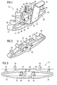
- FIG. 1 shows a clamping claw 10 according to an embodiment of the present invention.
- the clamping claw 10 is designed for fixing an appliance, such as a ceramic stove top or the like, which is inserted in an assembly opening of a carrier plate and rests on the top side of a carrier plate.
- the clamping claw 10 comprises a base element 12 fixable to a lower portion of the appliance, a spring element 14, which is maintained at the base element 12 and rests on the bottom side of the carrier plate in the assembled state of the clamping claw 10, and a tensioning means 16 being formed in such a manner that it tensions the spring element 14 along a clamp travel D of pre-defined limited length.
- the base element 12 is formed as a one-piece-component made of plastic material and has a longish elastically deformable ring shape.
- the ring shape is defined by two base element sections 18 and 20, which are oppositely arranged and extend in parallel, and by two essentially V-shaped base element connecting sections 22 and 24, which connect the base element sections 18 and 20.
- the upper base element section 18 is formed with a contact surface 26 at its outer side, which rests on an appliance to be fixed in the assembled state of the clamping claw 10.
- the base element connecting sections 22 and 24 are each provided with latching hooks 28 and 30 which are arranged next to the upper base element section 18 and extend upwards, such that they project beyond the contact surface 26 of the upper base element section 18.
- the base element connecting sections 22 and 24 are both formed with upwardly extending spacers 32 and 34 on their upper sides.
- through holes 36 and 38 are provided, which are aligned with each other and receive the tensioning means 16.
- the lower base element section 20 is formed with a guiding projection 40, 42 facing towards the upper base element section 18.
- the upper base element section 18 is provided with two corresponding guiding openings 44 and 46, which are aligned with and receive the guiding projection 40 and 42, respectively, during a relative movement between the base element sections 18 and 20.
- the spring element 14 is a one-piece component made of spring steel and essentially has a Z-shape, which is defined by a mounting section 48, a center section 50 and a supporting section 52.
- the mounting section 48 contacts the lower base element section 20 of the base element 12 and extends in parallel thereto, the center section 50 extends upwards from the mounting section 48 beyond the latching hooks 28 and 30 of the base element 12, and the joining supporting section 52 extends slightly downwards.
- the mounting section 48 of the spring element 14 is provided with a through hole 54 for receiving the tensioning means 16.
- the tensioning means 16 is formed by a conventional screw 56 having a thread 58 and the two base element sections 18 and 20.
- the clamping claw 10 In order to fix an appliance, which is inserted in an assembly opening of a carrier plate and rests on the top side of the carrier plate, such as a ceramic stove top or the like, by means of a clamping claw 10, the clamping claw 10 is attached to the bottom wall of the appliance inclose proximity to the bottom wall edge by inserting the latching hooks 28 and 30 of the base element 12 into corresponding latching openings formed in the bottom surface of the appliance.
- the contact surface 26 rests on the bottom wall of the appliance, and the spring element 14 upwardly projects from the bottom wall of the appliance towards the bottom wall of the carrier plate and rests thereon.
- the screw 56 is screwed in a corresponding threaded bore of the appliance.
- the lower base element section Upon further tightening of the screw 56, the lower base element section is moved towards the upper base element section, such that the spring element 14 is tensioned in order to eliminate a clearance present between the appliance and the top side of the carrier plate. During this movement the spacers 32 and 34 come into contact with the bottom wall of the appliance and ensure a uniform deformation of the base element 12 while further tightening the screw 56.
- the maximum clamping force which can be created in this manner, is limited by the distance D between the upper base element section 18 and lower base element section 20 essentially representing the clamp travel D of the spring element 14.
- the maximum clamping force creatable by means of the clamping claw 10 can be varied by using a stronger or weaker spring element 14 or by providing several base elements 12 whose upper and lower base element sections 18 and 20 defined clamp travels D of different lengths.
- the clamping force of the clamping claw 10 can be adapted to different applications, e.g. carrier plates and/or appliances of different heights or the like.
Landscapes
- Engineering & Computer Science (AREA)
- Chemical & Material Sciences (AREA)
- Ceramic Engineering (AREA)
- Combustion & Propulsion (AREA)
- Mechanical Engineering (AREA)
- General Engineering & Computer Science (AREA)
- Clamps And Clips (AREA)
Abstract
Description
- The present invention relates to a clamping claw designed for fixing an appliance, which is inserted in an assembly opening of a carrier plate and rests on the top side of the carrier plate, such as a ceramic stove top or the like.
- A ceramic stove top is normally installed by inserting it into an assembly opening of a carrier plate, e.g. a kitchen counter-top, from above, such that a rim provided at the upper side of the stove top rests on the top side of the carrier plate. In order to reduce the clearance between the appliance and the carrier plate, clamping claws are provided, which pull the stove top downwards at high forces. Since the forces of today's clamping claws neither can be limited nor varied there is an imminent danger that the stove top and/or the carrier plate and/or the clamping claws are damaged.
- Starting from this prior art technology it is an object of the present invention to provide a clamping claw of the above mentioned kind, which ensures a defined clamping force, that is variable depending on the intended field of application.
- In order to solve this object the present invention provides a clamping claw of the above-mentioned kind comprising a base element fixable to a lower portion of the appliance; at least one spring element, which is maintained at the base element and rests on the bottom side of the carrier plate in the assembled state of the clamping claw; and tensioning means being formed in such a manner that they tension the spring element along a clamp travel of pre-defined limited length.
- Due to the fact that the clamp travel of the spring element has a pre-defined limited length, also the maximum clamping force creatable by the clamping claw in regard to a special intended application is limited. Accordingly, a damaging of the appliance and/or the carrier plate and/or the clamping claw itself can be prevented by properly limiting the maximum clamping force of the clamping claw with regard to the intended application by limiting the clamp travel of the spring element.
- According to an embodiment of the present invention the tensioning means comprises an actuating element and oppositely arranged base element sections, which are relatively movable with respect to each other by operating the actuating element, whereas the spring element is arranged between the base element sections and rests on one of the base element sections in the assembled state of the clamping claw. Thus, the clamp travel of the spring element is essentially defined by the distance between the oppositely arranged base element sections at the maintaining position of the spring element.
- Preferably, the actuating element is a screw, which extends through the oppositely arranged base element sections and causes, when operated, a relative movement between the base element sections and thus, in the assembled state of the clamping claw, a tensioning of the spring element resting on one of the base element sections as well as on the bottom side of the carrier plate. Such a screw leads to an inexpensive and simple design of the clamping claw and is easy to handle by a user.
- The base element can be formed as a one-piece component and has a longish elastically deformable ring shape, wherein the actuating element extends through the oppositely arranged longish base element sections. Such a one-piece design of the element is advantageous with regard to the manufacture and the assembly of the clamping claw as well as with respect to the costs.
- According to an embodiment of the present invention one of the base element sections is provided with at least one guiding projection facing towards the other base element section, and the other base element is provided with a corresponding guiding opening receiving the guiding projection during a relative movement between the base element sections. Accordingly, a guided and uniform movement between the base element sections is ensured.
- Preferably, spacers are provided, which project from the base element and are spaced apart from the actuating element, wherein the spacers are preferably made integral with the base element. Such spacers rest on a lower portion of the appliance in the assembled state of the clamping claw and promote a uniform deformation of the base element upon the actuation of the actuating element.
- According to an embodiment of the present invention the base element comprises latching means, in particular latching hooks, for fixing the base element to the appliance, wherein the latching means are preferably made integral with the base element. Such latching hooks promote the ease of assembly.
- The base element is preferably made of plastic material.
- According to one embodiment of the present invention, the spring element essentially has a Z-form.
- The spring element preferably is made of spring steel or of an elastic plastic material having similar characteristics.
- In the following an embodiment of a clamping claw according to the present invention will be described with reference to the accompanying drawings, wherein
- Figure 1
- is a perspective view of a clamping claw accord- ing to an embodiment of the present invention;
- Figure 2
- is a perspective view of a base element of the clamping claw shown in
figure 1 and - Figure 3
- is a front view of the base element shown in
figure 2 -
Figure 1 shows aclamping claw 10 according to an embodiment of the present invention. Theclamping claw 10 is designed for fixing an appliance, such as a ceramic stove top or the like, which is inserted in an assembly opening of a carrier plate and rests on the top side of a carrier plate. Theclamping claw 10 comprises abase element 12 fixable to a lower portion of the appliance, aspring element 14, which is maintained at thebase element 12 and rests on the bottom side of the carrier plate in the assembled state of theclamping claw 10, and a tensioning means 16 being formed in such a manner that it tensions thespring element 14 along a clamp travel D of pre-defined limited length. - The
base element 12 is formed as a one-piece-component made of plastic material and has a longish elastically deformable ring shape. The ring shape is defined by twobase element sections element connecting sections base element sections base element section 18 is formed with acontact surface 26 at its outer side, which rests on an appliance to be fixed in the assembled state of theclamping claw 10. The baseelement connecting sections latching hooks base element section 18 and extend upwards, such that they project beyond thecontact surface 26 of the upperbase element section 18. Moreover, the baseelement connecting sections spacers base element section 18 and the lowerbase element section 20 throughholes hole 36 the lowerbase element section 20 is formed with a guidingprojection base element section 18. The upperbase element section 18 is provided with two corresponding guidingopenings projection base element sections - The
spring element 14 is a one-piece component made of spring steel and essentially has a Z-shape, which is defined by amounting section 48, acenter section 50 and a supportingsection 52. Themounting section 48 contacts the lowerbase element section 20 of thebase element 12 and extends in parallel thereto, thecenter section 50 extends upwards from themounting section 48 beyond thelatching hooks base element 12, and the joining supportingsection 52 extends slightly downwards. Themounting section 48 of thespring element 14 is provided with athrough hole 54 for receiving the tensioning means 16. - The tensioning means 16 is formed by a
conventional screw 56 having a thread 58 and the twobase element sections - In order to fix an appliance, which is inserted in an assembly opening of a carrier plate and rests on the top side of the carrier plate, such as a ceramic stove top or the like, by means of a
clamping claw 10, theclamping claw 10 is attached to the bottom wall of the appliance inclose proximity to the bottom wall edge by inserting thelatching hooks base element 12 into corresponding latching openings formed in the bottom surface of the appliance. In this condition, thecontact surface 26 rests on the bottom wall of the appliance, and thespring element 14 upwardly projects from the bottom wall of the appliance towards the bottom wall of the carrier plate and rests thereon. Thereafter, thescrew 56 is screwed in a corresponding threaded bore of the appliance. Upon further tightening of thescrew 56, the lower base element section is moved towards the upper base element section, such that thespring element 14 is tensioned in order to eliminate a clearance present between the appliance and the top side of the carrier plate. During this movement thespacers base element 12 while further tightening thescrew 56. The maximum clamping force, which can be created in this manner, is limited by the distance D between the upperbase element section 18 and lowerbase element section 20 essentially representing the clamp travel D of thespring element 14. - The maximum clamping force creatable by means of the
clamping claw 10 can be varied by using a stronger orweaker spring element 14 or by providingseveral base elements 12 whose upper and lowerbase element sections clamping claw 10 can be adapted to different applications, e.g. carrier plates and/or appliances of different heights or the like. - List of reference numerals
- 10
- clamping claw
- 12
- base element
- 14
- spring element
- 16
- tensioning means
- 18
- base element section
- 20
- base element section
- 22
- base element connecting section
- 24
- base element connecting section
- 26
- contact surface
- 28
- latching hook
- 30
- latching hook
- 32
- spacer
- 34
- spacer
- 36
- through hole
- 38
- through hole
- 40
- guiding projection
- 42
- guiding projection
- 44
- guiding opening
- 46
- guiding opening
- 48
- mounting section
- 50
- center section
- 52
- supporting section
- 54
- through hole
- 56
- screw
- 58
- thread
- D
- clamp travel
Claims (10)
- Clamping claw (10) designed for fixing an appliance, which is inserted in an assembly opening of a carrier plate and rests on the top side of the carrier plate, wherein the clamping claw (10) comprises a base element (12) fixable to a lower portion of the appliance; at least one spring element (14), which is maintained at the base element (12) and rests on the bottom side of the carrier plate in the assembled state of the clamping claw (10); and tensioning means (16) being formed in such a manner that they tension the spring element (14) along a clamp travel (D) of pre-defined limited length.
- Clamping claw (10) according to claim 1, wherein the tensioning means (16) comprises an actuating element (56) and oppositely arranged base element sections (18, 20), which are relatively movable with respect to each other by operating the actuating element (56), whereas the spring element (14) is arranged between the base element sections (18, 20) and rests on one of the base element sections (20) in the assembled state of the clamping claw (10).
- Clamping claw (10) according to claim 2, wherein the actuating element is a screw (56), which extends through the oppositely arranged base element sections (18, 20) and causes, when operated, a relative movement between the base element sections (18, 20) and thus, in the assembled state of the clamping claw (10), a tensioning of the spring element (14) resting on one of the base element sections (20) as well as on the bottom side of the carrier plate.
- Clamping claw (10) according to claim 2 or 3, wherein the base element (12) is formed as a one-piece component and has a longish elastically deformable ring shape, wherein the actuating element (56) extends through the oppositely arranged longish base element sections(18, 20).
- Clamping claw (10) according to one of the claims 2 to 4,
wherein one of the base element section (20) is provided with at least one guiding projection (40, 42) facing towards the other base element section (18), and the other base element (18) is provided with a corresponding guiding opening (40, 42) receiving the guiding projection during a relative movement between the base element sections (18, 20). - Clamping claw (10) according to one of the claims 2 to 5,
wherein spacers (32, 34) are provided, which project from the base element (12) and are spaced apart from the actuating element (56), wherein the spacers (32, 34) are preferably made integral with the base element (12). - Clamping claw (10) according to one of the foregoing claims, wherein the base element (12) comprises latching means (28, 30), in particular latching hooks, for fixing the base element (12) to the appliance, wherein the latching means (28, 30) are preferably made integral with the base element.
- Clamping claw (10) according to one of the foregoing claims, wherein the base element (12) is made of plastic material.
- Clamping claw (10) according to one of the foregoing claims,
wherein the spring element (14) essentially has a Z-form. - Clamping claw (10) according to one of the foregoing claims,
wherein the spring element (14) is made of spring steel or of an elastic plastic material.
Priority Applications (2)
| Application Number | Priority Date | Filing Date | Title |
|---|---|---|---|
| EP09015395A EP2334140A1 (en) | 2009-12-12 | 2009-12-12 | Clamping claw |
| PCT/EP2010/007572 WO2011069681A1 (en) | 2009-12-12 | 2010-12-13 | Clamping claw |
Applications Claiming Priority (1)
| Application Number | Priority Date | Filing Date | Title |
|---|---|---|---|
| EP09015395A EP2334140A1 (en) | 2009-12-12 | 2009-12-12 | Clamping claw |
Publications (1)
| Publication Number | Publication Date |
|---|---|
| EP2334140A1 true EP2334140A1 (en) | 2011-06-15 |
Family
ID=42133770
Family Applications (1)
| Application Number | Title | Priority Date | Filing Date |
|---|---|---|---|
| EP09015395A Withdrawn EP2334140A1 (en) | 2009-12-12 | 2009-12-12 | Clamping claw |
Country Status (2)
| Country | Link |
|---|---|
| EP (1) | EP2334140A1 (en) |
| WO (1) | WO2011069681A1 (en) |
Citations (4)
| Publication number | Priority date | Publication date | Assignee | Title |
|---|---|---|---|---|
| US3632983A (en) * | 1970-10-13 | 1972-01-04 | Gen Electric | Smooth surfaced, heated cooktop |
| EP0242662A2 (en) * | 1986-04-24 | 1987-10-28 | E.G.O. Elektro-Geräte Blanc u. Fischer | Radiation heating apparatus for cooking utensils or the like |
| DE19530365C1 (en) * | 1995-08-18 | 1996-10-02 | Mecano Rapid Gmbh | Appliance fitted into opening in work surface, with fixtures |
| DE20102455U1 (en) * | 2001-02-13 | 2001-05-17 | Rapid S.A., Puiseux-Pontoise | Device for fastening an installation element in the installation opening of a support plate |
-
2009
- 2009-12-12 EP EP09015395A patent/EP2334140A1/en not_active Withdrawn
-
2010
- 2010-12-13 WO PCT/EP2010/007572 patent/WO2011069681A1/en not_active Ceased
Patent Citations (4)
| Publication number | Priority date | Publication date | Assignee | Title |
|---|---|---|---|---|
| US3632983A (en) * | 1970-10-13 | 1972-01-04 | Gen Electric | Smooth surfaced, heated cooktop |
| EP0242662A2 (en) * | 1986-04-24 | 1987-10-28 | E.G.O. Elektro-Geräte Blanc u. Fischer | Radiation heating apparatus for cooking utensils or the like |
| DE19530365C1 (en) * | 1995-08-18 | 1996-10-02 | Mecano Rapid Gmbh | Appliance fitted into opening in work surface, with fixtures |
| DE20102455U1 (en) * | 2001-02-13 | 2001-05-17 | Rapid S.A., Puiseux-Pontoise | Device for fastening an installation element in the installation opening of a support plate |
Also Published As
| Publication number | Publication date |
|---|---|
| WO2011069681A1 (en) | 2011-06-16 |
Similar Documents
| Publication | Publication Date | Title |
|---|---|---|
| CN102066844B (en) | A one-piece fastening element for a cooking hob and a cooking hob with one-piece fastening elements | |
| CN101484740A (en) | Clamping element for holding at least one object, in particular a cable | |
| JP6577679B2 (en) | PCB assembly with fasteners | |
| KR20110048046A (en) | A rapid fixing member | |
| JP2016519729A (en) | Holding device for fixing area module to carrier | |
| US7667146B2 (en) | Attachment device for attaching an electrical or electronic device to a top-hat rail | |
| EP2317230A1 (en) | Cooking hob with protection element | |
| JP6852448B2 (en) | Clip mounting seat | |
| WO2011069681A1 (en) | Clamping claw | |
| JP5175392B2 (en) | Contact pin for electronic circuit | |
| JP5254128B2 (en) | End plate fixing bracket | |
| JP4650756B2 (en) | Mounting nut | |
| US20250071866A1 (en) | Domestic appliance and pull-out guide for a domestic appliance | |
| EP3683458A1 (en) | Multi-stud attachment device generating tensioning, and method for attaching such a device | |
| CN103237688A (en) | Fastening device for an airbag module | |
| JP5290710B2 (en) | Cylindrical resistor mounting and cylindrical resistor mounting method | |
| KR100903717B1 (en) | Control device | |
| JP2011198582A (en) | Recessed lighting fixture | |
| KR20080006395U (en) | Lamp holder | |
| CN211212600U (en) | Cooking utensil | |
| JPS6158925B2 (en) | ||
| KR101774578B1 (en) | Mounting structur for pcb | |
| CN222417592U (en) | Auxiliary device for auxiliary installation of kitchen range and kitchen range equipment | |
| KR101056294B1 (en) | Built-in Gas Range | |
| KR102905263B1 (en) | Reinforced Assembly LED Lighting Fixture |
Legal Events
| Date | Code | Title | Description |
|---|---|---|---|
| PUAI | Public reference made under article 153(3) epc to a published international application that has entered the european phase |
Free format text: ORIGINAL CODE: 0009012 |
|
| 17P | Request for examination filed |
Effective date: 20100608 |
|
| AK | Designated contracting states |
Kind code of ref document: A1 Designated state(s): AT BE BG CH CY CZ DE DK EE ES FI FR GB GR HR HU IE IS IT LI LT LU LV MC MK MT NL NO PL PT RO SE SI SK SM TR |
|
| AX | Request for extension of the european patent |
Extension state: AL BA RS |
|
| RAP1 | Party data changed (applicant data changed or rights of an application transferred) |
Owner name: ELECTROLUX HOME PRODUCTS CORPORATION N.V. |
|
| GRAP | Despatch of communication of intention to grant a patent |
Free format text: ORIGINAL CODE: EPIDOSNIGR1 |
|
| RIC1 | Information provided on ipc code assigned before grant |
Ipc: H05B 3/74 20060101AFI20141204BHEP Ipc: F24C 15/10 20060101ALI20141204BHEP |
|
| INTG | Intention to grant announced |
Effective date: 20150105 |
|
| STAA | Information on the status of an ep patent application or granted ep patent |
Free format text: STATUS: THE APPLICATION IS DEEMED TO BE WITHDRAWN |
|
| 18D | Application deemed to be withdrawn |
Effective date: 20150516 |