EP2334124A1 - Mobile station and wireless base station - Google Patents
Mobile station and wireless base station Download PDFInfo
- Publication number
- EP2334124A1 EP2334124A1 EP09814617A EP09814617A EP2334124A1 EP 2334124 A1 EP2334124 A1 EP 2334124A1 EP 09814617 A EP09814617 A EP 09814617A EP 09814617 A EP09814617 A EP 09814617A EP 2334124 A1 EP2334124 A1 EP 2334124A1
- Authority
- EP
- European Patent Office
- Prior art keywords
- transmission power
- mobile station
- radio base
- base station
- value
- Prior art date
- Legal status (The legal status is an assumption and is not a legal conclusion. Google has not performed a legal analysis and makes no representation as to the accuracy of the status listed.)
- Withdrawn
Links
Images


Classifications
-
- H—ELECTRICITY
- H04—ELECTRIC COMMUNICATION TECHNIQUE
- H04W—WIRELESS COMMUNICATION NETWORKS
- H04W52/00—Power management, e.g. TPC [Transmission Power Control], power saving or power classes
- H04W52/04—TPC
- H04W52/30—TPC using constraints in the total amount of available transmission power
-
- H—ELECTRICITY
- H04—ELECTRIC COMMUNICATION TECHNIQUE
- H04W—WIRELESS COMMUNICATION NETWORKS
- H04W52/00—Power management, e.g. TPC [Transmission Power Control], power saving or power classes
- H04W52/04—TPC
- H04W52/06—TPC algorithms
- H04W52/14—Separate analysis of uplink or downlink
- H04W52/146—Uplink power control
-
- H—ELECTRICITY
- H04—ELECTRIC COMMUNICATION TECHNIQUE
- H04W—WIRELESS COMMUNICATION NETWORKS
- H04W52/00—Power management, e.g. TPC [Transmission Power Control], power saving or power classes
- H04W52/04—TPC
- H04W52/18—TPC being performed according to specific parameters
- H04W52/24—TPC being performed according to specific parameters using SIR [Signal to Interference Ratio] or other wireless path parameters
- H04W52/242—TPC being performed according to specific parameters using SIR [Signal to Interference Ratio] or other wireless path parameters taking into account path loss
-
- H—ELECTRICITY
- H04—ELECTRIC COMMUNICATION TECHNIQUE
- H04W—WIRELESS COMMUNICATION NETWORKS
- H04W52/00—Power management, e.g. TPC [Transmission Power Control], power saving or power classes
- H04W52/04—TPC
- H04W52/18—TPC being performed according to specific parameters
- H04W52/26—TPC being performed according to specific parameters using transmission rate or quality of service QoS [Quality of Service]
-
- H—ELECTRICITY
- H04—ELECTRIC COMMUNICATION TECHNIQUE
- H04W—WIRELESS COMMUNICATION NETWORKS
- H04W52/00—Power management, e.g. TPC [Transmission Power Control], power saving or power classes
- H04W52/04—TPC
- H04W52/18—TPC being performed according to specific parameters
- H04W52/28—TPC being performed according to specific parameters using user profile, e.g. mobile speed, priority or network state, e.g. standby, idle or non transmission
-
- H—ELECTRICITY
- H04—ELECTRIC COMMUNICATION TECHNIQUE
- H04W—WIRELESS COMMUNICATION NETWORKS
- H04W52/00—Power management, e.g. TPC [Transmission Power Control], power saving or power classes
- H04W52/04—TPC
- H04W52/30—TPC using constraints in the total amount of available transmission power
- H04W52/32—TPC of broadcast or control channels
-
- H—ELECTRICITY
- H04—ELECTRIC COMMUNICATION TECHNIQUE
- H04W—WIRELESS COMMUNICATION NETWORKS
- H04W88/00—Devices specially adapted for wireless communication networks, e.g. terminals, base stations or access point devices
- H04W88/02—Terminal devices
-
- H—ELECTRICITY
- H04—ELECTRIC COMMUNICATION TECHNIQUE
- H04W—WIRELESS COMMUNICATION NETWORKS
- H04W88/00—Devices specially adapted for wireless communication networks, e.g. terminals, base stations or access point devices
- H04W88/08—Access point devices
Definitions
- the present invention relates to a mobile station and a radio base station which are configured to control uplink transmission power.
- the maximum transmission power value for an uplink channel with which a mobile station can make transmission is specified in the 3GPP.
- transmission power which is smaller than the above-described maximum transmission power value should sometimes be set to be the maximum transmission power value for an uplink channel with which a mobile station can make transmission.
- the present invention is made in view of the above-described circumference and an object thereof is to provide a mobile station and a radio base station capable of flexibly changing the maximum transmission power for an uplink channel with which transmission can be made.
- a first aspect of the present invention is summarized as a mobile station configured to control a transmission power in an uplink shared channel, including: a transmission power determining unit configured to determine the transmission power in the uplink shared channel, in accordance with a maximum transmission power value corresponding to power class of the mobile station, the number of resource blocks for the uplink shared channel, path loss between the mobile station and a radio base station which is a connection destination of the uplink shared channel, and transmission power control information received from the radio base station; wherein when receiving a maximum allowable transmission power value from the radio base station, the transmission power determining unit is configured to determine transmission power in the uplink shared channel, using the maximum allowable transmission power value instead of the maximum transmission power value corresponding to the power class of the mobile station.
- a second aspect of the present invention is summarized as a mobile station configured to control a transmission power in a physical uplink control channel, including: a transmission power determining unit configured to determine the transmission power in the physical uplink control channel, in accordance with a maximum transmission power value corresponding to power class of the mobile station, path loss between the mobile station and a radio base station which is a connection destination of the physical uplink control channel, and transmission power control information received from the radio base station; wherein when receiving a maximum allowable transmission power value from the radio base station, the transmission power determining unit is configured to determine transmission power in the physical uplink control channel using the maximum allowable transmission power value instead of the maximum transmission power value corresponding to the power class of the mobile station.
- a third aspect of the present invention is summarized as a mobile station configured to control a transmission power in an uplink reference signal, including: a transmission power determining unit conf igured to determine the transmission power in the uplink reference signal, in accordance with a maximum transmission power value corresponding to power class of the mobile station, power offset between the uplink reference signal and an uplink shared channel, the number of resource blocks for the uplink reference signal, path loss between the mobile station and a radio base station which is a connection destination of the uplink reference signal, and transmission power control information received from the radio base station; wherein when receiving a maximum allowable transmission power value from the radio base station, the transmission power determining unit is configured to determine transmission power in the uplink reference signal using the maximum allowable transmission power value instead of the maximum transmission power value corresponding to the power class of the mobile station.
- a fourth aspect of the present invention is summarized as a mobile station configured to control a transmission power in a random access channel, including: a transmission power determining unit configured to determine the transmission power in the random access channel, in accordance with a maximum transmission power value corresponding to power class of the mobile station, power offset corresponding to a preamble format, path loss between the mobile station and a radio base station which is a connection destination of the random access channel, offset for power ramping, and the number of transmission of a preamble; wherein when receiving a maximum allowable transmission power value from the radio base station, the transmission power determining unit is configured to determine transmission power in the random access channel using the maximum allowable transmission power value instead of the maximum transmission power value corresponding to the power class of the mobile station.
- the transmission power determining unit can be configured to use the maximum allowable transmission power value instead of the maximum transmission power value corresponding to the power class of the mobile station, only when the mobile station is operating in a predetermined mode.
- the transmission power determining unit can be configured to use the maximum allowable transmission power value instead of the maximum transmission power value corresponding to the power class of the mobile station, only when the maximum allowable transmission power value is received from a predetermined radio base station.
- a fifth aspect of the present invention is summarized as a radio base station which communicates with a mobile station configured to control a transmission power in an uplink shared channel, including: a reporting unit configured to report a maximum allowable transmission power value, to the mobile station configured to determine the transmission power in the uplink shared channel in accordance with a maximum transmission power value corresponding to power class of the mobile station, the number of resource blocks for the uplink shared channel, path loss between the mobile station and a radio base station which is a connection destination of the uplink shared channel, and transmission power control information received from the radio base station, wherein: the mobile station is configured to use the maximum allowable transmission power value instead of the maximum transmission power value corresponding to a power class of the mobile station when the maximum allowable transmission power value is received from the radio base station; and the reporting unit is configured to report a value smaller than the maximum transmission power value corresponding to the power class of the mobile station as the maximum allowable transmission power value, when an area in which communication is established between the radio base station and the mobile station is an area in a predetermined
- a mobile station and a radio base station capable of flexibly changing the maximum transmission power for an uplink channel with which transmission can be made can be provided.
- the mobile communication system according to the first embodiment of the present invention is a mobile communication system of the LTE scheme.
- a radio base station eNB is configured to transmit downlink data signals via a physical downlink shared channel PDSCH to a mobile station UE, and to transmit downlink control signals via a physical downlink control channel PDCCH to a mobile station UE.
- the mobile station UE is configured to also transmit uplink data signals via a physical uplink shared channel PUSCH to the radio base station eNB, and to transmit uplink control signals via a physical uplink control channel PUCCH to the radio base station eNB.
- PUSCH physical uplink shared channel
- PUCCH physical uplink control channel
- the mobile station UE is configured to also transmit a preamble via a physical random access channel PRACH to the radio base station eNB.
- the mobile station UE is configured to also transmit reference signals for uplink sounding (Sounding RS) .
- the reference signals for uplink sounding (Sounding RS) may be used for, for example, uplink transmission power control and uplink adaptive modulation encoding.
- the mobile station UE includes a parameter receiving unit 11, a mode management unit 12, a transmission power determining unit 13 and an uplink signal transmitting unit 14.
- the parameter receiving unit 11 is configured to receive a predetermined parameter value transmitted from the radio base station eNB.
- the parameter receiving unit 11 is configured to receive the maximum allowable transmission power value as the predetermined parameter value.
- the parameter receiving unit 11 may be configured to receive the maximum allowable transmission power value as broadcast information or may be configured to receive the maximum allowable transmission power value by dedicated signaling.
- the dedicated signaling may be reported by, for example, an RRC message.
- the radio base station eNB may transmit "18 dBm" as the value of the maximum allowable transmission power. If, alternatively, the maximum transmission power of the uplink signals in the mobile station UE needs to be increased or the maximum transmission power in the mobile station UE does not need to be reduced, the radio base station eNB may transmit "23 dBm" as the value of the maximum allowable transmission power.
- the "23 dBm” may be the maximum transmission power depending on a power class of the mobile station.
- the value of the maximum allowable transmission power is set to be a value smaller than the maximum transmission power depending on the power class of the mobile station.
- the value of the maximum allowable transmission power is set to be a value which is larger or the same as the maximum transmission power depending on the power class of the mobile station.
- the parameter receiving unit 11 is configured to receive a value of a parameter P o_PUSCH (i) and a value of a parameter ⁇ as the predetermined parameter value.
- the value of the parameter P o_PUSCH (i) may be considered as a value equivalent to a target SIR of PUSCH in a subframe i.
- the value of the parameter P o_PUSCH (i) and the value of the parameter ⁇ are used for the determination of the transmission power of the PUSCH or the reference signals for the uplink sounding (Sounding RS), which will be described latter.
- the radio base station eNB may transmit "-110 dBm” as the value of the parameter P o_PUSCH (i) and "1.0" as the value of the parameter ⁇ , when the transmission power of the uplink signals in the mobile station UE needs to be reduced.
- the radio base station eNB may transmit "-100 dBm” as the value of the parameter P o_PUSCH (i) and "1.0” as the value of the parameter ⁇ , when the transmission power of the uplink signals in the mobile station UE needs to be increased or the transmission power of the uplink signals in the mobile station UE does not need to be reduced.
- the value of the parameter P o_PUSCH (i) is set to be a small value, when the transmission power of the uplink signals in the mobile station UE needs to be reduced.
- the value of the parameter P o-PUSCH (i) is set to be a large value, when the transmission power of the uplink signals in the mobile station UE needs to be increased or the transmission power of the uplink signals in the mobile station UE does not need to be reduced.
- the radio base station eNB may transmit "-110 dBm” as the value of the parameter P o_PUSCH (i) and "1.0" as the value of the parameter ⁇ , when the transmission power of the uplink signals in the mobile station UE needs to be reduced.
- the radio base station eNB may transmit "-85 dBm” as the value of the parameter P o_PUSCH (i) and "0.8” as the value of the parameter ⁇ , when the transmission power of the uplink signals in the mobile station UE needs to be increased or the transmission power of the uplink signals in the mobile station UE does not need to be reduced.
- the value of the parameter P o_PUSCH (i) and the value of the parameter ⁇ are set to be values so as to reduce the transmission power, when the transmission power of the uplink signals in the mobile station UE needs to be reduced.
- the value of the parameter P o_PUSCH (i) is set to be a value so as to increase the transmission power, when the transmission power of the uplink signals in the mobile station UE needs to be increased or the transmission power of the uplink signals in the mobile station UE does not need to be reduced.
- the parameter receiving unit 11 is configured to receive a value of a parameter P o_PUSCH (i) as the predetermined parameter value.
- the value of the parameter P o_PUSCH (i) may be considered as a value equivalent to a target SIR of PUCCH in a subframe i.
- the radio base station eNB may transmit "-120 dBm" as the value of the parameter P o_PUSCH (i) , when the transmission power of the uplink signals in the mobile station UE needs to be reduced.
- the radio base station eNB may transmit "-110 dBm" as the value of the parameter P o_PUSCH (i) , when the transmission power of the uplink signals in the mobile station UE needs to be increased or the transmission power of the uplink signals in the mobile station UE does not need to be reduced.
- the value of the parameter P o_PUSCH (i) is set to be a small value, when the transmission power of the uplink signals in the mobile station UE needs to be reduced.
- the value of the parameter P o_PUSCH (i) is set to be a large value, when the transmission power of the uplink signals in the mobile station UE needs to be increased or the transmission power of the uplink signals in the mobile station UE does not need to be reduced.
- the parameter receiving unit 11 is configured to receive a value of a parameter P o_pre (i) as the predetermined parameter value.
- the value of the parameter P o_pre (i) may be considered as a value equivalent to a target SIR of PRACH in a subframe i.
- the radio base station eNB may transmit "-115 dBm" as the value of the parameter P o_pre (i), when the transmission power of the uplink signals in the mobile station UE needs to be reduced.
- the radio base station eNB may transmit "-105 dBm” as the value of the parameter P o_pre (i), when the transmission power of the uplink signals in the mobile station UE needs to be increased or the transmission power of the uplink signals in the mobile station UE does not need to be reduced.
- the value of the parameter P o_pre (i) is set to be a small value, when the transmission power of the uplink signals in the mobile station UE needs to be reduced.
- the value of the parameter P o_pre (i) is set to be a large value, when the transmission power of the uplink signals in the mobile station UE needs to be increased or the transmission power of the uplink signals in the mobile station UE does not need to be reduced.
- the mode management unit 12 is configured to manage the mode of the mobile station UE.
- the mode management unit 12 may be configured to manage whether or not the mode of the mobile station UE is an extension mode.
- the mode management unit 12 may be configured to manage whether or not the mode of the mobile station UE is a mode in which it is located in and camping on a Home Node B area, or in a CSG (closed subscriber group) mode.
- the Home Node B is a radio base station mainly installed indoors or at ordinary home.
- the CSG is a group of certain specific users which can communicate with the radio base station. That is, "the mobile station UE is in the CSG mode" means that the mobile station UE is located in and camping on an area of the radio base station belonging to the CSG.
- the transmission power determining unit 13 is configured to determine the transmission power of the uplink signals.
- the transmission power determining unit 13 is configured to determine the transmission power P PUSCH (i) in the uplink shared channel PUSCH in accordance with the following: the maximum transmission power value P max corresponding to the power class of the mobile station UE; the number of resource blocks M PUSCH (i) for the uplink shared channel PUSCH in the subframe i; the parameter P o_PUSCH (i) ; the parameter ⁇ ; path loss PL between the mobile station UE and the radio base station eNB which is a connection destination of the uplink shared channel PUSCH; an offset value in accordance with MCS; and transmission power control information f (i) related to the subframe i received from the radio base station eNB.
- the transmission power determining unit 13 is configured to determine the transmission power P PUSCH (i) in the uplink shared channel PUSCH in accordance with the "Equation 1" given in Fig. 5 .
- the transmission power determining unit 13 may be configured to determine, when the maximum allowable transmission power value is received from the radio base station eNB, the transmission power P PUSCH (i) in the uplink shared channel PUSCH using the maximum allowable transmission power value instead of the maximum transmission power value P max corresponding to the power class of the mobile station UE.
- values illustrated in Fig. 3 or 4 may be set for the parameter P o_PUSCH (i) and the parameter ⁇ dependent on whether or not the transmission power of the uplink signals in the mobile station UE needs to be reduced.
- the transmission power determining unit 13 is configured to determine the transmission power P PUCCH (i) in the physical uplink control channel PUCCH in accordance with the following: the maximum transmission power value P max corresponding to the power class of the mobile station; the parameter P o_PUSCH (i) ; path loss PL between the mobile station UE and the radio base station eNB which is a connection destination of the physical uplink control channel PUCCH; an offset value in accordance with a transmission format of the PUCCH; and transmission power control information g (i) related to the subframe i received from the radio base station eNB.
- the transmission power determining unit 13 is configured to determine the transmission power P PUCCH (i) in the physical uplink control channel PUCCH in accordance with the "Equation 2" given in Fig. 6 .
- h (n) may be added to the "Equation 2".
- the "h (n) " is a function depending on the format of the PUCCH and the "n” which is an argument thereof may be the number of bits of the control signals, such as CQI and ACK. That is, the value of the "h (n) " may be determined in accordance with, for example, the format of the PUCCH and the number of bits of the control signals mapped on the PUCCH.
- the transmission power determining unit 13 may be configured to determine, when the maximum allowable transmission power value is received from the radio base station eNB, the transmission power P PUCCH (i) in the physical uplink control channel PUCCH using the maximum allowable transmission power value instead of the maximum transmission power value P max corresponding to the power class of the mobile station UE.
- the parameter P o_PUSCH (i) may be set to be a small, when the transmission power of the uplink signals in the mobile station UE needs to be reduced.
- the parameter P o_PUSCH (i) may be set to be a large value, when the transmission power of the uplink signals in the mobile station UE does not need to be reduced.
- the transmission power determining unit 13 is configured to determine transmission power P SRS (i) in the reference signal for uplink sounding (Sounding RS), in accordance with the following: the maximum transmission power value P max corresponding to the power class of the mobile station UE; a power offset P SRS-QFFSFT between the reference signals for the uplink sounding (Sounding RS) and the uplink shared channel PUSCH; the number of resource blocks M SRS for the reference signals for the uplink sounding (Sounding RS); a parameter P o_PUSCH , the parameter ⁇ ; path loss PL between the mobile station UE and the radio base station eNB which is a connection destination of the reference signals for the uplink sounding (Sounding RS) ; and transmission power control information f (i) related to the subframe i received from the radio base station eNB.
- the transmission power determining unit 13 is configured to determine the transmission power P SRS (i) in the reference signals for the uplink sounding (Sounding RS) in accordance with the "Equation 3" given in Fig. 7 .
- the transmission power determining unit 13 is configured to determine, when the maximum allowable transmission power value is received from the radio base station eNB, the transmission power P SRS (i) in the reference signals for the uplink sounding (Sounding RS) using the maximum allowable transmission power value instead of the maximum transmission power value P max corresponding to the power class of the mobile station UE.
- values illustrated in Fig. 3 or 4 may be set for the parameter P o_PUSCH (i) and the parameter ⁇ dependent on whether or not the transmission power of the uplink signals in the mobile station UE needs to be reduced.
- the transmission power determining unit 13 is configured to determine transmission power P prach in a random access channel PRACH, in accordance with the following: the maximum transmission power value P max corresponding to the power class of the mobile station UE; a power offset ⁇ _preamble; corresponding to a preamble format; path loss PL between the mobile station UE and the radio base station eNB which is a connection destination of the random access channel PRACH; a parameter P o_pre ; an offset dP_rampup for power ramping; and the number of transmission N_pre of the preamble.
- the transmission power determining unit 13 is configured to determine the transmission power P prach in the random access channel PRACH in accordance with the "Equation 4" given in Fig. 8 .
- the transmission power determining unit 13 may be configured to determine, when the maximum allowable transmission power value is received from the radio base station eNB, the transmission power P prach in the random access channel PRACH using the maximum allowable transmission power value instead of the maximum transmission power value P max corresponding to the power class of the mobile station UE.
- the parameter P o_pre (i) may be set to be a small, when the transmission power of the uplink signals in the mobile station UE needs to be reduced.
- the parameter P o_pre (i) may be set to be a large value, when the transmission power of the uplink signals in the mobile station UE does not need to be reduced.
- the transmission power determining unit 13 may also be configured to use the above-described maximum allowable transmission power value instead of the maximum transmission power value P max corresponding to the power class of the mobile station UE, only when the mobile station UE is operating in a predetermined mode (e.g., an extension mode).
- a predetermined mode e.g., an extension mode
- the transmission power determining unit 13 may also be configured to use the above-described maximum allowable transmission power value instead of the maximum transmission power value P max corresponding to the power class of the mobile station UE, only when the maximum allowable transmission power value is received from a predetermined radio base station (e. g. , the Home Node B).
- a predetermined radio base station e. g. , the Home Node B
- the maximum allowable transmission power value may be always reported from the radio base station eNB to the mobile station UE.
- a value smaller than that of the maximum transmission power value P max corresponding to the power class of the mobile station UE may be reported as the maximum allowable transmission power value, when the transmission power of the uplink signals in the mobile station UE needs to be reduced.
- a value which is the same as the maximum transmission power value P max corresponding to the power class of the mobile station UE may be reported as the maximum allowable transmission power value, when the transmission power of the uplink signals in the mobile station UE does not need to be reduced.
- the transmission power determining unit 13 may be configured to always use the above-described maximum allowable transmission power value instead of the maximum transmission power value P max corresponding to the power class of the mobile station UE.
- the uplink signal transmitting unit 14 may be configured to transmit, with the transmission power determined by the transmission power determining unit 13, uplink data signals via the uplink shared channel PUSCH, uplink control signals via the physical uplink control channel PUCCH, the reference signals for the uplink sounding (Sounding RS) and a preamble via the random access channel PRACH.
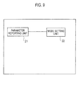
- the radio base station eNB includes a parameter reporting unit 21 and a mode setting unit 22.
- the parameter reporting unit 21 is configured to report a predetermined parameter value to the mobile station UE.
- the predetermined parameter value may be reported as broadcast information or may be reported by dedicated signaling.
- the dedicated signaling may be transmitted by a RRC message, for example.
- the parameter reporting unit 21 is configured to report the maximum allowable transmission power value as the predetermined parameter value.
- the parameter reporting unit 21 may report a value smaller than the maximum transmission power depending on the power class of the mobile station as the value of the maximum allowable transmission power, when the maximum transmission power of the uplink signals in the mobile station UE needs to be reduced.
- the parameter reporting unit 21 may report a larger value or the same value as the maximum transmission power depending on the power class of the mobile station as the value of the maximum allowable transmission power, when the maximum transmission power of the uplink signals in the mobile station UE needs to be increased or when the maximum transmission power of the uplink signals in the mobile station UE does not need to be reduced.
- Exemplary setting of the value of the maximum allowable transmission power is the same as that described for the parameter receiving unit 11 and thus description thereof will be omitted.
- the parameter reporting unit 21 is configured to report the value of the parameter P o_PUSCH (i) and the value of the parameter ⁇ as the predetermined parameter value.
- the value of the parameter P o_PUSCH (i) may be considered as a value equivalent to a target SIR of PUSCH in a subframe i.
- the value of the parameter P o_PUSCH (i) and the value of the parameter ⁇ are used for the determination of the transmission power of the PUSCH or the reference signals for the uplink sounding (Sounding RS), which will be described later.
- the parameter reporting unit 21 may report values so as to reduce the transmission power as the value of the parameter P o_PUSCH (i) and the value of the parameter ⁇ , when the transmission power of the uplink signals in the mobile station UE needs to be reduced.
- the parameter reporting unit 21 may report values so as to increase the transmission power as the value of the parameter P o_PUSCH (i) and the value of the parameter ⁇ , when the transmission power of the uplink signals in the mobile station UE needs to be increased or when the transmission power of the uplink signals in the mobile station UE does not need to be reduced.
- Exemplary setting of the value of the parameter P o_PUSCH (i) and the value of the parameter ⁇ is the same as that described with reference to Figs. 3 and 4 and thus description thereof will be omitted.
- the parameter reporting unit 21 is configured to report the value of the parameter P o_PUSCH (i) as the predetermined parameter value.
- the value of the parameter P o_PUSCH (i) may be considered as a value equivalent to the target SIR of PUCCH in the subframe i.
- the parameter reporting unit 21 may report a value so as to reduce the transmission power, i.e., a small value, as the value of the parameter P o_PUSCH (i) , when the transmission power of the uplink signals in the mobile station UE needs to be reduced.
- the parameter reporting unit 21 may report a value so as to increase the transmission power, i.e., a large value, as the value of the parameter P o_PUSCH (i) , when the transmission power of the uplink signals in the mobile station UE needs to be increased or when the transmission power of the uplink signals in the mobile station UE does not need to be reduced.
- Exemplary setting of the value of the parameter P o_PUSCH (i) is the same as that described for the parameter receiving unit 11 and thus description thereof will be omitted.
- the parameter reporting unit 21 is configured to report the value of the parameter P o_pre (i) as the predetermined parameter value.
- the value of the parameter P o_pre (i) may be considered as a value equivalent to the target SIR of the PRACH in the subframe i.
- the parameter reporting unit 21 may report a value so as to reduce the transmission power, i.e., a small value, as the value of the parameter P o_pre (i), when the transmission power of the uplink signals in the mobile station UE needs to be reduced.
- the parameter reporting unit 21 may report a value so as to increase the transmission power, i.e., a large value, as the value of the parameter P o_pre (i) , when the transmission power of the uplink signals in the mobile station UE needs to be increased or when the transmission power of the uplink signals in the mobile station UE does not need to be reduced.
- Exemplary setting of the value of the parameter P o_pre (i) is the same as that described for the parameter receiving unit 11 and thus description thereof will be omitted.
- the reporting unit 21 reports the predetermined parameter value, in accordance with the "information as to whether or not it is necessary to lower the transmission power of the uplink signals in the mobile station UE" reported from the mode setting unit 22.
- the mode setting unit 22 is configured to determine whether or not the transmission power of the uplink signals in the mobile station UE needs to be reduced and report the determination result to the parameter reporting unit 21.
- the mode setting unit 22 may determine that the transmission power of the uplink signals in the mobile station UE needs to be reduced, when an area in which the radio base station eNB provides a mobile service ("service area”) includes hospitals, airplanes, trains and buildings with highly sensitive measuring instruments and receivers.
- service area an area in which the radio base station eNB provides a mobile service
- the mode setting unit 22 may determine that the transmission power of the uplink signals in the mobile station UE needs to be reduced, when the radio base station eNB is located in hospitals, airplanes, trains and buildings with highly sensitive measuring instruments and receivers.
- the hospitals, airplanes and buildings with highly sensitive measuring instruments and receivers described above may be defined as "places in which radio waves from the mobile station UE affects other electronic equipment" in a broader sense.
- the mode setting unit 22 may determine that the transmission power of the uplink signals in the mobile station UE needs to be reduced, when the radio base station eNB is in the Home Node B.
- the mode setting unit 22 may determine that the transmission power of the uplink signals in the mobile station UE needs to be reduced, when the area in which the radio base station eNB provides the mobile service is a CSG cell.
- the CSG cell is a cell in which only users belonging to a certain specific group can make communication.
- the mode setting unit 22 may determine that the transmission power of the uplink signals in the mobile station UE needs to be reduced regarding a mobile station which communicates in an extension mode.
- the predetermined parameter value may be reported by dedicated signaling to the mobile station UE.
- the mode setting unit 22 may determine that the transmission power of the uplink signals in the mobile station UE needs to be reduced, when the radio base station eNB provides communication in an extension mode.
- the radio base station eNB can reduce, using the maximum allowable transmission power, the maximum transmission power with which the mobile station UE can make transmission in the "places in which radio waves from a mobile station UE affect other electronic equipment", such as hospitals, airplanes and research facilities with highly sensitive measuring instruments and receivers.
- the operation of the above-described mobile station UE or the radio base station eNB may be implemented by a hardware, may also be implemented by a software module executed by a processor, and may further be implemented by the combination of the both.
- the software module may be arranged in a storing medium of an arbitrary format such as RAM (Random Access Memory), a flash memory, ROM (Read Only Memory), EPROM(Erasable Programmable ROM), EEPROM(Electronically Erasable and Programmable ROM), a register, a hard disk, a removable disk, and CD-ROM.
- RAM Random Access Memory
- flash memory ROM (Read Only Memory)
- EPROM Erasable Programmable ROM
- EEPROM Electrically Erasable and Programmable ROM
- register a hard disk, a removable disk, and CD-ROM.
- Such a storing medium is connected to the processor so that the processor can write and read information into and from the storing medium.
- a storing medium may also be accumulated in the processor.
- Such a storing medium and processor may be arranged in ASIC.
- ASIC may be arranged in the mobile station UE or the radio base station eNB.
- As a discrete component, such a storing medium and processor may be arranged in the mobile station UE or the radio base station eNB.
Abstract
A mobile station (UE) according to the present invention includes: a transmission power determining unit (13) configured to determine a transmission power in an uplink shared channel, in accordance with a maximum transmission power value corresponding to power class of the mobile station (UE), the number of resource blocks for the uplink shared channel, path loss between the mobile station (UE) and a radio base station (eNB) which is a connection destination of the uplink shared channel, and transmission power control information received from the radio base station (eNB); wherein when receiving a maximum allowable transmission power value from the radio base station (end) , the transmission power determining unit (13) is configured to determine transmission power in the uplink shared channel, using the maximum allowable transmission power value instead of the maximum transmission power value corresponding to the power class of the mobile station (UE).
Description
- The present invention relates to a mobile station and a radio base station which are configured to control uplink transmission power.
- In mobile communication systems of the LTE (Long Term Evolution) scheme, the maximum transmission power value for an uplink channel with which a mobile station can make transmission is specified in the 3GPP.
- In "places in which radio waves from a mobile station UE affect other electronic equipment", such as hospitals, airplanes and research facilities with highly sensitive measuring instruments and receivers, however, transmission power which is smaller than the above-described maximum transmission power value should sometimes be set to be the maximum transmission power value for an uplink channel with which a mobile station can make transmission.
- The present invention is made in view of the above-described circumference and an object thereof is to provide a mobile station and a radio base station capable of flexibly changing the maximum transmission power for an uplink channel with which transmission can be made.
- A first aspect of the present invention is summarized as a mobile station configured to control a transmission power in an uplink shared channel, including: a transmission power determining unit configured to determine the transmission power in the uplink shared channel, in accordance with a maximum transmission power value corresponding to power class of the mobile station, the number of resource blocks for the uplink shared channel, path loss between the mobile station and a radio base station which is a connection destination of the uplink shared channel, and transmission power control information received from the radio base station; wherein when receiving a maximum allowable transmission power value from the radio base station, the transmission power determining unit is configured to determine transmission power in the uplink shared channel, using the maximum allowable transmission power value instead of the maximum transmission power value corresponding to the power class of the mobile station.
- A second aspect of the present invention is summarized as a mobile station configured to control a transmission power in a physical uplink control channel, including: a transmission power determining unit configured to determine the transmission power in the physical uplink control channel, in accordance with a maximum transmission power value corresponding to power class of the mobile station, path loss between the mobile station and a radio base station which is a connection destination of the physical uplink control channel, and transmission power control information received from the radio base station; wherein when receiving a maximum allowable transmission power value from the radio base station, the transmission power determining unit is configured to determine transmission power in the physical uplink control channel using the maximum allowable transmission power value instead of the maximum transmission power value corresponding to the power class of the mobile station.
- A third aspect of the present invention is summarized as a mobile station configured to control a transmission power in an uplink reference signal, including: a transmission power determining unit conf igured to determine the transmission power in the uplink reference signal, in accordance with a maximum transmission power value corresponding to power class of the mobile station, power offset between the uplink reference signal and an uplink shared channel, the number of resource blocks for the uplink reference signal, path loss between the mobile station and a radio base station which is a connection destination of the uplink reference signal, and transmission power control information received from the radio base station; wherein when receiving a maximum allowable transmission power value from the radio base station, the transmission power determining unit is configured to determine transmission power in the uplink reference signal using the maximum allowable transmission power value instead of the maximum transmission power value corresponding to the power class of the mobile station.
- A fourth aspect of the present invention is summarized as a mobile station configured to control a transmission power in a random access channel, including: a transmission power determining unit configured to determine the transmission power in the random access channel, in accordance with a maximum transmission power value corresponding to power class of the mobile station, power offset corresponding to a preamble format, path loss between the mobile station and a radio base station which is a connection destination of the random access channel, offset for power ramping, and the number of transmission of a preamble; wherein when receiving a maximum allowable transmission power value from the radio base station, the transmission power determining unit is configured to determine transmission power in the random access channel using the maximum allowable transmission power value instead of the maximum transmission power value corresponding to the power class of the mobile station.
- In the first to fourth aspect of the present invention, the transmission power determining unit can be configured to use the maximum allowable transmission power value instead of the maximum transmission power value corresponding to the power class of the mobile station, only when the mobile station is operating in a predetermined mode.
- the first to fourth aspect of the present invention, the transmission power determining unit can be configured to use the maximum allowable transmission power value instead of the maximum transmission power value corresponding to the power class of the mobile station, only when the maximum allowable transmission power value is received from a predetermined radio base station.
- A fifth aspect of the present invention is summarized as a radio base station which communicates with a mobile station configured to control a transmission power in an uplink shared channel, including: a reporting unit configured to report a maximum allowable transmission power value, to the mobile station configured to determine the transmission power in the uplink shared channel in accordance with a maximum transmission power value corresponding to power class of the mobile station, the number of resource blocks for the uplink shared channel, path loss between the mobile station and a radio base station which is a connection destination of the uplink shared channel, and transmission power control information received from the radio base station, wherein: the mobile station is configured to use the maximum allowable transmission power value instead of the maximum transmission power value corresponding to a power class of the mobile station when the maximum allowable transmission power value is received from the radio base station; and the reporting unit is configured to report a value smaller than the maximum transmission power value corresponding to the power class of the mobile station as the maximum allowable transmission power value, when an area in which communication is established between the radio base station and the mobile station is an area in a predetermined range.
- As described above, according to the present invention, a mobile station and a radio base station capable of flexibly changing the maximum transmission power for an uplink channel with which transmission can be made can be provided.
-
- [
Fig. 1] Fig. 1 is a diagram of an entire configuration of a mobile communication system according to a first embodiment of the present invention. - [Fig- 2]
Fig. 2 is a functional block diagram of a mobile station according to the first embodiment of the present invention. - [
Fig. 3] Fig. 3 is a diagram illustrating exemplary setting of parameters in the mobile station according to the first embodiment of the present invention. - [
Fig. 4] Fig. 4 is a diagram illustrating exemplary setting of parameter in the mobile station according to the first embodiment of the present invention. - [
Fig. 5] Fig. 5 is a diagram illustrating an exemplary equation for the determination of transmission power in a PUSCH in the mobile station according to the first embodiment of the present invention. - [
Fig. 6] Fig. 6 is a diagram illustrating an exemplary equation for the determination of transmission power in a PUCCH in the mobile station according to the first embodiment of the present invention. - [
Fig. 7] Fig. 7 is a diagram illustrating an exemplary equation for the determination of transmission power in a "Sounding RS" in the mobile station according to the first embodiment of the present invention. - [
Fig. 8] Fig. 8 is a diagram illustrating an exemplary equation for the determination of transmission power in a PRACH in the mobile station according to the first embodiment of the present invention. - [
Fig. 9] Fig. 9 is a functional block diagram of a radio base station according to the first embodiment of the present invention. - With reference to
Figs. 1 to 8 , a mobile communication system according to a first embodiment of the present invention will be described. The mobile communication system according to the first embodiment of the present invention is a mobile communication system of the LTE scheme. - As illustrated in
Fig. 1 , in the mobile communication system according to the present embodiment, a radio base station eNB is configured to transmit downlink data signals via a physical downlink shared channel PDSCH to a mobile station UE, and to transmit downlink control signals via a physical downlink control channel PDCCH to a mobile station UE. - The mobile station UE is configured to also transmit uplink data signals via a physical uplink shared channel PUSCH to the radio base station eNB, and to transmit uplink control signals via a physical uplink control channel PUCCH to the radio base station eNB.
- The mobile station UE is configured to also transmit a preamble via a physical random access channel PRACH to the radio base station eNB. The mobile station UE is configured to also transmit reference signals for uplink sounding (Sounding RS) . The reference signals for uplink sounding (Sounding RS) may be used for, for example, uplink transmission power control and uplink adaptive modulation encoding.
- As illustrated in
Fig. 2 , the mobile station UE includes aparameter receiving unit 11, amode management unit 12, a transmissionpower determining unit 13 and an uplinksignal transmitting unit 14. - The
parameter receiving unit 11 is configured to receive a predetermined parameter value transmitted from the radio base station eNB. - For example, the
parameter receiving unit 11 is configured to receive the maximum allowable transmission power value as the predetermined parameter value. Here, theparameter receiving unit 11 may be configured to receive the maximum allowable transmission power value as broadcast information or may be configured to receive the maximum allowable transmission power value by dedicated signaling. The dedicated signaling may be reported by, for example, an RRC message. - If, for example, the maximum transmission power of the uplink signals in the mobile station UE needs to be reduced, the radio base station eNB may transmit "18 dBm" as the value of the maximum allowable transmission power. If, alternatively, the maximum transmission power of the uplink signals in the mobile station UE needs to be increased or the maximum transmission power in the mobile station UE does not need to be reduced, the radio base station eNB may transmit "23 dBm" as the value of the maximum allowable transmission power. Here, the "23 dBm" may be the maximum transmission power depending on a power class of the mobile station.
- In particular, when the maximum transmission power of the uplink signals in the mobile station UE needs to be reduced, the value of the maximum allowable transmission power is set to be a value smaller than the maximum transmission power depending on the power class of the mobile station. When the maximum transmission power of the uplink signals in the mobile station UE needs to be increased or the maximum transmission power of the uplink signals in the mobile station UE does not need to be reduced, the value of the maximum allowable transmission power is set to be a value which is larger or the same as the maximum transmission power depending on the power class of the mobile station.
- The
parameter receiving unit 11 is configured to receive a value of a parameter Po_PUSCH(i) and a value of a parameter α as the predetermined parameter value. Here, the value of the parameter Po_PUSCH (i) may be considered as a value equivalent to a target SIR of PUSCH in a subframe i. - The value of the parameter Po_PUSCH (i) and the value of the parameter α are used for the determination of the transmission power of the PUSCH or the reference signals for the uplink sounding (Sounding RS), which will be described latter.
- For example, as illustrated in
Fig. 3 , the radio base station eNB may transmit "-110 dBm" as the value of the parameter Po_PUSCH (i) and "1.0" as the value of the parameter α, when the transmission power of the uplink signals in the mobile station UE needs to be reduced. The radio base station eNB may transmit "-100 dBm" as the value of the parameter Po_PUSCH (i) and "1.0" as the value of the parameter α, when the transmission power of the uplink signals in the mobile station UE needs to be increased or the transmission power of the uplink signals in the mobile station UE does not need to be reduced. - That is, the value of the parameter Po_PUSCH (i) is set to be a small value, when the transmission power of the uplink signals in the mobile station UE needs to be reduced. The value of the parameter Po-PUSCH (i) is set to be a large value, when the transmission power of the uplink signals in the mobile station UE needs to be increased or the transmission power of the uplink signals in the mobile station UE does not need to be reduced.
- As illustrated in
Fig. 4 , the radio base station eNB may transmit "-110 dBm" as the value of the parameter Po_PUSCH (i) and "1.0" as the value of the parameter α, when the transmission power of the uplink signals in the mobile station UE needs to be reduced. The radio base station eNB may transmit "-85 dBm" as the value of the parameter Po_PUSCH (i) and "0.8" as the value of the parameter α, when the transmission power of the uplink signals in the mobile station UE needs to be increased or the transmission power of the uplink signals in the mobile station UE does not need to be reduced. - That is, the value of the parameter Po_PUSCH (i) and the value of the parameter α are set to be values so as to reduce the transmission power, when the transmission power of the uplink signals in the mobile station UE needs to be reduced. The value of the parameter Po_PUSCH (i) is set to be a value so as to increase the transmission power, when the transmission power of the uplink signals in the mobile station UE needs to be increased or the transmission power of the uplink signals in the mobile station UE does not need to be reduced.
- The
parameter receiving unit 11 is configured to receive a value of a parameter Po_PUSCH (i) as the predetermined parameter value. Here, the value of the parameter Po_PUSCH (i) may be considered as a value equivalent to a target SIR of PUCCH in a subframe i. - For example, the radio base station eNB may transmit "-120 dBm" as the value of the parameter Po_PUSCH (i) , when the transmission power of the uplink signals in the mobile station UE needs to be reduced. The radio base station eNB may transmit "-110 dBm" as the value of the parameter Po_PUSCH (i) , when the transmission power of the uplink signals in the mobile station UE needs to be increased or the transmission power of the uplink signals in the mobile station UE does not need to be reduced.
- That is, the value of the parameter Po_PUSCH (i) is set to be a small value, when the transmission power of the uplink signals in the mobile station UE needs to be reduced. The value of the parameter Po_PUSCH (i) is set to be a large value, when the transmission power of the uplink signals in the mobile station UE needs to be increased or the transmission power of the uplink signals in the mobile station UE does not need to be reduced.
- The
parameter receiving unit 11 is configured to receive a value of a parameter Po_pre (i) as the predetermined parameter value. Here, the value of the parameter Po_pre (i) may be considered as a value equivalent to a target SIR of PRACH in a subframe i. - For example, the radio base station eNB may transmit "-115 dBm" as the value of the parameter Po_pre (i), when the transmission power of the uplink signals in the mobile station UE needs to be reduced. The radio base station eNB may transmit "-105 dBm" as the value of the parameter Po_pre (i), when the transmission power of the uplink signals in the mobile station UE needs to be increased or the transmission power of the uplink signals in the mobile station UE does not need to be reduced.
- That is, the value of the parameter Po_pre (i) is set to be a small value, when the transmission power of the uplink signals in the mobile station UE needs to be reduced. The value of the parameter Po_pre (i) is set to be a large value, when the transmission power of the uplink signals in the mobile station UE needs to be increased or the transmission power of the uplink signals in the mobile station UE does not need to be reduced.
- The
mode management unit 12 is configured to manage the mode of the mobile station UE. For example, themode management unit 12 may be configured to manage whether or not the mode of the mobile station UE is an extension mode. - Alternatively, for example, the
mode management unit 12 may be configured to manage whether or not the mode of the mobile station UE is a mode in which it is located in and camping on a Home Node B area, or in a CSG (closed subscriber group) mode. - Here, the Home Node B is a radio base station mainly installed indoors or at ordinary home. The CSG is a group of certain specific users which can communicate with the radio base station. That is, "the mobile station UE is in the CSG mode" means that the mobile station UE is located in and camping on an area of the radio base station belonging to the CSG.
- The transmission
power determining unit 13 is configured to determine the transmission power of the uplink signals. - Specifically, the transmission
power determining unit 13 is configured to determine the transmission power PPUSCH (i) in the uplink shared channel PUSCH in accordance with the following: the maximum transmission power value Pmax corresponding to the power class of the mobile station UE; the number of resource blocks MPUSCH (i) for the uplink shared channel PUSCH in the subframe i; the parameter Po_PUSCH (i) ; the parameter α; path loss PL between the mobile station UE and the radio base station eNB which is a connection destination of the uplink shared channel PUSCH; an offset value in accordance with MCS; and transmission power control information f (i) related to the subframe i received from the radio base station eNB. - For example, the transmission
power determining unit 13 is configured to determine the transmission power PPUSCH (i) in the uplink shared channel PUSCH in accordance with the "Equation 1" given inFig. 5 . - Here, the transmission
power determining unit 13 may be configured to determine, when the maximum allowable transmission power value is received from the radio base station eNB, the transmission power PPUSCH (i) in the uplink shared channel PUSCH using the maximum allowable transmission power value instead of the maximum transmission power value Pmax corresponding to the power class of the mobile station UE. - As described above, values illustrated in
Fig. 3 or 4 may be set for the parameter Po_PUSCH (i) and the parameter α dependent on whether or not the transmission power of the uplink signals in the mobile station UE needs to be reduced. - The transmission
power determining unit 13 is configured to determine the transmission power PPUCCH (i) in the physical uplink control channel PUCCH in accordance with the following: the maximum transmission power value Pmax corresponding to the power class of the mobile station; the parameter Po_PUSCH (i) ; path loss PL between the mobile station UE and the radio base station eNB which is a connection destination of the physical uplink control channel PUCCH; an offset value in accordance with a transmission format of the PUCCH; and transmission power control information g (i) related to the subframe i received from the radio base station eNB. - For example, the transmission
power determining unit 13 is configured to determine the transmission power PPUCCH (i) in the physical uplink control channel PUCCH in accordance with the "Equation 2" given inFig. 6 . - A term of "h (n) " may be added to the "
Equation 2". Here, the "h (n) " is a function depending on the format of the PUCCH and the "n" which is an argument thereof may be the number of bits of the control signals, such as CQI and ACK. That is, the value of the "h (n) " may be determined in accordance with, for example, the format of the PUCCH and the number of bits of the control signals mapped on the PUCCH. - Here, the transmission
power determining unit 13 may be configured to determine, when the maximum allowable transmission power value is received from the radio base station eNB, the transmission power PPUCCH (i) in the physical uplink control channel PUCCH using the maximum allowable transmission power value instead of the maximum transmission power value Pmax corresponding to the power class of the mobile station UE. - As described above, the parameter Po_PUSCH (i) may be set to be a small, when the transmission power of the uplink signals in the mobile station UE needs to be reduced. The parameter Po_PUSCH (i) may be set to be a large value, when the transmission power of the uplink signals in the mobile station UE does not need to be reduced.
- The transmission
power determining unit 13 is configured to determine transmission power PSRS (i) in the reference signal for uplink sounding (Sounding RS), in accordance with the following: the maximum transmission power value Pmax corresponding to the power class of the mobile station UE; a power offset PSRS-QFFSFT between the reference signals for the uplink sounding (Sounding RS) and the uplink shared channel PUSCH; the number of resource blocks MSRS for the reference signals for the uplink sounding (Sounding RS); a parameter Po_PUSCH, the parameter α; path loss PL between the mobile station UE and the radio base station eNB which is a connection destination of the reference signals for the uplink sounding (Sounding RS) ; and transmission power control information f (i) related to the subframe i received from the radio base station eNB. - For example, the transmission
power determining unit 13 is configured to determine the transmission power PSRS (i) in the reference signals for the uplink sounding (Sounding RS) in accordance with the "Equation 3" given inFig. 7 . - Here, the transmission
power determining unit 13 is configured to determine, when the maximum allowable transmission power value is received from the radio base station eNB, the transmission power PSRS (i) in the reference signals for the uplink sounding (Sounding RS) using the maximum allowable transmission power value instead of the maximum transmission power value Pmax corresponding to the power class of the mobile station UE. - As described above, values illustrated in
Fig. 3 or 4 may be set for the parameter Po_PUSCH (i) and the parameter α dependent on whether or not the transmission power of the uplink signals in the mobile station UE needs to be reduced. - The transmission
power determining unit 13 is configured to determine transmission power Pprach in a random access channel PRACH, in accordance with the following: the maximum transmission power value Pmax corresponding to the power class of the mobile station UE; a power offset Δ_preamble; corresponding to a preamble format; path loss PL between the mobile station UE and the radio base station eNB which is a connection destination of the random access channel PRACH; a parameter Po_pre; an offset dP_rampup for power ramping; and the number of transmission N_pre of the preamble. - For example, the transmission
power determining unit 13 is configured to determine the transmission power Pprach in the random access channel PRACH in accordance with the "Equation 4" given inFig. 8 . - Here, the transmission
power determining unit 13 may be configured to determine, when the maximum allowable transmission power value is received from the radio base station eNB, the transmission power Pprach in the random access channel PRACH using the maximum allowable transmission power value instead of the maximum transmission power value Pmax corresponding to the power class of the mobile station UE. - As described above, the parameter Po_pre (i) may be set to be a small, when the transmission power of the uplink signals in the mobile station UE needs to be reduced. The parameter Po_pre (i) may be set to be a large value, when the transmission power of the uplink signals in the mobile station UE does not need to be reduced.
- The transmission
power determining unit 13 may also be configured to use the above-described maximum allowable transmission power value instead of the maximum transmission power value Pmax corresponding to the power class of the mobile station UE, only when the mobile station UE is operating in a predetermined mode (e.g., an extension mode). - The transmission
power determining unit 13 may also be configured to use the above-described maximum allowable transmission power value instead of the maximum transmission power value Pmax corresponding to the power class of the mobile station UE, only when the maximum allowable transmission power value is received from a predetermined radio base station (e. g. , the Home Node B). - Alternatively, the maximum allowable transmission power value may be always reported from the radio base station eNB to the mobile station UE. A value smaller than that of the maximum transmission power value Pmax corresponding to the power class of the mobile station UE may be reported as the maximum allowable transmission power value, when the transmission power of the uplink signals in the mobile station UE needs to be reduced. A value which is the same as the maximum transmission power value Pmax corresponding to the power class of the mobile station UE may be reported as the maximum allowable transmission power value, when the transmission power of the uplink signals in the mobile station UE does not need to be reduced.
- In this case, the transmission
power determining unit 13 may be configured to always use the above-described maximum allowable transmission power value instead of the maximum transmission power value Pmax corresponding to the power class of the mobile station UE. - The uplink
signal transmitting unit 14 may be configured to transmit, with the transmission power determined by the transmissionpower determining unit 13, uplink data signals via the uplink shared channel PUSCH, uplink control signals via the physical uplink control channel PUCCH, the reference signals for the uplink sounding (Sounding RS) and a preamble via the random access channel PRACH. - As illustrated in
Fig. 9 , the radio base station eNB includes aparameter reporting unit 21 and amode setting unit 22. - The
parameter reporting unit 21 is configured to report a predetermined parameter value to the mobile station UE. Here, the predetermined parameter value may be reported as broadcast information or may be reported by dedicated signaling. The dedicated signaling may be transmitted by a RRC message, for example. - For example, the
parameter reporting unit 21 is configured to report the maximum allowable transmission power value as the predetermined parameter value. - Here, the
parameter reporting unit 21 may report a value smaller than the maximum transmission power depending on the power class of the mobile station as the value of the maximum allowable transmission power, when the maximum transmission power of the uplink signals in the mobile station UE needs to be reduced. Theparameter reporting unit 21 may report a larger value or the same value as the maximum transmission power depending on the power class of the mobile station as the value of the maximum allowable transmission power, when the maximum transmission power of the uplink signals in the mobile station UE needs to be increased or when the maximum transmission power of the uplink signals in the mobile station UE does not need to be reduced. Exemplary setting of the value of the maximum allowable transmission power is the same as that described for theparameter receiving unit 11 and thus description thereof will be omitted. - Alternatively, the
parameter reporting unit 21 is configured to report the value of the parameter Po_PUSCH (i) and the value of the parameter α as the predetermined parameter value. Here, the value of the parameter Po_PUSCH (i) may be considered as a value equivalent to a target SIR of PUSCH in a subframe i. - The value of the parameter Po_PUSCH (i) and the value of the parameter α are used for the determination of the transmission power of the PUSCH or the reference signals for the uplink sounding (Sounding RS), which will be described later.
- Here, the
parameter reporting unit 21 may report values so as to reduce the transmission power as the value of the parameter Po_PUSCH (i) and the value of the parameter α, when the transmission power of the uplink signals in the mobile station UE needs to be reduced. Theparameter reporting unit 21 may report values so as to increase the transmission power as the value of the parameter Po_PUSCH (i) and the value of the parameter α, when the transmission power of the uplink signals in the mobile station UE needs to be increased or when the transmission power of the uplink signals in the mobile station UE does not need to be reduced. Exemplary setting of the value of the parameter Po_PUSCH (i) and the value of the parameter α is the same as that described with reference toFigs. 3 and 4 and thus description thereof will be omitted. - Alternatively, the
parameter reporting unit 21 is configured to report the value of the parameter Po_PUSCH (i) as the predetermined parameter value. Here, the value of the parameter Po_PUSCH (i) may be considered as a value equivalent to the target SIR of PUCCH in the subframe i. - Here, the
parameter reporting unit 21 may report a value so as to reduce the transmission power, i.e., a small value, as the value of the parameter Po_PUSCH (i) , when the transmission power of the uplink signals in the mobile station UE needs to be reduced. Theparameter reporting unit 21 may report a value so as to increase the transmission power, i.e., a large value, as the value of the parameter Po_PUSCH (i) , when the transmission power of the uplink signals in the mobile station UE needs to be increased or when the transmission power of the uplink signals in the mobile station UE does not need to be reduced. Exemplary setting of the value of the parameter Po_PUSCH (i) is the same as that described for theparameter receiving unit 11 and thus description thereof will be omitted. - Alternatively, the
parameter reporting unit 21 is configured to report the value of the parameter Po_pre (i) as the predetermined parameter value. Here, the value of the parameter Po_pre (i) may be considered as a value equivalent to the target SIR of the PRACH in the subframe i. - Here, the
parameter reporting unit 21 may report a value so as to reduce the transmission power, i.e., a small value, as the value of the parameter Po_pre (i), when the transmission power of the uplink signals in the mobile station UE needs to be reduced. Theparameter reporting unit 21 may report a value so as to increase the transmission power, i.e., a large value, as the value of the parameter Po_pre (i) , when the transmission power of the uplink signals in the mobile station UE needs to be increased or when the transmission power of the uplink signals in the mobile station UE does not need to be reduced. Exemplary setting of the value of the parameter Po_pre (i) is the same as that described for theparameter receiving unit 11 and thus description thereof will be omitted. - Information as to whether or not the transmission power of the uplink signals in the mobile station UE needs to be reduced, which has been described, is reported from the
mode setting unit 22. That is, thereporting unit 21 reports the predetermined parameter value, in accordance with the "information as to whether or not it is necessary to lower the transmission power of the uplink signals in the mobile station UE" reported from themode setting unit 22. - The
mode setting unit 22 is configured to determine whether or not the transmission power of the uplink signals in the mobile station UE needs to be reduced and report the determination result to theparameter reporting unit 21. - For example, the
mode setting unit 22 may determine that the transmission power of the uplink signals in the mobile station UE needs to be reduced, when an area in which the radio base station eNB provides a mobile service ("service area") includes hospitals, airplanes, trains and buildings with highly sensitive measuring instruments and receivers. - Alternatively, the
mode setting unit 22 may determine that the transmission power of the uplink signals in the mobile station UE needs to be reduced, when the radio base station eNB is located in hospitals, airplanes, trains and buildings with highly sensitive measuring instruments and receivers. - The hospitals, airplanes and buildings with highly sensitive measuring instruments and receivers described above may be defined as "places in which radio waves from the mobile station UE affects other electronic equipment" in a broader sense.
- Alternatively, the
mode setting unit 22 may determine that the transmission power of the uplink signals in the mobile station UE needs to be reduced, when the radio base station eNB is in the Home Node B. Alternatively, themode setting unit 22 may determine that the transmission power of the uplink signals in the mobile station UE needs to be reduced, when the area in which the radio base station eNB provides the mobile service is a CSG cell. Here, the CSG cell is a cell in which only users belonging to a certain specific group can make communication. - Alternatively, the
mode setting unit 22 may determine that the transmission power of the uplink signals in the mobile station UE needs to be reduced regarding a mobile station which communicates in an extension mode. In this case, the predetermined parameter value may be reported by dedicated signaling to the mobile station UE. - Alternatively, the
mode setting unit 22 may determine that the transmission power of the uplink signals in the mobile station UE needs to be reduced, when the radio base station eNB provides communication in an extension mode. - With the mobile communication system according to the present embodiment, the radio base station eNB can reduce, using the maximum allowable transmission power, the maximum transmission power with which the mobile station UE can make transmission in the "places in which radio waves from a mobile station UE affect other electronic equipment", such as hospitals, airplanes and research facilities with highly sensitive measuring instruments and receivers.
- The operation of the above-described mobile station UE or the radio base station eNB may be implemented by a hardware, may also be implemented by a software module executed by a processor, and may further be implemented by the combination of the both.
- The software module may be arranged in a storing medium of an arbitrary format such as RAM (Random Access Memory), a flash memory, ROM (Read Only Memory), EPROM(Erasable Programmable ROM), EEPROM(Electronically Erasable and Programmable ROM), a register, a hard disk, a removable disk, and CD-ROM.
- Such a storing medium is connected to the processor so that the processor can write and read information into and from the storing medium. Such a storing medium may also be accumulated in the processor. Such a storing medium and processor may be arranged in ASIC. Such ASIC may be arranged in the mobile station UE or the radio base station eNB. As a discrete component, such a storing medium and processor may be arranged in the mobile station UE or the radio base station eNB.
- Thus, the present invention has been explained in detail by using the above-described embodiments; however, it is obvious that for persons skilled in the art, the present invention is not limited to the embodiments explained herein. The present invention can be implemented as a corrected, modified mode without departing from the gist and the scope of the present invention defined by the claims. Therefore, the description of the specification is intended for explaining the example only and does not impose any limited meaning to the present invention.
Claims (7)
- A mobile station configured to control a transmission power in an uplink shared channel, comprising:a transmission power determining unit configured to determine the transmission power in the uplink shared channel, in accordance with a maximum transmission power value corresponding to power class of the mobile station, the number of resource blocks for the uplink shared channel, path loss between the mobile station and a radio base station which is a connection destination of the uplink shared channel, and transmission power control information received from the radio base station; whereinwhen receiving a maximum allowable transmission power value from the radio base station, the transmission power determining unit is configured to determine transmission power in the uplink shared channel, using the maximum allowable transmission power value instead of the maximum transmission power value corresponding to the power class of the mobile station.
- A mobile station configured to control a transmission power in a physical uplink control channel, comprising:a transmission power determining unit configured to determine the transmission power in the physical uplink control channel, in accordance with a maximum transmission power value corresponding to power class of the mobile station, path loss between the mobile station and a radio base station which is a connection destination of the physical uplink control channel, and transmission power control information received from the radio base station; whereinwhen receiving a maximum allowable transmission power value from the radio base station, the transmission power determining unit is configured to determine transmission power in the physical uplink control channel using the maximum allowable transmission power value instead of the maximum transmission power value corresponding to the power class of the mobile station.
- A mobile station configured to control a transmission power in an uplink reference signal, comprising:a transmission power determining unit configured to determine the transmission power in the uplink reference signal, in accordance with a maximum transmission power value corresponding to power class of the mobile station, power offset between the uplink reference signal and an uplink shared channel, the number of resource blocks for the uplink reference signal, path loss between the mobile station and a radio base station which is a connection destination of the uplink reference signal, and transmission power control information received from the radio base station; whereinwhen receiving a maximum allowable transmission power value from the radio base station, the transmission power determining unit is configured to determine transmission power in the uplink reference signal using the maximum allowable transmission power value instead of the maximum transmission power value corresponding to the power class of the mobile station.
- A mobile station configured to control a transmission power in a random access channel, comprising:a transmission power determining unit configured to determine the transmission power in the random access channel, in accordance with a maximum transmission power value corresponding to power class of the mobile station, power offset corresponding to a preamble format, path loss between the mobile station and a radio base station which is a connection destination of the random access channel, offset for power ramping, and the number of transmission of a preamble; whereinwhen receiving a maximum allowable transmission power value from the radio base station, the transmission power determining unit is configured to determine transmission power in the random access channel using the maximum allowable transmission power value instead of the maximum transmission power value corresponding to the power class of the mobile station.
- The mobile station according to any one of claims 1 to 4, wherein
the transmission power determining unit is configured to use the maximum allowable transmission power value instead of the maximum transmission power value corresponding to the power class of the mobile station, only when the mobile station is operating in a predetermined mode. - The mobile station according to any one of claims 1 to 4, wherein
the transmission power determining unit is configured to use the maximum allowable transmission power value instead of the maximum transmission power value corresponding to the power class of the mobile station, only when the maximum allowable transmission power value is received from a predetermined radio base station. - A radio base station which communicates with a mobile station configured to control a transmission power in an uplink shared channel, comprising:a reporting unit configured to report a maximum allowable transmission power value, to the mobile station configured to determine the transmission power in the uplink shared channel in accordance with a maximum transmission power value corresponding to power class of the mobile station, the number of resource blocks for the uplink shared channel, path loss between the mobile station and a radio base station which is a connection destination of the uplink shared channel, and transmission power control information received from the radio base station, wherein:the mobile station is configured to use the maximum allowable transmission power value instead of the maximum transmission power value corresponding to a power class of the mobile station when the maximum allowable transmission power value is received from the radio base station; andthe reporting unit is configured to report a value smaller than the maximum transmission power value corresponding to the power class of the mobile station as the maximum allowable transmission power value, when an area in which communication is established between the radio base station and the mobile station is an area in a predetermined range.
Applications Claiming Priority (2)
| Application Number | Priority Date | Filing Date | Title |
|---|---|---|---|
| JP2008243397 | 2008-09-22 | ||
| PCT/JP2009/066222 WO2010032773A1 (en) | 2008-09-22 | 2009-09-17 | Mobile station and wireless base station |
Publications (1)
| Publication Number | Publication Date |
|---|---|
| EP2334124A1 true EP2334124A1 (en) | 2011-06-15 |
Family
ID=42039595
Family Applications (1)
| Application Number | Title | Priority Date | Filing Date |
|---|---|---|---|
| EP09814617A Withdrawn EP2334124A1 (en) | 2008-09-22 | 2009-09-17 | Mobile station and wireless base station |
Country Status (6)
| Country | Link |
|---|---|
| US (1) | US20110281612A1 (en) |
| EP (1) | EP2334124A1 (en) |
| JP (1) | JPWO2010032773A1 (en) |
| KR (1) | KR20110081954A (en) |
| CN (1) | CN102160431A (en) |
| WO (1) | WO2010032773A1 (en) |
Cited By (9)
| Publication number | Priority date | Publication date | Assignee | Title |
|---|---|---|---|---|
| CN103298096A (en) * | 2012-02-23 | 2013-09-11 | 华为技术有限公司 | Method, terminal and base station for controlling data transmission |
| WO2015012502A1 (en) * | 2013-07-26 | 2015-01-29 | Lg Electronics Inc. | Method for adjusting a transmission power |
| EP2706795A4 (en) * | 2011-01-06 | 2015-12-23 | Datang Mobile Comm Equip Co | Uplink power control method, power control parameter configuration method and apparatus thereof |
| EP2696628A4 (en) * | 2010-11-09 | 2016-01-06 | Datang Mobile Comm Equip Co | Power control method and device |
| US9408217B2 (en) | 2012-01-17 | 2016-08-02 | Qualcomm Incorporated | Maximum power reduction for interference control in adjacent channels |
| EP2903355A4 (en) * | 2012-09-26 | 2016-09-28 | Lg Electronics Inc | Method and apparatus for controlling transmission power of uplink control channel |
| WO2018024947A1 (en) * | 2016-08-05 | 2018-02-08 | Nokia Technologies Oy | Power class based coverage enhancement level selection |
| CN110234171A (en) * | 2016-08-12 | 2019-09-13 | 中兴通讯股份有限公司 | A kind of wireless resource allocation method and device |
| EP3761724A4 (en) * | 2018-02-26 | 2021-04-21 | Vivo Mobile Communication Co., Ltd. | Power configuration method and terminal |
Families Citing this family (19)
| Publication number | Priority date | Publication date | Assignee | Title |
|---|---|---|---|---|
| US9059749B2 (en) | 2009-10-02 | 2015-06-16 | Sharp Kabushiki Kaisha | Antenna port mode and transmission mode transitions |
| US8768397B2 (en) | 2009-10-02 | 2014-07-01 | Sharp Kabushiki Kaisha | Transmission power control on a wireless communication device for a plurality of regulated bands or component carriers |
| JP2011249858A (en) | 2010-04-30 | 2011-12-08 | Ntt Docomo Inc | Terminal device, base station device, mobile communication system, and transmission mode setting method |
| JP5427139B2 (en) * | 2010-07-29 | 2014-02-26 | 株式会社日立製作所 | Base station and cellular radio communication system |
| JP4852166B1 (en) | 2010-08-04 | 2012-01-11 | シャープ株式会社 | Mobile station apparatus, communication system, communication method, and integrated circuit |
| CN102781086B (en) * | 2011-05-11 | 2017-06-06 | 中兴通讯股份有限公司 | The Poewr control method and device of a kind of RACH |
| KR102470963B1 (en) | 2011-07-11 | 2022-11-25 | 퀄컴 인코포레이티드 | Method and apparatus for determining transmission power of preamble in wireless communication system |
| CN102300305B (en) * | 2011-09-23 | 2013-09-04 | 电信科学技术研究院 | Method and device for controlling uplink power |
| CN104521169B (en) | 2012-08-01 | 2017-10-03 | Lg 电子株式会社 | The method and its equipment of control information are transmitted with signal |
| CN109756966B (en) * | 2012-11-15 | 2023-09-29 | 华为技术有限公司 | Information transmission method, base station and user equipment |
| JP5864691B1 (en) * | 2014-09-25 | 2016-02-17 | 株式会社Nttドコモ | User terminal, wireless communication method, and wireless communication system |
| WO2017165668A1 (en) * | 2016-03-25 | 2017-09-28 | Intel Corporation | Uplink power control for 5g systems |
| US11234273B2 (en) | 2016-08-12 | 2022-01-25 | Qualcomm Incorporated | RACH conveyance of DL synchronization beam information for various DL-UL correspondence states |
| CN108259149B (en) * | 2016-12-29 | 2023-05-05 | 华为技术有限公司 | Method for transmitting/receiving reference signal, terminal equipment and network equipment |
| KR102270894B1 (en) * | 2017-05-08 | 2021-06-30 | 삼성전자 주식회사 | Method and apparatus for controlling uplink transmission power in wireless communication |
| SG11201911377UA (en) * | 2017-08-09 | 2020-01-30 | Guangdong Oppo Mobile Telecommunications Corp Ltd | Uplink transmission method and terminal device |
| EP3874855A4 (en) * | 2018-11-02 | 2022-07-27 | Lenovo (Beijing) Limited | Determining power offset parameter |
| CN111182618B (en) * | 2018-11-09 | 2021-11-19 | 中国移动通信有限公司研究院 | Data transmission method, sending end equipment and receiving end equipment |
| KR20220102374A (en) * | 2021-01-13 | 2022-07-20 | 삼성전자주식회사 | Electronic device and method for controlling transmitting power based on bluetooth communication |
Family Cites Families (4)
| Publication number | Priority date | Publication date | Assignee | Title |
|---|---|---|---|---|
| US6628956B2 (en) * | 1999-03-15 | 2003-09-30 | Telefonaktiebolaget Lm Ericsson (Publ) | Adaptive power control in a radio communications systems |
| US6882857B2 (en) * | 2002-11-26 | 2005-04-19 | Qualcomm, Incorporated | Method and apparatus for efficient processing of data for transmission in a communication system |
| JP2007110210A (en) * | 2005-10-11 | 2007-04-26 | Matsushita Electric Ind Co Ltd | Mobile communication system and communication terminal |
| US20070123290A1 (en) * | 2005-11-28 | 2007-05-31 | Fredrik Stenmark | Low power transmission mode |
-
2009
- 2009-09-17 KR KR1020117006740A patent/KR20110081954A/en not_active Application Discontinuation
- 2009-09-17 WO PCT/JP2009/066222 patent/WO2010032773A1/en active Application Filing
- 2009-09-17 EP EP09814617A patent/EP2334124A1/en not_active Withdrawn
- 2009-09-17 JP JP2010529784A patent/JPWO2010032773A1/en active Pending
- 2009-09-17 US US13/120,393 patent/US20110281612A1/en not_active Abandoned
- 2009-09-17 CN CN2009801369896A patent/CN102160431A/en active Pending
Non-Patent Citations (1)
| Title |
|---|
| See references of WO2010032773A1 * |
Cited By (18)
| Publication number | Priority date | Publication date | Assignee | Title |
|---|---|---|---|---|
| EP2696628A4 (en) * | 2010-11-09 | 2016-01-06 | Datang Mobile Comm Equip Co | Power control method and device |
| EP2706795A4 (en) * | 2011-01-06 | 2015-12-23 | Datang Mobile Comm Equip Co | Uplink power control method, power control parameter configuration method and apparatus thereof |
| US9408217B2 (en) | 2012-01-17 | 2016-08-02 | Qualcomm Incorporated | Maximum power reduction for interference control in adjacent channels |
| US9713158B2 (en) | 2012-01-17 | 2017-07-18 | Qualcomm Incorporated | Maximum power reduction for interference control in adjacent channels |
| CN103298096B (en) * | 2012-02-23 | 2016-09-14 | 华为技术有限公司 | A kind of method, terminal and base station controlling data transmission |
| CN103298096A (en) * | 2012-02-23 | 2013-09-11 | 华为技术有限公司 | Method, terminal and base station for controlling data transmission |
| US10375649B2 (en) | 2012-09-26 | 2019-08-06 | Lg Electronics Inc. | Method and apparatus for controlling transmission power of uplink control channel |
| EP2903355A4 (en) * | 2012-09-26 | 2016-09-28 | Lg Electronics Inc | Method and apparatus for controlling transmission power of uplink control channel |
| WO2015012502A1 (en) * | 2013-07-26 | 2015-01-29 | Lg Electronics Inc. | Method for adjusting a transmission power |
| WO2018024947A1 (en) * | 2016-08-05 | 2018-02-08 | Nokia Technologies Oy | Power class based coverage enhancement level selection |
| US10779245B2 (en) | 2016-08-05 | 2020-09-15 | Nokia Technologies Oy | Power class based coverage enhancement level selection |
| CN110234171A (en) * | 2016-08-12 | 2019-09-13 | 中兴通讯股份有限公司 | A kind of wireless resource allocation method and device |
| EP3525519A4 (en) * | 2016-08-12 | 2020-04-15 | ZTE Corporation | Wireless resource allocation method and apparatus |
| US11006455B2 (en) | 2016-08-12 | 2021-05-11 | Zte Corporation | Wireless resource allocation method and apparatus |
| CN110234171B (en) * | 2016-08-12 | 2023-04-14 | 中兴通讯股份有限公司 | Wireless resource configuration method and device |
| US11812475B2 (en) | 2016-08-12 | 2023-11-07 | Zte Corporation | Wireless resource allocation method and apparatus |
| EP3761724A4 (en) * | 2018-02-26 | 2021-04-21 | Vivo Mobile Communication Co., Ltd. | Power configuration method and terminal |
| US11375497B2 (en) | 2018-02-26 | 2022-06-28 | Vivo Mobile Communication Co., Ltd. | Power configuration method and terminal |
Also Published As
| Publication number | Publication date |
|---|---|
| CN102160431A (en) | 2011-08-17 |
| WO2010032773A1 (en) | 2010-03-25 |
| US20110281612A1 (en) | 2011-11-17 |
| JPWO2010032773A1 (en) | 2012-02-09 |
| KR20110081954A (en) | 2011-07-15 |
Similar Documents
| Publication | Publication Date | Title |
|---|---|---|
| EP2334124A1 (en) | Mobile station and wireless base station | |
| CN103430477B (en) | For the method strengthening power headroom reporting (PHR) within a wireless communication network | |
| US8023990B2 (en) | Uplink scheduling in a cellular system | |
| EP3289822B1 (en) | Robust selection of prach repetition level for mtc enhanced coverage | |
| US9894621B2 (en) | Power headroom reporting accounting | |
| EP2815605B1 (en) | Methods and devices for adjusting resource management procedures in heterogeneous communication networks based on cell information | |
| KR101823186B1 (en) | Methods and apparatuses for enabling power back-off indication in phr in a telecommunications system | |
| AU2010303058B2 (en) | Methods and arrangements in a mobile telecommunications network | |
| EP3178266B1 (en) | D2d power control | |
| CN110099435B (en) | Method and device for power adjustment in UE and base station | |
| EP2536198A1 (en) | Power headroom processing method and terminal | |
| US8923878B2 (en) | Mobile station, radio base station, and mobile communication method | |
| US11228382B2 (en) | Controlling the channel occupancy measurement quality | |
| EP2487945A1 (en) | Base station device and user device | |
| KR20170080565A (en) | Apparatus and method for power control, reporting and uplink transmission | |
| US10863454B2 (en) | Method and device for transmitting power headroom information in communication system | |
| CN107925547A (en) | The activation of cell | |
| CN105580452A (en) | Method and arrangement for power control handling | |
| CN105934893A (en) | Huawei technologies co., ltd | |
| CN104284365A (en) | Method and apparatus for small cell enhancements in a wireless communication system | |
| JP2015159602A (en) | Method and configuration in communication system | |
| US20220225243A1 (en) | First and second communication devices for power control in groupcast communication | |
| CN102595477B (en) | Method and device for reporting transmission power headroom | |
| WO2010032848A1 (en) | Mobile communication method, mobile communication system, and radio base station | |
| KR101448694B1 (en) | Mobile communication method and mobile station |
Legal Events
| Date | Code | Title | Description |
|---|---|---|---|
| PUAI | Public reference made under article 153(3) epc to a published international application that has entered the european phase |
Free format text: ORIGINAL CODE: 0009012 |
|
| 17P | Request for examination filed |
Effective date: 20110412 |
|
| AK | Designated contracting states |
Kind code of ref document: A1 Designated state(s): AT BE BG CH CY CZ DE DK EE ES FI FR GB GR HR HU IE IS IT LI LT LU LV MC MK MT NL NO PL PT RO SE SI SK SM TR |
|
| AX | Request for extension of the european patent |
Extension state: AL BA RS |
|
| DAX | Request for extension of the european patent (deleted) | ||
| STAA | Information on the status of an ep patent application or granted ep patent |
Free format text: STATUS: THE APPLICATION HAS BEEN WITHDRAWN |
|
| 18W | Application withdrawn |
Effective date: 20140121 |