EP2333921A2 - Electrical junction box - Google Patents
Electrical junction box Download PDFInfo
- Publication number
- EP2333921A2 EP2333921A2 EP10194007A EP10194007A EP2333921A2 EP 2333921 A2 EP2333921 A2 EP 2333921A2 EP 10194007 A EP10194007 A EP 10194007A EP 10194007 A EP10194007 A EP 10194007A EP 2333921 A2 EP2333921 A2 EP 2333921A2
- Authority
- EP
- European Patent Office
- Prior art keywords
- bracket
- throughhole
- junction
- vehicle
- outlet
- Prior art date
- Legal status (The legal status is an assumption and is not a legal conclusion. Google has not performed a legal analysis and makes no representation as to the accuracy of the status listed.)
- Granted
Links
Images


Classifications
-
- B—PERFORMING OPERATIONS; TRANSPORTING
- B60—VEHICLES IN GENERAL
- B60R—VEHICLES, VEHICLE FITTINGS, OR VEHICLE PARTS, NOT OTHERWISE PROVIDED FOR
- B60R16/00—Electric or fluid circuits specially adapted for vehicles and not otherwise provided for; Arrangement of elements of electric or fluid circuits specially adapted for vehicles and not otherwise provided for
- B60R16/02—Electric or fluid circuits specially adapted for vehicles and not otherwise provided for; Arrangement of elements of electric or fluid circuits specially adapted for vehicles and not otherwise provided for electric constitutive elements
- B60R16/023—Electric or fluid circuits specially adapted for vehicles and not otherwise provided for; Arrangement of elements of electric or fluid circuits specially adapted for vehicles and not otherwise provided for electric constitutive elements for transmission of signals between vehicle parts or subsystems
- B60R16/0238—Electrical distribution centers
-
- B—PERFORMING OPERATIONS; TRANSPORTING
- B60—VEHICLES IN GENERAL
- B60R—VEHICLES, VEHICLE FITTINGS, OR VEHICLE PARTS, NOT OTHERWISE PROVIDED FOR
- B60R16/00—Electric or fluid circuits specially adapted for vehicles and not otherwise provided for; Arrangement of elements of electric or fluid circuits specially adapted for vehicles and not otherwise provided for
- B60R16/02—Electric or fluid circuits specially adapted for vehicles and not otherwise provided for; Arrangement of elements of electric or fluid circuits specially adapted for vehicles and not otherwise provided for electric constitutive elements
- B60R16/023—Electric or fluid circuits specially adapted for vehicles and not otherwise provided for; Arrangement of elements of electric or fluid circuits specially adapted for vehicles and not otherwise provided for electric constitutive elements for transmission of signals between vehicle parts or subsystems
- B60R16/0239—Electronic boxes
Definitions
- the present invention relates to an electrical junction box mounted in an engine room of an automobile.
- a moving vehicle incorporates various electronic devices, the moving vehicle being typically, but not limited to, an automobile.
- the automobile has an electrical junction box that incorporates electrical components including a connector, a relay, and a fuse.
- the electrical junction is provided at a predetermined location between a power source and the electronic devices.
- the electrical junction box may be referred to as a junction block, a fuse block, or a relay box.
- the junction block, fuse block, and relay box are hereafter generically referred to as the "electrical junction box.”
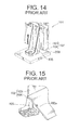
- FIG. 14 is a perspective view illustrating part of such a conventional electrical junction box
- FIG. 15 a perspective view of the electrical junction box illustrated in FIG. 14 viewed from an opposite side thereof.
- the conventional electrical junction box 101 (for example, see Japanese Patent Application Laid-Open Publication No. 2000-125450 ) comprises a junction-box body 102 that has an outlet 102a for discharging water that may reside inside thereof, and a bracket 105 adapted to attach the junction-box body 102 to a vehicle-body panel 200.
- the junction-box body 102 takes a shape of a box defined by outer walls 103, 104, inside of which various electrical components (not shown) are accommodated.
- the outlet 102a extends through the outer wall 104 of the junction-box body 102, the outer wall 104 facing the vehicle-body panel 200.
- the bracket 105 resides between the junction-box body 102 and the vehicle-body panel 200.
- a bolt may be inserted into the bracket 105 and screwed to the vehicle-body panel 200, so that the junction-box body 102 is attached to the vehicle-body panel 200 via the bracket 105 (see FIG. 14 ).
- a gap may exist between the outer wall 104 having the outlet 102a and the vehicle-body panel 200. This means that an opening of the outlet 102a may be exposed to an outside of the outer wall 104.
- the engine room in which the conventional electrical junction box 101 is mounted may be washed under application of pressurized water (i.e., subjected to high-pressure washing). Understandably, as the automobile is high-pressure-washed, water used in the high-pressure washing may enter an inside of the junction-box body 102 of the electrical junction box 101 via the opening of the outlet 102a.
- an object of the present invention is to provide an electrical junction box that is capable of preventing entry of the water into the inside of the junction-box body via the outlet provided in the junction-box body and promptly discharging the water that entered the inside of the junction-box body, which may be due to dew condensation, to the outside of the junction-box body.
- an electrical junction box comprises a junction-box body having an outlet adapted to discharge a liquid residing inside of the junction-box body; and a bracket adapted to attach the junction-box body to a vehicle-body panel.
- the bracket is provided between the junction-box body and the vehicle-body panel such that the bracket is provided in a lower space relative to the junction-box body in a vertical direction.
- the bracket includes a throughhole that is adapted to communicate with the outlet of the junction-box body.
- the throughhole is configured to guide the liquid via the outlet to an outside.
- one end of the throughhole opens at a portion of the bracket where the throughhole is brought into communication with the outlet of the junction-box body, and an other end of the throughhole away from the one end opens at a connection surface of the bracket.
- the connection surface is adapted to be disposed in an overlapping manner on the vehicle-body panel so as to attach the bracket to the vehicle-body panel.
- the vehicle-body panel is provided slantingly with respect to the vertical direction
- the connection surface extends in a slanting fashion corresponding to the slantingly-provided vehicle-body panel
- the connection surface includes a first groove communicating with the throughhole and extending from the throughhole to a lower end of the slantingly-provided connection surface.
- the slantingly-provided connection surface includes a second groove communicating with the throughhole and extending from the throughhole to a higher end of the slantingly-provided connection surface.
- the bracket includes a plurality of ribs spaced from each other and upstanding in a shape of a plate toward the vehicle-body panel, and the outlet is provided between the ribs.
- the electrical junction box further comprises a foot upstanding in a shape of a plate toward the vehicle-body panel, the foot being configured to connect the ribs to each other.
- the electrical junction box according to one embodiment of the present invention has liquid-entry-prevention and liquid-discharging features advantageous effects of which includes, but not limited to, the following aspects.
- the bracket includes the throughhole that communicates with the outlet so as to guide the liquid via the outlet to the outside
- the outlet is covered by the bracket, so that the water as the liquid will not be in direct contact with the opening of the outlet, and thus it is made possible to prevent the water from entering the inside of the junction-box body via the outlet, and obtain the electrical junction box that, by virtue of the throughhole in communication with the outlet, can promptly discharge the water entering the inside of the junction-box body, which may be due to dew condensation, to the outside.
- the water can be prevented from entering the inside of the junction-box body via the outlet, and by virtue of the throughhole in communication with the outlet, the water entering the inside of the junction-box body, which may be due to dew condensation, can be promptly discharged to the outside.
- the vehicle-body panel may be provided slantingly with respect to the vertical direction, and the connection surface is constructed to communicate with the throughhole, and there is provided the first groove that extends from the throughhole to the lower portion of the end of the connection surface, the water entering the inside of the junction-box body can be more promptly discharged via the outlet and the throughhole, and from the first groove to the outside.
- connection surface communicates with the throughhole and the second groove may preferably be provided to force the water droplet attached to the inside of the outlet and the throughhole to get out of the throughhole with the air inside of the junction-box body passed through the outlet, the throughhole, and the second groove in this order.
- the throughhole may be constituted by the plurality of ribs spaced from each other without the need of individually providing the throughhole as such, which makes it possible to reduce the manufacturing costs in manufacturing process of the bracket (and accordingly the electrical junction box), and further it is made possible to make the bracket more light-weighted. Also, by virtue of the ribs, the water can be effectively prevented from entering the inside of the junction-box body via the outlet.
- the foot that upstands in a plate-like manner toward the vehicle-body panel and configured to connect the ribs to each other, the strength of the foot, and accordingly the strength of the bracket can be ensured. Also, by virtue of the foot, it is possible to further effectively prevent the water from entering the inside of the junction-box body via the outlet.
- junction box 1 An electrical junction box according to a first exemplary embodiment of the present invention is described below in detail with reference to FIGS. 1 to 9 .
- a junction block, a fuse block, and a relay box may be generically referred to as the electrical junction box 1.
- the electrical junction box 1 is adapted to be mounted in an engine room of an automobile to power various electronic components incorporated in the automobile.
- the electrical junction box 1 takes a shape of a box and comprises (a) a junction-box body 2 configured to accommodate various electrical components (not shown) therein and (b) a bracket 3 adapted to attach the junction-box body 2 to a vehicle-body panel 200 constituting (part of) a body of the automobile.
- the junction-box body 2 includes a body portion 4 defmed by a plurality of walls 8, 9, 10 to have a shape of a bottomed cylinder, and an upper cover 5 detachably attached to a top surface of the body portion 4, the upper cover 5 residing in an upper half region in FIGS. 2 and 3 .
- the upper cover 5 is also made in a shape of a bottomed cylinder.
- An arrow K illustrated in FIGS. 2 and 3 represents a direction orthogonal to the top surface of the body portion 4.
- the upper cover 5 and the body portion 4 will be moved close to each other along the arrow K.
- the bracket 3 is to be mounted to the body portion 4, the body portion 4 and the bracket 3 will be moved close to each other along the arrow K.
- the arrow K is a direction in which the upper cover 5 and the bracket 3 are moved close to the body portion 4. Also, the arrow K is a direction parallel to a "vertical direction" as used in the appended claims.
- the electrical junction box 1 is arranged and oriented such that the arrow K becomes parallel to the vertical direction.
- the body portion 4 is made of synthetic resin and formed by known injection molding.
- the body portion 4 has a bottomed-cylindrical shape defined by the bottom wall 8 opposite the top surface and the sidewalls 9, 10 each continuing to the bottom wall 8.
- the body portion 4 includes a plurality of locking projections 16 configured to be brought into locking with a locking arm 20 of the upper cover 5, which will be described later; a plurality of protrusions 17 configured to be brought into locking with a locking lance 30 of the bracket 3, which also will be described later; and a pair of first guide portions 18 configured to be brought into engagement with a second guide portion 31 of the bracket 3.
- the bracket 3 is attached to a corner of the body portion 4, the corner being near the bottom wall 8.
- the corner of the body portion 4 to which the bracket 3 is attached is depressed inward with reference to the body portion 4, the depressed contour of the corner being defined by inner walls 13, 15 of the sidewalls 9, 10.
- the bottom wall 8 includes an outlet 11 extending therethrough, which is illustrated in FIGS. 4, 5 , and 6 .
- the sidewall 9 is constituted by a body wall 12 and the inner wall 13 continuing to the body wall 12, the inner wall 13 being depressed inward of the body portion 4.
- the sidewall 10 is constituted by a body wall 14 and the inner wall 15 continuing to the body wall 12, the inner wall 15 being depressed inward of the body portion 4.
- an entry portion 19 at a distal end away from the top surface of the body wall 14.
- the entry portion 19 protrudes in a direction away from the top surface along the arrow K, such that the entry portion 19 is allowed to enter an entry-accommodating portion 32 provided in a second wall portion 23 of the bracket 3 (which are to be described later in detail).
- the protrusion 17 protrudes from an outer surface of the inner walls 13, 15. Also, the protrusion 17 tapers such that an amount of protrusion thereof increases gradually as it becomes away from an edge of the inner walls 13, 15 continuing to the bottom wall 8. Also, the protrusion 17 is configured to be brought into locking with the locking lance 30 provided on the bracket 3. The bracket 3 is attached to the junction-box body 2 with the protrusion 17 locked with the locking lance 30.
- the first guide portion 18 is formed in an L-shape in plan view. Also, a pair of the first guide portions 18 are provided such that the protrusion 17 is provided therebetween, with one end continuous to the inner wall 13, 15, and the other end oriented in a direction away from each other. Also, the first guide portion 18 is configured to be brought into engagement with a second guide portion 31 of the bracket 3 and guide the body portion 4 and the bracket 3 so that they are moved close to each other along the arrow K with the first and second guiding portions 18, 31 brought into engagement with each other.
- the upper cover 5 is made of synthetic resin and formed by known injection molding.
- the upper cover 5 includes a plurality of the locking arms 20.
- the upper cover 5 is attached to the body portion 4 with the locking arm 20 of the upper cover 5 brought into engagement with the locking projection 16 of the body portion 4.
- the bracket 3 is made of synthetic resin and formed by known injection molding. As shown in FIGS. 6 and 7 , the bracket 3 includes: (a) a base portion 6 with a throughhole 25 provided therein that is configured to communicate with the outlet 11 in the bottom wall 8 of the body portion 4; and (b) a flange portion 7 continuing to the base portion 6 and adapted to be disposed in an overlapping manner on the vehicle-body panel 200.
- the bracket 3 is arranged between the junction-box body 2 and the vehicle-body panel 200 such that the bracket 3 resides in a lower space with respect to the inside of the junction-box body 2 in the vertical direction (i.e., the direction indicated by the arrow K).
- the base portion 6 has a rectangular shape and includes: (i) a platform portion 21 having an overlapping surface 26 adapted to be disposed in an overlapping manner on the bottom wall 8 of the body portion 4 and (ii) a connection surface 27 (illustrated in FIG.
- a first wall portion 22 extending from an end of the overlapping surface 26 along the arrow K and adapted to be disposed in an overlapping manner on the inner wall 13 of the sidewall 9;
- a second wall portion 23 continuing to ends of the first wall portion 22 and the overlapping surface 26 and adapted to be disposed in an overlapping manner on the inner wall 15 of the sidewall 10;
- a plurality of the locking lances 30 adapted to be brought into locking with the protrusion 17 of the inner wall 13, 15; and a pair of the second guide portions 31 adapted to be engaged with the first guide portion 18.
- an entry-accommodating portion 32 at an end on the side away from the platform portion 21 of the second wall portion 23.
- the entry-accommodating portion 32 has such a concave shape that the entry portion 19 of the body wall 14 can be accommodated therein.
- the throughhole 25 extends through the overlapping surface 26 and the connection surface 27 along the arrow K (extending on a straight line), and the throughhole 25 has its one end opening on the overlapping surface 26 and its other end away from the one end opening on the connection surface 27. Also, the throughhole 25 is provided such that it is brought into communication with the outlet 11 provided in the bottom wall 8 when the overlapping surface 26 of the platform portion 21 is disposed in the overlapping manner on the bottom wall 8 of the body portion 4, so that water as a liquid entering or residing in the inside of the junction-box body 2 can be guided via the outlet 11 and the throughhole 25 in communication therewith.
- the platform portion 21 is provided in a direction in which the connection surface 27 intersects with the overlapping surface 26. Also, in this embodiment, in view of the design of the vehicle body, the vehicle-body panel 200 is provided slantingly with respect to the vertical direction (i.e., the direction indicated by the arrow K).
- connection surface 27 is disposed in an overlapping manner on the vehicle-body panel 200 and the overlapping surface 26 is disposed in an overlapping manner on the bottom wall 8 of the junction-box body 2
- the junction-box body 2 is arranged in the direction in which the top surface crosses at right angles the arrow K.
- connection surface 27 includes a first groove 28 and a second groove 29.
- the first groove 28 and the second groove 29 are provided such that both of them rest on a single straight line.
- the first groove 28 is recessed from and with reference to the connection surface 27 and is constructed to communicate with the throughhole 2.
- the first groove 27 extends from the throughhole 25 down to a lower portion of the end of the connection surface 27.
- the first groove 28 is adapted to discharge the water inside of the junction-box body that has been passed through the outlet 11 and the throughhole 25 to the outside.
- the second groove 29 is recessed from and with reference to the connection surface 27 and is constructed to communicate with the throughhole 2.
- the second groove 29 extends from the throughhole 25 down to a higher portion of the end of the connection surface 27.
- the second groove 29 is adapted to force the water droplet attached to the inside of the outlet 11 and the throughhole 25 to get out of the throughhole 25 with the air inside of the junction-box body 2 passed through the outlet 11, the throughhole 25, and the second groove 29 in this order.
- the "lower portion" of the end of the connection surface 27 indicates a portion lower in the vertical direction, i.e., the direction indicated by the arrow K (i.e., a lower side in FIG. 5 ) and the "higher portion" of the end of the connection surface 27 indicates a portion higher in the same vertical direction, i.e., an upper side in FIG. 5 .
- the locking lance 30 protrudes from an inner surface of the walls 22, 23.
- the locking lance 30 has one end thereof continuing to each of the inner surfaces, and the other end thereof being a free end and elastically deformable in the directions toward and away from the inner surface.
- the second guide portion 31 is formed in an L-shape in plan view. A pair of the second guide portions 31 are provided such that the locking lance 30 is provided therebetween with one ends of the pair each continuing to the walls 22, 23 and the other ends thereof oriented in a direction toward each other.
- the flange portion 7 is formed in a shape of a plate that extends along the vehicle-body panel 200.
- a hole portion 7a is provided at the center of the flange portion 7, through which a bolt is passed.
- the following describes assembling operation of the electrical junction box 1. First, the electrical components are accommodated in the body portion 4.
- the upper cover 5 is mounted to the body portion 4 in the following manner.
- the upper cover 5 is moved close to the body portion 4 until the top surface of the body portion 4 is covered by the upper cover 5 with the locking arm 20 of the upper cover 5 brought into engagement with the locking portion 16 of the body portion 4.
- junction-box body 2 and the bracket 3 are moved close to each other along the arrow K in the following manner.
- the bracket 3 is moved close to the corner of the body portion 4 of the junction-box body 2, and the junction-box body 2 and the bracket 3 are positioned at the position where the bottom wall 8 and the overlapping surface 26 of the platform portion 21 are disposed on each other in the overlapping manner such that the inner surface of the inner walls 13, 15 and the outer surface of the walls 22, 23 are overlapped with each other.
- the first guide portion 18 and the second guide portion 31 are brought into engagement with each other.
- the locking lance 30 is again restored to the neutral state by virtue of the resilient restoring force, and thereby, simultaneously with the protrusion 17 being locked with the locking lance 30, the entry portion 19 enters the entry-accommodating portion 32, so that the bracket 3 is mounted to the junction-box body 2. In this manner, the electrical junction box 1 is assembled.
- the flange portion 7 is disposed in an overlapping manner on the vehicle-body panel 200, and the bolt passing inside of the hole portion 7a is screwed onto a nut attached to the vehicle-body panel 200, so that the electrical junction box 1 is mounted to the vehicle-body panel 200.
- the electrical junction box 1 comprises the junction-box body 2 having the above described construction and arrangement and the bracket 3 having the above-described construction and arrangement. Since the bracket 3 includes the throughhole 25 that communicates with the outlet 11 so as to guide the liquid via the outlet 11 to the outside, the outlet 11 is covered by the bracket 3, so that the water as the liquid will not be in direct contact with the opening of the outlet 11, and thus it is made possible to prevent the water from entering the inside of the junction-box body 2 via the outlet 11, and obtain the electrical junction box 1 that, by virtue of the throughhole 25 in communication with the outlet 11, can promptly discharge the water entering the inside of the junction-box body 2, which may be due to dew condensation, to the outside.
- the one end of the throughhole 25 opens at the location where the throughhole 25 is brought into communication with the outlet 11, and the other end on the side away from the one end is provided at the location where it opens at the connection surface 27 to be disposed in the overlapping manner on the vehicle-body panel 200. Accordingly, the water can be prevented from entering the inside of the junction-box body 2 via the outlet 11, and by virtue of the throughhole 25 in communication with the outlet 11, the water entering the inside of the junction-box body 2, which may be due to dew condensation, can be promptly discharged to the outside.
- the vehicle-body panel 200 is provided slantingly with respect to the vertical direction K, and the connection surface 27 is constructed to communicate with the throughhole 2, and there is provided the first groove 28 that extends from the throughhole 25 to the lower portion of the end of the connection surface 27. Accordingly the water entering the inside of the junction-box body 2 can be more promptly discharged via the outlet 11 and the throughhole 25, and from the first groove 28 to the outside.
- connection surface 27 is configured to communicate with the throughhole 2, and the second groove 2 that extends from the throughhole 25 to the higher portion of the end of the connection surface 27 residing in a high space relative to the connection surface 27. Accordingly, the air inside of the junction-box body 2 passes through the outlet 11, the throughhole 25, and the second groove 29 in this order, so that the water droplet attached to the inside of the outlet 11 and the throughhole 25 can be forced to the outside of the throughhole 25.
- junction-box body 2 and the bracket 3 of this embodiment are two discrete elements that are individually-provided.
- the present invention is not limited to this construction; the junction-box body 2 and the bracket 3 may be provided in one piece therewith.
- one end of the throughhole 25 opens at a location where the throughhole 25 is brought into communication with the outlet 11, the other end on the side away from the one end is provided at the location where it opens at the connection surface 27 to be disposed in the overlapping manner on the vehicle-body panel 200.
- the throughhole 25 is formed in the linear fashion along the arrow K.
- the present invention is not limited to this specific construction.
- the throughhole 25 does not need to be formed in the linear fashion along the arrow K (it may be formed in a curved fashion).
- connection surface 27 of this embodiment includes the first groove 28 and the second groove 29.
- the present invention is not limited to this specific construction; it is also possible to only provide either one of the first groove 28 and the second groove 29. Further, the first groove 28 and the second groove 29 may be both omitted.
- FIGS. 10 to 13 An electrical junction box 1' according to a second embodiment of the present invention is described below in detail with reference to FIGS. 10 to 13 , in which the same reference signs are assigned to the same elements as those described in the context of the first embodiment, whose discussion will not be repeated.
- the electrical junction box 1' includes a junction-box body 2' accommodating various electrical components (not shown) therein; and a bracket 3' configured to attach the junction-box body 2' to a vehicle-body panel 200 constituting part of an automobile's body.
- the junction-box body 2' includes a body (not shown) in a shape of a box having an opening defined by a plurality of not-shown peripheral walls; and a lower cover 33 detachably attached to the body such that the opening is covered thereby.
- the body is made of synthetic resin and formed by known injection molding.
- the body includes a lock-part-receiver part (not shown) adapted to be brought into locking with a lock part 35 of the lower cover 33.
- the lower cover 33 is made of synthetic resin and formed by known injection molding. Also, the lower cover 33 includes a bottom wall 8'; a plurality of peripheral walls 34A, 34B upstanding from an edge of the bottom wall 8'; and a plurality of lock parts 35.
- the lower cover 33 has a shape of a bottomed cylinder defined by the bottom wall 8' and the plurality of peripheral walls 34A, 34B. Also, the bottom wall 8' includes a plurality of outlets 11' extending through the bottom wall 8'.
- the bracket 3' is made of synthetic resin and formed by known injection molding.
- the bracket 3' includes a plurality of ribs 36 upstanding from the bottom wall 8' toward the vehicle-body panel 200 in a plate-like manner; a foot 37 upstanding from the peripheral wall 34A of the lower cover 33 toward the vehicle-body panel 200 in a plate-like manner and connecting the plurality of ribs 36; and a flange portion 7 continuing to the foot 37 and adapted to be disposed in an overlapping manner on the vehicle-body panel 200.
- the bracket 3' is provided between the junction-box body 2' and the vehicle-body panel 200.
- the bracket 3 is positioned in a lower space relative to the junction-box body 2 in the vertical direction (i.e., the direction indicated by the arrow K). Also, in this embodiment, the bracket 3' is made in one piece with the lower cover 33 (junction-box body 2').
- the ribs 36 are spaced from each other such that each outlet 11' is positioned between the ribs 36. Also, in this embodiment, a space between the ribs 36 is referred to as a throughhole 25'.
- the throughhole 25' is provided at a location where the throughhole 25' is in communication with the outlet 11' provided in the bottom wall 8' so as to guide the water as the liquid that entered the inside of the junction-box body 2' to the outside via the outlet 11'.
- the outlet 11' is provided at a position spaced from the foot 37.
- the following describes assembling operation of the electrical junction box 1'.
- the electrical components are accommodated in the inside of the body.
- the lower cover 33 is moved close to the body such that the opening of the body is covered thereby, and the lower cover 33 is attached to the body with the lock part 35 of the lower cover 33 brought into engagement with the lock-part-receiver part of the body.
- the junction-box body 2' is assembled and the electrical junction box 1' is also assembled, for the lower cover 33 includes the bracket 3' in one piece therewith.
- the bracket 3' includes the plurality of ribs 36 spaced from each other and upstanding toward the vehicle-body panel 200 in the plate-like manner, and the outlet 11' is provided between the plurality of ribs 36.
- the throughhole 25' is constituted by the plurality of ribs 36 spaced from each other without the need of individually providing the throughhole 25' as such, which makes it possible to reduce the manufacturing costs in manufacturing process of the bracket 3' (and accordingly the electrical junction box 1'), and further it is made possible to make the bracket 3' more light-weighted. Also, by virtue of the ribs 36, the water can be prevented from entering the inside of the junction-box body 2' via the outlet 11'.
- the foot 37 upstanding in the plate-like manner toward the vehicle-body panel 200 and configured to connect the ribs 36 to each other, the strength of the foot 37, and accordingly the strength of the bracket 3' can be ensured. Also, by virtue of the foot 37, it is possible to further effectively prevent the water from entering the inside of the junction-box body 2' via the outlet 11'.
- junction-box body 2' and the bracket 3' of this embodiment are two discrete elements that are individually provided, the present invention is not limited to this specific construction.
- the junction-box body 2' and the bracket 3' may be provided in one piece therewith.
Landscapes
- Engineering & Computer Science (AREA)
- Mechanical Engineering (AREA)
- Connection Or Junction Boxes (AREA)
Abstract
Description
- This application claims priority to Japanese Patent Application No.
2009-282744 filed on December 14, 2009 2010-139394 filed on June 18, 2010 - The present invention relates to an electrical junction box mounted in an engine room of an automobile.
- A moving vehicle incorporates various electronic devices, the moving vehicle being typically, but not limited to, an automobile. In order to power these electronic devices, the automobile has an electrical junction box that incorporates electrical components including a connector, a relay, and a fuse. The electrical junction is provided at a predetermined location between a power source and the electronic devices.
- The electrical junction box may be referred to as a junction block, a fuse block, or a relay box. In this description, the junction block, fuse block, and relay box are hereafter generically referred to as the "electrical junction box."
-
FIG. 14 is a perspective view illustrating part of such a conventional electrical junction box, andFIG. 15 a perspective view of the electrical junction box illustrated inFIG. 14 viewed from an opposite side thereof. The conventional electrical junction box 101 (for example, see Japanese Patent Application Laid-Open Publication No.2000-125450 box body 102 that has anoutlet 102a for discharging water that may reside inside thereof, and abracket 105 adapted to attach the junction-box body 102 to a vehicle-body panel 200. - The junction-
box body 102 takes a shape of a box defined byouter walls - The
outlet 102a extends through theouter wall 104 of the junction-box body 102, theouter wall 104 facing the vehicle-body panel 200. - The
bracket 105 resides between the junction-box body 102 and the vehicle-body panel 200. A bolt may be inserted into thebracket 105 and screwed to the vehicle-body panel 200, so that the junction-box body 102 is attached to the vehicle-body panel 200 via the bracket 105 (seeFIG. 14 ). - As shown in
FIG 14 , in the state where the junction-box body 102 is attached to the vehicle-body panel 200 via thebracket 105, a gap may exist between theouter wall 104 having theoutlet 102a and the vehicle-body panel 200. This means that an opening of theoutlet 102a may be exposed to an outside of theouter wall 104. - The engine room in which the conventional
electrical junction box 101 is mounted may be washed under application of pressurized water (i.e., subjected to high-pressure washing). Understandably, as the automobile is high-pressure-washed, water used in the high-pressure washing may enter an inside of the junction-box body 102 of theelectrical junction box 101 via the opening of theoutlet 102a. - In view of the above drawback found in the conventional electrical junction box, an object of the present invention is to provide an electrical junction box that is capable of preventing entry of the water into the inside of the junction-box body via the outlet provided in the junction-box body and promptly discharging the water that entered the inside of the junction-box body, which may be due to dew condensation, to the outside of the junction-box body.
- In order to provide solution to the above-identified problem, an electrical junction box according to one embodiment of the present invention comprises a junction-box body having an outlet adapted to discharge a liquid residing inside of the junction-box body; and a bracket adapted to attach the junction-box body to a vehicle-body panel. The bracket is provided between the junction-box body and the vehicle-body panel such that the bracket is provided in a lower space relative to the junction-box body in a vertical direction.
- The bracket includes a throughhole that is adapted to communicate with the outlet of the junction-box body. The throughhole is configured to guide the liquid via the outlet to an outside.
- Preferably, one end of the throughhole opens at a portion of the bracket where the throughhole is brought into communication with the outlet of the junction-box body, and an other end of the throughhole away from the one end opens at a connection surface of the bracket. The connection surface is adapted to be disposed in an overlapping manner on the vehicle-body panel so as to attach the bracket to the vehicle-body panel.
- Preferably, the vehicle-body panel is provided slantingly with respect to the vertical direction, the connection surface extends in a slanting fashion corresponding to the slantingly-provided vehicle-body panel, and the connection surface includes a first groove communicating with the throughhole and extending from the throughhole to a lower end of the slantingly-provided connection surface.
- Preferably, the slantingly-provided connection surface includes a second groove communicating with the throughhole and extending from the throughhole to a higher end of the slantingly-provided connection surface.
- Preferably, the bracket includes a plurality of ribs spaced from each other and upstanding in a shape of a plate toward the vehicle-body panel, and the outlet is provided between the ribs.
- Preferably, the electrical junction box further comprises a foot upstanding in a shape of a plate toward the vehicle-body panel, the foot being configured to connect the ribs to each other.
- With the construction and arrangement described above, the electrical junction box according to one embodiment of the present invention has liquid-entry-prevention and liquid-discharging features advantageous effects of which includes, but not limited to, the following aspects.
- Since the bracket includes the throughhole that communicates with the outlet so as to guide the liquid via the outlet to the outside, the outlet is covered by the bracket, so that the water as the liquid will not be in direct contact with the opening of the outlet, and thus it is made possible to prevent the water from entering the inside of the junction-box body via the outlet, and obtain the electrical junction box that, by virtue of the throughhole in communication with the outlet, can promptly discharge the water entering the inside of the junction-box body, which may be due to dew condensation, to the outside.
- Since the one end of the throughhole opens at the location where the throughhole is brought into communication with the outlet, and the other end on the side away from the one end is provided at the location where it opens at the connection surface to be disposed in the overlapping manner on the vehicle-body panel, the water can be prevented from entering the inside of the junction-box body via the outlet, and by virtue of the throughhole in communication with the outlet, the water entering the inside of the junction-box body, which may be due to dew condensation, can be promptly discharged to the outside.
- Since the vehicle-body panel may be provided slantingly with respect to the vertical direction, and the connection surface is constructed to communicate with the throughhole, and there is provided the first groove that extends from the throughhole to the lower portion of the end of the connection surface, the water entering the inside of the junction-box body can be more promptly discharged via the outlet and the throughhole, and from the first groove to the outside.
- Since the connection surface communicates with the throughhole and the second groove may preferably be provided to force the water droplet attached to the inside of the outlet and the throughhole to get out of the throughhole with the air inside of the junction-box body passed through the outlet, the throughhole, and the second groove in this order.
- Since the space between the ribs preferably serves as the throughhole, the throughhole may be constituted by the plurality of ribs spaced from each other without the need of individually providing the throughhole as such, which makes it possible to reduce the manufacturing costs in manufacturing process of the bracket (and accordingly the electrical junction box), and further it is made possible to make the bracket more light-weighted. Also, by virtue of the ribs, the water can be effectively prevented from entering the inside of the junction-box body via the outlet.
- Since there is preferably provided the foot that upstands in a plate-like manner toward the vehicle-body panel and configured to connect the ribs to each other, the strength of the foot, and accordingly the strength of the bracket can be ensured. Also, by virtue of the foot, it is possible to further effectively prevent the water from entering the inside of the junction-box body via the outlet.
- Although the novel and inventive features believed characteristic of the present invention are set forth in the appended claims, the invention itself, however, a preferred mode of application or usage thereof, and further objectives and advantages thereof will best be understood upon reading of the following detailed description of illustrative embodiments with reference made to the accompanying drawings, wherein:
-
FIG. 1 is a perspective view of a partly illustrated electrical junction box according to a first embodiment of the present invention; -
FIG. 2 is a perspective view illustrating assembling operation of the electrical junction box illustrated inFIG. 1 , in which a bracket is being mounted to a junction-box body of the same electrical junction box; -
FIG. 3 is a perspective view of the electrical junction box illustrated inFIG. 2 viewed from an opposite side thereof; -
FIG. 4 is a top view illustrating a state where an upper cover of the electrical junction box illustrated inFIG. 1 is detached; -
FIG. 5 is a cross-sectional view schematically illustrating a configuration of the electrical junction box illustrated inFIG. 4 taken along the line I-I inFIG. 4 ; -
FIG. 6 is a bottom view of the electrical junction box illustrated inFIG 4 ; -
FIG. 7 is a perspective view schematically illustrating a configuration of the bracket of the electrical junction box illustrated inFIG. 1 ; -
FIG. 8 is a perspective view of the electrical junction box illustrated inFIG. 7 , in which the bracket is attached to a vehicle-body panel; -
FIG. 9 is a perspective view of the bracket illustrated inFIG. 8 viewed from an opposite side thereof; -
FIG. 10 is a perspective view illustrating a lower cover and a bracket of an electrical junction box according to a second embodiment of the present invention; -
FIG. 11 is a perspective view of the electrical junction box illustrated inFIG. 10 viewed from a bottom side thereof; -
FIG. 12 is a plan view of a lower cover of the electrical junction box illustrated inFIG. 10 viewed from the bottom side; -
FIG. 13 is a cross-sectional view taken along the line II-II inFIG. 12 ; -
FIG. 14 is a perspective view of a partly illustrated conventional electrical junction box; and -
FIG. 15 is a perspective view of the electrical junction box illustrated inFIG. 14 viewed from an opposite side thereof. - An electrical junction box according to a first exemplary embodiment of the present invention is described below in detail with reference to
FIGS. 1 to 9 . In this description, a junction block, a fuse block, and a relay box may be generically referred to as theelectrical junction box 1. - The
electrical junction box 1 is adapted to be mounted in an engine room of an automobile to power various electronic components incorporated in the automobile. - Referring first to
FIG 1 , theelectrical junction box 1 takes a shape of a box and comprises (a) a junction-box body 2 configured to accommodate various electrical components (not shown) therein and (b) abracket 3 adapted to attach the junction-box body 2 to a vehicle-body panel 200 constituting (part of) a body of the automobile. - The junction-
box body 2 includes abody portion 4 defmed by a plurality ofwalls body portion 4, the upper cover 5 residing in an upper half region inFIGS. 2 and3 . The upper cover 5 is also made in a shape of a bottomed cylinder. - An arrow K illustrated in
FIGS. 2 and3 represents a direction orthogonal to the top surface of thebody portion 4. When the upper cover 5 is to be attached to thebody portion 4, the upper cover 5 and thebody portion 4 will be moved close to each other along the arrow K. Also, when thebracket 3 is to be mounted to thebody portion 4, thebody portion 4 and thebracket 3 will be moved close to each other along the arrow K. - In this context, the arrow K is a direction in which the upper cover 5 and the
bracket 3 are moved close to thebody portion 4. Also, the arrow K is a direction parallel to a "vertical direction" as used in the appended claims. Theelectrical junction box 1 is arranged and oriented such that the arrow K becomes parallel to the vertical direction. - The
body portion 4 is made of synthetic resin and formed by known injection molding. Thebody portion 4 has a bottomed-cylindrical shape defined by thebottom wall 8 opposite the top surface and thesidewalls bottom wall 8. In addition to thesewalls body portion 4 includes a plurality of lockingprojections 16 configured to be brought into locking with a lockingarm 20 of the upper cover 5, which will be described later; a plurality ofprotrusions 17 configured to be brought into locking with a lockinglance 30 of thebracket 3, which also will be described later; and a pair offirst guide portions 18 configured to be brought into engagement with asecond guide portion 31 of thebracket 3. - The
bracket 3 is attached to a corner of thebody portion 4, the corner being near thebottom wall 8. - The corner of the
body portion 4 to which thebracket 3 is attached is depressed inward with reference to thebody portion 4, the depressed contour of the corner being defined byinner walls sidewalls - The
bottom wall 8 includes anoutlet 11 extending therethrough, which is illustrated inFIGS. 4, 5 , and6 . Thesidewall 9 is constituted by abody wall 12 and theinner wall 13 continuing to thebody wall 12, theinner wall 13 being depressed inward of thebody portion 4. Likewise, thesidewall 10 is constituted by abody wall 14 and theinner wall 15 continuing to thebody wall 12, theinner wall 15 being depressed inward of thebody portion 4. - Referring to
FIG. 2 , there is provided an entry portion 19 at a distal end away from the top surface of thebody wall 14. The entry portion 19 protrudes in a direction away from the top surface along the arrow K, such that the entry portion 19 is allowed to enter an entry-accommodatingportion 32 provided in asecond wall portion 23 of the bracket 3 (which are to be described later in detail). - The
protrusion 17 protrudes from an outer surface of theinner walls protrusion 17 tapers such that an amount of protrusion thereof increases gradually as it becomes away from an edge of theinner walls bottom wall 8. Also, theprotrusion 17 is configured to be brought into locking with the lockinglance 30 provided on thebracket 3. Thebracket 3 is attached to the junction-box body 2 with theprotrusion 17 locked with the lockinglance 30. - The
first guide portion 18 is formed in an L-shape in plan view. Also, a pair of thefirst guide portions 18 are provided such that theprotrusion 17 is provided therebetween, with one end continuous to theinner wall first guide portion 18 is configured to be brought into engagement with asecond guide portion 31 of thebracket 3 and guide thebody portion 4 and thebracket 3 so that they are moved close to each other along the arrow K with the first andsecond guiding portions - The upper cover 5 is made of synthetic resin and formed by known injection molding. The upper cover 5 includes a plurality of the locking
arms 20. The upper cover 5 is attached to thebody portion 4 with the lockingarm 20 of the upper cover 5 brought into engagement with the lockingprojection 16 of thebody portion 4. - The
bracket 3 is made of synthetic resin and formed by known injection molding. As shown inFIGS. 6 and 7 , thebracket 3 includes: (a) abase portion 6 with a throughhole 25 provided therein that is configured to communicate with theoutlet 11 in thebottom wall 8 of thebody portion 4; and (b) aflange portion 7 continuing to thebase portion 6 and adapted to be disposed in an overlapping manner on the vehicle-body panel 200. - The
bracket 3 is arranged between the junction-box body 2 and the vehicle-body panel 200 such that thebracket 3 resides in a lower space with respect to the inside of the junction-box body 2 in the vertical direction (i.e., the direction indicated by the arrow K). - The
base portion 6 has a rectangular shape and includes: (i) aplatform portion 21 having an overlappingsurface 26 adapted to be disposed in an overlapping manner on thebottom wall 8 of thebody portion 4 and (ii) a connection surface 27 (illustrated inFIG. 5 ) opposed to the overlappingsurface 26 and adapted to be disposed on the vehicle-body panel 200; (iii) afirst wall portion 22 extending from an end of the overlappingsurface 26 along the arrow K and adapted to be disposed in an overlapping manner on theinner wall 13 of thesidewall 9; (iv) asecond wall portion 23 continuing to ends of thefirst wall portion 22 and the overlappingsurface 26 and adapted to be disposed in an overlapping manner on theinner wall 15 of thesidewall 10; (v) a plurality of the locking lances 30 adapted to be brought into locking with theprotrusion 17 of theinner wall second guide portions 31 adapted to be engaged with thefirst guide portion 18. Also, there is provided an entry-accommodatingportion 32 at an end on the side away from theplatform portion 21 of thesecond wall portion 23. The entry-accommodatingportion 32 has such a concave shape that the entry portion 19 of thebody wall 14 can be accommodated therein. - The
throughhole 25 extends through the overlappingsurface 26 and theconnection surface 27 along the arrow K (extending on a straight line), and thethroughhole 25 has its one end opening on the overlappingsurface 26 and its other end away from the one end opening on theconnection surface 27. Also, thethroughhole 25 is provided such that it is brought into communication with theoutlet 11 provided in thebottom wall 8 when the overlappingsurface 26 of theplatform portion 21 is disposed in the overlapping manner on thebottom wall 8 of thebody portion 4, so that water as a liquid entering or residing in the inside of the junction-box body 2 can be guided via theoutlet 11 and the throughhole 25 in communication therewith. - Referring to
FIG. 5 , theplatform portion 21 is provided in a direction in which theconnection surface 27 intersects with the overlappingsurface 26. Also, in this embodiment, in view of the design of the vehicle body, the vehicle-body panel 200 is provided slantingly with respect to the vertical direction (i.e., the direction indicated by the arrow K). - Accordingly, when the
connection surface 27 is disposed in an overlapping manner on the vehicle-body panel 200 and the overlappingsurface 26 is disposed in an overlapping manner on thebottom wall 8 of the junction-box body 2, the junction-box body 2 is arranged in the direction in which the top surface crosses at right angles the arrow K. - As shown in
FIGS. 5 and6 , theconnection surface 27 includes afirst groove 28 and asecond groove 29. Thefirst groove 28 and thesecond groove 29 are provided such that both of them rest on a single straight line. Thefirst groove 28 is recessed from and with reference to theconnection surface 27 and is constructed to communicate with thethroughhole 2. Thefirst groove 27 extends from the throughhole 25 down to a lower portion of the end of theconnection surface 27. - The
first groove 28 is adapted to discharge the water inside of the junction-box body that has been passed through theoutlet 11 and the throughhole 25 to the outside. - The
second groove 29 is recessed from and with reference to theconnection surface 27 and is constructed to communicate with thethroughhole 2. Thesecond groove 29 extends from the throughhole 25 down to a higher portion of the end of theconnection surface 27. - The
second groove 29 is adapted to force the water droplet attached to the inside of theoutlet 11 and the throughhole 25 to get out of the throughhole 25 with the air inside of the junction-box body 2 passed through theoutlet 11, thethroughhole 25, and thesecond groove 29 in this order. It should be noted that the "lower portion" of the end of theconnection surface 27 indicates a portion lower in the vertical direction, i.e., the direction indicated by the arrow K (i.e., a lower side inFIG. 5 ) and the "higher portion" of the end of theconnection surface 27 indicates a portion higher in the same vertical direction, i.e., an upper side inFIG. 5 . - The locking
lance 30 protrudes from an inner surface of thewalls lance 30 has one end thereof continuing to each of the inner surfaces, and the other end thereof being a free end and elastically deformable in the directions toward and away from the inner surface. - The
second guide portion 31 is formed in an L-shape in plan view. A pair of thesecond guide portions 31 are provided such that the lockinglance 30 is provided therebetween with one ends of the pair each continuing to thewalls - The
flange portion 7 is formed in a shape of a plate that extends along the vehicle-body panel 200. Ahole portion 7a is provided at the center of theflange portion 7, through which a bolt is passed. - The following describes assembling operation of the
electrical junction box 1. First, the electrical components are accommodated in thebody portion 4. - Next, the upper cover 5 is mounted to the
body portion 4 in the following manner. The upper cover 5 is moved close to thebody portion 4 until the top surface of thebody portion 4 is covered by the upper cover 5 with the lockingarm 20 of the upper cover 5 brought into engagement with the lockingportion 16 of thebody portion 4. - Following this, the junction-
box body 2 and thebracket 3 are moved close to each other along the arrow K in the following manner. Thebracket 3 is moved close to the corner of thebody portion 4 of the junction-box body 2, and the junction-box body 2 and thebracket 3 are positioned at the position where thebottom wall 8 and the overlappingsurface 26 of theplatform portion 21 are disposed on each other in the overlapping manner such that the inner surface of theinner walls walls - In this state, the
first guide portion 18 and thesecond guide portion 31 are brought into engagement with each other. After the other end of the lockinglance 30 has once elastically deformed toward thewalls lance 30 is again restored to the neutral state by virtue of the resilient restoring force, and thereby, simultaneously with theprotrusion 17 being locked with the lockinglance 30, the entry portion 19 enters the entry-accommodatingportion 32, so that thebracket 3 is mounted to the junction-box body 2. In this manner, theelectrical junction box 1 is assembled. - Finally, the
flange portion 7 is disposed in an overlapping manner on the vehicle-body panel 200, and the bolt passing inside of thehole portion 7a is screwed onto a nut attached to the vehicle-body panel 200, so that theelectrical junction box 1 is mounted to the vehicle-body panel 200. - The
electrical junction box 1 according to this embodiment comprises the junction-box body 2 having the above described construction and arrangement and thebracket 3 having the above-described construction and arrangement. Since thebracket 3 includes the throughhole 25 that communicates with theoutlet 11 so as to guide the liquid via theoutlet 11 to the outside, theoutlet 11 is covered by thebracket 3, so that the water as the liquid will not be in direct contact with the opening of theoutlet 11, and thus it is made possible to prevent the water from entering the inside of the junction-box body 2 via theoutlet 11, and obtain theelectrical junction box 1 that, by virtue of the throughhole 25 in communication with theoutlet 11, can promptly discharge the water entering the inside of the junction-box body 2, which may be due to dew condensation, to the outside. - Also, the one end of the
throughhole 25 opens at the location where thethroughhole 25 is brought into communication with theoutlet 11, and the other end on the side away from the one end is provided at the location where it opens at theconnection surface 27 to be disposed in the overlapping manner on the vehicle-body panel 200. Accordingly, the water can be prevented from entering the inside of the junction-box body 2 via theoutlet 11, and by virtue of the throughhole 25 in communication with theoutlet 11, the water entering the inside of the junction-box body 2, which may be due to dew condensation, can be promptly discharged to the outside. - Also, the vehicle-
body panel 200 is provided slantingly with respect to the vertical direction K, and theconnection surface 27 is constructed to communicate with thethroughhole 2, and there is provided thefirst groove 28 that extends from the throughhole 25 to the lower portion of the end of theconnection surface 27. Accordingly the water entering the inside of the junction-box body 2 can be more promptly discharged via theoutlet 11 and thethroughhole 25, and from thefirst groove 28 to the outside. - Also, the
connection surface 27 is configured to communicate with thethroughhole 2, and thesecond groove 2 that extends from the throughhole 25 to the higher portion of the end of theconnection surface 27 residing in a high space relative to theconnection surface 27. Accordingly, the air inside of the junction-box body 2 passes through theoutlet 11, thethroughhole 25, and thesecond groove 29 in this order, so that the water droplet attached to the inside of theoutlet 11 and the throughhole 25 can be forced to the outside of thethroughhole 25. - Although the junction-
box body 2 and thebracket 3 of this embodiment are two discrete elements that are individually-provided. However, the present invention is not limited to this construction; the junction-box body 2 and thebracket 3 may be provided in one piece therewith. - Also, in this embodiment, one end of the
throughhole 25 opens at a location where thethroughhole 25 is brought into communication with theoutlet 11, the other end on the side away from the one end is provided at the location where it opens at theconnection surface 27 to be disposed in the overlapping manner on the vehicle-body panel 200. In other words, thethroughhole 25 is formed in the linear fashion along the arrow K. However, the present invention is not limited to this specific construction. Thethroughhole 25, as long as it is provided at the location where it is in communication with theoutlet 11, does not need to be provided at the location where the one end opens at the location where thethroughhole 25 is brought into communication with theoutlet 11 and the other end on the side away from the one end does not need to be provided at the location where it opens at theconnection surface 27 to be disposed in the overlapping manner on the vehicle-body panel 200. In other words, thethroughhole 25 does not need to be formed in the linear fashion along the arrow K (it may be formed in a curved fashion). - The
connection surface 27 of this embodiment includes thefirst groove 28 and thesecond groove 29. However, the present invention is not limited to this specific construction; it is also possible to only provide either one of thefirst groove 28 and thesecond groove 29. Further, thefirst groove 28 and thesecond groove 29 may be both omitted. - An electrical junction box 1' according to a second embodiment of the present invention is described below in detail with reference to
FIGS. 10 to 13 , in which the same reference signs are assigned to the same elements as those described in the context of the first embodiment, whose discussion will not be repeated. - Referring to
FIG. 10 , the electrical junction box 1' includes a junction-box body 2' accommodating various electrical components (not shown) therein; and a bracket 3' configured to attach the junction-box body 2' to a vehicle-body panel 200 constituting part of an automobile's body. - The junction-box body 2' includes a body (not shown) in a shape of a box having an opening defined by a plurality of not-shown peripheral walls; and a
lower cover 33 detachably attached to the body such that the opening is covered thereby. The body is made of synthetic resin and formed by known injection molding. Also, the body includes a lock-part-receiver part (not shown) adapted to be brought into locking with alock part 35 of thelower cover 33. - The
lower cover 33 is made of synthetic resin and formed by known injection molding. Also, thelower cover 33 includes a bottom wall 8'; a plurality ofperipheral walls lock parts 35. - Referring to
FIGS. 11 and12 , thelower cover 33 has a shape of a bottomed cylinder defined by the bottom wall 8' and the plurality ofperipheral walls - Referring to
FIG. 13 , the bracket 3' is made of synthetic resin and formed by known injection molding. The bracket 3' includes a plurality ofribs 36 upstanding from the bottom wall 8' toward the vehicle-body panel 200 in a plate-like manner; afoot 37 upstanding from theperipheral wall 34A of thelower cover 33 toward the vehicle-body panel 200 in a plate-like manner and connecting the plurality ofribs 36; and aflange portion 7 continuing to thefoot 37 and adapted to be disposed in an overlapping manner on the vehicle-body panel 200. - The bracket 3' is provided between the junction-box body 2' and the vehicle-
body panel 200. Thebracket 3 is positioned in a lower space relative to the junction-box body 2 in the vertical direction (i.e., the direction indicated by the arrow K). Also, in this embodiment, the bracket 3' is made in one piece with the lower cover 33 (junction-box body 2'). - The
ribs 36 are spaced from each other such that each outlet 11' is positioned between theribs 36. Also, in this embodiment, a space between theribs 36 is referred to as a throughhole 25'. The throughhole 25' is provided at a location where the throughhole 25' is in communication with the outlet 11' provided in the bottom wall 8' so as to guide the water as the liquid that entered the inside of the junction-box body 2' to the outside via the outlet 11'. Also, as shown inFIG 13 , the outlet 11' is provided at a position spaced from thefoot 37. - Next, the following describes assembling operation of the electrical junction box 1'. First, the electrical components are accommodated in the inside of the body. Next, the
lower cover 33 is moved close to the body such that the opening of the body is covered thereby, and thelower cover 33 is attached to the body with thelock part 35 of thelower cover 33 brought into engagement with the lock-part-receiver part of the body. In this manner, the junction-box body 2' is assembled and the electrical junction box 1' is also assembled, for thelower cover 33 includes the bracket 3' in one piece therewith. - According to the second embodiment, the bracket 3' includes the plurality of
ribs 36 spaced from each other and upstanding toward the vehicle-body panel 200 in the plate-like manner, and the outlet 11' is provided between the plurality ofribs 36. - Since the space between the
ribs 36 serves as the throughhole 25', the throughhole 25' is constituted by the plurality ofribs 36 spaced from each other without the need of individually providing the throughhole 25' as such, which makes it possible to reduce the manufacturing costs in manufacturing process of the bracket 3' (and accordingly the electrical junction box 1'), and further it is made possible to make the bracket 3' more light-weighted. Also, by virtue of theribs 36, the water can be prevented from entering the inside of the junction-box body 2' via the outlet 11'. - Also, since there is provided the
foot 37 upstanding in the plate-like manner toward the vehicle-body panel 200 and configured to connect theribs 36 to each other, the strength of thefoot 37, and accordingly the strength of the bracket 3' can be ensured. Also, by virtue of thefoot 37, it is possible to further effectively prevent the water from entering the inside of the junction-box body 2' via the outlet 11'. - Although the junction-box body 2' and the bracket 3' of this embodiment are two discrete elements that are individually provided, the present invention is not limited to this specific construction. The junction-box body 2' and the bracket 3' may be provided in one piece therewith.
- The description of the present invention has been presented by way of illustration and description, and is not intended to be exhaustive or limited to the invention in the form disclosed. Modifications and variations will be made by those of ordinary skill in the art within the scope and spirit of the present invention.
Claims (8)
- An electrical junction box comprising:(a) a junction-box body having an outlet adapted to discharge a liquid residing inside of the junction-box body; and(b) a bracket adapted to attach the junction-box body to a vehicle-body panel, the bracket having a throughhole adapted to communicate with the outlet of the junction-box body, the throughhole being configured to guide the liquid via the outlet to an outside, wherein the bracket is provided between the junction-box body and the vehicle-body panel such that the bracket is provided in a lower space relative to the junction-box body in a vertical direction.
- The electrical junction box according to claim 1, wherein one end of the throughhole opens at a portion of the bracket where the throughhole is brought into communication with the outlet of the junction-box body, and an other end of the throughhole away from the one end opens at a connection surface of the bracket, the connection surface being adapted to be disposed in an overlapping manner on the vehicle-body panel so as to attach the bracket to the vehicle-body panel.
- The electrical junction box according to claim 2, wherein the vehicle-body panel is provided slantingly with respect to the vertical direction, the connection surface extends in a slanting fashion corresponding to the slantingly-provided vehicle-body panel, and the connection surface includes a first groove communicating with the throughhole and extending from the throughhole to a lower end of the slantingly-provided connection surface.
- The electrical junction box according to claim 3, wherein the slantingly-provided connection surface includes a second groove communicating with the throughhole and extending from the throughhole to a higher end of the slantingly-provided connection surface.
- The electrical junction box according to claim 1, wherein the bracket includes a plurality of ribs spaced from each other and upstanding in a shape of a plate toward the vehicle-body panel, and the outlet is provided between the ribs.
- The electrical junction box according to claim 5, wherein the electrical junction box further comprises a foot upstanding in a shape of a plate toward the vehicle-body panel, the foot being configured to connect the ribs to each other.
- The electrical junction box according to claim 2, wherein the bracket includes a plurality of ribs spaced from each other and upstanding in a shape of a plate toward the vehicle-body panel, and the outlet is provided between the ribs.
- The electrical junction box as set forth in claim 7, wherein the electrical junction box further comprises a foot upstanding in a shape of a plate toward the vehicle-body panel, the foot being configured to connect the ribs to each other.
Applications Claiming Priority (2)
| Application Number | Priority Date | Filing Date | Title |
|---|---|---|---|
| JP2009282744 | 2009-12-14 | ||
| JP2010139394A JP5535784B2 (en) | 2009-12-14 | 2010-06-18 | Electrical junction box |
Publications (3)
| Publication Number | Publication Date |
|---|---|
| EP2333921A2 true EP2333921A2 (en) | 2011-06-15 |
| EP2333921A3 EP2333921A3 (en) | 2013-09-04 |
| EP2333921B1 EP2333921B1 (en) | 2016-09-28 |
Family
ID=43858458
Family Applications (1)
| Application Number | Title | Priority Date | Filing Date |
|---|---|---|---|
| EP10194007.0A Active EP2333921B1 (en) | 2009-12-14 | 2010-12-07 | Electrical junction box |
Country Status (4)
| Country | Link |
|---|---|
| US (1) | US8420931B2 (en) |
| EP (1) | EP2333921B1 (en) |
| JP (1) | JP5535784B2 (en) |
| CN (1) | CN102097769B (en) |
Families Citing this family (20)
| Publication number | Priority date | Publication date | Assignee | Title |
|---|---|---|---|---|
| JP5741945B2 (en) * | 2011-09-14 | 2015-07-01 | 住友電装株式会社 | Electrical junction box |
| US9549477B2 (en) * | 2012-02-28 | 2017-01-17 | Telefonaktiebolaget Lm Ericsson (Publ) | Housing for electronic components |
| JP6035630B2 (en) * | 2012-05-22 | 2016-11-30 | 矢崎総業株式会社 | Electrical junction box |
| JP5961884B2 (en) * | 2012-06-07 | 2016-08-03 | 矢崎総業株式会社 | Electrical junction box |
| CN102923072B (en) * | 2012-10-31 | 2016-08-03 | 芜湖市顺昌汽车配件有限公司 | A kind of terminal box support of electric vehicle |
| JP2014108038A (en) | 2012-11-30 | 2014-06-09 | Yazaki Corp | Case |
| JP6063724B2 (en) * | 2012-11-30 | 2017-01-18 | 矢崎総業株式会社 | Electrical junction box |
| US9325160B2 (en) | 2012-12-28 | 2016-04-26 | Thomas & Betts International Llc | While-in use cover with splash guards |
| JP5880973B2 (en) * | 2013-01-08 | 2016-03-09 | 住友電装株式会社 | Electrical junction box |
| JP6037329B2 (en) * | 2013-02-18 | 2016-12-07 | 矢崎総業株式会社 | Electrical junction box |
| JP6028932B2 (en) * | 2013-10-11 | 2016-11-24 | 住友電装株式会社 | Electrical junction box |
| JP6275475B2 (en) * | 2013-12-25 | 2018-02-07 | 矢崎総業株式会社 | Electrical junction box |
| JP6691073B2 (en) * | 2017-04-25 | 2020-04-28 | 矢崎総業株式会社 | Electrical connection box and wire harness |
| JP6660914B2 (en) * | 2017-04-27 | 2020-03-11 | 矢崎総業株式会社 | Electrical junction box and wire harness |
| CN108155871A (en) * | 2017-12-22 | 2018-06-12 | 安徽昱和自动化科技有限公司 | A kind of photovoltaic junction box with radiator structure |
| JP2020132000A (en) * | 2019-02-21 | 2020-08-31 | 住友電装株式会社 | Electronic module |
| JP6856686B2 (en) * | 2019-03-11 | 2021-04-07 | 矢崎総業株式会社 | Electrical junction box |
| JP6947769B2 (en) * | 2019-03-11 | 2021-10-13 | 矢崎総業株式会社 | Resin structure |
| CN115622320A (en) * | 2020-04-28 | 2023-01-17 | 王喜冬 | Mining vertical pump junction box |
| US11831136B2 (en) * | 2021-12-23 | 2023-11-28 | AFC Cable Systems, Inc. | Poke-through floor fitting |
Citations (3)
| Publication number | Priority date | Publication date | Assignee | Title |
|---|---|---|---|---|
| JP2000125450A (en) | 1998-10-19 | 2000-04-28 | Yazaki Corp | Waterproof structure of electrical junction box |
| JP2009282744A (en) | 2008-05-22 | 2009-12-03 | Toshiba Corp | Computing unit and semiconductor integrated circuit device |
| JP2010139394A (en) | 2008-12-12 | 2010-06-24 | Jfe Steel Corp | Method for controlling quality of steel material, and method for manufacturing steel material |
Family Cites Families (17)
| Publication number | Priority date | Publication date | Assignee | Title |
|---|---|---|---|---|
| JPS5729645U (en) * | 1980-07-24 | 1982-02-16 | ||
| JPH073791Y2 (en) * | 1989-02-28 | 1995-01-30 | 矢崎総業株式会社 | Electrical junction box |
| JPH10313522A (en) * | 1997-05-07 | 1998-11-24 | Sumitomo Wiring Syst Ltd | Waterproof structure for electric joint box is automobile |
| JP2000013957A (en) * | 1998-06-23 | 2000-01-14 | Sumitomo Wiring Syst Ltd | Automotive electric junction box |
| US6462270B1 (en) * | 2001-04-18 | 2002-10-08 | Sumitomo Electric Wiring Systems, Inc. | Two-piece junction box cover having gutters for reducing water infiltration |
| JP4002801B2 (en) * | 2002-07-29 | 2007-11-07 | 矢崎総業株式会社 | Drainage structure of electrical junction box |
| JP4043883B2 (en) * | 2002-08-06 | 2008-02-06 | 古河電気工業株式会社 | Electrical junction box |
| JP4063020B2 (en) * | 2002-09-04 | 2008-03-19 | 住友電装株式会社 | Drainage structure of electrical junction box |
| JP4176005B2 (en) * | 2003-12-22 | 2008-11-05 | 矢崎総業株式会社 | Waterproof structure of electrical junction box |
| JP4560439B2 (en) * | 2004-12-09 | 2010-10-13 | 矢崎総業株式会社 | Electrical junction box |
| JP2007028795A (en) * | 2005-07-15 | 2007-02-01 | Yazaki Corp | Electrical junction box |
| JP4901374B2 (en) * | 2006-08-31 | 2012-03-21 | 矢崎総業株式会社 | Drainage structure of electrical junction box |
| US7692105B2 (en) * | 2007-02-23 | 2010-04-06 | Continental Automotive Systems Us, Inc. | Mounting assembly for a vehicle power junction box |
| JP5026860B2 (en) * | 2007-05-28 | 2012-09-19 | 矢崎総業株式会社 | Electrical junction box |
| JP5173596B2 (en) * | 2008-05-27 | 2013-04-03 | 株式会社オートネットワーク技術研究所 | Electrical junction box |
| JP5433313B2 (en) * | 2009-06-11 | 2014-03-05 | 矢崎総業株式会社 | Waterproof box |
| JP5212834B2 (en) * | 2009-06-26 | 2013-06-19 | 住友電装株式会社 | Electrical junction box |
-
2010
- 2010-06-18 JP JP2010139394A patent/JP5535784B2/en active Active
- 2010-11-16 US US12/926,403 patent/US8420931B2/en active Active
- 2010-12-07 EP EP10194007.0A patent/EP2333921B1/en active Active
- 2010-12-14 CN CN201010587550XA patent/CN102097769B/en active Active
Patent Citations (3)
| Publication number | Priority date | Publication date | Assignee | Title |
|---|---|---|---|---|
| JP2000125450A (en) | 1998-10-19 | 2000-04-28 | Yazaki Corp | Waterproof structure of electrical junction box |
| JP2009282744A (en) | 2008-05-22 | 2009-12-03 | Toshiba Corp | Computing unit and semiconductor integrated circuit device |
| JP2010139394A (en) | 2008-12-12 | 2010-06-24 | Jfe Steel Corp | Method for controlling quality of steel material, and method for manufacturing steel material |
Also Published As
| Publication number | Publication date |
|---|---|
| EP2333921A3 (en) | 2013-09-04 |
| EP2333921B1 (en) | 2016-09-28 |
| JP2011147327A (en) | 2011-07-28 |
| US20110139482A1 (en) | 2011-06-16 |
| JP5535784B2 (en) | 2014-07-02 |
| US8420931B2 (en) | 2013-04-16 |
| CN102097769B (en) | 2013-07-24 |
| CN102097769A (en) | 2011-06-15 |
Similar Documents
| Publication | Publication Date | Title |
|---|---|---|
| EP2333921B1 (en) | Electrical junction box | |
| US7077281B2 (en) | Cover mounting structure of waterproof box | |
| US6545217B2 (en) | Electrical junction box having double-wall structure | |
| US20100055962A1 (en) | Electric connection box | |
| EP3547810A1 (en) | Electronic component module, electric connection box, and wire harness | |
| US20030211764A1 (en) | Electrical connection box | |
| US7611370B2 (en) | Connector | |
| US11387638B2 (en) | Electric connection box | |
| US20070123114A1 (en) | Metal terminal and electric distribution box provided with the same | |
| US20210336390A1 (en) | Connector and connector device | |
| US8747137B2 (en) | Connector | |
| JPH11113136A (en) | Bracket mounting structure for electrical junction box | |
| US7748756B2 (en) | Lock mechanism | |
| US20180090879A1 (en) | Electronic component retaining structure, electric connection box, and wire harness | |
| US20180337522A1 (en) | Electrical jucntion box and waterproofing structure for electrical junction box | |
| US8851313B2 (en) | Electrical junction box | |
| US10399517B2 (en) | Vehicle-mounted component | |
| US8450608B2 (en) | Electrical junction box | |
| US6817882B1 (en) | Device for locking a plug in the plug-in position thereof in a vibration resistant manner | |
| US20250100481A1 (en) | Electrical junction box | |
| US20250276667A1 (en) | Anti-theft bracket and vehicle control device including the same | |
| CN112563997B (en) | Electrical connection box | |
| US20250273888A1 (en) | Modular adapter assembly | |
| CN118488673A (en) | Electronic control unit | |
| KR20230120947A (en) | Damage-resistatant connector |
Legal Events
| Date | Code | Title | Description |
|---|---|---|---|
| PUAI | Public reference made under article 153(3) epc to a published international application that has entered the european phase |
Free format text: ORIGINAL CODE: 0009012 |
|
| AK | Designated contracting states |
Kind code of ref document: A2 Designated state(s): AL AT BE BG CH CY CZ DE DK EE ES FI FR GB GR HR HU IE IS IT LI LT LU LV MC MK MT NL NO PL PT RO RS SE SI SK SM TR |
|
| AX | Request for extension of the european patent |
Extension state: BA ME |
|
| PUAL | Search report despatched |
Free format text: ORIGINAL CODE: 0009013 |
|
| AK | Designated contracting states |
Kind code of ref document: A3 Designated state(s): AL AT BE BG CH CY CZ DE DK EE ES FI FR GB GR HR HU IE IS IT LI LT LU LV MC MK MT NL NO PL PT RO RS SE SI SK SM TR |
|
| AX | Request for extension of the european patent |
Extension state: BA ME |
|
| RIC1 | Information provided on ipc code assigned before grant |
Ipc: B60R 16/023 20060101ALI20130731BHEP Ipc: H02G 3/08 20060101AFI20130731BHEP |
|
| 17P | Request for examination filed |
Effective date: 20131128 |
|
| RBV | Designated contracting states (corrected) |
Designated state(s): AL AT BE BG CH CY CZ DE DK EE ES FI FR GB GR HR HU IE IS IT LI LT LU LV MC MK MT NL NO PL PT RO RS SE SI SK SM TR |
|
| 17Q | First examination report despatched |
Effective date: 20140204 |
|
| GRAP | Despatch of communication of intention to grant a patent |
Free format text: ORIGINAL CODE: EPIDOSNIGR1 |
|
| INTG | Intention to grant announced |
Effective date: 20160610 |
|
| GRAS | Grant fee paid |
Free format text: ORIGINAL CODE: EPIDOSNIGR3 |
|
| GRAA | (expected) grant |
Free format text: ORIGINAL CODE: 0009210 |
|
| AK | Designated contracting states |
Kind code of ref document: B1 Designated state(s): AL AT BE BG CH CY CZ DE DK EE ES FI FR GB GR HR HU IE IS IT LI LT LU LV MC MK MT NL NO PL PT RO RS SE SI SK SM TR |
|
| REG | Reference to a national code |
Ref country code: GB Ref legal event code: FG4D |
|
| RIN1 | Information on inventor provided before grant (corrected) |
Inventor name: IMAIZUMI, YOSHIHITO Inventor name: TAKAHASHI, HIROAKI Inventor name: SUZUKI, YASUHITO Inventor name: ANDO, RYOUTA Inventor name: URASAWA, TOMOKI Inventor name: SOH, SHUTOH Inventor name: SAKAI, SUGURU |
|
| REG | Reference to a national code |
Ref country code: CH Ref legal event code: EP |
|
| REG | Reference to a national code |
Ref country code: AT Ref legal event code: REF Ref document number: 833476 Country of ref document: AT Kind code of ref document: T Effective date: 20161015 |
|
| REG | Reference to a national code |
Ref country code: IE Ref legal event code: FG4D |
|
| REG | Reference to a national code |
Ref country code: DE Ref legal event code: R096 Ref document number: 602010036721 Country of ref document: DE |
|
| REG | Reference to a national code |
Ref country code: LT Ref legal event code: MG4D |
|
| PG25 | Lapsed in a contracting state [announced via postgrant information from national office to epo] |
Ref country code: LT Free format text: LAPSE BECAUSE OF FAILURE TO SUBMIT A TRANSLATION OF THE DESCRIPTION OR TO PAY THE FEE WITHIN THE PRESCRIBED TIME-LIMIT Effective date: 20160928 Ref country code: HR Free format text: LAPSE BECAUSE OF FAILURE TO SUBMIT A TRANSLATION OF THE DESCRIPTION OR TO PAY THE FEE WITHIN THE PRESCRIBED TIME-LIMIT Effective date: 20160928 Ref country code: FI Free format text: LAPSE BECAUSE OF FAILURE TO SUBMIT A TRANSLATION OF THE DESCRIPTION OR TO PAY THE FEE WITHIN THE PRESCRIBED TIME-LIMIT Effective date: 20160928 Ref country code: NO Free format text: LAPSE BECAUSE OF FAILURE TO SUBMIT A TRANSLATION OF THE DESCRIPTION OR TO PAY THE FEE WITHIN THE PRESCRIBED TIME-LIMIT Effective date: 20161228 Ref country code: RS Free format text: LAPSE BECAUSE OF FAILURE TO SUBMIT A TRANSLATION OF THE DESCRIPTION OR TO PAY THE FEE WITHIN THE PRESCRIBED TIME-LIMIT Effective date: 20160928 |
|
| REG | Reference to a national code |
Ref country code: NL Ref legal event code: MP Effective date: 20160928 |
|
| REG | Reference to a national code |
Ref country code: AT Ref legal event code: MK05 Ref document number: 833476 Country of ref document: AT Kind code of ref document: T Effective date: 20160928 |
|
| PG25 | Lapsed in a contracting state [announced via postgrant information from national office to epo] |
Ref country code: LV Free format text: LAPSE BECAUSE OF FAILURE TO SUBMIT A TRANSLATION OF THE DESCRIPTION OR TO PAY THE FEE WITHIN THE PRESCRIBED TIME-LIMIT Effective date: 20160928 Ref country code: GR Free format text: LAPSE BECAUSE OF FAILURE TO SUBMIT A TRANSLATION OF THE DESCRIPTION OR TO PAY THE FEE WITHIN THE PRESCRIBED TIME-LIMIT Effective date: 20161229 Ref country code: NL Free format text: LAPSE BECAUSE OF FAILURE TO SUBMIT A TRANSLATION OF THE DESCRIPTION OR TO PAY THE FEE WITHIN THE PRESCRIBED TIME-LIMIT Effective date: 20160928 Ref country code: SE Free format text: LAPSE BECAUSE OF FAILURE TO SUBMIT A TRANSLATION OF THE DESCRIPTION OR TO PAY THE FEE WITHIN THE PRESCRIBED TIME-LIMIT Effective date: 20160928 |
|
| PG25 | Lapsed in a contracting state [announced via postgrant information from national office to epo] |
Ref country code: RO Free format text: LAPSE BECAUSE OF FAILURE TO SUBMIT A TRANSLATION OF THE DESCRIPTION OR TO PAY THE FEE WITHIN THE PRESCRIBED TIME-LIMIT Effective date: 20160928 Ref country code: EE Free format text: LAPSE BECAUSE OF FAILURE TO SUBMIT A TRANSLATION OF THE DESCRIPTION OR TO PAY THE FEE WITHIN THE PRESCRIBED TIME-LIMIT Effective date: 20160928 |
|
| PG25 | Lapsed in a contracting state [announced via postgrant information from national office to epo] |
Ref country code: BG Free format text: LAPSE BECAUSE OF FAILURE TO SUBMIT A TRANSLATION OF THE DESCRIPTION OR TO PAY THE FEE WITHIN THE PRESCRIBED TIME-LIMIT Effective date: 20161228 Ref country code: IS Free format text: LAPSE BECAUSE OF FAILURE TO SUBMIT A TRANSLATION OF THE DESCRIPTION OR TO PAY THE FEE WITHIN THE PRESCRIBED TIME-LIMIT Effective date: 20170128 Ref country code: SM Free format text: LAPSE BECAUSE OF FAILURE TO SUBMIT A TRANSLATION OF THE DESCRIPTION OR TO PAY THE FEE WITHIN THE PRESCRIBED TIME-LIMIT Effective date: 20160928 Ref country code: SK Free format text: LAPSE BECAUSE OF FAILURE TO SUBMIT A TRANSLATION OF THE DESCRIPTION OR TO PAY THE FEE WITHIN THE PRESCRIBED TIME-LIMIT Effective date: 20160928 Ref country code: AT Free format text: LAPSE BECAUSE OF FAILURE TO SUBMIT A TRANSLATION OF THE DESCRIPTION OR TO PAY THE FEE WITHIN THE PRESCRIBED TIME-LIMIT Effective date: 20160928 Ref country code: BE Free format text: LAPSE BECAUSE OF FAILURE TO SUBMIT A TRANSLATION OF THE DESCRIPTION OR TO PAY THE FEE WITHIN THE PRESCRIBED TIME-LIMIT Effective date: 20160928 Ref country code: CZ Free format text: LAPSE BECAUSE OF FAILURE TO SUBMIT A TRANSLATION OF THE DESCRIPTION OR TO PAY THE FEE WITHIN THE PRESCRIBED TIME-LIMIT Effective date: 20160928 Ref country code: PL Free format text: LAPSE BECAUSE OF FAILURE TO SUBMIT A TRANSLATION OF THE DESCRIPTION OR TO PAY THE FEE WITHIN THE PRESCRIBED TIME-LIMIT Effective date: 20160928 Ref country code: ES Free format text: LAPSE BECAUSE OF FAILURE TO SUBMIT A TRANSLATION OF THE DESCRIPTION OR TO PAY THE FEE WITHIN THE PRESCRIBED TIME-LIMIT Effective date: 20160928 Ref country code: PT Free format text: LAPSE BECAUSE OF FAILURE TO SUBMIT A TRANSLATION OF THE DESCRIPTION OR TO PAY THE FEE WITHIN THE PRESCRIBED TIME-LIMIT Effective date: 20170130 |
|
| REG | Reference to a national code |
Ref country code: DE Ref legal event code: R097 Ref document number: 602010036721 Country of ref document: DE |
|
| PG25 | Lapsed in a contracting state [announced via postgrant information from national office to epo] |
Ref country code: IT Free format text: LAPSE BECAUSE OF FAILURE TO SUBMIT A TRANSLATION OF THE DESCRIPTION OR TO PAY THE FEE WITHIN THE PRESCRIBED TIME-LIMIT Effective date: 20160928 |
|
| PG25 | Lapsed in a contracting state [announced via postgrant information from national office to epo] |
Ref country code: DK Free format text: LAPSE BECAUSE OF FAILURE TO SUBMIT A TRANSLATION OF THE DESCRIPTION OR TO PAY THE FEE WITHIN THE PRESCRIBED TIME-LIMIT Effective date: 20160928 |
|
| REG | Reference to a national code |
Ref country code: CH Ref legal event code: PL |
|
| PLBE | No opposition filed within time limit |
Free format text: ORIGINAL CODE: 0009261 |
|
| STAA | Information on the status of an ep patent application or granted ep patent |
Free format text: STATUS: NO OPPOSITION FILED WITHIN TIME LIMIT |
|
| GBPC | Gb: european patent ceased through non-payment of renewal fee |
Effective date: 20161228 |
|
| 26N | No opposition filed |
Effective date: 20170629 |
|
| PG25 | Lapsed in a contracting state [announced via postgrant information from national office to epo] |
Ref country code: MC Free format text: LAPSE BECAUSE OF FAILURE TO SUBMIT A TRANSLATION OF THE DESCRIPTION OR TO PAY THE FEE WITHIN THE PRESCRIBED TIME-LIMIT Effective date: 20160928 |
|
| REG | Reference to a national code |
Ref country code: FR Ref legal event code: ST Effective date: 20170831 |
|
| REG | Reference to a national code |
Ref country code: IE Ref legal event code: MM4A |
|
| PG25 | Lapsed in a contracting state [announced via postgrant information from national office to epo] |
Ref country code: FR Free format text: LAPSE BECAUSE OF NON-PAYMENT OF DUE FEES Effective date: 20170102 Ref country code: LI Free format text: LAPSE BECAUSE OF NON-PAYMENT OF DUE FEES Effective date: 20161231 Ref country code: LU Free format text: LAPSE BECAUSE OF NON-PAYMENT OF DUE FEES Effective date: 20161207 Ref country code: CH Free format text: LAPSE BECAUSE OF NON-PAYMENT OF DUE FEES Effective date: 20161231 |
|
| PG25 | Lapsed in a contracting state [announced via postgrant information from national office to epo] |
Ref country code: IE Free format text: LAPSE BECAUSE OF NON-PAYMENT OF DUE FEES Effective date: 20161207 Ref country code: GB Free format text: LAPSE BECAUSE OF NON-PAYMENT OF DUE FEES Effective date: 20161228 Ref country code: SI Free format text: LAPSE BECAUSE OF FAILURE TO SUBMIT A TRANSLATION OF THE DESCRIPTION OR TO PAY THE FEE WITHIN THE PRESCRIBED TIME-LIMIT Effective date: 20160928 |
|
| PG25 | Lapsed in a contracting state [announced via postgrant information from national office to epo] |
Ref country code: CY Free format text: LAPSE BECAUSE OF FAILURE TO SUBMIT A TRANSLATION OF THE DESCRIPTION OR TO PAY THE FEE WITHIN THE PRESCRIBED TIME-LIMIT Effective date: 20160928 Ref country code: HU Free format text: LAPSE BECAUSE OF FAILURE TO SUBMIT A TRANSLATION OF THE DESCRIPTION OR TO PAY THE FEE WITHIN THE PRESCRIBED TIME-LIMIT; INVALID AB INITIO Effective date: 20101207 |
|
| PG25 | Lapsed in a contracting state [announced via postgrant information from national office to epo] |
Ref country code: TR Free format text: LAPSE BECAUSE OF FAILURE TO SUBMIT A TRANSLATION OF THE DESCRIPTION OR TO PAY THE FEE WITHIN THE PRESCRIBED TIME-LIMIT Effective date: 20160928 Ref country code: MK Free format text: LAPSE BECAUSE OF FAILURE TO SUBMIT A TRANSLATION OF THE DESCRIPTION OR TO PAY THE FEE WITHIN THE PRESCRIBED TIME-LIMIT Effective date: 20160928 |
|
| PG25 | Lapsed in a contracting state [announced via postgrant information from national office to epo] |
Ref country code: MT Free format text: LAPSE BECAUSE OF NON-PAYMENT OF DUE FEES Effective date: 20161207 |
|
| PG25 | Lapsed in a contracting state [announced via postgrant information from national office to epo] |
Ref country code: AL Free format text: LAPSE BECAUSE OF FAILURE TO SUBMIT A TRANSLATION OF THE DESCRIPTION OR TO PAY THE FEE WITHIN THE PRESCRIBED TIME-LIMIT Effective date: 20160928 |
|
| PGFP | Annual fee paid to national office [announced via postgrant information from national office to epo] |
Ref country code: DE Payment date: 20251028 Year of fee payment: 16 |