EP2333871B1 - Rechargeable battery - Google Patents
Rechargeable battery Download PDFInfo
- Publication number
- EP2333871B1 EP2333871B1 EP10168526A EP10168526A EP2333871B1 EP 2333871 B1 EP2333871 B1 EP 2333871B1 EP 10168526 A EP10168526 A EP 10168526A EP 10168526 A EP10168526 A EP 10168526A EP 2333871 B1 EP2333871 B1 EP 2333871B1
- Authority
- EP
- European Patent Office
- Prior art keywords
- deformable member
- rechargeable battery
- short circuit
- electrode
- circuit tab
- Prior art date
- Legal status (The legal status is an assumption and is not a legal conclusion. Google has not performed a legal analysis and makes no representation as to the accuracy of the status listed.)
- Active
Links
Images




Classifications
-
- H—ELECTRICITY
- H01—ELECTRIC ELEMENTS
- H01M—PROCESSES OR MEANS, e.g. BATTERIES, FOR THE DIRECT CONVERSION OF CHEMICAL ENERGY INTO ELECTRICAL ENERGY
- H01M50/00—Constructional details or processes of manufacture of the non-active parts of electrochemical cells other than fuel cells, e.g. hybrid cells
- H01M50/30—Arrangements for facilitating escape of gases
-
- H—ELECTRICITY
- H01—ELECTRIC ELEMENTS
- H01M—PROCESSES OR MEANS, e.g. BATTERIES, FOR THE DIRECT CONVERSION OF CHEMICAL ENERGY INTO ELECTRICAL ENERGY
- H01M10/00—Secondary cells; Manufacture thereof
- H01M10/42—Methods or arrangements for servicing or maintenance of secondary cells or secondary half-cells
-
- H—ELECTRICITY
- H01—ELECTRIC ELEMENTS
- H01M—PROCESSES OR MEANS, e.g. BATTERIES, FOR THE DIRECT CONVERSION OF CHEMICAL ENERGY INTO ELECTRICAL ENERGY
- H01M50/00—Constructional details or processes of manufacture of the non-active parts of electrochemical cells other than fuel cells, e.g. hybrid cells
- H01M50/10—Primary casings; Jackets or wrappings
- H01M50/102—Primary casings; Jackets or wrappings characterised by their shape or physical structure
- H01M50/103—Primary casings; Jackets or wrappings characterised by their shape or physical structure prismatic or rectangular
-
- H—ELECTRICITY
- H01—ELECTRIC ELEMENTS
- H01M—PROCESSES OR MEANS, e.g. BATTERIES, FOR THE DIRECT CONVERSION OF CHEMICAL ENERGY INTO ELECTRICAL ENERGY
- H01M50/00—Constructional details or processes of manufacture of the non-active parts of electrochemical cells other than fuel cells, e.g. hybrid cells
- H01M50/10—Primary casings; Jackets or wrappings
- H01M50/147—Lids or covers
-
- H—ELECTRICITY
- H01—ELECTRIC ELEMENTS
- H01M—PROCESSES OR MEANS, e.g. BATTERIES, FOR THE DIRECT CONVERSION OF CHEMICAL ENERGY INTO ELECTRICAL ENERGY
- H01M50/00—Constructional details or processes of manufacture of the non-active parts of electrochemical cells other than fuel cells, e.g. hybrid cells
- H01M50/10—Primary casings; Jackets or wrappings
- H01M50/147—Lids or covers
- H01M50/148—Lids or covers characterised by their shape
- H01M50/15—Lids or covers characterised by their shape for prismatic or rectangular cells
-
- H—ELECTRICITY
- H01—ELECTRIC ELEMENTS
- H01M—PROCESSES OR MEANS, e.g. BATTERIES, FOR THE DIRECT CONVERSION OF CHEMICAL ENERGY INTO ELECTRICAL ENERGY
- H01M50/00—Constructional details or processes of manufacture of the non-active parts of electrochemical cells other than fuel cells, e.g. hybrid cells
- H01M50/10—Primary casings; Jackets or wrappings
- H01M50/183—Sealing members
- H01M50/186—Sealing members characterised by the disposition of the sealing members
- H01M50/188—Sealing members characterised by the disposition of the sealing members the sealing members being arranged between the lid and terminal
-
- H—ELECTRICITY
- H01—ELECTRIC ELEMENTS
- H01M—PROCESSES OR MEANS, e.g. BATTERIES, FOR THE DIRECT CONVERSION OF CHEMICAL ENERGY INTO ELECTRICAL ENERGY
- H01M50/00—Constructional details or processes of manufacture of the non-active parts of electrochemical cells other than fuel cells, e.g. hybrid cells
- H01M50/30—Arrangements for facilitating escape of gases
- H01M50/342—Non-re-sealable arrangements
- H01M50/3425—Non-re-sealable arrangements in the form of rupturable membranes or weakened parts, e.g. pierced with the aid of a sharp member
-
- H—ELECTRICITY
- H01—ELECTRIC ELEMENTS
- H01M—PROCESSES OR MEANS, e.g. BATTERIES, FOR THE DIRECT CONVERSION OF CHEMICAL ENERGY INTO ELECTRICAL ENERGY
- H01M50/00—Constructional details or processes of manufacture of the non-active parts of electrochemical cells other than fuel cells, e.g. hybrid cells
- H01M50/40—Separators; Membranes; Diaphragms; Spacing elements inside cells
-
- H—ELECTRICITY
- H01—ELECTRIC ELEMENTS
- H01M—PROCESSES OR MEANS, e.g. BATTERIES, FOR THE DIRECT CONVERSION OF CHEMICAL ENERGY INTO ELECTRICAL ENERGY
- H01M50/00—Constructional details or processes of manufacture of the non-active parts of electrochemical cells other than fuel cells, e.g. hybrid cells
- H01M50/50—Current conducting connections for cells or batteries
- H01M50/572—Means for preventing undesired use or discharge
- H01M50/574—Devices or arrangements for the interruption of current
-
- H—ELECTRICITY
- H01—ELECTRIC ELEMENTS
- H01M—PROCESSES OR MEANS, e.g. BATTERIES, FOR THE DIRECT CONVERSION OF CHEMICAL ENERGY INTO ELECTRICAL ENERGY
- H01M50/00—Constructional details or processes of manufacture of the non-active parts of electrochemical cells other than fuel cells, e.g. hybrid cells
- H01M50/50—Current conducting connections for cells or batteries
- H01M50/572—Means for preventing undesired use or discharge
- H01M50/574—Devices or arrangements for the interruption of current
- H01M50/578—Devices or arrangements for the interruption of current in response to pressure
-
- H—ELECTRICITY
- H01—ELECTRIC ELEMENTS
- H01M—PROCESSES OR MEANS, e.g. BATTERIES, FOR THE DIRECT CONVERSION OF CHEMICAL ENERGY INTO ELECTRICAL ENERGY
- H01M50/00—Constructional details or processes of manufacture of the non-active parts of electrochemical cells other than fuel cells, e.g. hybrid cells
- H01M50/50—Current conducting connections for cells or batteries
- H01M50/572—Means for preventing undesired use or discharge
- H01M50/584—Means for preventing undesired use or discharge for preventing incorrect connections inside or outside the batteries
- H01M50/59—Means for preventing undesired use or discharge for preventing incorrect connections inside or outside the batteries characterised by the protection means
- H01M50/593—Spacers; Insulating plates
-
- Y—GENERAL TAGGING OF NEW TECHNOLOGICAL DEVELOPMENTS; GENERAL TAGGING OF CROSS-SECTIONAL TECHNOLOGIES SPANNING OVER SEVERAL SECTIONS OF THE IPC; TECHNICAL SUBJECTS COVERED BY FORMER USPC CROSS-REFERENCE ART COLLECTIONS [XRACs] AND DIGESTS
- Y02—TECHNOLOGIES OR APPLICATIONS FOR MITIGATION OR ADAPTATION AGAINST CLIMATE CHANGE
- Y02E—REDUCTION OF GREENHOUSE GAS [GHG] EMISSIONS, RELATED TO ENERGY GENERATION, TRANSMISSION OR DISTRIBUTION
- Y02E60/00—Enabling technologies; Technologies with a potential or indirect contribution to GHG emissions mitigation
- Y02E60/10—Energy storage using batteries
-
- Y—GENERAL TAGGING OF NEW TECHNOLOGICAL DEVELOPMENTS; GENERAL TAGGING OF CROSS-SECTIONAL TECHNOLOGIES SPANNING OVER SEVERAL SECTIONS OF THE IPC; TECHNICAL SUBJECTS COVERED BY FORMER USPC CROSS-REFERENCE ART COLLECTIONS [XRACs] AND DIGESTS
- Y02—TECHNOLOGIES OR APPLICATIONS FOR MITIGATION OR ADAPTATION AGAINST CLIMATE CHANGE
- Y02P—CLIMATE CHANGE MITIGATION TECHNOLOGIES IN THE PRODUCTION OR PROCESSING OF GOODS
- Y02P70/00—Climate change mitigation technologies in the production process for final industrial or consumer products
- Y02P70/50—Manufacturing or production processes characterised by the final manufactured product
Definitions
- the present invention relates to a rechargeable battery. More particularly, the present invention relates to a rechargeable battery that relieves and sustains an internal pressure rise state.
- a rechargeable battery can be repeatedly charged and discharged, unlike a primary battery.
- a small capacity rechargeable battery is used for a small portable electronic device, such as a mobile phone, a laptop computer, and a camcorder, and a large capacity rechargeable battery is used as a power source for driving a motor, such as for a hybrid vehicle.
- a high power rechargeable battery using a high energy density non-aqueous electrolyte has been developed, and such a high power rechargeable battery is formed by coupling a plurality of unit cells in series in order to drive a motor of an appliance, for example an electric vehicle that requires a large amount of electric power.
- a unit cell of the rechargeable battery is formed with a cylindrical shape or a square shape.
- a square rechargeable battery includes an electrode assembly in which a positive electrode and a negative electrode are positioned with a separator disposed there between, a case that houses the electrode assembly, a cap plate that closes and seals the case and that has a terminal hole, and a terminal that is inserted into the terminal hole and that is electrically connected to the electrode assembly to protrude to the outside of the case.
- a rechargeable battery may explode or ignite. It is difficult for a square rechargeable battery to have a structure for intercepting or discharging a current upon overcharge due to particularity of its terminal structure, compared with a cylindrical battery.
- US 6,342826 B1 discloses a battery with a switch member of bimetal material which operates in response to an elevated temperature, and a foil diaphragm that cooperates with a bumper that operates the switch member in response to an elevated pressure.
- JP 2006 147180 A , JP 5062664 A , and KR 2006 0020211 disclose batteries with a current breaking valves.
- the present invention has been made in an effort to provide a rechargeable battery having advantages of relieving and sustaining an internal pressure rise state.
- the present invention has been made in an effort to further provide a rechargeable battery having advantages of short-circuiting a positive electrode and a negative electrode and sustaining such a short circuit state, when internal pressure thereof rises.
- a rechargeable battery comprising an electrode assembly having a first electrode, a second electrode, and a separator interposed between the first and the second electrodes, a case for mounting the electrode assembly therein, and a cap assembly.
- the cap assembly comprises a cap plate for closing an opening of the case, a short circuit tab electrically connected to the first electrode, and a deformable member being in communication with the inside of the battery and having a central portion.
- the deformable member is placed below the short circuit tab and is adapted to be deformed upon an increase of an internal pressure inside the battery to contact the short circuit tab and to connect the first electrode with the second electrode.
- the central portion of the deformable member is provided with a greater thickness than the thickness of other parts of the deformable member.
- the central portion of the deformable member is preferably adapted to contact the short circuit tab. Additionally or alternatively, the central portion is formed to have a thickness adapted to sustain contact to the short circuit tab after deformation of the deformable member.
- the deformable member may comprise a circumferential edge portion and a deformable part formed on the inner side of the circumferential edge portion and protruding in convex form toward the interior of the battery.
- the portion of the deformable member is preferably adapted to contact the short circuit tab comprises a protrusion formed to protrude to the inside of the case.
- the protrusion of the deformable member is formed at a central region of the deformable member or deformable part of the deformable member.
- the deformable member is formed in a structure having a gradually increasing thickness form its peripheral region toward its central region.
- the surface of the deformable member facing the interior of the case may be provided with a greater curvature than the surface of the deformable member facing the short circuit tab.
- the deformable member may be formed within or covering or corresponding to a location of a short-circuit hole provided in the cap plate and wherein the short-circuit hole is closed by the deformable member.
- the deformable member is preferably made out of a single piece and made out of conductive material.
- the deformable member may be electrically connected to the second electrode via the cap plate.
- the short circuit tab has a planar shape.
- the short circuit tab is preferably disposed above the cap plate and above the deformable member. Additionally or alternatively, the short circuit tab may be provided on one side end connected to the first electrode via a first terminal and on the other side end continues beyond the deformable member.
- the cap assembly may further comprise an insulation member such that the short circuit tab is coupled to the cap plate with the insulation member interposed there between to electrically isolate the short circuit tab from the cap plate.
- the insulation member is formed in a structure enclosing a side of the short circuit tab.
- a deformable member when internal pressure of a rechargeable battery rises, a deformable member contacts a short circuit tab to short-circuit a negative electrode and a positive electrode and thus a large current is formed between the positive electrode and the negative electrode, whereby an electrode assembly is discharged. Thereby, an electrical connection between the terminal and the electrode assembly is intercepted, and rise of an internal pressure is stopped. In this case, the protruded portion of the deformable member is not melted and sustains a contact state with the circuit tab and thus the terminal and the electrode assembly are not again electrically connected. That is, the electrode assembly no longer performs charge and discharge operations.
- the deformable plate according to the embodiment is a one-piece member integrally comprising thicker and thinner regions to maintain a short-circuit state after its establishment.
- FIG. 1 is a perspective view illustrating a rechargeable battery according to a first exemplary embodiment of the present invention
- FIG. 2 is a cross-sectional view illustrating a rechargeable battery taken along line II-II of FIG. 1 .
- a rechargeable battery 100 according to a first exemplary embodiment includes an electrode assembly 10, a case 15 that houses the electrode assembly 10, and a cap assembly 20 that is coupled to an opening of the case 15.
- the electrode assembly 10 is preferably formed by spiral-winding a positive electrode 11 and a negative electrode 12, and a separator 13, which is an insulator that is interposed there between. Further, the electrode assembly may be formed by stacking a plurality of positive electrodes, separators, and negative electrodes that are formed as sheets (not shown).
- the positive electrode 11 and the negative electrode 12 include a coating region of an area in which an active material is coated on a thin plate of a current collector and uncoated regions 11a and 12a of an area in which an active material is not coated.
- the uncoated region 11 a of the positive electrode 11 is formed at one end of the positive electrode 11 in a length direction of the positive electrode 11, and the uncoated region 12a of the negative electrode 12 is formed at the other end of the negative electrode 12 in a length direction of the negative electrode 12.
- the case 15 is formed with an approximately cuboid to form a space that houses the electrode assembly 10 at the inside thereof, and has an opening that is connected to the internal space at one side thereof.
- the cap assembly 20 includes a cap plate 28 that covers an opening of the case 15, and a first terminal 21 and a second terminal 22 that are protruded to the outside of the cap plate 28.
- the cap plate 28 is formed with a thin plate and is coupled to the opening of the case 15.
- the cap plate 28 has an electrolyte injection opening 29 and a vent hole 24.
- a seal stopper 27 is installed at the electrolyte injection opening 29, and a vent plate 25 is installed at the vent hole 24.
- the vent plate 25 has a notch 25a to be opened when internal pressure of the rechargeable battery 100 arrives at a preset pressure.
- the first terminal 21 and the second terminal 22 are installed to penetrate through the cap plate 28 to be electrically connected to the electrode assembly 10 and draw out the electrode assembly 10 to the outside of the case 15. That is, the first terminal 21 is electrically connected to the negative electrode 12 of the electrode assembly 10, and the second terminal 22 is electrically connected to the positive electrode 11.
- the first terminal 21 and the second terminal 22 have flanges 21 a and 22a at the inside of the case 15 and screw portions 21 b and 22b at the outside of the case 15.
- the nuts 35 and 45 support the outside of the cap plate 28 from the outside of the case 15, and the flanges 21 a and 22a support the inside of the cap plate 28 at the inside of the case 15.
- Gaskets 36 and 39 are installed between the first and second terminals 21 and 22 and the cap plate 28 to seal a space between the first and second terminals 21 and 22 and the cap plate 28, respectively.
- the first terminal 21 is electrically connected to the negative electrode 12 by a negative electrode lead tab 31, and the second terminal 22 is electrically connected to the positive electrode 11 by a positive electrode lead tab 32.
- the negative electrode lead tab 31 and the positive electrode lead tab 32 are formed in the same structure, and thus a description regarding the negative electrode lead tab 31 is also applicable to the positive electrode lead tab 32.
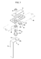
- FIG. 3 is an exploded perspective view of the first terminal side in the rechargeable battery of FIG. 1 .
- the negative electrode lead tab 31 includes a terminal bonding portion 31 b and an electrode assembly bonding portion 31 c that are orthogonally bent.
- the terminal bonding portion 31 b has a terminal hole 31d into which the first terminal 21 is inserted.
- the flange 21 a contacts at a wide area with the terminal bonding portion 31 b.
- the electrode assembly bonding portion 31 c is attached by welding to the negative uncoated region 12a. Thereby, the first terminal 21 is electrically connected to the negative electrode 12 of the electrode assembly 10.
- lower insulation members 41 and 42 are disposed between the negative and positive electrode lead tabs 31 and 32 and the cap plate 28, respectively, and cover a side surface of the negative and positive electrode lead tabs 31 and 32 to electrically insulate the negative and positive electrode lead tabs 31 and 32 and the cap plate 28. Further, the lower insulation members 41 and 42 are disposed between the cap plate 28 and the flanges 21 a and 22a of the first and second terminals 21 and 22 that are positioned at a surface of the negative and positive electrode lead tabs 31 and 32 to electrically insulate the flanges 21 a and 22a and the cap plate 28.
- the rechargeable battery 100 has a short circuit tab 51 and a deformable member 53 between the first and second terminals 21 and 22 in order to short-circuit the positive electrode 11 and the negative electrode 12 when internal pressure rises.
- the deformable member 53 maybe alternatively referred to a short circuit member 53 without limitation since the deformable member 53 establishes a short between the positive and the negative electrodes 11 and 12 upon its deformation.
- the rechargeable battery 100 having the short circuit tab 51 and the deformable member 53 at the first terminal 21 side is exemplified without limitation or restriction.
- the deformable member 53 according to the invention is a one-piece element improving its durability against melting.
- the short circuit tab 51 is electrically connected to the first terminal 21 to be provided to the outside of the cap plate 28.
- An insulation member 37 is disposed between the short circuit tab 51 and the cap plate 28 to electrically insulate the short circuit tab 51 and the cap plate 28. Further, the insulation member 37 is formed in a structure that encloses the side of the short circuit tab 51 to improve insulation safety.
- the first terminal 21 is inserted into the short circuit tab 51 to be electrically connected thereto. By fastening the nut 35 to the screw portion 21 b of the first terminal 21, the short circuit tab 51 and the insulation member 37 are fixed to the first terminal 21 side.
- connection plate 38 electrically connects the second terminal 22 and the cap plate 28.
- the second terminal 22 is inserted into the connection plate 38.
- the connection plate 38 By fastening the nut 45 to the screw portion 22b of the second terminal 22, the connection plate 38 closely contacts the cap plate 28.
- the deformable member 53 When internal pressure of the rechargeable battery 100 rises, the deformable member 53 is deformed to contact the short circuit tab 51 and thus to short-circuit the short circuit tab 51 and the cap plate 28, and is formed to sustain a short-circuited state.
- FIG. 4 is a cross-sectional view illustrating a separation state of a short circuit tab and a deformable member when the rechargeable battery of FIG. 1 normally operates.
- the cap plate 28 in order to install the deformable member 53, the cap plate 28 has a short circuit hole 23.
- the deformable member 53 is disposed between the insulation member 37 and the cap plate 28 at the short circuit hole 23.
- the deformable member 53 has a thin part or film of a curved portion 531 that is formed in an arc shape to be convex inwardly of the case 15, a circumferential edge portion 532 that is formed at the outer side of the curved portion 531 to be electrically connected and fixed to the cap plate 28, and a protruded portion 533 that is protruded to the inside of the case 15 from the center or central region of the curved portion 531.
- the protruded portion 533 may be formed in a thickness of 0.5 to 0.6mm.
- the thickness of the protruded portion 533 is larger than the thickness of its surrounding portions 531, preferably at least 1.2 times larger, even more preferably at least 1.5 times larger.
- the deformable member 53 is formed so that the curved portion 531 together with the protruded portion 533 may be reversed from pointing to pointing upward (see FIG. 5 ).
- FIG. 5 is a cross-sectional view illustrating a contact state of a short circuit tab and a deformable member when internal pressure of the rechargeable battery of FIG. 1 rises.
- the short circuit tab 51 is extended from the first terminal 21 to cover the short circuit hole 23. Therefore, the shape of the deformable member 53 is reversed by the increase of internal pressure of the case 15 to protrude to the outer surface of the cap plate 28 through the short circuit hole 23.
- the deformable member 53 contacts the short circuit tab 51, the short circuit tab 51 and the cap plate 28 are electrically connected (see FIG. 5 ). Thereby, the negative electrode 12 and the positive electrode 11 are short-circuited.
- the protruded portion 533 contacts the short circuit tab 51, when a short circuit occurs, in spite of high heat that is generated between the center of the curved portion 531 and the short circuit tab 51, the protruded portion 533 is not melted and sustains a contact state. That is, as the protruded portion 533 contacts the short circuit tab 51, the protruded portion 533 may be partially melted by heat that is generated when a large current instantaneously flows, but the protruded portion 533 finally continues to sustain a contact state with the short circuit tab 51. Therefore, the negative electrode 12 and the positive electrode 11 continue to sustain a short circuit state. The electrode assembly 10 then no longer performs charge and discharge operations.
- the rechargeable battery 100 When a short circuit state between the negative electrode 12 and the positive electrode 11 is not sustained and internal temperature and pressure rise, the rechargeable battery 100 repeats charge and discharge and may thus explode or ignite, but the protruded portion 533 of the deformable member 53 can prevent explosion and ignition of the rechargeable battery 100.
- FIG. 6 is a cross-sectional view illustrating an operation state of a short circuit tab and a deformable member in a rechargeable battery according to a second exemplary embodiment of the present invention.
- a protruded portion 633 of a deformable member 63 is formed in a structure having a gradually increasing thickness toward the center of a curved portion 631 from a circumferential edge portion 632 (solid line state).
- the thickness in the center is at least 1.2, preferably at least 1.5 times larger than the thickness of the curved portion at is cap plate contact location.
- the deformable member 63 according to the invention is a one-piece element improving its durability against melting.
- the shape of the curved portion 631 of the deformable member 63 is reversed to contact the short circuit tab 51, and the short circuit tab 51 and the cap plate 28 are electrically connected (imaginary line state).
- the protruded portion 633 contacts the short circuit tab 51, when a short circuit occurs, in spite of high heat generated between the center of the curved portion 631 and the short circuit tab 51, the protruded portion 633 is not melted and sustains a contact state.
- the deformable plate is a one-piece member integrally comprising thicker and thinner regions.
Landscapes
- Chemical & Material Sciences (AREA)
- Chemical Kinetics & Catalysis (AREA)
- Electrochemistry (AREA)
- General Chemical & Material Sciences (AREA)
- Engineering & Computer Science (AREA)
- Manufacturing & Machinery (AREA)
- Connection Of Batteries Or Terminals (AREA)
- Sealing Battery Cases Or Jackets (AREA)
- Gas Exhaust Devices For Batteries (AREA)
- Secondary Cells (AREA)
- Cell Separators (AREA)
Abstract
Description
- The present invention relates to a rechargeable battery. More particularly, the present invention relates to a rechargeable battery that relieves and sustains an internal pressure rise state.
- A rechargeable battery can be repeatedly charged and discharged, unlike a primary battery. A small capacity rechargeable battery is used for a small portable electronic device, such as a mobile phone, a laptop computer, and a camcorder, and a large capacity rechargeable battery is used as a power source for driving a motor, such as for a hybrid vehicle.
- A high power rechargeable battery using a high energy density non-aqueous electrolyte has been developed, and such a high power rechargeable battery is formed by coupling a plurality of unit cells in series in order to drive a motor of an appliance, for example an electric vehicle that requires a large amount of electric power.
- A unit cell of the rechargeable battery is formed with a cylindrical shape or a square shape. A square rechargeable battery includes an electrode assembly in which a positive electrode and a negative electrode are positioned with a separator disposed there between, a case that houses the electrode assembly, a cap plate that closes and seals the case and that has a terminal hole, and a terminal that is inserted into the terminal hole and that is electrically connected to the electrode assembly to protrude to the outside of the case.
- If excessive heat occurs at the inside thereof due to charge and discharge operations, or if internal pressure rises due to decomposition of an electrolyte solution, such a rechargeable battery may explode or ignite. It is difficult for a square rechargeable battery to have a structure for intercepting or discharging a current upon overcharge due to particularity of its terminal structure, compared with a cylindrical battery.
-
US 6,342826 B1 discloses a battery with a switch member of bimetal material which operates in response to an elevated temperature, and a foil diaphragm that cooperates with a bumper that operates the switch member in response to an elevated pressure.JP 2006 147180 A JP 5062664 A KR 2006 0020211 - The above information disclosed in this Background section is only for enhancement of understanding of the background of the invention and therefore it may contain information that does not form the prior art that is already known in this country to a person of ordinary skill in the art.
- The present invention has been made in an effort to provide a rechargeable battery having advantages of relieving and sustaining an internal pressure rise state.
- The present invention has been made in an effort to further provide a rechargeable battery having advantages of short-circuiting a positive electrode and a negative electrode and sustaining such a short circuit state, when internal pressure thereof rises.
- Accordingly, a rechargeable battery is provided comprising an electrode assembly having a first electrode, a second electrode, and a separator interposed between the first and the second electrodes, a case for mounting the electrode assembly therein, and a cap assembly. The cap assembly comprises a cap plate for closing an opening of the case, a short circuit tab electrically connected to the first electrode, and a deformable member being in communication with the inside of the battery and having a central portion. The deformable member is placed below the short circuit tab and is adapted to be deformed upon an increase of an internal pressure inside the battery to contact the short circuit tab and to connect the first electrode with the second electrode. The central portion of the deformable member is provided with a greater thickness than the thickness of other parts of the deformable member.
- The central portion of the deformable member is preferably adapted to contact the short circuit tab. Additionally or alternatively, the central portion is formed to have a thickness adapted to sustain contact to the short circuit tab after deformation of the deformable member.
- The deformable member may comprise a circumferential edge portion and a deformable part formed on the inner side of the circumferential edge portion and protruding in convex form toward the interior of the battery.
- The portion of the deformable member is preferably adapted to contact the short circuit tab comprises a protrusion formed to protrude to the inside of the case.
- The protrusion of the deformable member is formed at a central region of the deformable member or deformable part of the deformable member.
- The deformable member is formed in a structure having a gradually increasing thickness form its peripheral region toward its central region.
- The surface of the deformable member facing the interior of the case may be provided with a greater curvature than the surface of the deformable member facing the short circuit tab.
- The deformable member may be formed within or covering or corresponding to a location of a short-circuit hole provided in the cap plate and wherein the short-circuit hole is closed by the deformable member.
- The deformable member is preferably made out of a single piece and made out of conductive material.
- The deformable member may be electrically connected to the second electrode via the cap plate.
- In one embodiment, the short circuit tab has a planar shape.
- The short circuit tab is preferably disposed above the cap plate and above the deformable member. Additionally or alternatively, the short circuit tab may be provided on one side end connected to the first electrode via a first terminal and on the other side end continues beyond the deformable member.
- The cap assembly may further comprise an insulation member such that the short circuit tab is coupled to the cap plate with the insulation member interposed there between to electrically isolate the short circuit tab from the cap plate.
- In one embodiment, the insulation member is formed in a structure enclosing a side of the short circuit tab.
- According to an exemplary embodiment of the present invention, when internal pressure of a rechargeable battery rises, a deformable member contacts a short circuit tab to short-circuit a negative electrode and a positive electrode and thus a large current is formed between the positive electrode and the negative electrode, whereby an electrode assembly is discharged. Thereby, an electrical connection between the terminal and the electrode assembly is intercepted, and rise of an internal pressure is stopped. In this case, the protruded portion of the deformable member is not melted and sustains a contact state with the circuit tab and thus the terminal and the electrode assembly are not again electrically connected. That is, the electrode assembly no longer performs charge and discharge operations.
- Throughout the different embodiments, the deformable plate according to the embodiment is a one-piece member integrally comprising thicker and thinner regions to maintain a short-circuit state after its establishment.
-
-
FIG. 1 is a perspective view illustrating a rechargeable battery according to a first exemplary embodiment of the present invention. -
FIG. 2 is a cross-sectional view illustrating a rechargeable battery taken along line II-II ofFIG. 1 . -
FIG. 3 is an exploded perspective view of the first terminal side in the rechargeable battery ofFIG. 1 . -
FIG. 4 is a cross-sectional view illustrating a separation state of a short circuit tab and a deformable member when the rechargeable battery ofFIG. 1 normally operates. -
FIG. 5 is a cross-sectional view illustrating a contact state of a short circuit tab and a deformable member when internal pressure of the rechargeable battery ofFIG. 1 rises. -
FIG. 6 is a cross-sectional view illustrating a separation state and a contact state of a short circuit tab and a deformable member in a rechargeable battery according to a second exemplary embodiment of the present invention. - The present invention will be described more fully hereinafter with reference to the accompanying drawings, in which exemplary embodiments of the invention are shown. As those skilled in the art would realize, the described embodiments may be modified in various different ways, all without departing from the scope of the present invention. Like reference numerals designate like elements throughout the specification and the drawings.
-
FIG. 1 is a perspective view illustrating a rechargeable battery according to a first exemplary embodiment of the present invention, andFIG. 2 is a cross-sectional view illustrating a rechargeable battery taken along line II-II ofFIG. 1 . Referring toFIGS. 1 and2 , arechargeable battery 100 according to a first exemplary embodiment includes anelectrode assembly 10, acase 15 that houses theelectrode assembly 10, and acap assembly 20 that is coupled to an opening of thecase 15. - The
electrode assembly 10 is preferably formed by spiral-winding apositive electrode 11 and anegative electrode 12, and aseparator 13, which is an insulator that is interposed there between. Further, the electrode assembly may be formed by stacking a plurality of positive electrodes, separators, and negative electrodes that are formed as sheets (not shown). - The
positive electrode 11 and thenegative electrode 12 include a coating region of an area in which an active material is coated on a thin plate of a current collector anduncoated regions uncoated region 11 a of thepositive electrode 11 is formed at one end of thepositive electrode 11 in a length direction of thepositive electrode 11, and theuncoated region 12a of thenegative electrode 12 is formed at the other end of thenegative electrode 12 in a length direction of thenegative electrode 12. - The
case 15 is formed with an approximately cuboid to form a space that houses theelectrode assembly 10 at the inside thereof, and has an opening that is connected to the internal space at one side thereof. - The
cap assembly 20 includes acap plate 28 that covers an opening of thecase 15, and afirst terminal 21 and asecond terminal 22 that are protruded to the outside of thecap plate 28. - The
cap plate 28 is formed with a thin plate and is coupled to the opening of thecase 15. Thecap plate 28 has an electrolyte injection opening 29 and avent hole 24. Aseal stopper 27 is installed at the electrolyte injection opening 29, and avent plate 25 is installed at thevent hole 24. Thevent plate 25 has anotch 25a to be opened when internal pressure of therechargeable battery 100 arrives at a preset pressure. - The
first terminal 21 and thesecond terminal 22 are installed to penetrate through thecap plate 28 to be electrically connected to theelectrode assembly 10 and draw out theelectrode assembly 10 to the outside of thecase 15. That is, thefirst terminal 21 is electrically connected to thenegative electrode 12 of theelectrode assembly 10, and thesecond terminal 22 is electrically connected to thepositive electrode 11. - The
first terminal 21 and thesecond terminal 22 haveflanges case 15 andscrew portions case 15. Byfastening nuts screw portions cap plate 28 from the outside of thecase 15, and theflanges cap plate 28 at the inside of thecase 15. -
Gaskets second terminals cap plate 28 to seal a space between the first andsecond terminals cap plate 28, respectively. - The
first terminal 21 is electrically connected to thenegative electrode 12 by a negativeelectrode lead tab 31, and thesecond terminal 22 is electrically connected to thepositive electrode 11 by a positiveelectrode lead tab 32. The negativeelectrode lead tab 31 and the positiveelectrode lead tab 32 are formed in the same structure, and thus a description regarding the negativeelectrode lead tab 31 is also applicable to the positiveelectrode lead tab 32. -
FIG. 3 is an exploded perspective view of the first terminal side in the rechargeable battery ofFIG. 1 . Referring toFIG. 3 , the negativeelectrode lead tab 31 includes aterminal bonding portion 31 b and an electrodeassembly bonding portion 31 c that are orthogonally bent. - The
terminal bonding portion 31 b has aterminal hole 31d into which thefirst terminal 21 is inserted. When thefirst terminal 21 is inserted into theterminal hole 31d, theflange 21 a contacts at a wide area with theterminal bonding portion 31 b. The electrodeassembly bonding portion 31 c is attached by welding to the negativeuncoated region 12a. Thereby, thefirst terminal 21 is electrically connected to thenegative electrode 12 of theelectrode assembly 10. - Referring again to
FIG. 2 ,lower insulation members electrode lead tabs cap plate 28, respectively, and cover a side surface of the negative and positiveelectrode lead tabs electrode lead tabs cap plate 28. Further, thelower insulation members cap plate 28 and theflanges second terminals electrode lead tabs flanges cap plate 28. - The
rechargeable battery 100 according to an exemplary embodiment has ashort circuit tab 51 and adeformable member 53 between the first andsecond terminals positive electrode 11 and thenegative electrode 12 when internal pressure rises. Thedeformable member 53 maybe alternatively referred to ashort circuit member 53 without limitation since thedeformable member 53 establishes a short between the positive and thenegative electrodes rechargeable battery 100 having theshort circuit tab 51 and thedeformable member 53 at thefirst terminal 21 side is exemplified without limitation or restriction. Thedeformable member 53 according to the invention is a one-piece element improving its durability against melting. - At the
first terminal 21 side, theshort circuit tab 51 is electrically connected to thefirst terminal 21 to be provided to the outside of thecap plate 28. Aninsulation member 37 is disposed between theshort circuit tab 51 and thecap plate 28 to electrically insulate theshort circuit tab 51 and thecap plate 28. Further, theinsulation member 37 is formed in a structure that encloses the side of theshort circuit tab 51 to improve insulation safety. Thefirst terminal 21 is inserted into theshort circuit tab 51 to be electrically connected thereto. By fastening thenut 35 to thescrew portion 21 b of thefirst terminal 21, theshort circuit tab 51 and theinsulation member 37 are fixed to thefirst terminal 21 side. - At the
second terminal 22 side, aconnection plate 38 electrically connects thesecond terminal 22 and thecap plate 28. Thesecond terminal 22 is inserted into theconnection plate 38. By fastening thenut 45 to thescrew portion 22b of thesecond terminal 22, theconnection plate 38 closely contacts thecap plate 28. - When internal pressure of the
rechargeable battery 100 rises, thedeformable member 53 is deformed to contact theshort circuit tab 51 and thus to short-circuit theshort circuit tab 51 and thecap plate 28, and is formed to sustain a short-circuited state. -
FIG. 4 is a cross-sectional view illustrating a separation state of a short circuit tab and a deformable member when the rechargeable battery ofFIG. 1 normally operates. Referring toFIGS. 3 andFIG. 4 , in order to install thedeformable member 53, thecap plate 28 has ashort circuit hole 23. - The
deformable member 53 is disposed between theinsulation member 37 and thecap plate 28 at theshort circuit hole 23. Thedeformable member 53 has a thin part or film of acurved portion 531 that is formed in an arc shape to be convex inwardly of thecase 15, acircumferential edge portion 532 that is formed at the outer side of thecurved portion 531 to be electrically connected and fixed to thecap plate 28, and a protrudedportion 533 that is protruded to the inside of thecase 15 from the center or central region of thecurved portion 531. For example, when thecurved portion 531 is formed in a thickness of 0.4mm, the protrudedportion 533 may be formed in a thickness of 0.5 to 0.6mm. In more general terms, the thickness of the protrudedportion 533 is larger than the thickness of its surroundingportions 531, preferably at least 1.2 times larger, even more preferably at least 1.5 times larger. When internal pressure of thecase 15 rises, thedeformable member 53 is formed so that thecurved portion 531 together with the protrudedportion 533 may be reversed from pointing to pointing upward (seeFIG. 5 ). -
FIG. 5 is a cross-sectional view illustrating a contact state of a short circuit tab and a deformable member when internal pressure of the rechargeable battery ofFIG. 1 rises. Referring toFIG. 5 , theshort circuit tab 51 is extended from thefirst terminal 21 to cover theshort circuit hole 23. Therefore, the shape of thedeformable member 53 is reversed by the increase of internal pressure of thecase 15 to protrude to the outer surface of thecap plate 28 through theshort circuit hole 23. In this case, as thedeformable member 53 contacts theshort circuit tab 51, theshort circuit tab 51 and thecap plate 28 are electrically connected (seeFIG. 5 ). Thereby, thenegative electrode 12 and thepositive electrode 11 are short-circuited. - When a short circuit occurs, as a large current instantaneously flows between the
positive electrode 11 and thenegative electrode 12, theelectrode assembly 10 is discharged. Thereby, an electrical connection is intercepted between the first andsecond terminals electrode assembly 10. - Further, as the protruded
portion 533 contacts theshort circuit tab 51, when a short circuit occurs, in spite of high heat that is generated between the center of thecurved portion 531 and theshort circuit tab 51, the protrudedportion 533 is not melted and sustains a contact state. That is, as the protrudedportion 533 contacts theshort circuit tab 51, the protrudedportion 533 may be partially melted by heat that is generated when a large current instantaneously flows, but the protrudedportion 533 finally continues to sustain a contact state with theshort circuit tab 51. Therefore, thenegative electrode 12 and thepositive electrode 11 continue to sustain a short circuit state. Theelectrode assembly 10 then no longer performs charge and discharge operations. - When a short circuit state between the
negative electrode 12 and thepositive electrode 11 is not sustained and internal temperature and pressure rise, therechargeable battery 100 repeats charge and discharge and may thus explode or ignite, but the protrudedportion 533 of thedeformable member 53 can prevent explosion and ignition of therechargeable battery 100. - Hereinafter, the second exemplary embodiment will be described, but a detailed description of constituent elements identical to or corresponding to those of the first exemplary embodiment will be omitted, and only dissimilar constituent elements will be described in detail.
-
FIG. 6 is a cross-sectional view illustrating an operation state of a short circuit tab and a deformable member in a rechargeable battery according to a second exemplary embodiment of the present invention. Referring toFIG. 6 , in arechargeable battery 200 according to the second exemplary embodiment, a protrudedportion 633 of a deformable member 63 is formed in a structure having a gradually increasing thickness toward the center of acurved portion 631 from a circumferential edge portion 632 (solid line state). Preferably, the thickness in the center is at least 1.2, preferably at least 1.5 times larger than the thickness of the curved portion at is cap plate contact location. The deformable member 63 according to the invention is a one-piece element improving its durability against melting. - When temperature and pressure of the inside of the
rechargeable battery 200 rise, the shape of thecurved portion 631 of the deformable member 63 is reversed to contact theshort circuit tab 51, and theshort circuit tab 51 and thecap plate 28 are electrically connected (imaginary line state). In this case, as the protrudedportion 633 contacts theshort circuit tab 51, when a short circuit occurs, in spite of high heat generated between the center of thecurved portion 631 and theshort circuit tab 51, the protrudedportion 633 is not melted and sustains a contact state. - While this invention has been described in connection with what is presently considered to be practical exemplary embodiments, it is to be understood that the invention is not limited to the disclosed embodiments, but, on the contrary, is intended to cover various modifications and equivalent arrangements included within the scope of the appended claims. Throughout the embodiments, the deformable plate is a one-piece member integrally comprising thicker and thinner regions.
Claims (14)
- A rechargeable battery (100, 200) comprising:an electrode assembly (10) having a first electrode (12), a second electrode (11), and a separator (13) interposed between the first and the second electrodes (12, 11);a case (15) for mounting the electrode assembly (10) therein; anda cap assembly (20) comprising:a cap plate (28) for closing an opening of the case (15),a short circuit tab (51) electrically connected to the first electrode (12), anda deformable member (53) being in communication with the inside of the battery (100, 200) and having a central portion, wherein the deformable member (53) is placed below the short circuit tab (51) and is adapted to be deformed upon an increase of an internal pressure inside the battery (100, 200) to contact the short circuit tab (51) and to connect the first electrode (12) with the second electrode (11),characterized in thatthe central portion of the deformable member (53) is provided with a greater thickness than the thickness of other parts of the deformable member (53).
- Rechargeable battery (100, 200) according to claim 1, wherein the central portion of the deformable member (53) is adapted to contact the short circuit tab and/or is formed to have a thickness adapted to sustain contact to the short circuit tab (51) after deformation of the deformable member (53).
- Rechargeable battery (100, 200) according to any of the previous claims, wherein the deformable member (53) comprises a circumferential edge portion (532, 632) and a deformable part (531, 631) formed on the inner side of the circumferential edge portion (532, 632) and protruding in convex form toward the interior of the battery (100, 200).
- Rechargeable battery (100) according to any of the previous claims, wherein the portion of the deformable member (53) adapted to contact the short circuit tab (51) comprises a protrusion (533) formed to protrude to the inside of the case (15).
- Rechargeable battery (100) according to claim 4, wherein the protrusion (533) of the deformable member (53) is formed at a central region of the deformable member (53) or deformable part (531) of the deformable member (53).
- Rechargeable battery (200) according to any of the previous claims, wherein the deformable member (53) is formed in a structure having a gradually increasing thickness form its peripheral region toward its central region.
- Rechargeable battery (200) of claim 6, wherein the surface of the deformable member (63) facing the interior of the case (15) is provided with a greater curvature than the surface of the deformable member (63) facing the short circuit tab (51).
- Rechargeable battery (100, 200) according to any of the previous claims, wherein the deformable member (53) is formed within or covering or corresponding to a location of a short-circuit hole (23) provided in the cap plate (28) and wherein the short-circuit hole (23) is closed by the deformable member (53).
- Rechargeable battery (100, 200) according to any of the previous claims, wherein the deformable member (53) is made out of a single piece and made out of conductive material.
- Rechargeable battery (100, 200) according to any of the previous claims, wherein the deformable member (53) is electrically connected to the second electrode (11) via the cap plate (28).
- Rechargeable battery (100, 200) according to claim any of the previous claims, wherein the short circuit tab (51) has a planar shape.
- Rechargeable battery (100, 200) according to claim any of the previous claims, wherein the short circuit tab (51)
is disposed above the cap plate (28) and above the deformable member (53), and/or
is on one side end connected to the first electrode (12) via a first terminal (21) and on the other side end continues beyond the deformable member (53). - Rechargeable battery (100, 200) according to any of the previous claims, wherein the cap assembly (20) further comprises an insulation member (37) such that the short circuit tab (51) is coupled to the cap plate (28) with the insulation member (37) interposed therebetween to electrically isolate the short circuit tab (51) from the cap plate (28).
- Rechargeable battery (100, 200) according to claim 13, wherein the insulation member (37) is formed in a structure enclosing a side of the short circuit tab (51).
Applications Claiming Priority (2)
| Application Number | Priority Date | Filing Date | Title |
|---|---|---|---|
| US26779009P | 2009-12-08 | 2009-12-08 | |
| US12/789,114 US8440336B2 (en) | 2009-12-08 | 2010-05-27 | Rechargeable battery with short circuit member |
Publications (2)
| Publication Number | Publication Date |
|---|---|
| EP2333871A1 EP2333871A1 (en) | 2011-06-15 |
| EP2333871B1 true EP2333871B1 (en) | 2012-03-21 |
Family
ID=42396454
Family Applications (1)
| Application Number | Title | Priority Date | Filing Date |
|---|---|---|---|
| EP10168526A Active EP2333871B1 (en) | 2009-12-08 | 2010-07-06 | Rechargeable battery |
Country Status (6)
| Country | Link |
|---|---|
| US (1) | US8440336B2 (en) |
| EP (1) | EP2333871B1 (en) |
| JP (1) | JP5395013B2 (en) |
| KR (1) | KR101191658B1 (en) |
| CN (1) | CN102088103B (en) |
| AT (1) | ATE550793T1 (en) |
Families Citing this family (58)
| Publication number | Priority date | Publication date | Assignee | Title |
|---|---|---|---|---|
| US9246140B2 (en) * | 2009-07-09 | 2016-01-26 | Samsung Sdi Co., Ltd. | Rechargeable battery with a cap assembly having a first tab located outside of the case |
| US8236439B2 (en) * | 2009-08-14 | 2012-08-07 | Sb Limotive Co., Ltd. | Rechargeable battery |
| US8877361B2 (en) * | 2009-09-01 | 2014-11-04 | Samsung Sdi Co., Ltd. | Rechargeable battery |
| KR101113557B1 (en) * | 2009-12-16 | 2012-02-24 | 삼성에스디아이 주식회사 | Secondary battery |
| KR101165514B1 (en) * | 2010-01-27 | 2012-07-16 | 에스비리모티브 주식회사 | Rechargeable battery |
| KR101126809B1 (en) * | 2010-06-16 | 2012-03-23 | 에스비리모티브 주식회사 | Secondary Battery |
| US9478774B2 (en) | 2010-12-02 | 2016-10-25 | Samsung Sdi Co., Ltd. | Rechargeable battery |
| KR101233470B1 (en) * | 2011-01-25 | 2013-02-15 | 로베르트 보쉬 게엠베하 | Rechargeable battery |
| US9023497B2 (en) | 2011-02-18 | 2015-05-05 | Samsung Sdi Co., Ltd. | Secondary battery |
| JP5413394B2 (en) * | 2011-03-28 | 2014-02-12 | 株式会社Gsユアサ | Single cell and battery pack |
| KR101330890B1 (en) * | 2011-04-01 | 2013-11-18 | 도요타지도샤가부시키가이샤 | Power storage device |
| KR101265213B1 (en) | 2011-06-30 | 2013-05-27 | 로베르트 보쉬 게엠베하 | Rechargeable battery with sealing structure |
| US9023498B2 (en) * | 2011-07-07 | 2015-05-05 | Samsung Sdi Co., Ltd. | Rechargeable battery |
| KR101274806B1 (en) | 2011-07-26 | 2013-06-13 | 로베르트 보쉬 게엠베하 | Rechargeable battery |
| US8592079B2 (en) * | 2011-07-28 | 2013-11-26 | Samsung Sdi Co., Ltd. | Rechargeable battery |
| TWM420107U (en) * | 2011-08-22 | 2012-01-01 | Chang Hong Energy Technology Co Ltd | Electrical storage device |
| US9634299B2 (en) | 2011-09-06 | 2017-04-25 | Samsung Sdi Co., Ltd. | Rechargeable battery |
| KR101683210B1 (en) * | 2011-11-17 | 2016-12-07 | 삼성에스디아이 주식회사 | Rechargeable battery |
| KR101696001B1 (en) | 2012-03-23 | 2017-01-12 | 삼성에스디아이 주식회사 | Secondary bttery module |
| KR101715963B1 (en) * | 2012-04-06 | 2017-03-27 | 삼성에스디아이 주식회사 | Secondary bttery |
| KR20140017845A (en) | 2012-08-01 | 2014-02-12 | 삼성에스디아이 주식회사 | Binder for lithium rechargeable battery and electrode for rechargeable battery comprising the same |
| JP2015187913A (en) * | 2012-08-09 | 2015-10-29 | 三洋電機株式会社 | Power supply device, and electrically driven vehicle and power storage device having the same |
| JP5980617B2 (en) * | 2012-08-09 | 2016-08-31 | 三洋電機株式会社 | Non-aqueous electrolyte secondary battery and manufacturing method thereof |
| JP5911772B2 (en) * | 2012-08-09 | 2016-04-27 | 三洋電機株式会社 | Non-aqueous electrolyte secondary battery and manufacturing method thereof |
| CN203038986U (en) * | 2012-11-30 | 2013-07-03 | 宁德新能源科技有限公司 | Power battery safety top cover |
| DE102012222701A1 (en) * | 2012-12-11 | 2014-06-12 | Robert Bosch Gmbh | Memory cell and method for its production |
| KR101666257B1 (en) * | 2013-01-16 | 2016-10-13 | 삼성에스디아이 주식회사 | Rechargeable battery for supressing arc occurance |
| US20140302361A1 (en) * | 2013-04-08 | 2014-10-09 | Samsung Sdi Co., Ltd. | Rechargeable battery |
| DE102013210828A1 (en) * | 2013-06-11 | 2014-12-11 | Robert Bosch Gmbh | Battery cell with short-circuit means for forming a short-circuit current path and method for discharging a battery cell via a short-circuit current path |
| KR101733741B1 (en) * | 2013-10-08 | 2017-05-08 | 삼성에스디아이 주식회사 | Rechargeable battery having connecting member |
| KR101775545B1 (en) | 2013-10-08 | 2017-09-06 | 삼성에스디아이 주식회사 | Rechargeable battery having short protrusion |
| JP5910624B2 (en) * | 2013-12-26 | 2016-04-27 | 株式会社豊田自動織機 | Battery pack |
| DE102014200202A1 (en) * | 2014-01-09 | 2015-07-09 | Robert Bosch Gmbh | Battery cell with overvoltage protection device |
| KR102249889B1 (en) * | 2014-04-07 | 2021-05-07 | 삼성에스디아이 주식회사 | Protection apparutus for rechargeable battery |
| KR102177504B1 (en) * | 2014-04-11 | 2020-11-11 | 삼성에스디아이 주식회사 | Rechargeable battery |
| KR102421778B1 (en) * | 2014-11-14 | 2022-07-14 | 삼성에스디아이 주식회사 | Rechargeable battery charging apparatus |
| KR102299243B1 (en) * | 2015-03-02 | 2021-09-06 | 삼성에스디아이 주식회사 | Rechargeable battery |
| WO2016197375A1 (en) * | 2015-06-11 | 2016-12-15 | 宁德时代新能源科技股份有限公司 | Power battery cap structure and power battery |
| CN204668368U (en) | 2015-06-11 | 2015-09-23 | 宁德时代新能源科技有限公司 | Top cover structure of power battery and electrokinetic cell |
| US10763487B2 (en) | 2015-07-23 | 2020-09-01 | Contemporary Amperex Technology Co., Limited | Power battery cap structure and power battery |
| CN106935740B (en) * | 2015-07-23 | 2019-12-20 | 宁德时代新能源科技股份有限公司 | Power battery top cover structure and power battery |
| EP3390134A4 (en) | 2015-12-14 | 2019-05-15 | Cadenza Innovation, Inc. | LOW PROFILE PRESSURE DISCONNECT DEVICE FOR LITHIUM ION BATTERIES |
| TWI569495B (en) * | 2015-12-25 | 2017-02-01 | 財團法人工業技術研究院 | Actuating structure of battery safety valve |
| JP6380420B2 (en) * | 2016-02-04 | 2018-08-29 | トヨタ自動車株式会社 | Secondary battery and battery pack |
| JP6631835B2 (en) * | 2016-03-22 | 2020-01-15 | トヨタ自動車株式会社 | Rechargeable battery |
| KR102612060B1 (en) * | 2016-04-26 | 2023-12-07 | 삼성에스디아이 주식회사 | Rechargeable battery having membrane |
| CN106450063B (en) | 2016-11-15 | 2019-07-19 | 宁德时代新能源科技股份有限公司 | Secondary battery |
| CN108075055B (en) | 2016-11-16 | 2021-05-07 | 宁德时代新能源科技股份有限公司 | Power battery top cover structure and power battery |
| EP3544090B1 (en) * | 2016-12-02 | 2020-12-16 | Contemporary Amperex Technology Co., Limited | Top cover assembly for power battery and power battery having the same |
| CN107369788B (en) * | 2017-06-20 | 2020-05-05 | 宁德时代新能源科技股份有限公司 | A power battery top cover assembly, power battery and battery module |
| DE102017214242A1 (en) * | 2017-08-16 | 2019-02-21 | Robert Bosch Gmbh | Battery cell, battery module and method of making such |
| KR20200111498A (en) * | 2019-03-19 | 2020-09-29 | 삼성에스디아이 주식회사 | Secondary Battery |
| CN111029489B (en) | 2019-08-14 | 2021-08-17 | 宁德时代新能源科技股份有限公司 | Secondary battery |
| CN111029488B (en) | 2019-08-14 | 2021-07-30 | 宁德时代新能源科技股份有限公司 | Secondary battery |
| KR102598914B1 (en) * | 2021-09-28 | 2023-11-03 | 컨템포러리 엠퍼렉스 테크놀로지 씨오., 리미티드 | Floating nut assembly and electrical equipment |
| JP7613452B2 (en) * | 2022-11-10 | 2025-01-15 | トヨタ自動車株式会社 | Energy storage cell |
| CN119674357B (en) * | 2024-12-24 | 2025-09-19 | 蜂巢能源科技股份有限公司 | Battery cell shell and battery cell |
| CN119674359B (en) * | 2024-12-24 | 2025-09-23 | 蜂巢能源科技股份有限公司 | Battery cell and battery module |
Family Cites Families (12)
| Publication number | Priority date | Publication date | Assignee | Title |
|---|---|---|---|---|
| JPH0562664A (en) | 1991-09-02 | 1993-03-12 | Matsushita Electric Ind Co Ltd | Explosion-proof non-aqueous secondary battery |
| US5523178A (en) * | 1992-12-14 | 1996-06-04 | Nippondenso Co., Ltd. | Chemical cell |
| JP3573293B2 (en) * | 1993-11-24 | 2004-10-06 | 日本電池株式会社 | battery |
| US6342826B1 (en) * | 1999-08-11 | 2002-01-29 | Therm-O-Disc, Incorporated | Pressure and temperature responsive switch assembly |
| KR100599748B1 (en) * | 2004-06-23 | 2006-07-12 | 삼성에스디아이 주식회사 | Cap assembly of secondary battery and secondary battery and safety valve installation method |
| JP2006012831A (en) * | 2004-06-23 | 2006-01-12 | Samsung Sdi Co Ltd | Secondary battery, secondary battery cap assembly, and secondary battery safety valve mounting method |
| KR100619631B1 (en) | 2004-08-31 | 2006-09-12 | 주식회사 엘지화학 | Improved Lithium Secondary Battery |
| JP2006147180A (en) | 2004-11-16 | 2006-06-08 | Toshiba Corp | Nonaqueous electrolyte secondary battery |
| KR100614376B1 (en) * | 2005-04-25 | 2006-08-22 | 삼성에스디아이 주식회사 | Can-type Lithium Secondary Battery |
| KR100880321B1 (en) * | 2006-12-14 | 2009-01-28 | 삼성에스디아이 주식회사 | Secondary battery |
| US9246140B2 (en) * | 2009-07-09 | 2016-01-26 | Samsung Sdi Co., Ltd. | Rechargeable battery with a cap assembly having a first tab located outside of the case |
| US8236439B2 (en) * | 2009-08-14 | 2012-08-07 | Sb Limotive Co., Ltd. | Rechargeable battery |
-
2010
- 2010-05-27 US US12/789,114 patent/US8440336B2/en active Active
- 2010-06-29 KR KR1020100062270A patent/KR101191658B1/en active Active
- 2010-07-06 EP EP10168526A patent/EP2333871B1/en active Active
- 2010-07-06 AT AT10168526T patent/ATE550793T1/en active
- 2010-07-21 CN CN201010235577.2A patent/CN102088103B/en active Active
- 2010-08-24 JP JP2010187474A patent/JP5395013B2/en active Active
Also Published As
| Publication number | Publication date |
|---|---|
| CN102088103B (en) | 2014-06-04 |
| KR101191658B1 (en) | 2012-10-17 |
| KR20110065277A (en) | 2011-06-15 |
| JP2011124214A (en) | 2011-06-23 |
| ATE550793T1 (en) | 2012-04-15 |
| US8440336B2 (en) | 2013-05-14 |
| JP5395013B2 (en) | 2014-01-22 |
| EP2333871A1 (en) | 2011-06-15 |
| CN102088103A (en) | 2011-06-08 |
| US20110135976A1 (en) | 2011-06-09 |
Similar Documents
| Publication | Publication Date | Title |
|---|---|---|
| EP2333871B1 (en) | Rechargeable battery | |
| KR101182284B1 (en) | Rechargeable battery | |
| US8877361B2 (en) | Rechargeable battery | |
| EP2357685B1 (en) | Rechargeable battery | |
| US9172079B2 (en) | Rechargeable battery | |
| EP2273587B1 (en) | Rechargeable battery | |
| EP2348558B1 (en) | Rechargeable battery | |
| EP2461393B1 (en) | Rechargeable Battery | |
| US8435659B2 (en) | Rechargeable battery | |
| EP2595214B1 (en) | Rechargeable battery | |
| KR101744090B1 (en) | Rechargeable battery having short member | |
| KR20140124247A (en) | Rechargeable battery | |
| US8133602B2 (en) | Rechargeable battery | |
| EP2330660B1 (en) | Rechargeable battery |
Legal Events
| Date | Code | Title | Description |
|---|---|---|---|
| PUAI | Public reference made under article 153(3) epc to a published international application that has entered the european phase |
Free format text: ORIGINAL CODE: 0009012 |
|
| 17P | Request for examination filed |
Effective date: 20100706 |
|
| AK | Designated contracting states |
Kind code of ref document: A1 Designated state(s): AL AT BE BG CH CY CZ DE DK EE ES FI FR GB GR HR HU IE IS IT LI LT LU LV MC MK MT NL NO PL PT RO SE SI SK SM TR |
|
| AX | Request for extension of the european patent |
Extension state: BA ME RS |
|
| RIC1 | Information provided on ipc code assigned before grant |
Ipc: H01M 10/42 20060101ALI20110707BHEP Ipc: H01M 2/12 20060101ALI20110707BHEP Ipc: H01M 2/34 20060101ALI20110707BHEP Ipc: H01M 2/08 20060101ALI20110707BHEP Ipc: H01M 2/04 20060101AFI20110707BHEP |
|
| GRAP | Despatch of communication of intention to grant a patent |
Free format text: ORIGINAL CODE: EPIDOSNIGR1 |
|
| GRAS | Grant fee paid |
Free format text: ORIGINAL CODE: EPIDOSNIGR3 |
|
| GRAA | (expected) grant |
Free format text: ORIGINAL CODE: 0009210 |
|
| AK | Designated contracting states |
Kind code of ref document: B1 Designated state(s): AL AT BE BG CH CY CZ DE DK EE ES FI FR GB GR HR HU IE IS IT LI LT LU LV MC MK MT NL NO PL PT RO SE SI SK SM TR |
|
| REG | Reference to a national code |
Ref country code: GB Ref legal event code: FG4D |
|
| REG | Reference to a national code |
Ref country code: CH Ref legal event code: EP |
|
| REG | Reference to a national code |
Ref country code: IE Ref legal event code: FG4D |
|
| REG | Reference to a national code |
Ref country code: AT Ref legal event code: REF Ref document number: 550793 Country of ref document: AT Kind code of ref document: T Effective date: 20120415 |
|
| REG | Reference to a national code |
Ref country code: DE Ref legal event code: R096 Ref document number: 602010001096 Country of ref document: DE Effective date: 20120516 |
|
| REG | Reference to a national code |
Ref country code: NL Ref legal event code: VDEP Effective date: 20120321 |
|
| PG25 | Lapsed in a contracting state [announced via postgrant information from national office to epo] |
Ref country code: LT Free format text: LAPSE BECAUSE OF FAILURE TO SUBMIT A TRANSLATION OF THE DESCRIPTION OR TO PAY THE FEE WITHIN THE PRESCRIBED TIME-LIMIT Effective date: 20120321 Ref country code: HR Free format text: LAPSE BECAUSE OF FAILURE TO SUBMIT A TRANSLATION OF THE DESCRIPTION OR TO PAY THE FEE WITHIN THE PRESCRIBED TIME-LIMIT Effective date: 20120321 Ref country code: NO Free format text: LAPSE BECAUSE OF FAILURE TO SUBMIT A TRANSLATION OF THE DESCRIPTION OR TO PAY THE FEE WITHIN THE PRESCRIBED TIME-LIMIT Effective date: 20120621 |
|
| LTIE | Lt: invalidation of european patent or patent extension |
Effective date: 20120321 |
|
| PG25 | Lapsed in a contracting state [announced via postgrant information from national office to epo] |
Ref country code: GR Free format text: LAPSE BECAUSE OF FAILURE TO SUBMIT A TRANSLATION OF THE DESCRIPTION OR TO PAY THE FEE WITHIN THE PRESCRIBED TIME-LIMIT Effective date: 20120622 Ref country code: LV Free format text: LAPSE BECAUSE OF FAILURE TO SUBMIT A TRANSLATION OF THE DESCRIPTION OR TO PAY THE FEE WITHIN THE PRESCRIBED TIME-LIMIT Effective date: 20120321 Ref country code: FI Free format text: LAPSE BECAUSE OF FAILURE TO SUBMIT A TRANSLATION OF THE DESCRIPTION OR TO PAY THE FEE WITHIN THE PRESCRIBED TIME-LIMIT Effective date: 20120321 |
|
| REG | Reference to a national code |
Ref country code: AT Ref legal event code: MK05 Ref document number: 550793 Country of ref document: AT Kind code of ref document: T Effective date: 20120321 |
|
| PG25 | Lapsed in a contracting state [announced via postgrant information from national office to epo] |
Ref country code: CY Free format text: LAPSE BECAUSE OF FAILURE TO SUBMIT A TRANSLATION OF THE DESCRIPTION OR TO PAY THE FEE WITHIN THE PRESCRIBED TIME-LIMIT Effective date: 20120321 |
|
| PG25 | Lapsed in a contracting state [announced via postgrant information from national office to epo] |
Ref country code: RO Free format text: LAPSE BECAUSE OF FAILURE TO SUBMIT A TRANSLATION OF THE DESCRIPTION OR TO PAY THE FEE WITHIN THE PRESCRIBED TIME-LIMIT Effective date: 20120321 Ref country code: BE Free format text: LAPSE BECAUSE OF FAILURE TO SUBMIT A TRANSLATION OF THE DESCRIPTION OR TO PAY THE FEE WITHIN THE PRESCRIBED TIME-LIMIT Effective date: 20120321 Ref country code: PL Free format text: LAPSE BECAUSE OF FAILURE TO SUBMIT A TRANSLATION OF THE DESCRIPTION OR TO PAY THE FEE WITHIN THE PRESCRIBED TIME-LIMIT Effective date: 20120321 Ref country code: CZ Free format text: LAPSE BECAUSE OF FAILURE TO SUBMIT A TRANSLATION OF THE DESCRIPTION OR TO PAY THE FEE WITHIN THE PRESCRIBED TIME-LIMIT Effective date: 20120321 Ref country code: IS Free format text: LAPSE BECAUSE OF FAILURE TO SUBMIT A TRANSLATION OF THE DESCRIPTION OR TO PAY THE FEE WITHIN THE PRESCRIBED TIME-LIMIT Effective date: 20120721 Ref country code: SE Free format text: LAPSE BECAUSE OF FAILURE TO SUBMIT A TRANSLATION OF THE DESCRIPTION OR TO PAY THE FEE WITHIN THE PRESCRIBED TIME-LIMIT Effective date: 20120321 Ref country code: SI Free format text: LAPSE BECAUSE OF FAILURE TO SUBMIT A TRANSLATION OF THE DESCRIPTION OR TO PAY THE FEE WITHIN THE PRESCRIBED TIME-LIMIT Effective date: 20120321 Ref country code: EE Free format text: LAPSE BECAUSE OF FAILURE TO SUBMIT A TRANSLATION OF THE DESCRIPTION OR TO PAY THE FEE WITHIN THE PRESCRIBED TIME-LIMIT Effective date: 20120321 |
|
| PG25 | Lapsed in a contracting state [announced via postgrant information from national office to epo] |
Ref country code: SK Free format text: LAPSE BECAUSE OF FAILURE TO SUBMIT A TRANSLATION OF THE DESCRIPTION OR TO PAY THE FEE WITHIN THE PRESCRIBED TIME-LIMIT Effective date: 20120321 Ref country code: PT Free format text: LAPSE BECAUSE OF FAILURE TO SUBMIT A TRANSLATION OF THE DESCRIPTION OR TO PAY THE FEE WITHIN THE PRESCRIBED TIME-LIMIT Effective date: 20120723 |
|
| PLBE | No opposition filed within time limit |
Free format text: ORIGINAL CODE: 0009261 |
|
| STAA | Information on the status of an ep patent application or granted ep patent |
Free format text: STATUS: NO OPPOSITION FILED WITHIN TIME LIMIT |
|
| PG25 | Lapsed in a contracting state [announced via postgrant information from national office to epo] |
Ref country code: AT Free format text: LAPSE BECAUSE OF FAILURE TO SUBMIT A TRANSLATION OF THE DESCRIPTION OR TO PAY THE FEE WITHIN THE PRESCRIBED TIME-LIMIT Effective date: 20120321 Ref country code: DK Free format text: LAPSE BECAUSE OF FAILURE TO SUBMIT A TRANSLATION OF THE DESCRIPTION OR TO PAY THE FEE WITHIN THE PRESCRIBED TIME-LIMIT Effective date: 20120321 Ref country code: NL Free format text: LAPSE BECAUSE OF FAILURE TO SUBMIT A TRANSLATION OF THE DESCRIPTION OR TO PAY THE FEE WITHIN THE PRESCRIBED TIME-LIMIT Effective date: 20120321 |
|
| 26N | No opposition filed |
Effective date: 20130102 |
|
| PG25 | Lapsed in a contracting state [announced via postgrant information from national office to epo] |
Ref country code: MK Free format text: LAPSE BECAUSE OF FAILURE TO SUBMIT A TRANSLATION OF THE DESCRIPTION OR TO PAY THE FEE WITHIN THE PRESCRIBED TIME-LIMIT Effective date: 20120321 Ref country code: IT Free format text: LAPSE BECAUSE OF FAILURE TO SUBMIT A TRANSLATION OF THE DESCRIPTION OR TO PAY THE FEE WITHIN THE PRESCRIBED TIME-LIMIT Effective date: 20120321 Ref country code: MC Free format text: LAPSE BECAUSE OF NON-PAYMENT OF DUE FEES Effective date: 20120731 |
|
| REG | Reference to a national code |
Ref country code: FR Ref legal event code: TQ Owner name: SAMSUNG SDI CO., LTD., KR Effective date: 20130218 Ref country code: FR Ref legal event code: TQ Owner name: ROBERT BOSCH GMBH, DE Effective date: 20130218 |
|
| REG | Reference to a national code |
Ref country code: DE Ref legal event code: R082 Ref document number: 602010001096 Country of ref document: DE Representative=s name: GULDE HENGELHAUPT ZIEBIG & SCHNEIDER, DE Effective date: 20130221 Ref country code: DE Ref legal event code: R081 Ref document number: 602010001096 Country of ref document: DE Owner name: ROBERT BOSCH GMBH, DE Free format text: FORMER OWNER: SB LIMOTIVE CO., LTD., YONGIN, KR Effective date: 20130221 Ref country code: DE Ref legal event code: R081 Ref document number: 602010001096 Country of ref document: DE Owner name: SAMSUNG SDI CO., LTD., KR Free format text: FORMER OWNER: SB LIMOTIVE CO., LTD., YONGIN, KR Effective date: 20130221 Ref country code: DE Ref legal event code: R081 Ref document number: 602010001096 Country of ref document: DE Owner name: ROBERT BOSCH GMBH, DE Free format text: FORMER OWNER: SB LIMOTIVE CO., LTD., YONGIN, KYONGGI, KR Effective date: 20130221 Ref country code: DE Ref legal event code: R082 Ref document number: 602010001096 Country of ref document: DE Representative=s name: GULDE & PARTNER PATENT- UND RECHTSANWALTSKANZL, DE Effective date: 20130221 Ref country code: DE Ref legal event code: R081 Ref document number: 602010001096 Country of ref document: DE Owner name: SAMSUNG SDI CO., LTD., YONGIN, KR Free format text: FORMER OWNER: SB LIMOTIVE CO., LTD., YONGIN, KYONGGI, KR Effective date: 20130221 Ref country code: DE Ref legal event code: R097 Ref document number: 602010001096 Country of ref document: DE Effective date: 20130102 |
|
| PG25 | Lapsed in a contracting state [announced via postgrant information from national office to epo] |
Ref country code: ES Free format text: LAPSE BECAUSE OF FAILURE TO SUBMIT A TRANSLATION OF THE DESCRIPTION OR TO PAY THE FEE WITHIN THE PRESCRIBED TIME-LIMIT Effective date: 20120702 |
|
| REG | Reference to a national code |
Ref country code: IE Ref legal event code: MM4A |
|
| REG | Reference to a national code |
Ref country code: GB Ref legal event code: 732E Free format text: REGISTERED BETWEEN 20130418 AND 20130424 |
|
| PG25 | Lapsed in a contracting state [announced via postgrant information from national office to epo] |
Ref country code: MT Free format text: LAPSE BECAUSE OF FAILURE TO SUBMIT A TRANSLATION OF THE DESCRIPTION OR TO PAY THE FEE WITHIN THE PRESCRIBED TIME-LIMIT Effective date: 20120321 Ref country code: BG Free format text: LAPSE BECAUSE OF FAILURE TO SUBMIT A TRANSLATION OF THE DESCRIPTION OR TO PAY THE FEE WITHIN THE PRESCRIBED TIME-LIMIT Effective date: 20120621 Ref country code: IE Free format text: LAPSE BECAUSE OF NON-PAYMENT OF DUE FEES Effective date: 20120706 |
|
| PG25 | Lapsed in a contracting state [announced via postgrant information from national office to epo] |
Ref country code: AL Free format text: LAPSE BECAUSE OF FAILURE TO SUBMIT A TRANSLATION OF THE DESCRIPTION OR TO PAY THE FEE WITHIN THE PRESCRIBED TIME-LIMIT Effective date: 20120321 |
|
| PG25 | Lapsed in a contracting state [announced via postgrant information from national office to epo] |
Ref country code: TR Free format text: LAPSE BECAUSE OF FAILURE TO SUBMIT A TRANSLATION OF THE DESCRIPTION OR TO PAY THE FEE WITHIN THE PRESCRIBED TIME-LIMIT Effective date: 20120321 |
|
| PG25 | Lapsed in a contracting state [announced via postgrant information from national office to epo] |
Ref country code: LU Free format text: LAPSE BECAUSE OF NON-PAYMENT OF DUE FEES Effective date: 20120706 Ref country code: SM Free format text: LAPSE BECAUSE OF FAILURE TO SUBMIT A TRANSLATION OF THE DESCRIPTION OR TO PAY THE FEE WITHIN THE PRESCRIBED TIME-LIMIT Effective date: 20120321 |
|
| PG25 | Lapsed in a contracting state [announced via postgrant information from national office to epo] |
Ref country code: HU Free format text: LAPSE BECAUSE OF FAILURE TO SUBMIT A TRANSLATION OF THE DESCRIPTION OR TO PAY THE FEE WITHIN THE PRESCRIBED TIME-LIMIT Effective date: 20100706 |
|
| REG | Reference to a national code |
Ref country code: CH Ref legal event code: PL |
|
| PG25 | Lapsed in a contracting state [announced via postgrant information from national office to epo] |
Ref country code: LI Free format text: LAPSE BECAUSE OF NON-PAYMENT OF DUE FEES Effective date: 20140731 Ref country code: CH Free format text: LAPSE BECAUSE OF NON-PAYMENT OF DUE FEES Effective date: 20140731 |
|
| REG | Reference to a national code |
Ref country code: FR Ref legal event code: PLFP Year of fee payment: 7 |
|
| REG | Reference to a national code |
Ref country code: FR Ref legal event code: PLFP Year of fee payment: 8 |
|
| REG | Reference to a national code |
Ref country code: FR Ref legal event code: PLFP Year of fee payment: 9 |
|
| REG | Reference to a national code |
Ref country code: DE Ref legal event code: R079 Ref document number: 602010001096 Country of ref document: DE Free format text: PREVIOUS MAIN CLASS: H01M0002040000 Ipc: H01M0050147000 |
|
| P01 | Opt-out of the competence of the unified patent court (upc) registered |
Effective date: 20230528 |
|
| PGFP | Annual fee paid to national office [announced via postgrant information from national office to epo] |
Ref country code: GB Payment date: 20250626 Year of fee payment: 16 |
|
| PGFP | Annual fee paid to national office [announced via postgrant information from national office to epo] |
Ref country code: FR Payment date: 20250623 Year of fee payment: 16 |
|
| PGFP | Annual fee paid to national office [announced via postgrant information from national office to epo] |
Ref country code: DE Payment date: 20250624 Year of fee payment: 16 |