EP2333783B1 - Apparatus for removing a thermal sleeve from a cold leg of a reactor cooling system - Google Patents
Apparatus for removing a thermal sleeve from a cold leg of a reactor cooling system Download PDFInfo
- Publication number
- EP2333783B1 EP2333783B1 EP10156577.8A EP10156577A EP2333783B1 EP 2333783 B1 EP2333783 B1 EP 2333783B1 EP 10156577 A EP10156577 A EP 10156577A EP 2333783 B1 EP2333783 B1 EP 2333783B1
- Authority
- EP
- European Patent Office
- Prior art keywords
- movement carrier
- sleeve
- removal tool
- pipe
- safety injection
- Prior art date
- Legal status (The legal status is an assumption and is not a legal conclusion. Google has not performed a legal analysis and makes no representation as to the accuracy of the status listed.)
- Active
Links
Images





Classifications
-
- G—PHYSICS
- G21—NUCLEAR PHYSICS; NUCLEAR ENGINEERING
- G21C—NUCLEAR REACTORS
- G21C17/00—Monitoring; Testing ; Maintaining
- G21C17/017—Inspection or maintenance of pipe-lines or tubes in nuclear installations
-
- G—PHYSICS
- G21—NUCLEAR PHYSICS; NUCLEAR ENGINEERING
- G21C—NUCLEAR REACTORS
- G21C15/00—Cooling arrangements within the pressure vessel containing the core; Selection of specific coolants
- G21C15/18—Emergency cooling arrangements; Removing shut-down heat
-
- G—PHYSICS
- G21—NUCLEAR PHYSICS; NUCLEAR ENGINEERING
- G21C—NUCLEAR REACTORS
- G21C13/00—Pressure vessels; Containment vessels; Containment in general
- G21C13/02—Details
- G21C13/032—Joints between tubes and vessel walls, e.g. taking into account thermal stresses
-
- G—PHYSICS
- G21—NUCLEAR PHYSICS; NUCLEAR ENGINEERING
- G21C—NUCLEAR REACTORS
- G21C19/00—Arrangements for treating, for handling, or for facilitating the handling of, fuel or other materials which are used within the reactor, e.g. within its pressure vessel
- G21C19/16—Articulated or telescopic chutes or tubes for connection to channels in the reactor core
-
- G—PHYSICS
- G21—NUCLEAR PHYSICS; NUCLEAR ENGINEERING
- G21C—NUCLEAR REACTORS
- G21C19/00—Arrangements for treating, for handling, or for facilitating the handling of, fuel or other materials which are used within the reactor, e.g. within its pressure vessel
- G21C19/20—Arrangements for introducing objects into the pressure vessel; Arrangements for handling objects within the pressure vessel; Arrangements for removing objects from the pressure vessel
- G21C19/207—Assembling, maintenance or repair of reactor components
-
- Y—GENERAL TAGGING OF NEW TECHNOLOGICAL DEVELOPMENTS; GENERAL TAGGING OF CROSS-SECTIONAL TECHNOLOGIES SPANNING OVER SEVERAL SECTIONS OF THE IPC; TECHNICAL SUBJECTS COVERED BY FORMER USPC CROSS-REFERENCE ART COLLECTIONS [XRACs] AND DIGESTS
- Y02—TECHNOLOGIES OR APPLICATIONS FOR MITIGATION OR ADAPTATION AGAINST CLIMATE CHANGE
- Y02E—REDUCTION OF GREENHOUSE GAS [GHG] EMISSIONS, RELATED TO ENERGY GENERATION, TRANSMISSION OR DISTRIBUTION
- Y02E30/00—Energy generation of nuclear origin
- Y02E30/30—Nuclear fission reactors
Definitions
- the present invention relates to an apparatus for effectively removing a thermal sleeve from a reactor coolant system when the thermal sleeve is unintentionally separated from the system.
- a reactor coolant system incorporates a safety injection pipe to supply safety injection water, in order to assure cooling of a reactor core in the event of an emergency situation.
- the safety injection pipe is provided with a thermal sleeve at a junction of the safety injection pipe and a reactor coolant pipe to minimize the effect of thermal shock of a hot reactor coolant and cold safety injection water on the pipes.
- the thermal sleeve installed as described above, may undergo unintentional separation or position displacement due to fluid streams, external vibration, or the like in the course of operation. Once the thermal sleeve is unintentionally separated, it is necessary to effectively remove the separated thermal sleeve so as not to have a negative effect on the operation of a power plant.
- thermal sleeve is located in a highly radioactive region close to a nuclear reactor and is filled with a boric acid solution for radiation shielding, it is actually impossible for a person to access the thermal sleeve.
- a safety injection pipe is first cut and thereafter, a thermal sleeve is removed by use of cutting equipment.
- implementation of such a cutting operation may disadvantageously increase a removal operation period and also, may entail problems including reliability deterioration due to cutting and repetitious welding of a major system, enormous removal costs, invasion of impurities, and the like.
- Document KR 2006 0054498 A discloses a further method for removing a thermal sleeve from a cold leg of a reactor coolant system, which method comprises cutting operations.
- Document US 2004/028169 A1 discloses an apparatus which is suitable for removing a thermal sleeve from a cold leg of a reactor coolant system.
- This apparatus comprises a horizontal and a vertical movement carrier and a seating rod into which a the tool is seated and coupled.
- This apparatus comprises a sleeve removal tool and a horizontal movement carrier.
- the present invention has been made to solve the above problems of the previously described conventional thermal sleeve removal method in which cutting of a safety injection pipe is carried out ahead of removal of a thermal sleeve, and it is an object of the present invention to provide an apparatus capable of easily removing a thermal sleeve without performing a pipe cutting operation, thereby improving workability and system reliability.
- an apparatus for removing a thermal sleeve installed at a junction between a coolant pipe of a reactor and a safety injection pipe connected to a midway position of the coolant pipe including a sleeve removal tool including a corn head formed at a front end of a shaft having a predetermined length, a pressure plate provided below the corn head and divided into a plurality of sections so as to be folded or unfolded, and a spring connected to an upper surface of the pressure plate to keep the pressure plate in an unfolded state, a horizontal movement carrier including a plurality of bodies connected to each other by use of a link, a seating rod into which the sleeve removal tool is seated and coupled, and moving wheels installed to the respective bodies for movement of the horizontal movement carrier, and a vertical movement carrier including first and second anti-separation bars provided respectively at front and rear ends thereof to prevent the horizontal movement carrier from being separated from the vertical movement carrier during upward or
- a slider ring may be movably installed to the shaft of the sleeve removal tool, and a tension release link may be provided to connect the pressure plate and the slider ring to each other.
- An introduction eyebolt for connection of an introduction wire rope may be installed at the front end of the shaft of the sleeve removal tool, and a pulling eyebolt for connection of a pulling wire rope may be installed at a rear end of the shaft.
- the thermal sleeve removal apparatus includes a sleeve removal tool 10 to forcibly remove a thermal sleeve 1 installed in a safety injection pipe 120, a horizontal movement carrier 20 to transport the sleeve removal tool 10 along a coolant pipe 110 via horizontal sliding movement thereof, and a vertical movement carrier 30 to move the horizontal movement carrier 20 up and down within a reactor 100, and an extension pipe 40 connected to a check valve removal position of the safety injection pipe 120 so as to guide a wire rope W and a cable for handling of the sleeve removal tool 10 and the horizontal movement carrier 20.
- the sleeve removal tool 10 includes a corn head 12 and an introduction eyebolt 13 provided at a front end of a shaft 11, a pulling eyebolt 14 provided at a rear end of the shaft 11, and a guide wheel 15 provided at an approximately middle position of the shaft 11 to guide insertion of the sleeve removal tool 10 into the safety injection pipe 120.
- a pressure plate 16 is provided below the corn head 12 to maximize the effect of hydraulic pressure inside the safety injection pipe 120.
- the pressure plate 16 has a foldable form and is divided into a plurality of sections.
- a spring 17 is connected to an upper surface of the pressure plate 16 to apply an elastic force to the pressure plate 16.
- One end of a tension release link 18 is connected to a lower surface of the pressure plate 16 to release a tensile force applied to the pressure plate 16, and the other end of the tension release link 18 is connected to a slider ring 19 that can slide along the shaft 11.
- the slider ring 19 be provided with a wire connection loop 19a for connection of a wire rope used to forcibly release the tensile force applied to the pressure plate 16.
- the horizontal movement carrier 20 as shown in FIGS. 3A to 3C , consists of two bodies 21 connected to each other by use of a link 22.
- the two bodies 21 have cutout edges 21a facing each other to define a space therebetween so that the bodies 21 can be tilted toward or away from each other by a predetermined inclination angle.
- a seating rod 23 is provided at a rear end of the horizontal movement carrier 20 so that the shaft 11 of the sleeve removal tool 10 can be inserted into and seated in the seating rod 23.
- moving wheels 24 are mounted to the bottom and sidewalls of the respective bodies 21.
- Reference numeral 25 represents a wire connection loop provided for connection of wire ropes W and W'.
- the wire connection loop 25 may be provided at the same position as the seating rod 23 for the insertion and seating of the sleeve removal tool 10. This may assure the sleeve removal tool 10 to be accurately positioned at an entrance of the safety injection pipe 120 via sliding movement of the horizontal movement carrier 20.
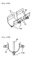
- the vertical movement carrier 30, as shown in FIGS. 4A to 4C includes a first anti-separation bar 31 provided at a rear end thereof to prevent separation of the horizontal movement carrier 20, a second anti-separation bar 32 pivotally coupled to a front end thereof by use of a hinge 32a, and a guiding floor 33 protruding forward from the bottom thereof.
- Reference numeral 35 represents a wire connection loop for connection of a wire rope used to ascend or descend the vertical movement carrier 30.
- the extension pipe 40 as shown in FIGS. 5A and 5B , has a bent lower end portion 41 obliquely extending by a predetermined guidance angle to allow an initially inserted cable to move toward the coolant pipe 110.
- a core support barrel (CSB) is reinstalled in a cavity of the reactor 100 and then, the level of a fluid inside the cavity of the reactor 100 is lowered from 140 ft to 110 ft, causing the safety injection pipe 120 to be exposed.
- a check valve (not shown) provided at the safety injection pipe 120 is disassembled to remove an element accommodated in the safety injection pipe 120 and thereafter, the extension pipe 40 having a predetermined length is connected to the safety injection pipe 120.
- the cavity of the reactor in which the core support barrel as a highly radioactive object is accommodated, is always filled with a boric acid solution to prevent the core support barrel from being exposed to the atmosphere.
- the boric acid solution is charged to the level of 140 ft
- the thermal sleeve 1 is located at a height of approximately 105 ft
- the check valve (not shown) of the safety injection pipe 120 is typically located at a height of 110 ft.
- a worker in a primary working zone A provided at an upper end of the reactor 100 is able to grip and lift the cable by use of a nipper.
- the sleeve removal tool 10, the horizontal movement carrier 20 and the vertical movement carrier 30, which constitute the removal apparatus of the present invention, are initially placed on the primary working zone A provided at the upper end of the reactor 100.
- one ends of the wire ropes W are connected respectively to one side of the respective devices (i.e. the sleeve removal tool 10, the horizontal movement carrier 20, and the vertical movement carrier 30) for movement and installation of the devices, and additional pulling wire ropes W' are connected to the other side of the respective devices.
- the vertical movement carrier 30 is guided to slowly descend inside the reactor 100.
- the vertical movement carrier 30 continuously descends until it reaches an entrance of the coolant pipe 110, the guiding floor 33 of the vertical movement carrier 30 is caught by the entrance of the coolant pipe 110. Thereby, as shown in FIG. 7 in the enlarged view of the portion "a" of FIG. 6 , the vertical movement carrier 30 is located at the entrance of the coolant pipe 110.
- the horizontal movement carrier 20 consists of the two bodies 21 connected to each other by use of the link 22, the horizontal movement carrier 20 can smoothly pass through even a curved portion of the coolant pipe 110. In this way, the horizontal movement carrier 20 can slide and move to a junction between the safety injection pipe 120 and the coolant pipe 110.
- any one or both of a safety injection pump and a container water spray pump (not shown), which are previously installed at a front end of the safety injection pipe 120, are simultaneously driven to generate high flow-rate hydraulic pressure inside the safety injection pipe 120.
- the generated hydraulic pressure is applied to the corn head 12 of the sleeve removal tool 10 and the upper surface of the pressure plate 16, generating a force pushing the thermal sleeve 1 downward and consequently, allowing the thermal sleeve 1 to be forcibly separated and removed from the safety injection pipe 120.
- the unfolded pressure plate 16 serves as a dam, enabling transmission of the strong hydraulic pressure.
- the safety injection pump and the container water spray pump are typically installed to supply cooling water in the event of an emergency situation of the reactor and therefore, a detailed functional description and an illustration thereof are omitted herein.
- the separated thermal sleeve 1 drops and is seated on the horizontal movement carrier 20 along with the sleeve removal tool 10 for collection of the thermal sleeve 1.
- the horizontal movement carrier 20 is guided to slide and move toward the reactor 100 along the coolant pipe 110 and thereafter, is introduced into the vertical movement carrier 30.
- the second anti-separation bar 32 is again pivotally rotated and lowered to stably prevent separation of the horizontal movement carrier 20 and the vertical movement carrier 30 is pulled to ascend inside the reactor 100, whereby the removal operation of the present invention is completed.
- the sleeve removal tool 10 can easily pass through and be discharged out of the safety injection pipe 120 and the thermal sleeve 1 and thereafter, can drop into the horizontal movement carrier 20, enabling easy collection of the sleeve removal tool 10.
- the apparatus can be installed or removed only by wire rope handling of the workers in the primary working zone A and the secondary working zone B without a pipe cutting operation and the thermal sleeve 1 can be removed by the hydraulic pressure applied to the safety injection pipe and the apparatus. Accordingly, the present invention can prevent problems, such as invasion of impurities, repetitious pipe welding, etc.
- thermal sleeve removal apparatus As apparent from the above description, with use of a thermal sleeve removal apparatus according to the present invention, if a thermal sleeve installed in a safety injection pipe is unintentionally separated, it is possible to remove the thermal sleeve without implementation of a pipe cutting operation. This has the effect of preventing invasion of impurities into pipes and preventing reliability deterioration due to repetitious welding of pipes.
- the thermal sleeve removal apparatus can allow workers in working zones distant from each other to perform a remote operation and an underwater operation by use of wire ropes. This has the effect of minimizing a negative effect on the workers due to radiation exposure.
Landscapes
- Physics & Mathematics (AREA)
- Engineering & Computer Science (AREA)
- Plasma & Fusion (AREA)
- General Engineering & Computer Science (AREA)
- High Energy & Nuclear Physics (AREA)
- Working Measures On Existing Buildindgs (AREA)
- Monitoring And Testing Of Nuclear Reactors (AREA)
- Structure Of Emergency Protection For Nuclear Reactors (AREA)
- Butt Welding And Welding Of Specific Article (AREA)
Description
- The present invention relates to an apparatus for effectively removing a thermal sleeve from a reactor coolant system when the thermal sleeve is unintentionally separated from the system.
- In general, a reactor coolant system incorporates a safety injection pipe to supply safety injection water, in order to assure cooling of a reactor core in the event of an emergency situation. The safety injection pipe is provided with a thermal sleeve at a junction of the safety injection pipe and a reactor coolant pipe to minimize the effect of thermal shock of a hot reactor coolant and cold safety injection water on the pipes.
- The thermal sleeve, installed as described above, may undergo unintentional separation or position displacement due to fluid streams, external vibration, or the like in the course of operation. Once the thermal sleeve is unintentionally separated, it is necessary to effectively remove the separated thermal sleeve so as not to have a negative effect on the operation of a power plant.
- However, since the thermal sleeve is located in a highly radioactive region close to a nuclear reactor and is filled with a boric acid solution for radiation shielding, it is actually impossible for a person to access the thermal sleeve.
- Therefore, in a conventional method for removing a thermal sleeve, a safety injection pipe is first cut and thereafter, a thermal sleeve is removed by use of cutting equipment. However, implementation of such a cutting operation may disadvantageously increase a removal operation period and also, may entail problems including reliability deterioration due to cutting and repetitious welding of a major system, enormous removal costs, invasion of impurities, and the like.
- Document
KR 2006 0054498 A - Document
US 2004/028169 A1 discloses an apparatus which is suitable for removing a thermal sleeve from a cold leg of a reactor coolant system. This apparatus comprises a horizontal and a vertical movement carrier and a seating rod into which a the tool is seated and coupled. - Another apparatus which may be suitable to remove the thermal sleeve of a safety injection pipe is known from D3=
US 6 450 104 B1 . This apparatus (pig) comprises a sleeve removal tool and a horizontal movement carrier. - The present invention has been made to solve the above problems of the previously described conventional thermal sleeve removal method in which cutting of a safety injection pipe is carried out ahead of removal of a thermal sleeve, and it is an object of the present invention to provide an apparatus capable of easily removing a thermal sleeve without performing a pipe cutting operation, thereby improving workability and system reliability.
- In accordance with the present invention, the above and other objects can be accomplished by the provision of an apparatus for removing a thermal sleeve installed at a junction between a coolant pipe of a reactor and a safety injection pipe connected to a midway position of the coolant pipe, the apparatus including a sleeve removal tool including a corn head formed at a front end of a shaft having a predetermined length, a pressure plate provided below the corn head and divided into a plurality of sections so as to be folded or unfolded, and a spring connected to an upper surface of the pressure plate to keep the pressure plate in an unfolded state, a horizontal movement carrier including a plurality of bodies connected to each other by use of a link, a seating rod into which the sleeve removal tool is seated and coupled, and moving wheels installed to the respective bodies for movement of the horizontal movement carrier, and a vertical movement carrier including first and second anti-separation bars provided respectively at front and rear ends thereof to prevent the horizontal movement carrier from being separated from the vertical movement carrier during upward or downward movement thereof inside the reactor, the second anti-separation bar located at the front end of the vertical movement carrier being pivotally rotatable about a hinge.
- A slider ring may be movably installed to the shaft of the sleeve removal tool, and a tension release link may be provided to connect the pressure plate and the slider ring to each other.
- An introduction eyebolt for connection of an introduction wire rope may be installed at the front end of the shaft of the sleeve removal tool, and a pulling eyebolt for connection of a pulling wire rope may be installed at a rear end of the shaft.
- The above and other objects, features and other advantages of the present invention will be more clearly understood from the following detailed description taken in conjunction with the accompanying drawings, in which:
-
FIGS. 1A and 1B are views illustrating a removal apparatus according to an embodiment of the present invention,
FIG. 1A being an exploded perspective view, and
FIG. 1B being an assembly perspective view; -
FIGS. 2A to 2D are views illustrating a sleeve removal tool according to an embodiment of the present invention,
FIG. 2A being a top perspective view,
FIG. 2B being a bottom perspective view,
FIG. 2C being a side view, and
FIG. 2D being a plan view; -
FIGS. 3A to 3C are views illustrating a horizontal movement carrier according to an embodiment of the present invention,
FIG. 3A being an external perspective view,
FIG. 3B being a front view, and
FIG. 3C being a side view; -
FIGS. 4A to 4C are views illustrating a vertical movement carrier according to an embodiment of the present invention,
FIG. 4A being an external perspective view,
FIG. 4B being a front view, and
FIG. 4C being a side view; -
FIGS. 5A and 5B are views illustrating an installed state of an extension pipe according to an embodiment of the present invention,
FIG. 5A being a partially cut-away view, and
FIG. 5B being a sectional view; -
FIG. 6 is a schematic view illustrating a method for removing a thermal sleeve according to an embodiment of the present invention; -
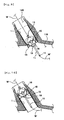
FIG. 7 is a view illustrating a vertical movement carrier descent operation; -
FIG. 8 is a view illustrating a horizontal movement carrier sliding operation; -
FIG. 9 is a view illustrating a sleeve removal tool insertion operation; -
FIG. 10 is a view illustrating a completely inserted sleeve removal tool; and -
FIG. 11 is a schematic view illustrating the removal of a thermal sleeve according to an embodiment of the present invention. - Hereinafter, an exemplary embodiment of the present invention will be described in detail with reference to the accompanying drawings.
- Referring to
FIGS. 1A to 5B illustrating a configuration of a thermal sleeve removal apparatus according to the exemplary embodiment of the present invention, the thermal sleeve removal apparatus includes asleeve removal tool 10 to forcibly remove athermal sleeve 1 installed in asafety injection pipe 120, ahorizontal movement carrier 20 to transport thesleeve removal tool 10 along acoolant pipe 110 via horizontal sliding movement thereof, and avertical movement carrier 30 to move thehorizontal movement carrier 20 up and down within areactor 100, and anextension pipe 40 connected to a check valve removal position of thesafety injection pipe 120 so as to guide a wire rope W and a cable for handling of thesleeve removal tool 10 and thehorizontal movement carrier 20. - More specifically, the
sleeve removal tool 10, as shown inFIGS. 2A to 2D , includes acorn head 12 and anintroduction eyebolt 13 provided at a front end of ashaft 11, a pullingeyebolt 14 provided at a rear end of theshaft 11, and aguide wheel 15 provided at an approximately middle position of theshaft 11 to guide insertion of thesleeve removal tool 10 into thesafety injection pipe 120. In addition, apressure plate 16 is provided below thecorn head 12 to maximize the effect of hydraulic pressure inside thesafety injection pipe 120. To this end, thepressure plate 16 has a foldable form and is divided into a plurality of sections. Aspring 17 is connected to an upper surface of thepressure plate 16 to apply an elastic force to thepressure plate 16. One end of atension release link 18 is connected to a lower surface of thepressure plate 16 to release a tensile force applied to thepressure plate 16, and the other end of thetension release link 18 is connected to aslider ring 19 that can slide along theshaft 11. - In particular, it is preferable that the
slider ring 19 be provided with awire connection loop 19a for connection of a wire rope used to forcibly release the tensile force applied to thepressure plate 16. - The
horizontal movement carrier 20, as shown inFIGS. 3A to 3C , consists of twobodies 21 connected to each other by use of alink 22. The twobodies 21 havecutout edges 21a facing each other to define a space therebetween so that thebodies 21 can be tilted toward or away from each other by a predetermined inclination angle. Aseating rod 23 is provided at a rear end of thehorizontal movement carrier 20 so that theshaft 11 of thesleeve removal tool 10 can be inserted into and seated in theseating rod 23. In addition, movingwheels 24 are mounted to the bottom and sidewalls of therespective bodies 21.Reference numeral 25 represents a wire connection loop provided for connection of wire ropes W and W'. Thewire connection loop 25 may be provided at the same position as theseating rod 23 for the insertion and seating of thesleeve removal tool 10. This may assure thesleeve removal tool 10 to be accurately positioned at an entrance of thesafety injection pipe 120 via sliding movement of thehorizontal movement carrier 20. - The
vertical movement carrier 30, as shown inFIGS. 4A to 4C , includes afirst anti-separation bar 31 provided at a rear end thereof to prevent separation of thehorizontal movement carrier 20, asecond anti-separation bar 32 pivotally coupled to a front end thereof by use of ahinge 32a, and a guidingfloor 33 protruding forward from the bottom thereof.Reference numeral 35 represents a wire connection loop for connection of a wire rope used to ascend or descend thevertical movement carrier 30. - The
extension pipe 40, as shown inFIGS. 5A and 5B , has a bentlower end portion 41 obliquely extending by a predetermined guidance angle to allow an initially inserted cable to move toward thecoolant pipe 110. - Hereinafter, a method for removing a thermal sleeve using the apparatus of the present invention having the above described configuration will be described with reference to
FIGS. 6 to 11 . - First, prior to performing the method of the present invention, a core support barrel (CSB) is reinstalled in a cavity of the
reactor 100 and then, the level of a fluid inside the cavity of thereactor 100 is lowered from 140 ft to 110 ft, causing thesafety injection pipe 120 to be exposed. Once thesafety injection pipe 120 is exposed, a check valve (not shown) provided at thesafety injection pipe 120 is disassembled to remove an element accommodated in thesafety injection pipe 120 and thereafter, theextension pipe 40 having a predetermined length is connected to thesafety injection pipe 120. - More specifically, typically, the cavity of the reactor, in which the core support barrel as a highly radioactive object is accommodated, is always filled with a boric acid solution to prevent the core support barrel from being exposed to the atmosphere. In general, the boric acid solution is charged to the level of 140 ft, the
thermal sleeve 1 is located at a height of approximately 105 ft, and the check valve (not shown) of thesafety injection pipe 120 is typically located at a height of 110 ft. - Accordingly, if it is attempted to directly install a wire rope to the check valve located at the height of 110 ft, this may cause leakage of the boric acid solution because the boric acid solution is charged to the level of 140 ft in the cavity of the reactor. For this reason, it is necessary to install the
extension pipe 40 along with aflange cover 42 after the level of the boric acid solution is lowered to 110 ft as described above. With this installation, it is possible to set a working location at a height of approximately 145 ft. - Next, if a worker A in a secondary working zone B that is set at the height of 145 ft via installation of the
extension pipe 40 as described above slowly inserts a cable into theextension pipe 40, the inserted cable is guided into thesafety injection pipe 120 and thecoolant pipe 110 by way of the bentlower end portion 41 of theextension pipe 40. - Once the cable is guided to the interior of the
reactor 100 via continuous insertion thereof, a worker in a primary working zone A provided at an upper end of thereactor 100 is able to grip and lift the cable by use of a nipper. - Thereafter, if the worker in the secondary working zone B pulls the cable after a required number of wire ropes W are connected to the lifted cable, the wire ropes W are pulled along with the cable, thereby being able to be moved toward the secondary working zone B by way of the interior of the
reactor 100, thecoolant pipe 110, thesafety injection pipe 120 and theextension pipe 40. - The
sleeve removal tool 10, thehorizontal movement carrier 20 and thevertical movement carrier 30, which constitute the removal apparatus of the present invention, are initially placed on the primary working zone A provided at the upper end of thereactor 100. In this case, one ends of the wire ropes W are connected respectively to one side of the respective devices (i.e. thesleeve removal tool 10, thehorizontal movement carrier 20, and the vertical movement carrier 30) for movement and installation of the devices, and additional pulling wire ropes W' are connected to the other side of the respective devices. In a state wherein thesleeve removal tool 10 is inserted in theseating rod 23 of thehorizontal movement carrier 20 and thehorizontal movement carrier 20 is seated in thevertical movement carrier 30 as shown inFIG. 1B , thevertical movement carrier 30 is guided to slowly descend inside thereactor 100. - If the
vertical movement carrier 30 continuously descends until it reaches an entrance of thecoolant pipe 110, the guidingfloor 33 of thevertical movement carrier 30 is caught by the entrance of thecoolant pipe 110. Thereby, as shown inFIG. 7 in the enlarged view of the portion "a" ofFIG. 6 , thevertical movement carrier 30 is located at the entrance of thecoolant pipe 110. - At this time, as the worker in the primary working zone A pulls up the wire rope W connected to the
second anti-separation bar 32 to allow thesecond anti-separation bar 32 to be pivotally rotated and raised about thehinge 32a, thehorizontal movement carrier 20 seated in thevertical movement carrier 30 is kept in a sliding movable state. - After the descent of the
vertical movement carrier 30 is completed at the fixed position, the worker in the secondary working zone B pulls the wire rope W connected to thehorizontal movement carrier 20, whereas the worker in the primary working zone A slowly releases the pulling wire rope W'. Thereby, as shown inFIG. 8 in the enlarged view of the portion "b" ofFIG. 6 , thehorizontal movement carrier 20 is moved along thecoolant pipe 110. - In particular, since the
horizontal movement carrier 20 consists of the twobodies 21 connected to each other by use of thelink 22, thehorizontal movement carrier 20 can smoothly pass through even a curved portion of thecoolant pipe 110. In this way, thehorizontal movement carrier 20 can slide and move to a junction between thesafety injection pipe 120 and thecoolant pipe 110. - In a state wherein the sliding movement of the
horizontal movement carrier 20 is completed, if the worker in the secondary working zone B pulls the wire rope W connected to thesleeve removal tool 10 that is seated in theseating rod 23, thesleeve removal tool 10, as shown inFIG. 9 , is guided upward into thethermal sleeve 1 that is an object to be removed from thesafety injection pipe 120. - In this case, since an inner diameter of the
thermal sleeve 1 decreases as thesleeve removal tool 10 is inserted into thethermal sleeve 1, it will be appreciated that thepressure plate 16 of thesleeve removal tool 10 may be temporarily kept in a downwardly folded state by overcoming the elasticity of thespring 17. - Then, if the
sleeve removal tool 10 completely passes through thethermal sleeve 1, as shown inFIG. 10 , thepressure plate 16 is unfolded to an original posture thereof by the elasticity of thespring 17, whereby the insertion of thesleeve removal tool 10 is completed. - After the worker in the secondary working zone B closes an open upper end of the
extension pipe 40 to prevent leakage of the solution in a state wherein the insertion of thesleeve removal tool 10 is completed, any one or both of a safety injection pump and a container water spray pump (not shown), which are previously installed at a front end of thesafety injection pipe 120, are simultaneously driven to generate high flow-rate hydraulic pressure inside thesafety injection pipe 120. The generated hydraulic pressure is applied to thecorn head 12 of thesleeve removal tool 10 and the upper surface of thepressure plate 16, generating a force pushing thethermal sleeve 1 downward and consequently, allowing thethermal sleeve 1 to be forcibly separated and removed from thesafety injection pipe 120. - In this case, it can be appreciated that the unfolded
pressure plate 16 serves as a dam, enabling transmission of the strong hydraulic pressure. - For reference, the safety injection pump and the container water spray pump are typically installed to supply cooling water in the event of an emergency situation of the reactor and therefore, a detailed functional description and an illustration thereof are omitted herein.
- The separated
thermal sleeve 1 drops and is seated on thehorizontal movement carrier 20 along with thesleeve removal tool 10 for collection of thethermal sleeve 1. - As the worker in the primary working zone A slowly pulls the pulling wire rope W' connected to the
horizontal movement carrier 20 and simultaneously, the worker in the secondary working zone B slowly releases the wire rope W, thehorizontal movement carrier 20 is guided to slide and move toward thereactor 100 along thecoolant pipe 110 and thereafter, is introduced into thevertical movement carrier 30. - Once the introduction of the
horizontal movement carrier 20 is confirmed, thesecond anti-separation bar 32 is again pivotally rotated and lowered to stably prevent separation of thehorizontal movement carrier 20 and thevertical movement carrier 30 is pulled to ascend inside thereactor 100, whereby the removal operation of the present invention is completed. - In the meantime, if the removal of the
thermal sleeve 1 ends in failure, it is necessary to remove and collect thesleeve removal tool 10 from thesafety injection pipe 120. However, since thepressure plate 16 is horizontally expanded and is caught at an upper end of thethermal sleeve 1, collection of thesleeve removal tool 10 may be difficult. - Therefore, in this case, it is necessary for the worker in the primary working zone A to pull the wire rope connected to the
wire connection loop 19a of theslider ring 19. Thereby, as theslider ring 19 is moved downward along theshaft 11, thepressure plate 16 is folded downward by thetension release link 18 connected between theslider ring 19 and thepressure plate 16. In this way, thepressure plate 16 can be released from thethermal sleeve 1. - Accordingly, if the wire rope W' connected to the pulling
eyebolt 14 is pulled at this state, thesleeve removal tool 10 can easily pass through and be discharged out of thesafety injection pipe 120 and thethermal sleeve 1 and thereafter, can drop into thehorizontal movement carrier 20, enabling easy collection of thesleeve removal tool 10. - With use of the above described apparatus of the present invention, the apparatus can be installed or removed only by wire rope handling of the workers in the primary working zone A and the secondary working zone B without a pipe cutting operation and the
thermal sleeve 1 can be removed by the hydraulic pressure applied to the safety injection pipe and the apparatus. Accordingly, the present invention can prevent problems, such as invasion of impurities, repetitious pipe welding, etc. - Further, since a remote operation and an underwater operation of the apparatus using the wire ropes are possible, it is possible to assure worker safety by minimizing radiation exposure.
- As apparent from the above description, with use of a thermal sleeve removal apparatus according to the present invention, if a thermal sleeve installed in a safety injection pipe is unintentionally separated, it is possible to remove the thermal sleeve without implementation of a pipe cutting operation. This has the effect of preventing invasion of impurities into pipes and preventing reliability deterioration due to repetitious welding of pipes.
- In particular, the thermal sleeve removal apparatus according to the present invention can allow workers in working zones distant from each other to perform a remote operation and an underwater operation by use of wire ropes. This has the effect of minimizing a negative effect on the workers due to radiation exposure.
- Although the preferred embodiment of the present invention has been disclosed for illustrative purposes, those skilled in the art will appreciate that various modifications are possible within the scope of the appended claims.
Claims (7)
- An apparatus for removing a thermal sleeve (1) from a cold leg of a reactor coolant system, the thermal sleeve being installed to minimize the effect of thermal shock at a junction between a coolant pipe (110) of a reactor and a safety injection pipe (120) connected to a midway position of the coolant pipe (110), the apparatus comprising:a sleeve removal tool (10) including a corn head (12) formed at a front end of a shaft (11) having a predetermined length, a pressure plate (16) provided below the corn head (12) to maximize the effect of hydraulic pressure inside the safety injection pipe (120), the pressure plate (16) being divided into a plurality of sections so as to be folded or unfolded, a spring (17) connected to an upper surface of the pressure plate (16) to keep the pressure plate (16) in an unfolded state, and a guide wheel (15) provided at a midway position of the shaft (11) to guide the sleeve removal tool (10) into the safety injection pipe (120):a horizontal movement carrier (20) including a plurality of bodies (21) connected to each other by use of a link (22), a seating rod (23) into which the sleeve removal tool (10) is seated and coupled, and moving wheels (24) installed to the respective bodies (21) so as to allow the horizontal movement carrier (20) to horizontally slide and move along the coolant pipe (110); anda vertical movement carrier (30) including first and second anti-separation bars (31, 32) provided respectively at front and rear ends thereof to prevent the horizontal movement carrier (20) from being separated from the vertical movement carrier (30) during upward or downward movement thereof inside the reactor, the second anti-separation bar (32) located at the front end of the vertical movement carrier being pivotally rotatable about a hinge (32a).
- The apparatus according to claim 1, further comprising an extension pipe (40) connected to the safety injection pipe (120) for connection of wire ropes (W) required for remote movement of the sleeve removal tool (10) and the horizontal movement carrier (20),
wherein the extension pipe (40) has a bent lower end portion obliquely extending toward the coolant pipe (110) by a predetermined guidance angle, and
wherein a flange cover (42) is provided at a coupling region of the extension pipe (40) and the safety injection pipe (120) to prevent fluid leakage under the effect of the hydraulic pressure inside the safety injection pipe (120). - The apparatus according to claim 1, wherein a slider ring (19) is movably installed to the shaft (11) of the sleeve removal tool (10), and a tension release link (18) is provided to connect the pressure plate (16) and the slider ring (19) to each other.
- The apparatus according to claim 1 or 3, wherein an introduction eyebolt (13) for connection of an introduction wire rope (W) is installed at the front end of the shaft (11) of the sleeve removal tool (10), and a pulling eyebolt (14) for connection of a pulling wire rope (W) is installed at a rear end of the shaft (11).
- The apparatus according to claim 4, wherein the slider ring (19) has a wire connection loop (19a) for connection of a wire rope (W) required to forcibly release a tensile force applied to the pressure plate (16).
- The apparatus according to claim 1, wherein the bodies (21) of the horizontal movement carrier (20) respectively have cutout edges facing each other.
- The apparatus according to claim 1 or 6, wherein the horizontal movement carrier (20) has a wire connection loop (25) for connection of the introduction and pulling wire ropes (W), and the wire connection loop (25) is formed at the same position as the seating rod (23).
Applications Claiming Priority (1)
| Application Number | Priority Date | Filing Date | Title |
|---|---|---|---|
| KR1020090123774A KR101067065B1 (en) | 2009-12-14 | 2009-12-14 | Heat transfer buffer sleeve removal device of reactor coolant system cold pipe |
Publications (3)
| Publication Number | Publication Date |
|---|---|
| EP2333783A2 EP2333783A2 (en) | 2011-06-15 |
| EP2333783A3 EP2333783A3 (en) | 2012-12-19 |
| EP2333783B1 true EP2333783B1 (en) | 2014-03-05 |
Family
ID=43608277
Family Applications (1)
| Application Number | Title | Priority Date | Filing Date |
|---|---|---|---|
| EP10156577.8A Active EP2333783B1 (en) | 2009-12-14 | 2010-03-16 | Apparatus for removing a thermal sleeve from a cold leg of a reactor cooling system |
Country Status (5)
| Country | Link |
|---|---|
| US (1) | US8243870B2 (en) |
| EP (1) | EP2333783B1 (en) |
| JP (1) | JP5143174B2 (en) |
| KR (1) | KR101067065B1 (en) |
| CN (1) | CN102097141B (en) |
Families Citing this family (6)
| Publication number | Priority date | Publication date | Assignee | Title |
|---|---|---|---|---|
| FR2914101B1 (en) * | 2007-03-22 | 2010-12-17 | Areva Np | NUCLEAR PRESSURIZER WITH WATER UNDER PRESSURE |
| KR101116500B1 (en) * | 2010-09-28 | 2012-02-28 | 윤여성 | Heat transfer buffer plate cutting device of nuclear power plant |
| KR101105838B1 (en) * | 2010-12-21 | 2012-01-13 | 한국수력원자력 주식회사 | Heat transfer buffer removal device and method |
| CN109780445B (en) * | 2018-12-20 | 2021-03-23 | 兰州空间技术物理研究所 | High-pressure air source device |
| CN114380184B (en) * | 2021-12-17 | 2024-10-29 | 哈尔滨电气动力装备有限公司 | Vertical process method for front adjustment of jacket heating jacket |
| KR102657127B1 (en) * | 2023-07-11 | 2024-04-15 | 한전케이피에스 주식회사 | Sleeve withdrawal device |
Family Cites Families (20)
| Publication number | Priority date | Publication date | Assignee | Title |
|---|---|---|---|---|
| US4006521A (en) * | 1975-06-02 | 1977-02-08 | Pedone John A | Pipe remover |
| FR2468978A1 (en) * | 1979-10-30 | 1981-05-08 | Commissariat Energie Atomique | NUCLEAR BOILER |
| DE3111814A1 (en) * | 1981-03-25 | 1982-10-07 | Kraftwerk Union AG, 4330 Mülheim | SELF-DRIVING TUBE MANIPULATOR FOR REMOTE CONTROLLED TRANSPORTATION OF TEST EQUIPMENT AND TOOLS LENGTH'S SPECIFIC FEED TRACKS, PREFERRED FOR NUCLEAR POWER PLANTS |
| JPS59107297A (en) * | 1982-12-10 | 1984-06-21 | 株式会社東芝 | Remotely exchanging device for feedwater sparger of reactor |
| FR2544454B1 (en) * | 1983-04-14 | 1985-07-05 | Commissariat Energie Atomique | DEVICE FOR REMOVABLE FASTENING OF AN INTERNAL STRUCTURE IN AN ENCLOSURE SUCH AS A CONDUIT OR A CONTAINER |
| FR2561030B1 (en) * | 1984-03-08 | 1986-10-31 | Framatome Sa | METHOD FOR REPLACING A SLEEVE MOUNTED WITHIN A CONDUIT AND DEVICES FOR CARRYING OUT SAID METHOD |
| US4682727A (en) * | 1986-03-04 | 1987-07-28 | Liberty Diversified Industries, Inc. | Utility tote container |
| FR2636767B1 (en) * | 1988-09-19 | 1990-12-14 | Framatome Sa | METHOD AND DEVICE FOR EXTRACTING A LOCKING SLEEVE FROM A REMOVABLE GUIDE TUBE FROM A FUEL ASSEMBLY OF A NUCLEAR REACTOR |
| US5227124A (en) * | 1989-08-04 | 1993-07-13 | Hitachi, Ltd. | Method and structure for preventive maintaining an elongated metal hollow member |
| US5377242A (en) * | 1993-11-15 | 1994-12-27 | B&W Nuclear Service Company | Method and system for emergency core cooling |
| KR0156508B1 (en) * | 1994-12-01 | 1998-12-15 | 이세엽 | Nozzle tube blocking device of nuclear power plant steam generator |
| DE69609927T2 (en) * | 1995-11-20 | 2001-04-05 | General Electric Co., Schenectady | Device for replacing control rod drives of a nuclear reactor |
| FR2742818B1 (en) * | 1995-12-22 | 1998-03-06 | Framatome Sa | METHOD FOR THE IMPERFECT FIXING OF TWO TUBULAR-SHAPED PARTS SCREWED ON TO ONE ANOTHER AND USE OF THE METHOD |
| US6345084B1 (en) * | 1999-11-19 | 2002-02-05 | General Electric Company | Apparatus and methods for replacing a core spray T-box/thermal sleeve in a nuclear reactor |
| US6450104B1 (en) * | 2000-04-28 | 2002-09-17 | North Carolina State University | Modular observation crawler and sensing instrument and method for operating same |
| FR2837612B1 (en) * | 2002-03-22 | 2004-07-16 | Framatome Anp | METHOD AND DEVICE FOR REPLACING AND METHOD FOR REPAIRING A SECTION OF A PIPE OF THE PRIMARY CIRCUIT OF A NUCLEAR REACTOR |
| KR100667363B1 (en) | 2004-05-06 | 2007-01-10 | (주)유진티엠씨 | Removal method of heat transfer buffer plate of nuclear power plant |
| US7203263B2 (en) * | 2004-07-26 | 2007-04-10 | General Electric Company | Core spray apparatus and method for installing the same |
| KR100598352B1 (en) * | 2004-11-16 | 2006-07-06 | 두산중공업 주식회사 | How to remove the buffer pipe installed in the safety injection nozzle of the reactor low temperature pipe |
| KR101067232B1 (en) * | 2009-12-14 | 2011-09-22 | 한전케이피에스 주식회사 | How to remove the heat transfer buffer sleeve of the reactor coolant system cold tube |
-
2009
- 2009-12-14 KR KR1020090123774A patent/KR101067065B1/en active Active
-
2010
- 2010-03-16 EP EP10156577.8A patent/EP2333783B1/en active Active
- 2010-03-30 JP JP2010077137A patent/JP5143174B2/en active Active
- 2010-04-14 US US12/760,060 patent/US8243870B2/en active Active
- 2010-05-21 CN CN201010184745XA patent/CN102097141B/en active Active
Also Published As
| Publication number | Publication date |
|---|---|
| CN102097141A (en) | 2011-06-15 |
| EP2333783A2 (en) | 2011-06-15 |
| KR101067065B1 (en) | 2011-09-22 |
| US8243870B2 (en) | 2012-08-14 |
| US20110142188A1 (en) | 2011-06-16 |
| JP2011123044A (en) | 2011-06-23 |
| CN102097141B (en) | 2013-06-19 |
| EP2333783A3 (en) | 2012-12-19 |
| JP5143174B2 (en) | 2013-02-13 |
| KR20110067259A (en) | 2011-06-22 |
Similar Documents
| Publication | Publication Date | Title |
|---|---|---|
| US8243870B2 (en) | Apparatus for removing thermal sleeve from cold leg of reactor coolant system | |
| EP2333784B1 (en) | Method for removing a thermal sleeve from a cold leg of a reactor cooling system | |
| KR102252210B1 (en) | Device for launching a subsurface mining vehicle into a water mass and recovering the same from the water mass | |
| EP2430283B1 (en) | Subsea overload release system and method | |
| JPH0216290A (en) | Method and device for recovering travelling tool/guide frame device | |
| US11289886B2 (en) | Quick release connection flange | |
| EP2962975A1 (en) | An installation apparatus | |
| CN106507748B (en) | A kind of untethered submersible water surface lays retracting device | |
| EP2665958B1 (en) | Subsea pipeline connecting apparatus and method | |
| GB2382635A (en) | Connecting a conduit to a sub-sea structure | |
| US20130168103A1 (en) | Damping sleeve and anchoring method | |
| GB2271826A (en) | Apparatus for bending plastic pipe | |
| CN219771719U (en) | High-safety retraction device for channel robot | |
| US8215889B2 (en) | System and method for high current recovery cursor | |
| CN112943131B (en) | Marine riser dismantling method | |
| JP2015028495A (en) | Method for carrying out nuclear fuel material in a nuclear power plant | |
| JP2009280389A (en) | Curing method in asbestos treatment | |
| JP6941571B2 (en) | Survey system and survey method | |
| CN116395617B (en) | A high-safety deployment and retrieval device for trench robots | |
| KR101952950B1 (en) | Dismantle method of bulkhead in underwater water intake tunnel | |
| ZA200906977B (en) | Method for recovering at least one fuel assembly which has remained engaged below an upper plate of a core of a pressurized water nuclear reactor | |
| JP3646267B1 (en) | Sewage pipe repair material insertion device | |
| JP2016045153A (en) | Positioner | |
| CN203638937U (en) | Cage safety door | |
| JPH03252596A (en) | Replacing device for fuel assembly |
Legal Events
| Date | Code | Title | Description |
|---|---|---|---|
| PUAI | Public reference made under article 153(3) epc to a published international application that has entered the european phase |
Free format text: ORIGINAL CODE: 0009012 |
|
| AK | Designated contracting states |
Kind code of ref document: A2 Designated state(s): AT BE BG CH CY CZ DE DK EE ES FI FR GB GR HR HU IE IS IT LI LT LU LV MC MK MT NL NO PL PT RO SE SI SK SM TR |
|
| PUAL | Search report despatched |
Free format text: ORIGINAL CODE: 0009013 |
|
| AK | Designated contracting states |
Kind code of ref document: A3 Designated state(s): AT BE BG CH CY CZ DE DK EE ES FI FR GB GR HR HU IE IS IT LI LT LU LV MC MK MT NL NO PL PT RO SE SI SK SM TR |
|
| RIC1 | Information provided on ipc code assigned before grant |
Ipc: G21C 17/017 20060101ALI20121113BHEP Ipc: G21C 13/032 20060101AFI20121113BHEP Ipc: G21C 19/20 20060101ALI20121113BHEP Ipc: F16L 55/00 20060101ALI20121113BHEP Ipc: G21C 19/16 20060101ALI20121113BHEP |
|
| 17P | Request for examination filed |
Effective date: 20130529 |
|
| RBV | Designated contracting states (corrected) |
Designated state(s): AT BE BG CH CY CZ DE DK EE ES FI FR GB GR HR HU IE IS IT LI LT LU LV MC MK MT NL NO PL PT RO SE SI SK SM TR |
|
| GRAP | Despatch of communication of intention to grant a patent |
Free format text: ORIGINAL CODE: EPIDOSNIGR1 |
|
| RIC1 | Information provided on ipc code assigned before grant |
Ipc: G21C 17/017 20060101ALI20130805BHEP Ipc: G21C 13/032 20060101AFI20130805BHEP Ipc: G21C 19/20 20060101ALI20130805BHEP Ipc: F16L 55/00 20060101ALI20130805BHEP Ipc: B08B 9/04 20060101ALI20130805BHEP Ipc: G21C 19/16 20060101ALI20130805BHEP |
|
| RIC1 | Information provided on ipc code assigned before grant |
Ipc: G21C 13/032 20060101AFI20130827BHEP Ipc: G21C 19/20 20060101ALI20130827BHEP Ipc: F16L 55/00 20060101ALI20130827BHEP Ipc: G21C 17/017 20060101ALI20130827BHEP Ipc: B08B 9/04 20060101ALI20130827BHEP Ipc: F16L 55/18 20060101ALI20130827BHEP Ipc: G21C 19/16 20060101ALI20130827BHEP |
|
| INTG | Intention to grant announced |
Effective date: 20130910 |
|
| GRAS | Grant fee paid |
Free format text: ORIGINAL CODE: EPIDOSNIGR3 |
|
| GRAA | (expected) grant |
Free format text: ORIGINAL CODE: 0009210 |
|
| AK | Designated contracting states |
Kind code of ref document: B1 Designated state(s): AT BE BG CH CY CZ DE DK EE ES FI FR GB GR HR HU IE IS IT LI LT LU LV MC MK MT NL NO PL PT RO SE SI SK SM TR |
|
| REG | Reference to a national code |
Ref country code: GB Ref legal event code: FG4D |
|
| REG | Reference to a national code |
Ref country code: CH Ref legal event code: EP |
|
| REG | Reference to a national code |
Ref country code: AT Ref legal event code: REF Ref document number: 655359 Country of ref document: AT Kind code of ref document: T Effective date: 20140315 |
|
| REG | Reference to a national code |
Ref country code: IE Ref legal event code: FG4D |
|
| REG | Reference to a national code |
Ref country code: DE Ref legal event code: R096 Ref document number: 602010013892 Country of ref document: DE Effective date: 20140417 |
|
| REG | Reference to a national code |
Ref country code: AT Ref legal event code: MK05 Ref document number: 655359 Country of ref document: AT Kind code of ref document: T Effective date: 20140305 |
|
| REG | Reference to a national code |
Ref country code: NL Ref legal event code: VDEP Effective date: 20140305 |
|
| PG25 | Lapsed in a contracting state [announced via postgrant information from national office to epo] |
Ref country code: LT Free format text: LAPSE BECAUSE OF FAILURE TO SUBMIT A TRANSLATION OF THE DESCRIPTION OR TO PAY THE FEE WITHIN THE PRESCRIBED TIME-LIMIT Effective date: 20140305 Ref country code: NO Free format text: LAPSE BECAUSE OF FAILURE TO SUBMIT A TRANSLATION OF THE DESCRIPTION OR TO PAY THE FEE WITHIN THE PRESCRIBED TIME-LIMIT Effective date: 20140605 |
|
| REG | Reference to a national code |
Ref country code: LT Ref legal event code: MG4D |
|
| PG25 | Lapsed in a contracting state [announced via postgrant information from national office to epo] |
Ref country code: FI Free format text: LAPSE BECAUSE OF FAILURE TO SUBMIT A TRANSLATION OF THE DESCRIPTION OR TO PAY THE FEE WITHIN THE PRESCRIBED TIME-LIMIT Effective date: 20140305 Ref country code: CY Free format text: LAPSE BECAUSE OF FAILURE TO SUBMIT A TRANSLATION OF THE DESCRIPTION OR TO PAY THE FEE WITHIN THE PRESCRIBED TIME-LIMIT Effective date: 20140305 Ref country code: SE Free format text: LAPSE BECAUSE OF FAILURE TO SUBMIT A TRANSLATION OF THE DESCRIPTION OR TO PAY THE FEE WITHIN THE PRESCRIBED TIME-LIMIT Effective date: 20140305 Ref country code: AT Free format text: LAPSE BECAUSE OF FAILURE TO SUBMIT A TRANSLATION OF THE DESCRIPTION OR TO PAY THE FEE WITHIN THE PRESCRIBED TIME-LIMIT Effective date: 20140305 |
|
| PG25 | Lapsed in a contracting state [announced via postgrant information from national office to epo] |
Ref country code: HR Free format text: LAPSE BECAUSE OF FAILURE TO SUBMIT A TRANSLATION OF THE DESCRIPTION OR TO PAY THE FEE WITHIN THE PRESCRIBED TIME-LIMIT Effective date: 20140305 Ref country code: LV Free format text: LAPSE BECAUSE OF FAILURE TO SUBMIT A TRANSLATION OF THE DESCRIPTION OR TO PAY THE FEE WITHIN THE PRESCRIBED TIME-LIMIT Effective date: 20140305 |
|
| PG25 | Lapsed in a contracting state [announced via postgrant information from national office to epo] |
Ref country code: NL Free format text: LAPSE BECAUSE OF FAILURE TO SUBMIT A TRANSLATION OF THE DESCRIPTION OR TO PAY THE FEE WITHIN THE PRESCRIBED TIME-LIMIT Effective date: 20140305 Ref country code: CZ Free format text: LAPSE BECAUSE OF FAILURE TO SUBMIT A TRANSLATION OF THE DESCRIPTION OR TO PAY THE FEE WITHIN THE PRESCRIBED TIME-LIMIT Effective date: 20140305 Ref country code: EE Free format text: LAPSE BECAUSE OF FAILURE TO SUBMIT A TRANSLATION OF THE DESCRIPTION OR TO PAY THE FEE WITHIN THE PRESCRIBED TIME-LIMIT Effective date: 20140305 Ref country code: BG Free format text: LAPSE BECAUSE OF FAILURE TO SUBMIT A TRANSLATION OF THE DESCRIPTION OR TO PAY THE FEE WITHIN THE PRESCRIBED TIME-LIMIT Effective date: 20140605 Ref country code: BE Free format text: LAPSE BECAUSE OF FAILURE TO SUBMIT A TRANSLATION OF THE DESCRIPTION OR TO PAY THE FEE WITHIN THE PRESCRIBED TIME-LIMIT Effective date: 20140305 Ref country code: RO Free format text: LAPSE BECAUSE OF FAILURE TO SUBMIT A TRANSLATION OF THE DESCRIPTION OR TO PAY THE FEE WITHIN THE PRESCRIBED TIME-LIMIT Effective date: 20140305 Ref country code: IS Free format text: LAPSE BECAUSE OF FAILURE TO SUBMIT A TRANSLATION OF THE DESCRIPTION OR TO PAY THE FEE WITHIN THE PRESCRIBED TIME-LIMIT Effective date: 20140705 |
|
| REG | Reference to a national code |
Ref country code: CH Ref legal event code: PL |
|
| PG25 | Lapsed in a contracting state [announced via postgrant information from national office to epo] |
Ref country code: PL Free format text: LAPSE BECAUSE OF FAILURE TO SUBMIT A TRANSLATION OF THE DESCRIPTION OR TO PAY THE FEE WITHIN THE PRESCRIBED TIME-LIMIT Effective date: 20140305 Ref country code: SK Free format text: LAPSE BECAUSE OF FAILURE TO SUBMIT A TRANSLATION OF THE DESCRIPTION OR TO PAY THE FEE WITHIN THE PRESCRIBED TIME-LIMIT Effective date: 20140305 Ref country code: ES Free format text: LAPSE BECAUSE OF FAILURE TO SUBMIT A TRANSLATION OF THE DESCRIPTION OR TO PAY THE FEE WITHIN THE PRESCRIBED TIME-LIMIT Effective date: 20140305 |
|
| REG | Reference to a national code |
Ref country code: DE Ref legal event code: R097 Ref document number: 602010013892 Country of ref document: DE |
|
| PG25 | Lapsed in a contracting state [announced via postgrant information from national office to epo] |
Ref country code: PT Free format text: LAPSE BECAUSE OF FAILURE TO SUBMIT A TRANSLATION OF THE DESCRIPTION OR TO PAY THE FEE WITHIN THE PRESCRIBED TIME-LIMIT Effective date: 20140707 |
|
| REG | Reference to a national code |
Ref country code: IE Ref legal event code: MM4A |
|
| PLBE | No opposition filed within time limit |
Free format text: ORIGINAL CODE: 0009261 |
|
| STAA | Information on the status of an ep patent application or granted ep patent |
Free format text: STATUS: NO OPPOSITION FILED WITHIN TIME LIMIT |
|
| PG25 | Lapsed in a contracting state [announced via postgrant information from national office to epo] |
Ref country code: LI Free format text: LAPSE BECAUSE OF NON-PAYMENT OF DUE FEES Effective date: 20140331 Ref country code: DK Free format text: LAPSE BECAUSE OF FAILURE TO SUBMIT A TRANSLATION OF THE DESCRIPTION OR TO PAY THE FEE WITHIN THE PRESCRIBED TIME-LIMIT Effective date: 20140305 Ref country code: CH Free format text: LAPSE BECAUSE OF NON-PAYMENT OF DUE FEES Effective date: 20140331 Ref country code: MC Free format text: LAPSE BECAUSE OF FAILURE TO SUBMIT A TRANSLATION OF THE DESCRIPTION OR TO PAY THE FEE WITHIN THE PRESCRIBED TIME-LIMIT Effective date: 20140305 Ref country code: IE Free format text: LAPSE BECAUSE OF NON-PAYMENT OF DUE FEES Effective date: 20140316 |
|
| 26N | No opposition filed |
Effective date: 20141208 |
|
| GBPC | Gb: european patent ceased through non-payment of renewal fee |
Effective date: 20140605 |
|
| REG | Reference to a national code |
Ref country code: DE Ref legal event code: R097 Ref document number: 602010013892 Country of ref document: DE Effective date: 20141208 |
|
| PG25 | Lapsed in a contracting state [announced via postgrant information from national office to epo] |
Ref country code: IT Free format text: LAPSE BECAUSE OF FAILURE TO SUBMIT A TRANSLATION OF THE DESCRIPTION OR TO PAY THE FEE WITHIN THE PRESCRIBED TIME-LIMIT Effective date: 20140305 |
|
| PG25 | Lapsed in a contracting state [announced via postgrant information from national office to epo] |
Ref country code: SI Free format text: LAPSE BECAUSE OF FAILURE TO SUBMIT A TRANSLATION OF THE DESCRIPTION OR TO PAY THE FEE WITHIN THE PRESCRIBED TIME-LIMIT Effective date: 20140305 Ref country code: GB Free format text: LAPSE BECAUSE OF NON-PAYMENT OF DUE FEES Effective date: 20140605 |
|
| REG | Reference to a national code |
Ref country code: FR Ref legal event code: PLFP Year of fee payment: 7 |
|
| PG25 | Lapsed in a contracting state [announced via postgrant information from national office to epo] |
Ref country code: MT Free format text: LAPSE BECAUSE OF FAILURE TO SUBMIT A TRANSLATION OF THE DESCRIPTION OR TO PAY THE FEE WITHIN THE PRESCRIBED TIME-LIMIT Effective date: 20140305 |
|
| PG25 | Lapsed in a contracting state [announced via postgrant information from national office to epo] |
Ref country code: SM Free format text: LAPSE BECAUSE OF FAILURE TO SUBMIT A TRANSLATION OF THE DESCRIPTION OR TO PAY THE FEE WITHIN THE PRESCRIBED TIME-LIMIT Effective date: 20140305 |
|
| PG25 | Lapsed in a contracting state [announced via postgrant information from national office to epo] |
Ref country code: GR Free format text: LAPSE BECAUSE OF FAILURE TO SUBMIT A TRANSLATION OF THE DESCRIPTION OR TO PAY THE FEE WITHIN THE PRESCRIBED TIME-LIMIT Effective date: 20140606 |
|
| PG25 | Lapsed in a contracting state [announced via postgrant information from national office to epo] |
Ref country code: HU Free format text: LAPSE BECAUSE OF FAILURE TO SUBMIT A TRANSLATION OF THE DESCRIPTION OR TO PAY THE FEE WITHIN THE PRESCRIBED TIME-LIMIT; INVALID AB INITIO Effective date: 20100316 Ref country code: LU Free format text: LAPSE BECAUSE OF NON-PAYMENT OF DUE FEES Effective date: 20140316 Ref country code: TR Free format text: LAPSE BECAUSE OF FAILURE TO SUBMIT A TRANSLATION OF THE DESCRIPTION OR TO PAY THE FEE WITHIN THE PRESCRIBED TIME-LIMIT Effective date: 20140305 |
|
| REG | Reference to a national code |
Ref country code: FR Ref legal event code: PLFP Year of fee payment: 8 |
|
| REG | Reference to a national code |
Ref country code: FR Ref legal event code: PLFP Year of fee payment: 9 |
|
| PG25 | Lapsed in a contracting state [announced via postgrant information from national office to epo] |
Ref country code: MK Free format text: LAPSE BECAUSE OF FAILURE TO SUBMIT A TRANSLATION OF THE DESCRIPTION OR TO PAY THE FEE WITHIN THE PRESCRIBED TIME-LIMIT Effective date: 20140305 |
|
| PGFP | Annual fee paid to national office [announced via postgrant information from national office to epo] |
Ref country code: DE Payment date: 20241223 Year of fee payment: 16 |
|
| PGFP | Annual fee paid to national office [announced via postgrant information from national office to epo] |
Ref country code: FR Payment date: 20251223 Year of fee payment: 17 |