EP2333641A2 - Optisches Hochpräzisionsnavigationsgerät - Google Patents
Optisches Hochpräzisionsnavigationsgerät Download PDFInfo
- Publication number
- EP2333641A2 EP2333641A2 EP10194665A EP10194665A EP2333641A2 EP 2333641 A2 EP2333641 A2 EP 2333641A2 EP 10194665 A EP10194665 A EP 10194665A EP 10194665 A EP10194665 A EP 10194665A EP 2333641 A2 EP2333641 A2 EP 2333641A2
- Authority
- EP
- European Patent Office
- Prior art keywords
- sensor
- control
- movement
- controller
- radiation
- Prior art date
- Legal status (The legal status is an assumption and is not a legal conclusion. Google has not performed a legal analysis and makes no representation as to the accuracy of the status listed.)
- Withdrawn
Links
Images


Classifications
-
- G—PHYSICS
- G06—COMPUTING OR CALCULATING; COUNTING
- G06F—ELECTRIC DIGITAL DATA PROCESSING
- G06F3/00—Input arrangements for transferring data to be processed into a form capable of being handled by the computer; Output arrangements for transferring data from processing unit to output unit, e.g. interface arrangements
- G06F3/01—Input arrangements or combined input and output arrangements for interaction between user and computer
- G06F3/03—Arrangements for converting the position or the displacement of a member into a coded form
- G06F3/0304—Detection arrangements using opto-electronic means
- G06F3/0317—Detection arrangements using opto-electronic means in co-operation with a patterned surface, e.g. absolute position or relative movement detection for an optical mouse or pen positioned with respect to a coded surface
-
- G—PHYSICS
- G06—COMPUTING OR CALCULATING; COUNTING
- G06F—ELECTRIC DIGITAL DATA PROCESSING
- G06F3/00—Input arrangements for transferring data to be processed into a form capable of being handled by the computer; Output arrangements for transferring data from processing unit to output unit, e.g. interface arrangements
- G06F3/01—Input arrangements or combined input and output arrangements for interaction between user and computer
- G06F3/03—Arrangements for converting the position or the displacement of a member into a coded form
- G06F3/033—Pointing devices displaced or positioned by the user, e.g. mice, trackballs, pens or joysticks; Accessories therefor
- G06F3/0354—Pointing devices displaced or positioned by the user, e.g. mice, trackballs, pens or joysticks; Accessories therefor with detection of two-dimensional [2D] relative movements between the device, or an operating part thereof, and a plane or surface, e.g. 2D mice, trackballs, pens or pucks
- G06F3/03543—Mice or pucks
-
- G—PHYSICS
- G06—COMPUTING OR CALCULATING; COUNTING
- G06F—ELECTRIC DIGITAL DATA PROCESSING
- G06F3/00—Input arrangements for transferring data to be processed into a form capable of being handled by the computer; Output arrangements for transferring data from processing unit to output unit, e.g. interface arrangements
- G06F3/01—Input arrangements or combined input and output arrangements for interaction between user and computer
- G06F3/03—Arrangements for converting the position or the displacement of a member into a coded form
- G06F3/033—Pointing devices displaced or positioned by the user, e.g. mice, trackballs, pens or joysticks; Accessories therefor
- G06F3/0354—Pointing devices displaced or positioned by the user, e.g. mice, trackballs, pens or joysticks; Accessories therefor with detection of two-dimensional [2D] relative movements between the device, or an operating part thereof, and a plane or surface, e.g. 2D mice, trackballs, pens or pucks
- G06F3/03547—Touch pads, in which fingers can move on a surface
Definitions
- This invention is in the field of hand held optical navigation device, and in particular to those hand held optical device commonly known as mice used for computer navigation and control.
- Mice are a very common user input device for a graphical environment. These devices are hand held with the user moving the mouse with their hand, and more specifically, by twisting their wrist or moving their elbow. While this produces large amounts of movement, the human body does not have very accurate control over the relevant muscles. Furthermore, the navigation / correlation technique used in optical mice are inefficient at low speeds as there is little movement between successive images.
- the functionality of the scroll wheel was improved by Microsoft (RTM) by adding a "tilt” function to the scroll wheel. This has control in the orthogonal axis to the scroll, but by only a limited amount (-X, 0 or +X).
- the Apple (RTM) "mighty mouse” replaces the scroll wheel with a trackball on the top of the mouse. This is used to provide functionality similar to the tilt wheel, i.e. horizontal scrolling. Probably due to its small size, it is not good enough to be used as a main cursor control device.
- a handheld optical navigation device comprising:
- Said device may comprise a second radiation source for producing a beam of radiation onto said object so as to obtain said second image.
- Said device may comprise a mousing surface, said second sensor imaging movement of said object on said mousing surface.
- Said device may be designed such that said mousing surface is easily manipulated by a finger or thumb.
- Said device may further comprise an optical element including at least one frustrated total internal reflection (F-TIR) surface capable of causing frustrated total internal reflection of the beam of radiation when said object contacts said mousing surface of said optical element, to thereby generate said second image.
- the optical element may comprise at least one further surface for directing radiation from the radiation source to at least one F-TIR surface.
- the optical element may comprise at least one additional surface for directing radiation from the F-TIR surface to the second sensor.
- Said optical element may be formed from a single piece construction.
- Said first sensor and said second sensor may both share a single substrate.
- Said device may comprise a controller for controlling said first and second sensors and said radiation source.
- the device may comprise separate control lines, motion lines and shutdown lines connecting the controller independently to each of said first and second sensor, said motion line for signalling if a sensor has detected movement and said shutdown line for enabling the controller to power down a sensor.
- said controller and said first and second sensors may be connected in series such that said controller has direct control, motion and shutdown lines to only one of said sensors.
- said device may comprise an additional control line such that the control pins of said first and second sensors are connected in parallel to a single controller pin.
- Said device may be operable such that for high speed operation, data from said first sensor is used, and for high precision operation, data from said second sensor is used.
- Said device may be operable such that should a parameter related to the speed of movement of said device across said surface indicate speed above a threshold, data from said first sensor is used for said control function and should said parameter related to the speed of movement of said device across said surface indicate speed below said threshold data, data from said second sensor is used for said control function.
- Said device may be operable such that said second sensor is deactivated when not being used for deriving the control function.
- Said device may be operable such that said second sensor is less sensitive to movement than said first sensor.
- the output resolution of said first sensor may be larger than the output resolution of said second sensor.
- Figure 1 shows the cross section of a typical optical mouse. Shown is a light source (LED or VCSEL) 100 from which light is directed / focussed onto an object (table, desk, paper, mouse mat) 110 and the resulting image observed on an optical sensor 120 which tracks movement. Typically there are low-friction pads 130 mounted on the optical mouse to reduce friction and allow the mouse to move smoothly over the surface. Typically there are one or more buttons on the top of the mouse (not shown), and usually a scroll wheel or tilt wheel 140.
- LED or VCSEL light source
- object table, desk, paper, mouse mat
- an optical sensor 120 which tracks movement.
- low-friction pads 130 mounted on the optical mouse to reduce friction and allow the mouse to move smoothly over the surface.
- buttons on the top of the mouse (not shown), and usually a scroll wheel or tilt wheel 140.
- Figure 2 shows a cross section of a mouse device according to one embodiment of the invention.
- the difference between this and the mouse of Figure 1 is the addition of a second optical sensor unit 250 and associated light source 260.
- the "Mousing surface" 270 provided by this second sensor arrangement 250, 260 is positioned directly underneath the position of the index finger when it is in a relaxed or comfortable state. Consequently the sensor unit 250 will receive an image based on light reflected off an object, such as a finger, on the mousing surface 270.
- the first optical sensor 220 and light source 200 are located on a first, main substrate (printed circuit board, PCB) 280.
- the second optical sensor (and associated light source) is mounted on a second substrate (PCB) 290.
- the mousing surface could be on a side of the device (with a plane approximately perpendicular to that depicted) for manipulation by a thumb.
- Figure 3 shows an improved mouse from that of Figure 2 .
- the second optical sensor 250 and associated light source 260 has been mounted on the same substrate 280 as the first optical sensor 220. This reduced the thickness, provides greater comfort to the user and also decreases the manufacturing cost.
- Figure 4 illustrates one of a number of implementing architectures according to an embodiment of the invention. It shows the first motion sensor (looking down) 220, the second motion sensor (looking up) 250 and the controller 400, which may be a 12C or SPI or similar control interface.
- the connections of the "control”, “Motion” (used to signal if the sensor has detected movement) and (optionally) “Shutdown” (used by a host to power down a sensor to save energy) pins are shown for the sensors 220, 250 and controller 400.
- “Motion” and “shutdown” are independently connected to the controller device 400.
- the output from the controller 400 is preferably a USB (universal serial bus) output or may even be a signal suitable for RF (radio frequency) modulation, in the case of a wireless mouse.
- USB universal serial bus
- RF radio frequency
- Figure 5 shows an optimized system where the controller device 400 is connected to only one sensor 250. Due to size constraints the down-facing sensor ⁇ desk ⁇ 250 has more space available than the up-facing ⁇ finger ⁇ sensor 220. Therefore, the down-facing sensor 250 would typically receive the inputs from the up-facing sensor 220 and modify / relay these to the controller 400. In the arrangement of Figure 4 the decision to use either the down-facing sensor or up-facing sensor is made by the controller device 400. In the arrangements of Figures 5 & 6 , the up facing sensor 220 would be programmed (typically via the control interface) with the speed threshold and the switching between the sensors being made by up facing sensor 220.
- Figure 6 shows a more efficient system architecture which may be possible, depending on the control bus uses. For example, if an 12C bus is used, there is no need to have a control input on the down-facing sensor 220, thus dispensing with the need of two extra pads / connections on the device. Furthermore the 12C bus supports multiple (slave) devices, which means that the two sensors 220, 250 can be connected in parallel.
- the device operates by using the two control signals from the two optical sensors in a co-operative manner so as to output a single navigation output.
- the mouse For large movements and high speed operation, the mouse itself is moved across the surface below it, and motion data from the down-facing sensor 220 is used.
- the mouse For high precision movements, the mouse is kept largely stationary and the finger (typically index) is moved over the mousing surface 270 of the device.
- the finger typically index
- this operation results in a device which provides increased accuracy control.
- data from the down facing sensor 220 should be ignored for the purposes of control when the mouse is largely stationary, or its speed is below a threshold level.
- the output from the two sensors provides for a single navigational output. This is as opposed to an output that comprises two separate positional signals as is the case with a mouse and scroll wheel, where the mouse controls a cursor and the scroll wheel controls the scrolling in a window.
- control would, for example, control the same cursor, providing a coarse control and fine control of the cursor.
- control is not limited to that via a cursor, and the control method could be any other suitable method, including scroll, zoom etc.
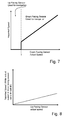
- Figure 7 shows a plot of the speed of the mouse as detected by the down-facing sensor 220 against its actual speed for a mouse configured in this way.
- T e.g. 2-5mm/sec
- the navigation data from the down-facing sensor 220 is used, and the reported speed increases linearly with increase in actual speed (Of course, this relationship does not need to continue in a linear fashion but instead may "accelerate” as is known in the art).
- T e.g. 2-5mm/sec
- the data from the down-facing sensor 220 is disregarded and the reported speed drops to zero (first period on graph). During this period data from the up-facing sensor 250 is used instead. This technique avoids small nudges in the mouse when a user is sliding a finger on the top surface from being used as valid cursor movement data.
- the output resolution (counts per inch) from the two sensors can be made different, such that the down-facing sensor outputs 800 cpi (i.e. one inch of travel outputs 800 counts) while the up facing sensor outputs 200 cpi. Therefore, in the latter case, the finger has to move further to output the same number of counts. This decrease of sensitivity increases the positional accuracy of the system.
- the different output counts may be achieved either by changing the motion gain on the sensor or by varying the magnification in the optics (x0. 5 Vs x0.2 5 ) or by using sensors with different array sizes (20 * 20 pixels Vs 40 * 40 pixels).
- Figure 8 shows a graph similar (axes are scaled the same) to that of Figure 7 for the up facing sensor 250 during the first period of graph 7. It can be seen that the reported speed increases linearly with actual speed of the finger on the sensor, but with a different slope than that of Figure 7 , representing the difference in output resolution. Of course, the reported speed on this graph drops to zero should the mouse speed recorded by the down facing sensor 220 pass the threshold value T.
Landscapes
- Engineering & Computer Science (AREA)
- General Engineering & Computer Science (AREA)
- Theoretical Computer Science (AREA)
- Human Computer Interaction (AREA)
- Physics & Mathematics (AREA)
- General Physics & Mathematics (AREA)
- Position Input By Displaying (AREA)
- Switches Operated By Changes In Physical Conditions (AREA)
Applications Claiming Priority (1)
| Application Number | Priority Date | Filing Date | Title |
|---|---|---|---|
| GBGB0921798.5A GB0921798D0 (en) | 2009-12-14 | 2009-12-14 | High precision optical navigation device |
Publications (2)
| Publication Number | Publication Date |
|---|---|
| EP2333641A2 true EP2333641A2 (de) | 2011-06-15 |
| EP2333641A3 EP2333641A3 (de) | 2014-07-23 |
Family
ID=41667038
Family Applications (1)
| Application Number | Title | Priority Date | Filing Date |
|---|---|---|---|
| EP10194665.5A Withdrawn EP2333641A3 (de) | 2009-12-14 | 2010-12-13 | Optisches Hochpräzisionsnavigationsgerät |
Country Status (3)
| Country | Link |
|---|---|
| US (1) | US20110141021A1 (de) |
| EP (1) | EP2333641A3 (de) |
| GB (1) | GB0921798D0 (de) |
Families Citing this family (1)
| Publication number | Priority date | Publication date | Assignee | Title |
|---|---|---|---|---|
| US11625108B2 (en) * | 2020-09-30 | 2023-04-11 | Logitech Europe S.A. | Working range and lift detection in an input device |
Family Cites Families (12)
| Publication number | Priority date | Publication date | Assignee | Title |
|---|---|---|---|---|
| US5191641A (en) * | 1988-09-26 | 1993-03-02 | Sharp Kabushiki Kaisha | Cursor shift speed control system |
| US5661502A (en) * | 1996-02-16 | 1997-08-26 | Ast Research, Inc. | Self-adjusting digital filter for smoothing computer mouse movement |
| US6489948B1 (en) * | 2000-04-20 | 2002-12-03 | Benny Chi Wah Lau | Computer mouse having multiple cursor positioning inputs and method of operation |
| US20040017355A1 (en) * | 2002-07-24 | 2004-01-29 | Youngtack Shim | Cursor control systems and methods |
| US7358963B2 (en) * | 2002-09-09 | 2008-04-15 | Apple Inc. | Mouse having an optically-based scrolling feature |
| US7576726B2 (en) * | 2005-05-25 | 2009-08-18 | Avago Technologies Ecbu Ip (Singapore) Pte. Ltd. | Dual-positioning controller and method for controlling an indicium on a display of an electronic device |
| US8077147B2 (en) * | 2005-12-30 | 2011-12-13 | Apple Inc. | Mouse with optical sensing surface |
| US7760184B2 (en) * | 2006-04-03 | 2010-07-20 | Nokia Corporation | Dual mode input device |
| US20080284735A1 (en) * | 2007-05-18 | 2008-11-20 | Shim Theodore I | Multi-Purpose Optical Mouse |
| US8139036B2 (en) * | 2007-10-07 | 2012-03-20 | International Business Machines Corporation | Non-intrusive capture and display of objects based on contact locality |
| US8232966B2 (en) * | 2008-06-03 | 2012-07-31 | Avago Technologies Ecbu Ip (Singapore) Pte. Ltd. | Multiple input optical navigation system |
| US8896527B2 (en) * | 2009-04-07 | 2014-11-25 | Samsung Electronics Co., Ltd. | Multi-resolution pointing system |
-
2009
- 2009-12-14 GB GBGB0921798.5A patent/GB0921798D0/en not_active Ceased
-
2010
- 2010-12-13 EP EP10194665.5A patent/EP2333641A3/de not_active Withdrawn
- 2010-12-14 US US12/967,566 patent/US20110141021A1/en not_active Abandoned
Non-Patent Citations (1)
| Title |
|---|
| None |
Also Published As
| Publication number | Publication date |
|---|---|
| GB0921798D0 (en) | 2010-01-27 |
| EP2333641A3 (de) | 2014-07-23 |
| US20110141021A1 (en) | 2011-06-16 |
Similar Documents
| Publication | Publication Date | Title |
|---|---|---|
| US10452174B2 (en) | Selective input signal rejection and modification | |
| US11442559B2 (en) | Dual-mode optical input device | |
| US7737959B2 (en) | Position detection system using laser speckle | |
| KR100955899B1 (ko) | 멀티 모드 전환기능을 갖춘 입력 장치 | |
| US8730169B2 (en) | Hybrid pointing device | |
| KR20140114913A (ko) | 사용자 기기의 센서 운용 방법 및 장치 | |
| KR20150126937A (ko) | 국부적인 힘 및 근접 센싱을 위한 디바이스 및 방법 | |
| US7616195B2 (en) | One dimensional and three dimensional extensions of the slide pad | |
| EP2840479B1 (de) | Verfahren zur Interaktion mit einer elektronischen Vorrichtung mittels eines Stiftes mit einem Körper mit leitendem Teil und Systeme, die diesen verwenden | |
| US7688313B2 (en) | Touch-sense apparatus available for one-dimensional and two-dimensional modes and control method therefor | |
| EP2333641A2 (de) | Optisches Hochpräzisionsnavigationsgerät | |
| US9141230B2 (en) | Optical sensing in displacement type input apparatus and methods | |
| CN102207817A (zh) | 电子阅读装置及其光标控制方法 | |
| CN211479080U (zh) | 输入设备 | |
| US20080024441A1 (en) | Displacement type pointing device and method | |
| CN210072549U (zh) | 一种光标控制键盘 | |
| US20250068255A1 (en) | Selective Touch Modes Based on Keyboard Input | |
| US6788287B2 (en) | Dual-dimension cursor control pad | |
| JP2006522981A (ja) | ポインティングデバイス | |
| CN101968692B (zh) | 三维微型输入装置 |
Legal Events
| Date | Code | Title | Description |
|---|---|---|---|
| PUAI | Public reference made under article 153(3) epc to a published international application that has entered the european phase |
Free format text: ORIGINAL CODE: 0009012 |
|
| AK | Designated contracting states |
Kind code of ref document: A2 Designated state(s): AL AT BE BG CH CY CZ DE DK EE ES FI FR GB GR HR HU IE IS IT LI LT LU LV MC MK MT NL NO PL PT RO RS SE SI SK SM TR |
|
| AX | Request for extension of the european patent |
Extension state: BA ME |
|
| PUAL | Search report despatched |
Free format text: ORIGINAL CODE: 0009013 |
|
| AK | Designated contracting states |
Kind code of ref document: A3 Designated state(s): AL AT BE BG CH CY CZ DE DK EE ES FI FR GB GR HR HU IE IS IT LI LT LU LV MC MK MT NL NO PL PT RO RS SE SI SK SM TR |
|
| AX | Request for extension of the european patent |
Extension state: BA ME |
|
| RIC1 | Information provided on ipc code assigned before grant |
Ipc: G06F 3/0354 20130101ALI20140619BHEP Ipc: G06F 3/03 20060101AFI20140619BHEP |
|
| STAA | Information on the status of an ep patent application or granted ep patent |
Free format text: STATUS: THE APPLICATION IS DEEMED TO BE WITHDRAWN |
|
| 18D | Application deemed to be withdrawn |
Effective date: 20150124 |