EP2333579A2 - Ultrasound color Doppler imaging system and method for filtering clutter signal of the same - Google Patents
Ultrasound color Doppler imaging system and method for filtering clutter signal of the same Download PDFInfo
- Publication number
- EP2333579A2 EP2333579A2 EP10188449A EP10188449A EP2333579A2 EP 2333579 A2 EP2333579 A2 EP 2333579A2 EP 10188449 A EP10188449 A EP 10188449A EP 10188449 A EP10188449 A EP 10188449A EP 2333579 A2 EP2333579 A2 EP 2333579A2
- Authority
- EP
- European Patent Office
- Prior art keywords
- mean
- value
- multiplication value
- masking
- magnitude
- Prior art date
- Legal status (The legal status is an assumption and is not a legal conclusion. Google has not performed a legal analysis and makes no representation as to the accuracy of the status listed.)
- Withdrawn
Links
Images




Classifications
-
- G—PHYSICS
- G01—MEASURING; TESTING
- G01S—RADIO DIRECTION-FINDING; RADIO NAVIGATION; DETERMINING DISTANCE OR VELOCITY BY USE OF RADIO WAVES; LOCATING OR PRESENCE-DETECTING BY USE OF THE REFLECTION OR RERADIATION OF RADIO WAVES; ANALOGOUS ARRANGEMENTS USING OTHER WAVES
- G01S15/00—Systems using the reflection or reradiation of acoustic waves, e.g. sonar systems
- G01S15/88—Sonar systems specially adapted for specific applications
- G01S15/89—Sonar systems specially adapted for specific applications for mapping or imaging
- G01S15/8906—Short-range imaging systems; Acoustic microscope systems using pulse-echo techniques
- G01S15/8979—Combined Doppler and pulse-echo imaging systems
- G01S15/8981—Discriminating between fixed and moving objects or between objects moving at different speeds, e.g. wall clutter filter
-
- A—HUMAN NECESSITIES
- A61—MEDICAL OR VETERINARY SCIENCE; HYGIENE
- A61B—DIAGNOSIS; SURGERY; IDENTIFICATION
- A61B8/00—Diagnosis using ultrasonic, sonic or infrasonic waves
- A61B8/06—Measuring blood flow
Definitions
- the present invention relates to an ultrasound color Doppler image system, and more specifically, to an ultrasound color Doppler image system that filters a clutter signal from a color Doppler image.
- An ultrasound color Doppler image system may emit an ultrasound to a human body and may measure a Doppler shift frequency of the ultrasound reflected from a blood flow, thereby detecting a distribution of the blood flow in a real time.
- the emitted ultrasound is well focused on the blood flow, a part of the ultrasound may be emitted in an undesired direction, and thus, a reflection signal reflected from the blood flow may be returned together with an undesired signal reflected from other tissue besides the blood flow.
- the reflection signal from the blood flow is referred to as a Doppler signal
- the undesired signal reflected from other tissue is referred to as a clutter signal.
- a reflectivity of blood flow is relatively small compared with a reflectivity of peripheral tissue, such as a vessel wall, a muscle, and the like, and thus, in general, the clutter signal is greater than the Doppler signal even though a relatively small amount of ultrasound energy generally leaks.
- a Doppler shift frequency is relatively close to zero, and thus, it is generally well-known that the clutter signal is easily eliminated by a high-pass clutter filter. Also, when movement of the peripheral tissue becomes faster, the Doppler shift frequency of the clutter signal may increase. Accordingly, the clutter signal may not be completely eliminated with a general clutter filter, and thus, an aberrant color may appear on a screen.
- the fast movement of the tissue may be displayed as though the fast movement is the blood flow.
- the aberrant color is an artifact displayed on the screen, and the artifact may appear as an instantaneous flash on the screen, thereby being referred to as a flash artifact.
- An aspect of the present invention provides an apparatus and a method that filters a clutter signal to eliminate a flash artifact component from a color Doppler image.
- Another aspect of the present invention provides an apparatus and a method that eliminates a clutter signal from both a wideband frequency, and a narrowband frequency.
- an ultrasound color Doppler image system including a calculation unit to calculate a mean value associated with an I/Q signal corresponding to a pixel of a color image in an ultrasound image, and to generate a multiplication value using the calculated mean value, a comparison unit to compare the generated multiplication value with the mean value, and a masking unit to perform masking of the pixel based on a comparison result.
- the calculation unit may calculate the mean value of the I/Q signal for each frame, may select a reference mean value based on scales of the calculated mean values, and may generate the multiplication value by multiplying the selected reference mean value and a scale factor.
- a method of filtering a clutter signal in an ultrasound color Doppler image system including calculating a mean value associated with an I/Q signal corresponding to a pixel of a color image in an ultrasound image, generating a multiplication value using the calculated mean value, comparing the generated multiplication value with the mean value, and performing a masking of the pixel based on a comparison result.
- the calculating may calculate the mean value of the I/Q signal for each frame.
- the generating of the multiplication value may select a reference mean value based on scales of calculated mean values; and may generate the multiplication value by multiplying the selected reference mean value and a scale factor.
- a clutter signal is filtered, and thus, a flash artifact component is eliminated from a color Doppler image.
- a clutter signal is eliminated from both a wideband frequency, and a narrowband frequency.
- FIG. 1 illustrates an ultrasound color Doppler image system according to an exemplary embodiment of the present invention.
- an ultrasound color Doppler image system 100 may include a calculation unit 110, a comparison unit 120, a masking unit 130, and a controller 140.
- the calculation unit 110 may calculate a mean phase and a mean magnitude of a first signal corresponding to a pixel of a color image in an ultrasound image.
- the color image may be an image before a clutter signal is eliminated, namely, an image including a blood flow and a peripheral tissue, such as a vessel wall, muscle, and the like.
- the first signal may be an In-phase/Quadrature-phase signal (I/Q signal) per pixel or an I/Q signal per sample among an I/Q signal based on an ensemble unit or I/Q signal based on a frame unit.
- the calculation unit 110 may calculate the mean phase and the mean magnitude of the first signal (an I/Q signal) using a second signal (another I/Q signal) that has a temporal continuity with the first signal (the I/Q signal).
- MeanPhase denotes the mean phase
- MeanMagn denotes the mean magnitude
- i denotes a scanline number
- j denotes a sample number or a pixel number
- k denotes an ensemble number
- EL denotes a length of ensemble
- * denotes a conjugated complex number
- E(k,i,j) denotes a modulated I/Q signal that is expressed in a form of a complex number (i+jQ).
- the calculation unit 110 may generate a first multiplication value and a second multiplication value by multiplying a predetermined scale factor and each of a maximum value for the calculated mean phase and a maximum value for the calculated mean magnitude.
- the scale factor may be set in advance depending on a user or a system environment.
- the calculation unit 110 may generate the first multiplication value by multiplying the maximum value for the mean phase, namely, a maximum mean phase, by the scale factor. Also, the calculation unit 110 may generate the second multiplication value by multiplying the maximum value for the mean magnitude, namely a maximum mean magnitude, by the scale factor.
- the calculation unit 110 may calculate the maximum value for the calculated mean phase and the maximum value for the calculated mean magnitude based on an example, such as Equation 2 as given below.
- the calculation unit 110 may compare mean phases with each other to calculate the maximum value for the mean phase, and may compare mean magnitudes with each other to calculate the maximum value for the mean magnitude.
- MaxPhase denotes the maximum value for the mean phase
- MaxMagn denotes the maximum value for the mean magnitute
- i denotes a scanline number
- j denotes a sample number or a pixel number
- I denotes a maximum value for the scaneline
- J denotes a maximum value for the sample number or the pixel number
- MeanPhase denotes a mean phase
- MeanMagn denotes a mean magnitude.
- the ultrasound color Doppler image system 100 may perform modulation based on a pixel unit with respect to all pixels in an I/Q signal based on an ensemble unit, before performing calculation by the calculation unit 110. Accordingly, the first signal may be modulated signal.
- the comparison unit 120 may compare the generated first multiplication value, the generated second multiplication value with the calculated mean magnitude and the calculated mean phase, respectively. Specifically, the comparison unit 120 may compare the generated first multiplication value with the calculated mean phase, and may compare the generated second multiplication value with the calculated mean magnitude.
- the masking unit 130 may perform masking of the corresponding pixel of the color image based on a comparison result.
- the masking unit 130 may perform masking of the corresponding pixel of the color image.
- the masking unit 130 may perform masking of the corresponding pixel of the color image.
- the masking unit 130 may perform masking of the corresponding pixel of the color image.
- the masking unit 130 may not perform masking of the corresponding pixel of the color image.
- the ultrasound color Doppler image system 100 may set a masking value as "0" or "1” depending on the comparison result between the first multiplication value and the mean phase and the comparison result between the second multiplication value and the mean magnitude. Accordingly, the masking unit 130 may perform masking of the corresponding pixel of the color image, when the masking value is "0". Conversely, the masking unit 130 may not perform masking of the corresponding pixel of the color image, when the masking value is "1".
- the controller 140 may generally control an operation of the ultrasound color Doppler image system 100, such as operations of the calculation unit 110, the comparison unit 120, the masking unit 130, and the like.
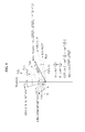
- FIGS. 2 through 4 are diagrams illustrating an example of a phase and a magnitude of two successive signals in an ensemble I/Q signal according to an exemplary embodiment of the present invention.
- a graph of modulated I/Q signals namely, a graph of E(0), E(1), E(2), E(3), ..., E(EL-2), and E(EL-1), is illustrated in FIGS. 2 through 4 , a number of the modulated I/Q signals being same as an ensemble length that is a number of pixels constructing an color image.
- a phase and a magnitude of two temporally successive I/Q signals may be calculated using the two signals.
- the ultrasound Doppler image system 100 may calculate a phase and a magnitude of E(0) and E(1) using the two temporally successive signals, namely, E(0) and E(1).
- the ultrasound color Doppler image system 100 may calculate a phase and a magnitude of temporally successive two signals, namely, E(1) and E(2) using E(1) and E(2).
- the ultrasound color Doppler image system 100 may continuously calculate a phase and a magnitude of each of two other signals, such as E(2) and E(3), E(3)and E(4), ..., and E(EL-3) and E(EL-2) in the same manner as described with reference to FIGS. 2 and 3 , and when a phase and a magnitude of E(EL-2) and E(EL-1) is calculated based on a method of FIG. 4 , phases and magnitudes of each pixel or each sample in an ensemble I/Q signal, namely the color image, are completely calculated.
- two other signals such as E(2) and E(3), E(3)and E(4), ..., and E(EL-3) and E(EL-2) in the same manner as described with reference to FIGS. 2 and 3 , and when a phase and a magnitude of E(EL-2) and E(EL-1) is calculated based on a method of FIG. 4 , phases and magnitudes of each pixel or each sample in an ensemble I/Q signal, namely the color image, are completely calculated.
- the ultrasound color Doppler image system 100 may calculate phases and a magnitudes of each pixel or each sample in the ensemble I/Q signal, namely, the color image, using two temporally successive signals. Accordingly, the ultrasound color Doppler image system 100 may calculate the mean phase and the mean magnitude as illustrated in FIG. 3 based on the phases and magnitudes calculated in FIGS. 2 through 4 .
- Meanphase denotes a mean phase
- MeanMagnitude denotes a mean magnitude
- n denotes a total number of phases and a total number of magnitudes
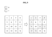
- FIG. 5 illustrates an example of masking a pixel in a color image according to an exemplary embodiment of the present invention.
- each square block denotes a pixel
- a number in the square block denotes a pixel number.
- numbers "0" and "1" in a right side of a black block and a white block denote a masking value.
- a masking value corresponding to pixel numbers 1, 2, 4, 5, 9, 11, 12, 13, and 14 is "0"
- a masking value corresponding to pixel numbers 3, 6, 7, 8, 10, 15, and 16 is "1".
- the ultrasound color Doppler image system 100 may perform masking of pixels masking values of which are "0", namely, the pixels corresponding to the pixel numbers 1, 2, 4, 5, 9, 11, 12, 13, and 14.
- the corresponding pixels are marked in oblique lines and the corresponding pixels may be marked in black when actually embodied.
- the ultrasound color Doppler image system may not perform masking of pixels masking values of which are "1 ", namely, the pixels corresponding to the pixel numbers 3, 6, 7, 8, 10, 15, and 16.
- the ultrasound color Doppler image system 100 may set the masking value through a process, such as calculation, comparison, and the like, with respect to each pixel of the color image, and may perform masking of a corresponding pixel according to a predetermined masking value. Accordingly, a flash artifact component may be effectively eliminated from a color Doppler image according to an exemplary embodiment of the present invention.
- the ultrasound color Doppler image system may effectively eliminate the flash artifact component from the color Doppler image, thereby providing a more accurate Doppler image as illustrated in FIG. 6 .
- FIG. 6 illustrates an image (left image) before eliminating a flash artifact from a color Doppler image and an image (right image) after eliminating the flash artifact from the color Doppler image according to an exemplary embodiment of the present invention.
- FIG. 7 illustrates a method of filtering a clutter signal in an ultrasound color Doppler image system according to an exemplary embodiment of the present invention.
- the ultrasound color Doppler image system 100 may calculate a mean phase and a mean magnitude of a first signal corresponding to a pixel of a color image in the ultrasound image in operation S710.
- the color image may be an image before a clutter signal is eliminated, namely, an image including a blood flow and a peripheral tissue, such as a vessel wall, a muscle, and the like.
- the first signal may be an I/Q signal per pixel or an I/Q signal per sample among an I/Q signal based on an ensemble unit.
- the ultrasound color Doppler image system may calculate a mean phase and a mean magnitude of the first signal using the first signal and a second signal that has a temporal continuity with the first signal.
- the ultrasound color Doppler image system 100 may generate a first multiplication value and a second multiplication value by multiplying each of a maximum value for the calculated mean phase and a maximum value for the calculated mean magnitude by a predetermined scale factor.
- the scale factor may be set by a user in advance, and may include positive numbers, such as 1, 1.5, 2, 2.5, and the like, as coefficients for scaling.
- the ultrasound color Doppler image system 100 may generate the first multiplication value by multiplying the scale factor and the maximum value for the calculated mean phase, namely a maximum mean phase (scale factor x maximum mean phase). Also, the ultrasound color Doppler image system may generate the second multiplication value by multiplying the scale factor and the maximum value for the calculated mean magnitude, namely a maximum mean magnitude (scale factor x maximum mean magnitude).
- the ultrasound color Doppler image system 100 may compare the generated first multiplication value and the generated second multiplication value with each of the mean phase and the mean magnitude.
- the ultrasound color Doppler image system 100 may compare the first multiplication value with the mean phase, and may compare the second multiplication value with the mean magnitude.
- the ultrasound color Doppler image system may perform masking of the corresponding pixel of the color image based on the comparison result in operation S740.
- the ultrasound color Doppler image system 100 may perform masking of the corresponding pixel of the color image.
- the ultrasound color Doppler image system 100 may perform masking of the corresponding pixel of the color image.
- the ultrasound color Doppler image system may perform masking of the corresponding pixel of the color image.
- the ultrasound color Doppler image system 100 may not perform masking of the corresponding pixel of the color image.
- the ultrasound color Doppler image system 100 may determine whether to perform the masking of each pixel in the color image through a calculation and a comparison, and may perform masking of a corresponding pixel. Accordingly, example embodiments may effectively eliminate a flash artifact component from the color Doppler image by filtering a clutter signal from a Doppler signal.
- the exemplary embodiments of the present invention include computer-readable media including program instructions to implement various operations embodied by a computer.
- the media may also include, alone or in combination with the program instructions, data files, data structures, tables, and the like.
- the media and program instructions may be those specially designed and constructed for the purposes of the present invention, or they may be of the kind well known and available to those having skill in the computer software arts.
- Examples of computer-readable media include magnetic media such as hard disks, floppy disks, and magnetic tape; optical media such as CD ROM disks; magneto-optical media such as optical disks; and hardware devices that are specially configured to store and perform program instructions, such as read-only memory devices (ROM) and random access memory (RAM).
- Examples of program instructions include both machine code, such as produced by a compiler, and files containing higher level code that may be executed by the computer using an interpreter.
- the described hardware devices may be configured to act as one or more software modules in order to perform the operations of the above-described embodiments of the present invention, or vice versa.
Landscapes
- Physics & Mathematics (AREA)
- Engineering & Computer Science (AREA)
- Remote Sensing (AREA)
- Radar, Positioning & Navigation (AREA)
- Acoustics & Sound (AREA)
- Health & Medical Sciences (AREA)
- Life Sciences & Earth Sciences (AREA)
- General Physics & Mathematics (AREA)
- Computer Networks & Wireless Communication (AREA)
- Pathology (AREA)
- Public Health (AREA)
- Medical Informatics (AREA)
- Molecular Biology (AREA)
- Surgery (AREA)
- Animal Behavior & Ethology (AREA)
- General Health & Medical Sciences (AREA)
- Heart & Thoracic Surgery (AREA)
- Veterinary Medicine (AREA)
- Biomedical Technology (AREA)
- Radiology & Medical Imaging (AREA)
- Nuclear Medicine, Radiotherapy & Molecular Imaging (AREA)
- Biophysics (AREA)
- Hematology (AREA)
- Ultra Sonic Daignosis Equipment (AREA)
Abstract
Description
- This application claims the benefit of Korean Patent Application No.
10-2009-0118439, filed on December 2, 2009 - The present invention relates to an ultrasound color Doppler image system, and more specifically, to an ultrasound color Doppler image system that filters a clutter signal from a color Doppler image.
- An ultrasound color Doppler image system may emit an ultrasound to a human body and may measure a Doppler shift frequency of the ultrasound reflected from a blood flow, thereby detecting a distribution of the blood flow in a real time.
- Although the emitted ultrasound is well focused on the blood flow, a part of the ultrasound may be emitted in an undesired direction, and thus, a reflection signal reflected from the blood flow may be returned together with an undesired signal reflected from other tissue besides the blood flow. In this instance, the reflection signal from the blood flow is referred to as a Doppler signal, and the undesired signal reflected from other tissue is referred to as a clutter signal.
- Usually, when the ultrasound is well focused, most of ultrasound energy may be transmitted to a focal point, and a relatively small portion of the ultrasound energy may leak to the outside, and thus, a desired signal from the focal point may be mostly returned. However a reflectivity of blood flow is relatively small compared with a reflectivity of peripheral tissue, such as a vessel wall, a muscle, and the like, and thus, in general, the clutter signal is greater than the Doppler signal even though a relatively small amount of ultrasound energy generally leaks.
- When there is little movement of the peripheral tissue, a Doppler shift frequency is relatively close to zero, and thus, it is generally well-known that the clutter signal is easily eliminated by a high-pass clutter filter. Also, when movement of the peripheral tissue becomes faster, the Doppler shift frequency of the clutter signal may increase. Accordingly, the clutter signal may not be completely eliminated with a general clutter filter, and thus, an aberrant color may appear on a screen. The fast movement of the tissue may be displayed as though the fast movement is the blood flow. The aberrant color is an artifact displayed on the screen, and the artifact may appear as an instantaneous flash on the screen, thereby being referred to as a flash artifact.
- An aspect of the present invention provides an apparatus and a method that filters a clutter signal to eliminate a flash artifact component from a color Doppler image.
- Another aspect of the present invention provides an apparatus and a method that eliminates a clutter signal from both a wideband frequency, and a narrowband frequency.
- According to exemplary embodiments of the present invention, there may be provided an ultrasound color Doppler image system, the system including a calculation unit to calculate a mean value associated with an I/Q signal corresponding to a pixel of a color image in an ultrasound image, and to generate a multiplication value using the calculated mean value, a comparison unit to compare the generated multiplication value with the mean value, and a masking unit to perform masking of the pixel based on a comparison result.
- The calculation unit may calculate the mean value of the I/Q signal for each frame, may select a reference mean value based on scales of the calculated mean values, and may generate the multiplication value by multiplying the selected reference mean value and a scale factor.
- According to exemplary embodiments of the present invention, there may be provided a method of filtering a clutter signal in an ultrasound color Doppler image system, the method including calculating a mean value associated with an I/Q signal corresponding to a pixel of a color image in an ultrasound image, generating a multiplication value using the calculated mean value, comparing the generated multiplication value with the mean value, and performing a masking of the pixel based on a comparison result.
- The calculating may calculate the mean value of the I/Q signal for each frame. The generating of the multiplication value may select a reference mean value based on scales of calculated mean values; and may generate the multiplication value by multiplying the selected reference mean value and a scale factor.
- Additional aspects and/or advantages will be set forth in part in the description which follows and, in part, will be apparent from the description, or may be learned by practice of the embodiments.
- According to exemplary embodiments of the present invention, a clutter signal is filtered, and thus, a flash artifact component is eliminated from a color Doppler image.
- According to exemplary embodiments of the present invention, a clutter signal is eliminated from both a wideband frequency, and a narrowband frequency.
- These and/or other aspects and advantages will become apparent and more readily appreciated from the following description of the embodiments, taken in conjunction with the accompanying drawings of which:
-
FIG. 1 is a block diagram illustrating an ultrasound color Doppler image system according to an exemplary embodiment of the present invention; -
FIGS. 2 through 4 are diagrams illustrating an example of an phase and a magnitude of two successive signals in an ensemble I/Q signal according to an exemplary embodiment of the present invention; -
FIG. 5 is a diagram illustrating an example of masking a pixel in a color image according to an exemplary embodiment of the present invention; -
FIG. 6 is a diagram illustrating an image before eliminating a flash artifact from a color Doppler image and an image after eliminating the flash artifact from the color Doppler image according to an exemplary embodiment of the present invention; and -
FIG. 7 is a flowchart illustrating a method of filtering a clutter signal in an ultrasound color Doppler image system according to an exemplary embodiment of the present invention. - Reference will now be made in detail to example embodiments, examples of which are illustrated in the accompanying drawings, wherein like reference numerals refer to the like elements throughout. An ultrasound diagnosis apparatus utilizing a touch interaction is described below to explain the present disclosure by referring to the figures.
-
FIG. 1 illustrates an ultrasound color Doppler image system according to an exemplary embodiment of the present invention. - Referring to
FIG. 1 , an ultrasound colorDoppler image system 100 may include acalculation unit 110, acomparison unit 120, amasking unit 130, and acontroller 140. - The
calculation unit 110 may calculate a mean phase and a mean magnitude of a first signal corresponding to a pixel of a color image in an ultrasound image. Here, the color image may be an image before a clutter signal is eliminated, namely, an image including a blood flow and a peripheral tissue, such as a vessel wall, muscle, and the like. Also, the first signal may be an In-phase/Quadrature-phase signal (I/Q signal) per pixel or an I/Q signal per sample among an I/Q signal based on an ensemble unit or I/Q signal based on a frame unit. - In this instance, the
calculation unit 110 may calculate the mean phase and the mean magnitude of the first signal (an I/Q signal) using a second signal (another I/Q signal) that has a temporal continuity with the first signal (the I/Q signal). As an example, when thecalculation unit 110 calculates the mean phase and the mean magnitude of the first signal based onEquation 1 may be as given below: [Equation 1]

- Here, MeanPhase denotes the mean phase, MeanMagn denotes the mean magnitude, i denotes a scanline number, j denotes a sample number or a pixel number, k denotes an ensemble number, EL denotes a length of ensemble, * denotes a conjugated complex number, and E(k,i,j) denotes a modulated I/Q signal that is expressed in a form of a complex number (i+jQ).
- The
calculation unit 110 may generate a first multiplication value and a second multiplication value by multiplying a predetermined scale factor and each of a maximum value for the calculated mean phase and a maximum value for the calculated mean magnitude. Here, the scale factor may be set in advance depending on a user or a system environment. - Specifically, the
calculation unit 110 may generate the first multiplication value by multiplying the maximum value for the mean phase, namely, a maximum mean phase, by the scale factor. Also, thecalculation unit 110 may generate the second multiplication value by multiplying the maximum value for the mean magnitude, namely a maximum mean magnitude, by the scale factor. - The
calculation unit 110 may calculate the maximum value for the calculated mean phase and the maximum value for the calculated mean magnitude based on an example, such asEquation 2 as given below. Thecalculation unit 110 may compare mean phases with each other to calculate the maximum value for the mean phase, and may compare mean magnitudes with each other to calculate the maximum value for the mean magnitude. [Equation 2]

- Here, MaxPhase denotes the maximum value for the mean phase, MaxMagn denotes the maximum value for the mean magnitute, i denotes a scanline number, j denotes a sample number or a pixel number, I denotes a maximum value for the scaneline, J denotes a maximum value for the sample number or the pixel number, MeanPhase denotes a mean phase, and MeanMagn denotes a mean magnitude.
- For reference, the ultrasound color
Doppler image system 100 may perform modulation based on a pixel unit with respect to all pixels in an I/Q signal based on an ensemble unit, before performing calculation by thecalculation unit 110. Accordingly, the first signal may be modulated signal. - The
comparison unit 120 may compare the generated first multiplication value, the generated second multiplication value with the calculated mean magnitude and the calculated mean phase, respectively. Specifically, thecomparison unit 120 may compare the generated first multiplication value with the calculated mean phase, and may compare the generated second multiplication value with the calculated mean magnitude. - The
masking unit 130 may perform masking of the corresponding pixel of the color image based on a comparison result. - As an example, when the first multiplication value is less than the mean phase and the second multiplication value is greater than the mean magnitude according to the comparison result (first multiplication value < mean phase & second multiplication value > mean magnitude), the
masking unit 130 may perform masking of the corresponding pixel of the color image. - Also, when the first multiplication value is greater than the mean phase, and the second multiplication value is greater than the mean magnitude according to the comparison result (first multiplication value > mean phase & second multiplication value > mean magnitude), the
masking unit 130 may perform masking of the corresponding pixel of the color image. - Also, when the first multiplication value is less than the mean phase, and the second multiplication value is less than the mean magnitude according to the comparison result (first multiplication value < mean phase & second multiplication value < mean magnitude), the
masking unit 130 may perform masking of the corresponding pixel of the color image. - Conversely, when the first multiplication value is greater than the mean phase and the second multiplication value is less than the mean magnitude according to the comparison result (first multiplication value > mean phase & second multiplication value < mean magnitude), the
masking unit 130 may not perform masking of the corresponding pixel of the color image. - This may be simply shown by Table 1 as given below:
[Table 1] Comparison between first multiplication value with mean phase Comparison between second multiplication value with mean magnitude Making value 1 mean phase < scale factor x max mean phase & mean magnitude > scale factor x max mean magnitude 0 (Masking) 2 mean phase > scale factor x max mean phase & mean magnitude < scale factor x max mean magnitude 1 (No Masking) 3 mean phase > scale factor x max mean phase & mean magnitude > scale factor x max mean magnitude 0 (Masking) 4 mean phase < scale factor x max mean phase & mean magnitude < scale factor x max mean magnitude 0 (Masking) - As shown in Table 1, the ultrasound color
Doppler image system 100 may set a masking value as "0" or "1" depending on the comparison result between the first multiplication value and the mean phase and the comparison result between the second multiplication value and the mean magnitude. Accordingly, themasking unit 130 may perform masking of the corresponding pixel of the color image, when the masking value is "0". Conversely, themasking unit 130 may not perform masking of the corresponding pixel of the color image, when the masking value is "1". - The
controller 140 may generally control an operation of the ultrasound colorDoppler image system 100, such as operations of thecalculation unit 110, thecomparison unit 120, themasking unit 130, and the like. -
FIGS. 2 through 4 are diagrams illustrating an example of a phase and a magnitude of two successive signals in an ensemble I/Q signal according to an exemplary embodiment of the present invention. - A graph of modulated I/Q signals, namely, a graph of E(0), E(1), E(2), E(3), ..., E(EL-2), and E(EL-1), is illustrated in
FIGS. 2 through 4 , a number of the modulated I/Q signals being same as an ensemble length that is a number of pixels constructing an color image. A phase and a magnitude of two temporally successive I/Q signals may be calculated using the two signals. - First, as illustrated in
FIG. 2 , the ultrasoundDoppler image system 100 according to an exemplary embodiment of the present invention may calculate a phase and a magnitude of E(0) and E(1) using the two temporally successive signals, namely, E(0) and E(1). - Specifically, the ultrasound color
Doppler image system 100 may multiply the two temporally successive signals, namely, E(0) and E(1), (E(0) X E(1)*), and may calculate a phase (C(0)=


- As illustrated in
FIG. 3 , the ultrasound colorDoppler image system 100 may calculate a phase and a magnitude of temporally successive two signals, namely, E(1) and E(2) using E(1) and E(2). - Specifically, the ultrasound color
Doppler image system 100 may multiply the two temporally successive signals, namely, E(1) and E(2), (E(1) X E(2*), and may calculate a phase (C(1) =

multiplication result 
- The ultrasound color
Doppler image system 100 may continuously calculate a phase and a magnitude of each of two other signals, such as E(2) and E(3), E(3)and E(4), ..., and E(EL-3) and E(EL-2) in the same manner as described with reference toFIGS. 2 and3 , and when a phase and a magnitude of E(EL-2) and E(EL-1) is calculated based on a method ofFIG. 4 , phases and magnitudes of each pixel or each sample in an ensemble I/Q signal, namely the color image, are completely calculated. - As illustrated in
FIG. 4 , the ultrasound colorDoppler image system 100 may multiply two temporally successive signals, namely, E(EL-2) and E(EL-1), ((E(EL-2) x E(EL-1)*), and may calculate a phase (C(EL-2)=

multiplication result 
- As described above, the ultrasound color
Doppler image system 100 may calculate phases and a magnitudes of each pixel or each sample in the ensemble I/Q signal, namely, the color image, using two temporally successive signals. Accordingly, the ultrasound colorDoppler image system 100 may calculate the mean phase and the mean magnitude as illustrated inFIG. 3 based on the phases and magnitudes calculated inFIGS. 2 through 4 . [Equation 3]

- Here, Meanphase denotes a mean phase, MeanMagnitude denotes a mean magnitude, n denotes a total number of phases and a total number of magnitudes,


-
FIG. 5 illustrates an example of masking a pixel in a color image according to an exemplary embodiment of the present invention. For reference, inFIG. 5 , each square block denotes a pixel, and a number in the square block denotes a pixel number. Also, numbers "0" and "1" in a right side of a black block and a white block denote a masking value. - As illustrated in
FIG. 5 , a masking value corresponding topixel numbers pixel numbers - Accordingly, the ultrasound color
Doppler image system 100 may perform masking of pixels masking values of which are "0", namely, the pixels corresponding to thepixel numbers - Conversely, the ultrasound color Doppler image system may not perform masking of pixels masking values of which are "1 ", namely, the pixels corresponding to the
pixel numbers - As described above, the ultrasound color
Doppler image system 100 may set the masking value through a process, such as calculation, comparison, and the like, with respect to each pixel of the color image, and may perform masking of a corresponding pixel according to a predetermined masking value. Accordingly, a flash artifact component may be effectively eliminated from a color Doppler image according to an exemplary embodiment of the present invention. - As described above, the ultrasound color Doppler image system may effectively eliminate the flash artifact component from the color Doppler image, thereby providing a more accurate Doppler image as illustrated in
FIG. 6 . For reference,FIG. 6 illustrates an image (left image) before eliminating a flash artifact from a color Doppler image and an image (right image) after eliminating the flash artifact from the color Doppler image according to an exemplary embodiment of the present invention. -
FIG. 7 illustrates a method of filtering a clutter signal in an ultrasound color Doppler image system according to an exemplary embodiment of the present invention. - Referring to
FIG. 7 , the ultrasound colorDoppler image system 100 may calculate a mean phase and a mean magnitude of a first signal corresponding to a pixel of a color image in the ultrasound image in operation S710. Here, the color image may be an image before a clutter signal is eliminated, namely, an image including a blood flow and a peripheral tissue, such as a vessel wall, a muscle, and the like. Also, the first signal may be an I/Q signal per pixel or an I/Q signal per sample among an I/Q signal based on an ensemble unit. - In this instance, the ultrasound color Doppler image system may calculate a mean phase and a mean magnitude of the first signal using the first signal and a second signal that has a temporal continuity with the first signal.
- Subsequently, the ultrasound color
Doppler image system 100 may generate a first multiplication value and a second multiplication value by multiplying each of a maximum value for the calculated mean phase and a maximum value for the calculated mean magnitude by a predetermined scale factor. Here, the scale factor may be set by a user in advance, and may include positive numbers, such as 1, 1.5, 2, 2.5, and the like, as coefficients for scaling. - Specifically, the ultrasound color
Doppler image system 100 may generate the first multiplication value by multiplying the scale factor and the maximum value for the calculated mean phase, namely a maximum mean phase (scale factor x maximum mean phase). Also, the ultrasound color Doppler image system may generate the second multiplication value by multiplying the scale factor and the maximum value for the calculated mean magnitude, namely a maximum mean magnitude (scale factor x maximum mean magnitude). - Subsequently, the ultrasound color
Doppler image system 100 may compare the generated first multiplication value and the generated second multiplication value with each of the mean phase and the mean magnitude. - Specifically, the ultrasound color
Doppler image system 100 may compare the first multiplication value with the mean phase, and may compare the second multiplication value with the mean magnitude. - Subsequently, the ultrasound color Doppler image system may perform masking of the corresponding pixel of the color image based on the comparison result in operation S740.
- As an example, when the first multiplication value is less than the mean phase and the second multiplication value is greater than the mean magnitude according to the comparison result (first multiplication value < mean phase & second multiplication value > mean magnitude), the ultrasound color
Doppler image system 100 may perform masking of the corresponding pixel of the color image. - When the first multiplication value is greater than the mean phase, and the second multiplication value is greater than the mean magnitude according to the comparison result (first multiplication value > mean phase & second multiplication value > mean magnitude), the ultrasound color
Doppler image system 100 may perform masking of the corresponding pixel of the color image. - When the first multiplication value is less than the mean phase, and the second multiplication value is less than the mean magnitude according to the comparison result (first multiplication value < mean phase & second multiplication value < mean magnitude), the ultrasound color Doppler image system may perform masking of the corresponding pixel of the color image.
- Conversely, when the first multiplication value is greater than the mean phase, and the second multiplication value is less than the mean magnitude according to the comparison result (first multiplication value > mean phase & second multiplication mean magnitude), the ultrasound color
Doppler image system 100 may not perform masking of the corresponding pixel of the color image. - As described above, the ultrasound color
Doppler image system 100 may determine whether to perform the masking of each pixel in the color image through a calculation and a comparison, and may perform masking of a corresponding pixel. Accordingly, example embodiments may effectively eliminate a flash artifact component from the color Doppler image by filtering a clutter signal from a Doppler signal. - The exemplary embodiments of the present invention include computer-readable media including program instructions to implement various operations embodied by a computer. The media may also include, alone or in combination with the program instructions, data files, data structures, tables, and the like. The media and program instructions may be those specially designed and constructed for the purposes of the present invention, or they may be of the kind well known and available to those having skill in the computer software arts. Examples of computer-readable media include magnetic media such as hard disks, floppy disks, and magnetic tape; optical media such as CD ROM disks; magneto-optical media such as optical disks; and hardware devices that are specially configured to store and perform program instructions, such as read-only memory devices (ROM) and random access memory (RAM). Examples of program instructions include both machine code, such as produced by a compiler, and files containing higher level code that may be executed by the computer using an interpreter. The described hardware devices may be configured to act as one or more software modules in order to perform the operations of the above-described embodiments of the present invention, or vice versa.
- Although a few example embodiments have been shown and described, it would be appreciated by those skilled in the art that changes may be made in these example embodiments without departing from the principles and spirit of the invention, the scope of which is defined in the claims and their equivalents.
Claims (11)
- An ultrasound color Doppler image system, the system comprising:a calculation unit to calculate, for each frame, a mean value associated with an I/Q signal corresponding to a pixel of a color image in an ultrasound image, and to generate a multiplication value using the calculated mean value;a comparison unit to compare the generated multiplication value with the mean value; anda masking unit to perform masking of the pixel based on a comparison result,wherein the calculation unit calculates the mean value of the I/Q signal for each frame, selects a reference mean value based on scales of the calculated mean values, and generates the multiplication value by multiplying the selected reference mean value and a scale factor.
- The system of claim 1, wherein the calculation unit calculates a mean phase and a mean magnitude as the mean value, generates a first multiplication value associated with the mean phase, and generates a second multiplication value associated with the mean magnitude.
- The system of claim 2, wherein the comparison unit performs:comparing the first multiplication value with a mean phase calculated for a frame that is a target of the masking; andcomparing the second multiplication value with a mean magnitude calculated for the frame that is the target of the masking.
- The system of claim 2, wherein the masking unit performs the masking of the pixel for the frame that is the target of the masking, when a case corresponds to one of a case:(1) where the first multiplication value is less than the mean phase, and the second multiplication value is greater than the mean magnitude;(2) where the first multiplication value is greater than the mean phase, and the second multiplication value is greater than the mean magnitude as a result of the comparison; and(3) where the first multiplication value is less than the mean phase and the second multiplication value is less that the mean magnitude.
- The system of claim 2, wherein the calculation unit calculates the mean phase and the mean magnitude based on the I/Q signal and another I/Q signal having a temporal continuity with the I/Q signal.
- A method of filtering a clutter signal in an ultrasound color Doppler image system, the method comprising:calculating, for each frame, a mean value associated with I/Q signal corresponding to a pixel of a color image in an ultrasound image;generating a multiplication value using the calculated mean value;comparing the generated multiplication value with the mean value; andperforming a masking of the pixel based on a comparison result,wherein the generating of the multiplication value performs:selecting a reference mean value based on scales of calculated mean values; andgenerating the multiplication value by multiplying the selected reference mean value and a scale factor.
- The method of claim 6, wherein, when a mean phase and a mean magnitude are calculated as the mean value, the generating further comprises:generating a first multiplication value associated with the mean phase and a second multiplication value associated with the mean magnitude.
- The method of claim 7, wherein the comparing comprises:comparing the first multiplication value with a mean phase for a frame that is a target of the masking; andcomparing the second multiplication value with a mean magnitude for the frame that is the target of the masking.
- The method of claim 7, wherein the masking performs the masking of the pixel for the frame that is the target of the masking, when a case corresponds to one of a case:(1) where the first multiplication value is less than the mean phase, and the second multiplication value is greater than the mean magnitude;(2) where the first multiplication value is greater than the mean phase, and the second multiplication value is greater than the mean magnitude as a result of the comparison; and(3) where the first multiplication value is less than the mean phase and the second multiplication value is less that the mean magnitude.
- The method of claim 7, wherein the calculating of the mean value calculates the mean phase and the mean magnitude based on the I/Q signal and another I/Q signal having a temporal continuity with the I/Q signal.
- A computer readable recording medium storing a program implementing the method of claim 6.
Applications Claiming Priority (1)
| Application Number | Priority Date | Filing Date | Title |
|---|---|---|---|
| KR1020090118439A KR101029407B1 (en) | 2009-12-02 | 2009-12-02 | Ultrasonic Color Doppler Imaging System and Clutter Signal Filtering Method of Ultrasonic Color Doppler Imaging System |
Publications (2)
| Publication Number | Publication Date |
|---|---|
| EP2333579A2 true EP2333579A2 (en) | 2011-06-15 |
| EP2333579A3 EP2333579A3 (en) | 2013-06-19 |
Family
ID=43733955
Family Applications (1)
| Application Number | Title | Priority Date | Filing Date |
|---|---|---|---|
| EP10188449.2A Withdrawn EP2333579A3 (en) | 2009-12-02 | 2010-10-22 | Ultrasound color Doppler imaging system and method for filtering clutter signal of the same |
Country Status (4)
| Country | Link |
|---|---|
| US (1) | US8758250B2 (en) |
| EP (1) | EP2333579A3 (en) |
| JP (1) | JP5697959B2 (en) |
| KR (1) | KR101029407B1 (en) |
Families Citing this family (3)
| Publication number | Priority date | Publication date | Assignee | Title |
|---|---|---|---|---|
| US9658331B2 (en) * | 2012-11-23 | 2017-05-23 | Carestream Health, Inc. | Synthetic aperture doppler ultrasound methods and apparatus |
| JP6911710B2 (en) * | 2017-10-31 | 2021-07-28 | コニカミノルタ株式会社 | Ultrasound diagnostic equipment, ultrasonic image generation method and program |
| KR102648307B1 (en) | 2018-02-20 | 2024-03-15 | 삼성메디슨 주식회사 | Method and ultrasound diagnostic apparatus for displaying a doppler image |
Family Cites Families (16)
| Publication number | Priority date | Publication date | Assignee | Title |
|---|---|---|---|---|
| JP2742947B2 (en) * | 1989-04-28 | 1998-04-22 | ジーイー横河メディカルシステム株式会社 | Ultrasound blood flow imaging device |
| JPH088920B2 (en) * | 1990-09-28 | 1996-01-31 | 富士通株式会社 | Blood scattering power calculator |
| AU4523796A (en) * | 1994-12-30 | 1996-07-24 | Acuson Corporation | Imaging modality showing energy and velocity |
| US5588202A (en) * | 1995-03-17 | 1996-12-31 | Honeywell Inc. | Method for manufacturing an overmolded sensor |
| US6511426B1 (en) * | 1998-06-02 | 2003-01-28 | Acuson Corporation | Medical diagnostic ultrasound system and method for versatile processing |
| US6296612B1 (en) | 1999-07-09 | 2001-10-02 | General Electric Company | Method and apparatus for adaptive wall filtering in spectral Doppler ultrasound imaging |
| US6733455B2 (en) * | 1999-08-20 | 2004-05-11 | Zonare Medical Systems, Inc. | System and method for adaptive clutter filtering in ultrasound color flow imaging |
| US6760486B1 (en) * | 2000-03-28 | 2004-07-06 | General Electric Company | Flash artifact suppression in two-dimensional ultrasound imaging |
| US6312385B1 (en) * | 2000-05-01 | 2001-11-06 | Ge Medical Systems Global Technology Company, Llc | Method and apparatus for automatic detection and sizing of cystic objects |
| US6606252B1 (en) * | 2002-07-17 | 2003-08-12 | Delphi Technologies, Inc. | Fastener detection for encased electrical assembly |
| TWM250504U (en) * | 2003-11-27 | 2004-11-11 | Optimum Care Int Tech Inc | Assembly structure for hiding electronic component |
| JP2005318920A (en) * | 2004-05-06 | 2005-11-17 | Aloka Co Ltd | Ultrasonic diagnostic equipment |
| US7772974B2 (en) * | 2005-02-28 | 2010-08-10 | Cypak Ab | Tamper evident seal system and method |
| EP2173253A2 (en) * | 2007-07-26 | 2010-04-14 | Koninklijke Philips Electronics N.V. | Systems and methods for automated image selection in doppler ultrasound imaging systems |
| US8098910B2 (en) * | 2007-09-11 | 2012-01-17 | Siemens Medical Solutions Usa, Inc. | Adaptive motion imaging in medical diagnostic ultrasound imaging |
| KR101100551B1 (en) * | 2008-12-17 | 2011-12-29 | 삼성메디슨 주식회사 | Ultrasound system and method for filtering clutter signals |
-
2009
- 2009-12-02 KR KR1020090118439A patent/KR101029407B1/en active Active
-
2010
- 2010-10-22 EP EP10188449.2A patent/EP2333579A3/en not_active Withdrawn
- 2010-11-30 JP JP2010267203A patent/JP5697959B2/en not_active Expired - Fee Related
- 2010-12-02 US US12/959,030 patent/US8758250B2/en active Active
Non-Patent Citations (1)
| Title |
|---|
| None |
Also Published As
| Publication number | Publication date |
|---|---|
| JP2011115587A (en) | 2011-06-16 |
| US8758250B2 (en) | 2014-06-24 |
| US20110137174A1 (en) | 2011-06-09 |
| EP2333579A3 (en) | 2013-06-19 |
| JP5697959B2 (en) | 2015-04-08 |
| KR101029407B1 (en) | 2011-04-14 |
Similar Documents
| Publication | Publication Date | Title |
|---|---|---|
| US6368277B1 (en) | Dynamic measurement of parameters within a sequence of images | |
| US11523774B2 (en) | Tissue property estimation with ultrasound medical imaging | |
| US7780601B2 (en) | Adaptive clinical marker preservation in spatial compound ultrasound imaging | |
| US6659953B1 (en) | Morphing diagnostic ultrasound images for perfusion assessment | |
| US8425422B2 (en) | Adaptive volume rendering for ultrasound color flow diagnostic imaging | |
| US10512450B2 (en) | Shear wave estimation from analytic data | |
| JP6385992B2 (en) | Detection of sparkle artifacts in ultrasonic color flow | |
| US8801614B2 (en) | On-axis shear wave characterization with ultrasound | |
| US10456115B2 (en) | Ultrasound system and clutter filtering method thereof | |
| US11553901B2 (en) | Liver disease activity estimation with ultrasound medical imaging | |
| US20160228096A1 (en) | Ultrasound ARFI Displacement Imaging Using an Adaptive Time Instance | |
| US20080294049A1 (en) | Targeted contrast agent imaging with medical diagnostic ultrasound | |
| KR20000035616A (en) | Three-dimensional ultrasound imaging of velocity and power data using average or median pixel projections | |
| US6858010B2 (en) | Identifying clinical markers in spatial compounding ultrasound imaging | |
| EP3278734B1 (en) | Beamforming device, ultrasonic imaging device, and beamforming method allowing simple spatial smoothing operation | |
| US20120155727A1 (en) | Method and apparatus for providing motion-compensated images | |
| JP2020523143A (en) | Method and system for processing ultrasound images | |
| US20090069675A1 (en) | Adaptive motion imaging in medical diagnostic ultrasound imaging | |
| US12533112B2 (en) | Tissue property estimation with ultrasound medical imaging | |
| US8758250B2 (en) | Ultrasound color Doppler imaging system and method for filtering clutter signal of the same | |
| KR20210116268A (en) | Liver disease activity estimation with ultrasound medical imaging | |
| CN115869005B (en) | Interference suppression method for ultrasonic image, ultrasonic device and storage medium | |
| US11141138B2 (en) | Kalman filtering for flash artifact suppression in ultrasound imaging | |
| CN111511286B (en) | Ultrasound Measurement of Vascular Stenosis | |
| JP2020523149A (en) | Method and system for processing ultrasound images |
Legal Events
| Date | Code | Title | Description |
|---|---|---|---|
| PUAI | Public reference made under article 153(3) epc to a published international application that has entered the european phase |
Free format text: ORIGINAL CODE: 0009012 |
|
| AK | Designated contracting states |
Kind code of ref document: A2 Designated state(s): AL AT BE BG CH CY CZ DE DK EE ES FI FR GB GR HR HU IE IS IT LI LT LU LV MC MK MT NL NO PL PT RO RS SE SI SK SM TR |
|
| AX | Request for extension of the european patent |
Extension state: BA ME |
|
| RAP1 | Party data changed (applicant data changed or rights of an application transferred) |
Owner name: SAMSUNG MEDISON CO., LTD. |
|
| PUAL | Search report despatched |
Free format text: ORIGINAL CODE: 0009013 |
|
| AK | Designated contracting states |
Kind code of ref document: A3 Designated state(s): AL AT BE BG CH CY CZ DE DK EE ES FI FR GB GR HR HU IE IS IT LI LT LU LV MC MK MT NL NO PL PT RO RS SE SI SK SM TR |
|
| AX | Request for extension of the european patent |
Extension state: BA ME |
|
| RIC1 | Information provided on ipc code assigned before grant |
Ipc: G01S 15/89 20060101AFI20130515BHEP |
|
| 17P | Request for examination filed |
Effective date: 20131218 |
|
| RBV | Designated contracting states (corrected) |
Designated state(s): AL AT BE BG CH CY CZ DE DK EE ES FI FR GB GR HR HU IE IS IT LI LT LU LV MC MK MT NL NO PL PT RO RS SE SI SK SM TR |
|
| 17Q | First examination report despatched |
Effective date: 20161208 |
|
| STAA | Information on the status of an ep patent application or granted ep patent |
Free format text: STATUS: THE APPLICATION IS DEEMED TO BE WITHDRAWN |
|
| 18D | Application deemed to be withdrawn |
Effective date: 20180313 |