EP2333564A1 - Servogesteuertes bistatisches Staurohr - Google Patents
Servogesteuertes bistatisches Staurohr Download PDFInfo
- Publication number
- EP2333564A1 EP2333564A1 EP10194184A EP10194184A EP2333564A1 EP 2333564 A1 EP2333564 A1 EP 2333564A1 EP 10194184 A EP10194184 A EP 10194184A EP 10194184 A EP10194184 A EP 10194184A EP 2333564 A1 EP2333564 A1 EP 2333564A1
- Authority
- EP
- European Patent Office
- Prior art keywords
- optical axis
- optical
- measurement
- backscattered
- called
- Prior art date
- Legal status (The legal status is an assumption and is not a legal conclusion. Google has not performed a legal analysis and makes no representation as to the accuracy of the status listed.)
- Withdrawn
Links
Images


Classifications
-
- G—PHYSICS
- G01—MEASURING; TESTING
- G01P—MEASURING LINEAR OR ANGULAR SPEED, ACCELERATION, DECELERATION, OR SHOCK; INDICATING PRESENCE, ABSENCE, OR DIRECTION, OF MOVEMENT
- G01P5/00—Measuring speed of fluids, e.g. of air stream; Measuring speed of bodies relative to fluids, e.g. of ship, of aircraft
- G01P5/26—Measuring speed of fluids, e.g. of air stream; Measuring speed of bodies relative to fluids, e.g. of ship, of aircraft by measuring the direct influence of the streaming fluid on the properties of a detecting optical wave
-
- G—PHYSICS
- G01—MEASURING; TESTING
- G01S—RADIO DIRECTION-FINDING; RADIO NAVIGATION; DETERMINING DISTANCE OR VELOCITY BY USE OF RADIO WAVES; LOCATING OR PRESENCE-DETECTING BY USE OF THE REFLECTION OR RERADIATION OF RADIO WAVES; ANALOGOUS ARRANGEMENTS USING OTHER WAVES
- G01S17/00—Systems using the reflection or reradiation of electromagnetic waves other than radio waves, e.g. lidar systems
- G01S17/003—Bistatic lidar systems; Multistatic lidar systems
-
- G—PHYSICS
- G01—MEASURING; TESTING
- G01S—RADIO DIRECTION-FINDING; RADIO NAVIGATION; DETERMINING DISTANCE OR VELOCITY BY USE OF RADIO WAVES; LOCATING OR PRESENCE-DETECTING BY USE OF THE REFLECTION OR RERADIATION OF RADIO WAVES; ANALOGOUS ARRANGEMENTS USING OTHER WAVES
- G01S3/00—Direction-finders for determining the direction from which infrasonic, sonic, ultrasonic, or electromagnetic waves, or particle emission, not having a directional significance, are being received
- G01S3/78—Direction-finders for determining the direction from which infrasonic, sonic, ultrasonic, or electromagnetic waves, or particle emission, not having a directional significance, are being received using electromagnetic waves other than radio waves
- G01S3/782—Systems for determining direction or deviation from predetermined direction
- G01S3/783—Systems for determining direction or deviation from predetermined direction using amplitude comparison of signals derived from static detectors or detector systems
- G01S3/784—Systems for determining direction or deviation from predetermined direction using amplitude comparison of signals derived from static detectors or detector systems using a mosaic of detectors
-
- G—PHYSICS
- G01—MEASURING; TESTING
- G01S—RADIO DIRECTION-FINDING; RADIO NAVIGATION; DETERMINING DISTANCE OR VELOCITY BY USE OF RADIO WAVES; LOCATING OR PRESENCE-DETECTING BY USE OF THE REFLECTION OR RERADIATION OF RADIO WAVES; ANALOGOUS ARRANGEMENTS USING OTHER WAVES
- G01S3/00—Direction-finders for determining the direction from which infrasonic, sonic, ultrasonic, or electromagnetic waves, or particle emission, not having a directional significance, are being received
- G01S3/78—Direction-finders for determining the direction from which infrasonic, sonic, ultrasonic, or electromagnetic waves, or particle emission, not having a directional significance, are being received using electromagnetic waves other than radio waves
- G01S3/782—Systems for determining direction or deviation from predetermined direction
- G01S3/785—Systems for determining direction or deviation from predetermined direction using adjustment of orientation of directivity characteristics of a detector or detector system to give a desired condition of signal derived from that detector or detector system
- G01S3/786—Systems for determining direction or deviation from predetermined direction using adjustment of orientation of directivity characteristics of a detector or detector system to give a desired condition of signal derived from that detector or detector system the desired condition being maintained automatically
-
- G—PHYSICS
- G01—MEASURING; TESTING
- G01S—RADIO DIRECTION-FINDING; RADIO NAVIGATION; DETERMINING DISTANCE OR VELOCITY BY USE OF RADIO WAVES; LOCATING OR PRESENCE-DETECTING BY USE OF THE REFLECTION OR RERADIATION OF RADIO WAVES; ANALOGOUS ARRANGEMENTS USING OTHER WAVES
- G01S17/00—Systems using the reflection or reradiation of electromagnetic waves other than radio waves, e.g. lidar systems
- G01S17/02—Systems using the reflection of electromagnetic waves other than radio waves
- G01S17/50—Systems of measurement based on relative movement of target
- G01S17/58—Velocity or trajectory determination systems; Sense-of-movement determination systems
-
- G—PHYSICS
- G01—MEASURING; TESTING
- G01S—RADIO DIRECTION-FINDING; RADIO NAVIGATION; DETERMINING DISTANCE OR VELOCITY BY USE OF RADIO WAVES; LOCATING OR PRESENCE-DETECTING BY USE OF THE REFLECTION OR RERADIATION OF RADIO WAVES; ANALOGOUS ARRANGEMENTS USING OTHER WAVES
- G01S17/00—Systems using the reflection or reradiation of electromagnetic waves other than radio waves, e.g. lidar systems
- G01S17/88—Lidar systems specially adapted for specific applications
- G01S17/95—Lidar systems specially adapted for specific applications for meteorological use
-
- Y—GENERAL TAGGING OF NEW TECHNOLOGICAL DEVELOPMENTS; GENERAL TAGGING OF CROSS-SECTIONAL TECHNOLOGIES SPANNING OVER SEVERAL SECTIONS OF THE IPC; TECHNICAL SUBJECTS COVERED BY FORMER USPC CROSS-REFERENCE ART COLLECTIONS [XRACs] AND DIGESTS
- Y02—TECHNOLOGIES OR APPLICATIONS FOR MITIGATION OR ADAPTATION AGAINST CLIMATE CHANGE
- Y02A—TECHNOLOGIES FOR ADAPTATION TO CLIMATE CHANGE
- Y02A90/00—Technologies having an indirect contribution to adaptation to climate change
- Y02A90/10—Information and communication technologies [ICT] supporting adaptation to climate change, e.g. for weather forecasting or climate simulation
Definitions
- the field of the invention is that of optical anemometry and in particular of optical anemometry embedded on aircraft.
- the accuracy of the alignment of the beams from the first and second telescopes must be less than a few microradians. Such accuracies are very difficult to preserve on devices embedded on aircraft, taking into account the thermal and vibratory environment of the aircraft.
- the device according to the invention overcomes these disadvantages.
- the invention consists in introducing a servo-control of the direction of one of the two telescopes so that their beams of illumination and collection efficiency are always intersecting.
- the method of implementation of the invention may include an initial acquisition phase in order to locate the intersection of the beams in case of initial calibration not accurate and then a tracking phase to provide the most powerful backscattered signal possible.
- the solution envisaged makes it possible to achieve very good selectivity and good accuracy.
- it easily adapts to existing bi-static architectures with minor modifications. It is perfectly adapted to the measurement conditions and the atmosphere and is highly insensitive to drift due, for example, to harsh environments.
- the probe according to the invention comprises two embodiments.
- the measuring means comprise a central detector and two first lateral detectors located on either side of said central detector, means for determining, from the knowledge of the signals from the lateral detectors. , the difference between the measurement direction of the moving optical axis and the so-called optimum direction.
- the measuring means comprise two second lateral detectors located on either side of said central detector, the four detectors being arranged in a rhombus, the measuring means comprising means making it possible to determine, from the knowledge of the signals from the four lateral detectors, the deviations in two perpendicular planes between the measurement direction of the moving optical axis and the so-called optimal direction.
- the probe comprises opto-mechanical displacement means for oscillating the mobile optical axis around the measurement direction, the measuring means being arranged to provide the intensity of the beam backscattered as a function of time, said intensity varying over time as a function of oscillations of the optical axis and the servo-control device comprising means for determining, from the knowledge of the intensity variation of the backscattered beam, the difference between the measurement direction of the oscillating optical axis and the optimal direction.
- the servo-control device comprises an electronic device for controlling opto-mechanical displacement means, said electronic control device comprising an excitation generator, a synchronous demodulator connected to the measurement means and to the excitation generator, a servo loop filter connected to the synchronous demodulator and a summator whose inputs are connected to the synchronous demodulator and to the excitation generator and the output to the opto-mechanical displacement means, the synchronous demodulator providing functions for determining, at from the knowledge of the intensity variation of the backscattered signal, the difference between the current direction of the oscillating optical axis and the optimal direction making it possible to obtain a maximum intensity of the backscattered beam.
- the direction of movement of the oscillating optical axis can be in a plane passing through the first and second optical axis.
- the probe also comprises means for positioning the optical axis of the second optical head so that it best crosses the optical axis of the first optical head. This gives the maximum common measurement volume between the two optical heads. Obviously, when the optical axis is in this optimal direction, the intensity of the backscattered signal is maximum.
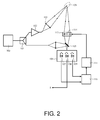
- a central detector 108 and two lateral detectors 107 and 109 located on the right side of the optical reception head are placed in the optical plane of the reception optical head. other of the central detector.
- the central detector 108 delivers the measurement signal S and the two lateral detectors 107 and 109 are used to the enslavement.
- the side detectors thus pick up a backscattered signal in a direction slightly different from the measurement direction. If these lateral signals are of the same intensity and this intensity is lower than that delivered by the central detector, it can be considered that the measurement direction corresponds to the optimal direction. If this is not the case, then the amplitude difference between the lateral signals is representative of the angular difference existing between the measurement direction and the optimal direction.
- This difference can be easily measured by the comparator 110, then integrated by the integrator 111 in order to generate a continuous command applied to the control device 112 of the opto-mechanical displacement means making it possible to move the optical axis of the telescope 104.
- the control device 112 of the opto-mechanical displacement means making it possible to move the optical axis of the telescope 104.
- the telescope 104 may be mounted on a mechanical angular positioning device moving the entire telescope. It is also possible to move one of the optical elements of the optical head or to add in front of the telescope a rotating mobile element such as a diasporameter.
- the system represented in figure 2 allows to enslave the measurement direction in a given plane, in this case the plane of the sheet.
- a servocontrol in a single axis is only necessary in the direction orthogonal to the plane of the two telescopes of emission and reception, taking into account the characteristics of these.
- the same principle can be applied simultaneously in a direction parallel to the plane of the sheet.
- the measuring means comprise two second lateral detectors situated on either side of the central detector, the four detectors being arranged in a rhombus, the measuring means comprising means making it possible to determine, from the knowledge signals from the four lateral detectors, the deviations in two perpendicular planes between the measurement direction of the moving optical axis and the optimal direction.
- This implementation does not present any particular difficulties. Still remaining within the scope of this invention, other combinations of detectors can be envisaged.
- the probe also comprises means for positioning the optical axis of the second optical head so that it crosses the optical axis of the first optical head in the optimum direction. If the optical axis is oscillated around this optimal direction, the intensity of the signal varies symmetrically around this maximum. If the amplitude of the signal varies asymmetrically around a maximum, it means that the mean direction of the oscillation no longer corresponds to the optimal direction. In this case, the amplitude difference corresponding to the extreme positions of the oscillation is significant of the correction to be made. Oscillations can be easily controlled so that the intensity of the backscattered signal varies symmetrically around a maximum. We are sure that the oscillation is around the optimal direction.
Landscapes
- Physics & Mathematics (AREA)
- Engineering & Computer Science (AREA)
- General Physics & Mathematics (AREA)
- Electromagnetism (AREA)
- Radar, Positioning & Navigation (AREA)
- Remote Sensing (AREA)
- Computer Networks & Wireless Communication (AREA)
- Multimedia (AREA)
- Aviation & Aerospace Engineering (AREA)
- Length Measuring Devices By Optical Means (AREA)
- Investigating Or Analysing Materials By Optical Means (AREA)
- Optical Radar Systems And Details Thereof (AREA)
Applications Claiming Priority (1)
| Application Number | Priority Date | Filing Date | Title |
|---|---|---|---|
| FR0906001A FR2953933B1 (fr) | 2009-12-11 | 2009-12-11 | Sonde anemometrique bi-statique asservie |
Publications (1)
| Publication Number | Publication Date |
|---|---|
| EP2333564A1 true EP2333564A1 (de) | 2011-06-15 |
Family
ID=42224698
Family Applications (1)
| Application Number | Title | Priority Date | Filing Date |
|---|---|---|---|
| EP10194184A Withdrawn EP2333564A1 (de) | 2009-12-11 | 2010-12-08 | Servogesteuertes bistatisches Staurohr |
Country Status (4)
| Country | Link |
|---|---|
| US (1) | US20110141470A1 (de) |
| EP (1) | EP2333564A1 (de) |
| CA (1) | CA2724926A1 (de) |
| FR (1) | FR2953933B1 (de) |
Cited By (1)
| Publication number | Priority date | Publication date | Assignee | Title |
|---|---|---|---|---|
| FR3040848A1 (fr) * | 2015-09-08 | 2017-03-10 | Sagem Defense Securite | Procede et systeme d'imagerie bistatique |
Families Citing this family (2)
| Publication number | Priority date | Publication date | Assignee | Title |
|---|---|---|---|---|
| FR2978829B1 (fr) * | 2011-08-04 | 2014-03-21 | Aer | Velocimetre insensible aux conditions givrantes et aux fortes pluies |
| KR102090620B1 (ko) * | 2018-11-27 | 2020-03-18 | 성균관대학교 산학협력단 | 무선 전력 이종통신망에서 후방산란 기반 협력통신 시스템 및 그 방법 |
Citations (3)
| Publication number | Priority date | Publication date | Assignee | Title |
|---|---|---|---|---|
| JP2004309367A (ja) * | 2003-04-09 | 2004-11-04 | Mitsubishi Electric Corp | レーザレーダ装置およびそのビーム方向設定方法 |
| EP1553427A1 (de) * | 2004-01-12 | 2005-07-13 | EADS Astrium GmbH | Ausrichtungs- Steuergerät und bistatisches LIDAR- System |
| US20060227317A1 (en) * | 2005-04-06 | 2006-10-12 | Henderson Sammy W | Efficient lidar with flexible target interrogation pattern |
Family Cites Families (6)
| Publication number | Priority date | Publication date | Assignee | Title |
|---|---|---|---|---|
| US6681054B1 (en) * | 2000-05-01 | 2004-01-20 | Eastman Kodak Company | Noise reduction method utilizing probabilistic weighting, apparatus, and program for digital image processing |
| US6850857B2 (en) * | 2001-07-13 | 2005-02-01 | Honeywell International Inc. | Data fusion of stationary array sensor and scanning sensor measurements |
| US7092579B2 (en) * | 2002-05-20 | 2006-08-15 | Eastman Kodak Company | Calculating noise estimates of a digital image using gradient analysis |
| US7680314B2 (en) * | 2005-10-17 | 2010-03-16 | Siemens Medical Solutions Usa, Inc. | Devices, systems, and methods for improving image consistency |
| US20080118136A1 (en) * | 2006-11-20 | 2008-05-22 | The General Hospital Corporation | Propagating Shell for Segmenting Objects with Fuzzy Boundaries, Automatic Volume Determination and Tumor Detection Using Computer Tomography |
| FR2939202B1 (fr) * | 2008-12-02 | 2011-01-21 | Thales Sa | Sonde d'anemometrie laser bi-axe |
-
2009
- 2009-12-11 FR FR0906001A patent/FR2953933B1/fr not_active Expired - Fee Related
-
2010
- 2010-12-08 EP EP10194184A patent/EP2333564A1/de not_active Withdrawn
- 2010-12-09 US US12/964,393 patent/US20110141470A1/en not_active Abandoned
- 2010-12-10 CA CA2724926A patent/CA2724926A1/en not_active Abandoned
Patent Citations (3)
| Publication number | Priority date | Publication date | Assignee | Title |
|---|---|---|---|---|
| JP2004309367A (ja) * | 2003-04-09 | 2004-11-04 | Mitsubishi Electric Corp | レーザレーダ装置およびそのビーム方向設定方法 |
| EP1553427A1 (de) * | 2004-01-12 | 2005-07-13 | EADS Astrium GmbH | Ausrichtungs- Steuergerät und bistatisches LIDAR- System |
| US20060227317A1 (en) * | 2005-04-06 | 2006-10-12 | Henderson Sammy W | Efficient lidar with flexible target interrogation pattern |
Cited By (1)
| Publication number | Priority date | Publication date | Assignee | Title |
|---|---|---|---|---|
| FR3040848A1 (fr) * | 2015-09-08 | 2017-03-10 | Sagem Defense Securite | Procede et systeme d'imagerie bistatique |
Also Published As
| Publication number | Publication date |
|---|---|
| CA2724926A1 (en) | 2011-06-11 |
| US20110141470A1 (en) | 2011-06-16 |
| FR2953933A1 (fr) | 2011-06-17 |
| FR2953933B1 (fr) | 2012-04-27 |
Similar Documents
| Publication | Publication Date | Title |
|---|---|---|
| EP2339356B1 (de) | Optisches Staurohr mit zwei Messachsen | |
| EP2439541B1 (de) | System zur Bestimmung der Luftgeschwindigkeit eines Flugzeugs | |
| US20130162974A1 (en) | Optical Air Data System Suite of Sensors | |
| FR2869114A1 (fr) | Altimetre laser et appareil de mesure de vitesse au sol combines. | |
| EP3026455B1 (de) | Gepulstes lidar mit halbleiterlaserverstärker | |
| EP1346237B1 (de) | Laser-anemometer | |
| FR2951275A1 (fr) | Dispositif de mesure de la vitesse du vent | |
| CA2870557A1 (fr) | Dispositif de determination de la vitesse du vent comportant une pluralite de sources laser | |
| CN110308454A (zh) | 一种准无盲区多普勒相干激光雷达风速测量系统及方法 | |
| CA2045244A1 (fr) | Dispositif de mesure de parametres meteorologiques | |
| EP0406061B1 (de) | Mit einer bewegbaren Vorrichtung verbundener Apparat zur Erfassung von Signalen, die der Geschwindigkeit dieser Vorrichtung in einem Fluidum entsprechen sowie Messgerät mit einer solchen Vorrichtung | |
| WO1999040398A1 (en) | Improvements in or relating to sound detection | |
| FR2922314A1 (fr) | Dispositif optique de mesure de parametres anemometriques | |
| EP0846274B1 (de) | Optischer geschwindigkeitssensor | |
| EP2333564A1 (de) | Servogesteuertes bistatisches Staurohr | |
| FR2686312A1 (fr) | Vehicule spatial d'observation laser, notamment pour vitesse de vents, et instrument d'observation adapte a en faire partie. | |
| EP2196809B1 (de) | Zweiachsige Laser-Windmessersonde | |
| FR2938922A1 (fr) | Procede et dispositif d'optimisation de l'orientation d'un anemometre laser sur un aeronef. | |
| FR3093567A1 (fr) | Système de mesure anémométrique aéronautique comprenant un lidar à faible puissance | |
| FR3076611A1 (fr) | Dispositif de mesure pour surveiller le niveau de remplissage et effectuer les mesures différentielles de l’indice de réfraction optique | |
| FR2761162A1 (fr) | Dispositif de mesure de vitesse a effet doppler, notamment pour engins volants | |
| FR2971343A1 (fr) | Dispositif aeroporte de telemetrie par laser, a division d'impulsions, et systeme de releve topographique correspondant | |
| CA2680015A1 (fr) | Systeme de metrologie optique | |
| FR2545613A1 (fr) | Appareil de mesure de la vitesse d'un objet, notamment d'un aeronef | |
| EP0911645B1 (de) | Optisches Messgerät zur Feststellung der Entfernung zu einem Objekt und/oder der Geschwindigkeit eines Objekts unter Verwendung von modulierter Polarisations |
Legal Events
| Date | Code | Title | Description |
|---|---|---|---|
| PUAI | Public reference made under article 153(3) epc to a published international application that has entered the european phase |
Free format text: ORIGINAL CODE: 0009012 |
|
| AK | Designated contracting states |
Kind code of ref document: A1 Designated state(s): AL AT BE BG CH CY CZ DE DK EE ES FI FR GB GR HR HU IE IS IT LI LT LU LV MC MK MT NL NO PL PT RO RS SE SI SK SM TR |
|
| AX | Request for extension of the european patent |
Extension state: BA ME |
|
| 17P | Request for examination filed |
Effective date: 20111201 |
|
| 17Q | First examination report despatched |
Effective date: 20130814 |
|
| STAA | Information on the status of an ep patent application or granted ep patent |
Free format text: STATUS: THE APPLICATION IS DEEMED TO BE WITHDRAWN |
|
| 18D | Application deemed to be withdrawn |
Effective date: 20140103 |