EP2333510A1 - Method of wind tunnel measurement of airfoil - Google Patents
Method of wind tunnel measurement of airfoil Download PDFInfo
- Publication number
- EP2333510A1 EP2333510A1 EP10194358A EP10194358A EP2333510A1 EP 2333510 A1 EP2333510 A1 EP 2333510A1 EP 10194358 A EP10194358 A EP 10194358A EP 10194358 A EP10194358 A EP 10194358A EP 2333510 A1 EP2333510 A1 EP 2333510A1
- Authority
- EP
- European Patent Office
- Prior art keywords
- airfoil
- wind tunnel
- thin film
- film member
- model
- Prior art date
- Legal status (The legal status is an assumption and is not a legal conclusion. Google has not performed a legal analysis and makes no representation as to the accuracy of the status listed.)
- Granted
Links
- 238000005259 measurement Methods 0.000 title claims abstract description 33
- 238000000034 method Methods 0.000 title claims abstract description 25
- 239000010409 thin film Substances 0.000 claims abstract description 56
- 239000012530 fluid Substances 0.000 claims abstract description 25
- 239000000463 material Substances 0.000 claims abstract description 6
- 230000008878 coupling Effects 0.000 claims abstract description 4
- 238000010168 coupling process Methods 0.000 claims abstract description 4
- 238000005859 coupling reaction Methods 0.000 claims abstract description 4
- 239000011347 resin Substances 0.000 claims description 3
- 229920005989 resin Polymers 0.000 claims description 3
- 238000006073 displacement reaction Methods 0.000 description 3
- 230000007246 mechanism Effects 0.000 description 3
- 239000013013 elastic material Substances 0.000 description 2
- 230000000903 blocking effect Effects 0.000 description 1
- 230000008859 change Effects 0.000 description 1
- 239000010408 film Substances 0.000 description 1
- 238000000691 measurement method Methods 0.000 description 1
- 239000004033 plastic Substances 0.000 description 1
- 229920003023 plastic Polymers 0.000 description 1
- 238000011084 recovery Methods 0.000 description 1
- 230000009467 reduction Effects 0.000 description 1
- 229920002379 silicone rubber Polymers 0.000 description 1
Images


Classifications
-
- G—PHYSICS
- G01—MEASURING; TESTING
- G01M—TESTING STATIC OR DYNAMIC BALANCE OF MACHINES OR STRUCTURES; TESTING OF STRUCTURES OR APPARATUS, NOT OTHERWISE PROVIDED FOR
- G01M9/00—Aerodynamic testing; Arrangements in or on wind tunnels
- G01M9/02—Wind tunnels
- G01M9/04—Details
-
- G—PHYSICS
- G01—MEASURING; TESTING
- G01M—TESTING STATIC OR DYNAMIC BALANCE OF MACHINES OR STRUCTURES; TESTING OF STRUCTURES OR APPARATUS, NOT OTHERWISE PROVIDED FOR
- G01M9/00—Aerodynamic testing; Arrangements in or on wind tunnels
- G01M9/06—Measuring arrangements specially adapted for aerodynamic testing
- G01M9/062—Wind tunnel balances; Holding devices combined with measuring arrangements
Definitions
- the present invention relates to a method of wind tunnel measurement of airfoil, and more particularly relates to a method of wind tunnel measurement of airfoil, which is used for in a windmill, an aircraft, a turbine and the like.
- the blade of the windmill, the aircraft or the like is high in aspect ratio (fineness ratio) (e.g., 10 to 20 or more) .
- aspect ratio fineness ratio
- the aerodynamic design and the calculation of the aerodynamic performance of the entire blade are carried out by determining the aerodynamic performance of a two-dimensional airfoil section and integrating it in a blade width direction and then estimating a three-dimensional performance. In that case, it is necessary to carry out a wind tunnel test under a condition close to an actual use condition to get the aerodynamic characteristics of the two-dimensional airfoil section.
- the flow of the fluid in the actual entire blade is three-dimensional.
- the aspect ratio of the actual blade is high.
- the flow of the fluid can be considered to be two-dimensional except the blade ends.
- Japanese Patent Publication No. JP-A-Heisei 9-210839 discloses a wind tunnel test apparatus for a structure.
- This wind tunnel test apparatus for a structure includes: a wind guiding path through which air flows; a model which is arranged in the wind guiding path and has an axis serving as a rotation center; a suspending wire suspending and holding the model in the wind guiding path; a detector which detects various forces generated in the model through the suspending wire when the model receives the flow of air; a model rotating mechanism which has a motor and a decelerator interlocking with the motor and rotates the model around the axis to change an orientation of the model with respect to a direction of the flow of air; and an actuator which is remotely operated.
- This wind tunnel test apparatus is characterized by containing a fixing mechanism for fixing the model in an orientation determined by the model rotating mechanism.
- Fig. 1 is a schematic view showing the method of the wind tunnel test studied by the inventors.
- a wind tunnel test apparatus 101 includes two walls 102, two supporting members 104 and two load cells 103.
- Each of the two walls 102 has a flat surface parallel to an x-direction.
- the two walls 102 are arranged at a predetermined distance from each other in a z-direction.
- the space between the walls 102 configures a wind tunnel flow path.
- An airfoil (airfoil model 111) under test is arranged in the wind tunnel flow path.
- a fluid (air) for the wind tunnel test flows through the wind tunnel flow path.
- the upper supporting member 104 is arranged to penetrate through the upper wall 102 in the z-direction and not to interfere with the upper wall 102.
- the lower supporting member 104 is arranged to penetrate through the lower wall 102 in the z-direction and not to interfere with the lower wall 102.
- one end is coupled with the top end of the airfoil model 111, and the other end is coupled with the upper load cell 103.
- the lower supporter 104 one end is coupled with the bottom end of the airfoil model 111, and the other end is coupled with the lower load cell 103.
- the two load cells 103 fix the airfoil model 111 in the z-direction through the supporting members 104, respectively.
- the load cells 103 measure loads in the x-direction and the y-direction that are applied to the airfoil model 111 at the time of the wind tunnel test.
- the airfoil model 111 has the shape in which the airfoil is cut away in the two flat surfaces vertical to the longitudinal direction of the airfoil.
- the two supporting members 104 are connected to both ends of the airfoil model 111 that correspond to the two cutaway surfaces, respectively.
- the airfoil model 111 when the airfoil model 111 is placed inside the wind tunnel flow path and then the load is measured by using the load cells 103, a pair of balances or the like, it is considered that the following case occurs. That is, the airfoil model 111 is moved in the z-direction, then the airfoil model 111 is brought into contact with the surface of the wall 102, and consequently the load in the airfoil model 111 cannot be properly measured. Thus, in order to avoid the influence on the z-direction displacement of the airfoil model 111, it is required to form a gap between the airfoil model 111 and each of the two walls 102. Fig.
- FIG. 2 is a schematic view showing a relation between the airfoil model 111 and the wall 102. As shown in Fig. 2 , a gap with an interval d1 is formed between the airfoil model 111 and the wall 102. For example, in the case of the airfoil model III having an airfoil chord length of 1500 mm, the interval d1 is approximately 10 mm.
- the gap flow 110 is the flow that the fluid moves from the side of a positive pressure surface to the side of a negative pressure surface in the airfoil model 111.
- the flow of the fluid is not two-dimensional originally scheduled but three-dimensional. This results in the loss of the lifting power of the airfoil model 111.
- an object of the present invention is to provide a method of wind tunnel measurement of airfoil, which can measure aerodynamic characteristics of a two-dimensional airfoil section more accurately. Also, another object of the present invention is to provide a method of wind tunnel measurement of airfoil, which can make the flow of the fluid more two-dimensional.
- the present invention provides a method of wind tunnel measurement of airfoil, including: providing a wind tunnel test apparatus, the wind tunnel test apparatus including: two walls configuring a wind tunnel flow path therebetween, two supporting members arranged to penetrate through the two walls, respectively, and not to interfere with the two walls, and two load measuring units holding the two supporting members, respectively; coupling both ends of a airfoil model under test with the two supporting members, respectively; generating a flow of a fluid in the wind tunnel flow path; and measuring a load applied to the airfoil model by using the two load measuring units.
- a thin film member is stuck on each end of the airfoil model so that a part of the thin film member protrudes from the each end of the airfoil model along an outer circumference throughout an entire circumference.
- the thin film member has a strength at which the thin film member enables to endure a pressure of the fluid, and is formed of a material which is elastically deformable.
- the thin film member is provided so that a gap between the each end of the airfoil model and one of the two walls facing to the each end of the airfoil model is blocked.
- the present invention it is possible to provide a method of wind tunnel measurement of airfoil, which can measure aerodynamic characteristics of a two-dimensional airfoil section more accurately. Also, according to the present invention, it is possible to provide a method of wind tunnel measurement of airfoil, which can make the flow of the fluid more two-dimensional.
- Fig. 3 is a schematic view showing an airfoil wind tunnel measurement apparatus according to the embodiment of the present invention.
- a wind tunnel test apparatus 1 includes two walls 2, two supporting members 4 and two load cells 3.
- Each of the two walls 2 has a flat surface parallel to an x-direction.
- the two walls 2 are arranged at a predetermined distance from each other in a z-direction.
- the space between the walls 2 configures a wind tunnel flow path 6.
- An airfoil (airfoil model 11) under test is arranged in the wind tunnel flow path 6.
- a fluid (air) for the wind tunnel test flows through the wind tunnel flow path 6.
- the upper supporting member 4 is arranged to penetrate through the upper wall 2 in the z-direction and not to interfere with the upper wall 2.
- the lower supporting member 4 is arranged to penetrate through the lower wall 2 in the z-direction and not to interfere with the lower wall 2.
- one end is coupled with the top end of the airfoil model 11, and the other end is coupled with the upper load cell 3.
- the lower supporting member 4 one end is coupled with the bottom end of the airfoil model 11, and the other end is coupled with the lower load cell 3.
- the two load cells 3 fix the airfoil model 11 in the z-direction through the supporting members 4 , respectively.
- the load cells 3 measure loads in the x-direction and the y-direction that are applied to the airfoil model 11 at the time of the wind tunnel test. However, a different device may be used if the loads in the x-direction and the y-direction can be measured.
- the airfoil model 11 has the shape in which the airfoil is cut away in two flat surfaces vertical to the longitudinal direction of the airfoil, or has the shape similar thereto.
- the two supporting members 4 are connected to both ends of the airfoil model 11 that correspond to the two cutaway surfaces, respectively.
- Fig. 4 is a schematic view showing a relation between the airfoil model 11 and the wall 2.
- the airfoil model 11 is placed inside the wind tunnel flow path 6 and then the load is measured by using the load cells 3, the pair of balances or the like, it is considered that the following case occurs. That is, the airfoil model 11 is moved in the z-direction, then the balance model 11 is brought into contact with the surface of the wall 2, and consequently the load in the airfoil model 11 cannot be properly measured.
- a gap with an interval d1 is formed between the airfoil model 11 and the wall 2.
- the interval d1 is approximately 10 mm.
- a thin film member 5 is arranged so that the gap between the airfoil model 11 and the wall 2 is blocked to avoid the above gap flow (the gap flow 110 in Fig. 2 ).
- a distance d2 between the wall 2 and the lower end of the thin film member 5 is as small as possible. It is further preferred that the distance d2 is substantially zero.
- Fig. 5 is a schematic view showing a relation between the airfoil model 11 and the thin film member 5.
- the thin film member 5 is the member having the shape of a thin film.
- the thin film member 5 is attached along an outer circumference of the end of the airfoil model 11 so that a part of the thin film member 5 protrudes from the end of the airfoil model 11 in the z-direction throughout the entire circumference (a circuit of the circumference) .
- the thin film member 5 has a function for preventing: the generation of the gap flow (the gap flow 110 in Fig.
- the width that protrudes in the z-direction from the end of the airfoil model 11 is preferred to be the same width throughout the circumference. Consequently, the function for preventing the generation of the above gap flow and the like can be exerted more surely.
- the thin film member 5 has a strength at which the thin film member 5 can endure the pressure (wind pressure) of the fluid (air) for the wind tunnel test. That is, it is not substantially deformed under that pressure of the fluid. Also, the thin film member 5 does not limit the motion of the airfoil model 11 even if the thin film member 5 is brought into contact with one of the two walls. That is, since the thin film member 5 can be deformed when the thin film member 5 is brought into contact with the wall 2, the load applied to the airfoil model 11 is not substantially generated. Also, the thin film member 5 can be deformed along the outer circumference of the airfoil model 11. That is, it can be stuck (adhere) along the outer circumference.
- an elastic material is preferable.
- an elastically deformable resin is exemplified.
- a tape made of the elastically deformable resin is further preferable.
- a protecting tape that has a width of 15 mm and a thickness of 0.5 mm and pertains to a silicon rubber film "KEIJU" made by MITSUBISHI PLASTICS, Inc.
- Such a material is preferable because there is a merit that the size is easily adjusted based on the dimension of the interval d1, it is easy to attach and detach the material to the airfoil model 11, and the airfoil model 11 is not damaged.
- the quantity (area) of the thin film member 5 is very small as compared with that of the airfoil model 11. Thus, its elastic force does not have influence on the load of the airfoil model 11.
- the thin film member 5 is arranged on the side of the airfoil model 11 and not on the side of the wall 2. This reason is as follows. That is, when the thin film member 5 is arranged on the side of the wall 2 and when the airfoil model 11 is moved, the gap is formed between the thin film member 5 fixed to the wall 2 and the end of the airfoil model 11. Thus, it is impossible to prevent: the generation of the gap flow in which the fluid moves from the side of the positive pressure surface to the side of the negative pressure surface in the airfoil model 11; and the increase in the blade tip vortex.
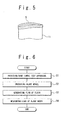
- Fig. 6 is a flowchart showing the airfoil wind tunnel measurement method according to the embodiment of the present invention.
- the wind tunnel test apparatus 1 is prepared as shown in Fig. 3 (Step S1) . That is, the wind tunnel test apparatus 1 is prepared which includes: the two walls 2 configuring the wind tunnel flow path 6; the two supporting members 4 arranged to penetrate through the two walls 2, respectively, and not to interfere with the two walls 2; and the two load cells 3 holding the two supporting members 4, respectively.
- both ends of the airfoil model 11 under test are fixed (connected) to the two supporting members 4, respectively.
- the thin film members 5 are stuck (attached) onto both ends of the airfoil model 11 fixed to the support members 4 (Step S2). That is, one of the two supporting members 4 is coupled with one end of the airfoil model 11, and the other of the two supporting members 4 is coupled with the other end of the airfoil model 11.
- the thin film member 5 is stuck (adheres) so that a part of the thin film member 5 protrudes from the end of the airfoil model 11 along the outer circumference throughout the entire circumference.
- the thin film member 5 is stuck (adheres) onto the airfoil model 11 so that both of the distance between the upper wall 2 and the upper thin film member 5 and the distance between the lower wall 2 and the lower thin film member 5 become substantially zero. Since such an order is set, the sticking of the thin film member 5 can be easily adjusted, on the basis of the gap between the airfoil model 11 and the wall 2.
- the operation of sticking the thin film member 5 onto both the ends of the airfoil model 11 may be carried out before the airfoil model 11 is attached to the supporting members 4.
- the distance can be adjusted by using a method of, for example, re-sticking the thin film member 5, or cutting away the thin film member 5, or the like.
- Fig. 7 is a schematic view showing a relation between the fluid of the speed U and the airfoil model 11.
- the lift L ( ⁇ ) is the airfoil load to be measured
- the air density p is known
- the air speed U is the set value (measurement condition)
- the airfoil chord length C is known
- the angle of attack ⁇ is the set value (measurement condition).
- Fig. 8 is a graph showing one example of the relation between the angle of attack ⁇ and the lift coefficient C 1 ( ⁇ ) determined by the measurement.
- the lateral axis indicates the angle of attack ⁇
- the longitudinal axis indicates the lift coefficient C 1 ( ⁇ ).
- the curve "A” indicates the case that the airfoil wind tunnel measurement is carried out while the airfoil wind tunnel measurement apparatus and the airfoil model shown in Figs. 3 to 5 are used.
- a curve "B" indicates the case that the airfoil wind tunnel measurement is carried out while the airfoil wind tunnel measurement apparatus and the airfoil model shown in Fig. 1 are used.
- the method of the airfoil wind tunnel measurement in this embodiment can extremely reduce (suppress): the generation of the gap flow in which the fluid moves from the side of the positive pressure surface to the side of the negative pressure surface in the airfoil model 11; and the increase in the airfoil tip vortex, because the gap d1 between the airfoil model 11 and the wall 2 is blocked with the thin film member 5.
- the flow of the fluid can be surely made two-dimensional .
- the method of the airfoil wind tunnel measurement in this embodiment enables the wind tunnel measurement that is intended to obtain the aerodynamic characteristics of the blade under the condition close to the actual use.
Abstract
Description
- The present invention relates to a method of wind tunnel measurement of airfoil, and more particularly relates to a method of wind tunnel measurement of airfoil, which is used for in a windmill, an aircraft, a turbine and the like.
- As an apparatus that uses a blade, a windmill, an aircraft, a turbine and the like are known. The blade of the windmill, the aircraft or the like is high in aspect ratio (fineness ratio) (e.g., 10 to 20 or more) . For this reason, in many cases, the aerodynamic design and the calculation of the aerodynamic performance of the entire blade are carried out by determining the aerodynamic performance of a two-dimensional airfoil section and integrating it in a blade width direction and then estimating a three-dimensional performance. In that case, it is necessary to carry out a wind tunnel test under a condition close to an actual use condition to get the aerodynamic characteristics of the two-dimensional airfoil section.
- One of the conditions for the wind tunnel test is to secure the two-dimensional flow property. The flow of the fluid in the actual entire blade is three-dimensional. However, as mentioned above, the aspect ratio of the actual blade is high. Thus, from the viewpoint of each blade element, the flow of the fluid can be considered to be two-dimensional except the blade ends. Hence, in the wind tunnel test, it is important to remove the three-dimensional flow property of the fluid and secure its two-dimensional flow property.
- As a related technique, Japanese Patent Publication No.
JP-A-Heisei 9-210839 - The inventors have now discovered the following facts.
- The inventors have studied the following method as a method of a wind tunnel test.
Fig. 1 is a schematic view showing the method of the wind tunnel test studied by the inventors. As shown inFig. 1 , a windtunnel test apparatus 101 includes twowalls 102, two supportingmembers 104 and twoload cells 103. Each of the twowalls 102 has a flat surface parallel to an x-direction. The twowalls 102 are arranged at a predetermined distance from each other in a z-direction. The space between thewalls 102 configures a wind tunnel flow path. An airfoil (airfoil model 111) under test is arranged in the wind tunnel flow path. A fluid (air) for the wind tunnel test flows through the wind tunnel flow path. The upper supportingmember 104 is arranged to penetrate through theupper wall 102 in the z-direction and not to interfere with theupper wall 102. The lower supportingmember 104 is arranged to penetrate through thelower wall 102 in the z-direction and not to interfere with thelower wall 102. In the upper supportingmember 104, one end is coupled with the top end of theairfoil model 111, and the other end is coupled with theupper load cell 103. In thelower supporter 104, one end is coupled with the bottom end of theairfoil model 111, and the other end is coupled with thelower load cell 103. The twoload cells 103 fix theairfoil model 111 in the z-direction through the supportingmembers 104, respectively. Theload cells 103 measure loads in the x-direction and the y-direction that are applied to theairfoil model 111 at the time of the wind tunnel test. Theairfoil model 111 has the shape in which the airfoil is cut away in the two flat surfaces vertical to the longitudinal direction of the airfoil. The two supportingmembers 104 are connected to both ends of theairfoil model 111 that correspond to the two cutaway surfaces, respectively. - In this way, when the
airfoil model 111 is placed inside the wind tunnel flow path and then the load is measured by using theload cells 103, a pair of balances or the like, it is considered that the following case occurs. That is, theairfoil model 111 is moved in the z-direction, then theairfoil model 111 is brought into contact with the surface of thewall 102, and consequently the load in theairfoil model 111 cannot be properly measured. Thus, in order to avoid the influence on the z-direction displacement of theairfoil model 111, it is required to form a gap between theairfoil model 111 and each of the twowalls 102.Fig. 2 is a schematic view showing a relation between theairfoil model 111 and thewall 102. As shown inFig. 2 , a gap with an interval d1 is formed between theairfoil model 111 and thewall 102. For example, in the case of the airfoil model III having an airfoil chord length of 1500 mm, the interval d1 is approximately 10 mm. - However, with the existence of this gap, there is a possibility that a
gap flow 110 occurs and/or an airfoil tip vortex (not shown) increases. Here, thegap flow 110 is the flow that the fluid moves from the side of a positive pressure surface to the side of a negative pressure surface in theairfoil model 111. In that case, the flow of the fluid is not two-dimensional originally scheduled but three-dimensional. This results in the loss of the lifting power of theairfoil model 111. Thus, it is difficult to obtain the aerodynamic characteristics of the two-dimensional airfoil section that is originally purposed. - Therefore, an object of the present invention is to provide a method of wind tunnel measurement of airfoil, which can measure aerodynamic characteristics of a two-dimensional airfoil section more accurately. Also, another object of the present invention is to provide a method of wind tunnel measurement of airfoil, which can make the flow of the fluid more two-dimensional.
- In order to achieve an aspect of the present invention, the present invention provides a method of wind tunnel measurement of airfoil, including: providing a wind tunnel test apparatus, the wind tunnel test apparatus including: two walls configuring a wind tunnel flow path therebetween, two supporting members arranged to penetrate through the two walls, respectively, and not to interfere with the two walls, and two load measuring units holding the two supporting members, respectively; coupling both ends of a airfoil model under test with the two supporting members, respectively; generating a flow of a fluid in the wind tunnel flow path; and measuring a load applied to the airfoil model by using the two load measuring units. A thin film member is stuck on each end of the airfoil model so that a part of the thin film member protrudes from the each end of the airfoil model along an outer circumference throughout an entire circumference. The thin film member has a strength at which the thin film member enables to endure a pressure of the fluid, and is formed of a material which is elastically deformable. The thin film member is provided so that a gap between the each end of the airfoil model and one of the two walls facing to the each end of the airfoil model is blocked.
- According to the present invention, it is possible to provide a method of wind tunnel measurement of airfoil, which can measure aerodynamic characteristics of a two-dimensional airfoil section more accurately. Also, according to the present invention, it is possible to provide a method of wind tunnel measurement of airfoil, which can make the flow of the fluid more two-dimensional.
- The above and other objects, advantages and features of the present invention will be more apparent from the following description of certain preferred embodiments taken in conjunction with the accompanying drawings, in which:
-
Fig. 1 is a schematic view showing a wind tunnel test apparatus studied by the inventor; -
Fig. 2 is a schematic view showing a relation between an airfoil model and a wall; -
Fig. 3 is a schematic view showing a method of wind tunnel measurement of airfoil according to an embodiment of the present invention; -
Fig. 4 is a schematic view showing a relation between an airfoil model and a wall; -
Fig. 5 is a schematic view showing a relation between an airfoil model and a thin film member; -
Fig. 6 is a flowchart showing a method of wind tunnel measurement of airfoil according to the embodiment of the present invention; -
Fig. 7 is a schematic view showing a relation between a fluid and an airfoil model; and -
Fig. 8 is a graph showing one example of a relation between an angle of attack and a lift coefficient determined by a measurement. - An embodiment of a method of wind tunnel measurement of airfoil according to the present invention will be described below with reference to the attached drawings.
- At first, an airfoil wind tunnel measurement apparatus according to the embodiment of the present invention will be described.
Fig. 3 is a schematic view showing an airfoil wind tunnel measurement apparatus according to the embodiment of the present invention. As shown inFig. 3 , a wind tunnel test apparatus 1 includes twowalls 2, two supportingmembers 4 and twoload cells 3. Each of the twowalls 2 has a flat surface parallel to an x-direction. The twowalls 2 are arranged at a predetermined distance from each other in a z-direction. The space between thewalls 2 configures a windtunnel flow path 6. An airfoil (airfoil model 11) under test is arranged in the windtunnel flow path 6. A fluid (air) for the wind tunnel test flows through the windtunnel flow path 6. The upper supportingmember 4 is arranged to penetrate through theupper wall 2 in the z-direction and not to interfere with theupper wall 2. The lower supportingmember 4 is arranged to penetrate through thelower wall 2 in the z-direction and not to interfere with thelower wall 2. In the upper supportingmember 4, one end is coupled with the top end of theairfoil model 11, and the other end is coupled with theupper load cell 3. In the lower supportingmember 4, one end is coupled with the bottom end of theairfoil model 11, and the other end is coupled with thelower load cell 3. The twoload cells 3 fix theairfoil model 11 in the z-direction through the supportingmembers 4 , respectively. Theload cells 3 measure loads in the x-direction and the y-direction that are applied to theairfoil model 11 at the time of the wind tunnel test. However, a different device may be used if the loads in the x-direction and the y-direction can be measured. Theairfoil model 11 has the shape in which the airfoil is cut away in two flat surfaces vertical to the longitudinal direction of the airfoil, or has the shape similar thereto. The two supportingmembers 4 are connected to both ends of theairfoil model 11 that correspond to the two cutaway surfaces, respectively. -
Fig. 4 is a schematic view showing a relation between theairfoil model 11 and thewall 2. As mentioned above, when theairfoil model 11 is placed inside the windtunnel flow path 6 and then the load is measured by using theload cells 3, the pair of balances or the like, it is considered that the following case occurs. That is, theairfoil model 11 is moved in the z-direction, then thebalance model 11 is brought into contact with the surface of thewall 2, and consequently the load in theairfoil model 11 cannot be properly measured. Thus, in order to avoid the influence on the z-direction displacement of theairfoil model 11, as shown inFig. 4 , a gap with an interval d1 is formed between theairfoil model 11 and thewall 2. For example, in the case of theairfoil model 11 having an airfoil chord length of 1500 mm, the interval d1 is approximately 10 mm. At this time, on each of both ends of theairfoil model 11, athin film member 5 is arranged so that the gap between theairfoil model 11 and thewall 2 is blocked to avoid the above gap flow (thegap flow 110 inFig. 2 ). It is preferred that a distance d2 between thewall 2 and the lower end of thethin film member 5 is as small as possible. It is further preferred that the distance d2 is substantially zero. Hence, a function for preventing the above gap flow (thegap flow 110 inFig. 2 ) from being generated and the like can be exerted more surely. -
Fig. 5 is a schematic view showing a relation between theairfoil model 11 and thethin film member 5. Thethin film member 5 is the member having the shape of a thin film. Thethin film member 5 is attached along an outer circumference of the end of theairfoil model 11 so that a part of thethin film member 5 protrudes from the end of theairfoil model 11 in the z-direction throughout the entire circumference (a circuit of the circumference) . Thethin film member 5 has a function for preventing: the generation of the gap flow (thegap flow 110 inFig. 2 ) in which the fluid moves from the side of a positive pressure surface to the side of a negative pressure surface in theairfoil model 11; and the increase in the airfoil tip vortex, at the time of the airfoil wind tunnel measurement. In thethin film member 5 adhering (or stuck) to the end of theairfoil model 11, the width that protrudes in the z-direction from the end of theairfoil model 11 is preferred to be the same width throughout the circumference. Consequently, the function for preventing the generation of the above gap flow and the like can be exerted more surely. - The
thin film member 5 has a strength at which thethin film member 5 can endure the pressure (wind pressure) of the fluid (air) for the wind tunnel test. That is, it is not substantially deformed under that pressure of the fluid. Also, thethin film member 5 does not limit the motion of theairfoil model 11 even if thethin film member 5 is brought into contact with one of the two walls. That is, since thethin film member 5 can be deformed when thethin film member 5 is brought into contact with thewall 2, the load applied to theairfoil model 11 is not substantially generated. Also, thethin film member 5 can be deformed along the outer circumference of theairfoil model 11. That is, it can be stuck (adhere) along the outer circumference. With those facts, even if theairfoil model 11 is moved during the wind tunnel test and thethin film member 5 is brought into contact with thewall 2 by some chance, thethin film member 5 is only deformed, which can extremely reduce the influence on the load that is applied to theairfoil model 11 being currently measured. That is, even if theairfoil model 11 is displaced, the generation of the gap flow and the increase in the airfoil tip vortex can be prevented by surely blocking the gap without any influence on the airfoil load. - As the material of the above
thin film member 5, an elastic material is preferable. As the elastic material, an elastically deformable resin is exemplified. A tape made of the elastically deformable resin is further preferable. As one example of a specific product, there is a protecting tape that has a width of 15 mm and a thickness of 0.5 mm and pertains to a silicon rubber film "KEIJU" made by MITSUBISHI PLASTICS, Inc. Such a material is preferable because there is a merit that the size is easily adjusted based on the dimension of the interval d1, it is easy to attach and detach the material to theairfoil model 11, and theairfoil model 11 is not damaged. Incidentally, the quantity (area) of thethin film member 5 is very small as compared with that of theairfoil model 11. Thus, its elastic force does not have influence on the load of theairfoil model 11. - Also, the
thin film member 5 is arranged on the side of theairfoil model 11 and not on the side of thewall 2. This reason is as follows. That is, when thethin film member 5 is arranged on the side of thewall 2 and when theairfoil model 11 is moved, the gap is formed between thethin film member 5 fixed to thewall 2 and the end of theairfoil model 11. Thus, it is impossible to prevent: the generation of the gap flow in which the fluid moves from the side of the positive pressure surface to the side of the negative pressure surface in theairfoil model 11; and the increase in the blade tip vortex. - The method of the airfoil wind tunnel measurement according to the embodiment of the present invention will be described below with reference to
Figs. 3 to 6 . Here,Fig. 6 is a flowchart showing the airfoil wind tunnel measurement method according to the embodiment of the present invention. At first, the wind tunnel test apparatus 1 is prepared as shown inFig. 3 (Step S1) . That is, the wind tunnel test apparatus 1 is prepared which includes: the twowalls 2 configuring the windtunnel flow path 6; the two supportingmembers 4 arranged to penetrate through the twowalls 2, respectively, and not to interfere with the twowalls 2; and the twoload cells 3 holding the two supportingmembers 4, respectively. - Next, as shown in
Fig. 3 , both ends of theairfoil model 11 under test are fixed (connected) to the two supportingmembers 4, respectively. In succession, as shown inFig. 5 , thethin film members 5 are stuck (attached) onto both ends of theairfoil model 11 fixed to the support members 4 (Step S2). That is, one of the two supportingmembers 4 is coupled with one end of theairfoil model 11, and the other of the two supportingmembers 4 is coupled with the other end of theairfoil model 11. In succession, on each of both ends of theairfoil model 11, thethin film member 5 is stuck (adheres) so that a part of thethin film member 5 protrudes from the end of theairfoil model 11 along the outer circumference throughout the entire circumference. At that time, thethin film member 5 is stuck (adheres) onto theairfoil model 11 so that both of the distance between theupper wall 2 and the upperthin film member 5 and the distance between thelower wall 2 and the lowerthin film member 5 become substantially zero. Since such an order is set, the sticking of thethin film member 5 can be easily adjusted, on the basis of the gap between theairfoil model 11 and thewall 2. Incidentally, the operation of sticking thethin film member 5 onto both the ends of theairfoil model 11 may be carried out before theairfoil model 11 is attached to the supportingmembers 4. In that case, the distance can be adjusted by using a method of, for example, re-sticking thethin film member 5, or cutting away thethin film member 5, or the like. - After that, in the wind
tunnel flow path 6 configured by the twowalls 2, the flow of the fluid is generated at the predetermined angle of attack and speed U (Step S3) . That is, for theairfoil model 11 inside the windtunnel flow path 6, the flow of the air is generated at the predetermined angle of attack and speed U. Then, the load (lift) applied to theairfoil model 11 is measured by using the two load cells 3 (Step S4) .Fig. 7 is a schematic view showing a relation between the fluid of the speed U and theairfoil model 11. When the fluid (air) is supplied to theairfoil model 11 at the angle of attack α and the speed U, the lift L (airfoil load) is calculated by the following equation.
- Here, the lift L (α) is the airfoil load to be measured, the air density p is known, the air speed U is the set value (measurement condition) , the airfoil chord length C is known, and the angle of attack α is the set value (measurement condition). Thus, from the above measurement, it is possible to calculate the lift coefficient C1(α0) with respect to the predetermined angle of attack α0. Then, for the various directions (various angles of attack α), the above steps S3 and S4 are carried out, which can determine the relation between the angles of attack α and the lift coefficients C1(α).
-
Fig. 8 is a graph showing one example of the relation between the angle of attack α and the lift coefficient C1 (α) determined by the measurement. The lateral axis indicates the angle of attack α, and the longitudinal axis indicates the lift coefficient C1(α). In this figure, the curve "A" indicates the case that the airfoil wind tunnel measurement is carried out while the airfoil wind tunnel measurement apparatus and the airfoil model shown inFigs. 3 to 5 are used. A curve "B" indicates the case that the airfoil wind tunnel measurement is carried out while the airfoil wind tunnel measurement apparatus and the airfoil model shown inFig. 1 are used. In the case of the curve "B", the drops in the lift coefficient and the lift slope can be confirmed as compared with the curve "A" . This is considered to result from the fact that the flow around the airfoil is three-dimensional. On the other hand, in the case of the curve "A", the recoveries of the lift coefficient and the lift slope can be confirmed as compared with the curve "B" . That is, the relation between the angle of attack α and the lift coefficient C1(α) is known to be linear. This is considered to result from the fact that the flow around the airfoil is two-dimensional. Thus, it is possible to get the aerodynamic characteristics of the two-dimensional airfoil section, such as the curve "A". - That is, the method of the airfoil wind tunnel measurement in this embodiment can extremely reduce (suppress): the generation of the gap flow in which the fluid moves from the side of the positive pressure surface to the side of the negative pressure surface in the
airfoil model 11; and the increase in the airfoil tip vortex, because the gap d1 between theairfoil model 11 and thewall 2 is blocked with thethin film member 5. Thus, the flow of the fluid can be surely made two-dimensional . As a result, it is possible to properly obtain the aerodynamic characteristics of the two-dimensional airfoil section, which is intended in the airfoil wind tunnel measurement. - Also, even if the
airfoil model 11 is displaced during the wind tunnel test and thethin film member 5 is brought into contact with thewall 2 by some chance, only thethin film member 5 is deformed. This leads to significant reduction of the displacement influence on the load applied to theairfoil model 11 that is being measured. That is, the generation of the gap flow and the increase in the airfoil tip vortex can be prevented without any influence on the airfoil load. - As the foregoing results, the method of the airfoil wind tunnel measurement in this embodiment enables the wind tunnel measurement that is intended to obtain the aerodynamic characteristics of the blade under the condition close to the actual use. Thus, it is possible to improve the aerodynamic design of the blade and the precision of the aerodynamic performance calculation.
- It is apparent that the present invention is not limited to the above embodiment, but may be modified and changed without departing from the scope and spirit of the invention.
- Although the present invention has been described above in connection with several exemplary embodiments thereof, it would be apparent to those skilled in the art that those exemplary embodiments are provided solely for illustrating the present invention, and shouldnot be relied upon to construe the appended claims in a limiting sense.
Claims (4)
- A method of wind tunnel measurement of airfoil, comprising:providing a wind tunnel test apparatus (1), said wind tunnel test apparatus (1) including:two walls (2) configuring a wind tunnel flow path therebetween,two supporting members (4) arranged to penetrate through said two walls (2), respectively, and not to interfere with said two walls (2), andtwo load measuring units (3) holding said two supporting members (4), respectively;coupling both ends of a airfoil model (11) under test with the two supporting members (4), respectively;generating a flow of a fluid in said wind tunnel flow path; andmeasuring a load applied to said airfoil model (11) by using said two load measuring units (3),wherein a thin film member (5) is stuck on each end of said airfoil model (11) so that a part of said thin film member (5) protrudes from said each end of said airfoil model (11) along an outer circumference throughout an entire circumference,wherein said thin film member (5) has a strength at which said thin film member (5) enables to endure a pressure of said fluid, and is formed of a material which is elastically deformable, andwherein said thin film member (5) is provided so that a gap between said each end of said airfoil model (11) and one of said two walls (2) facing to said each end of said airfoil model (11) is blocked.
- The method of an airfoil wind tunnel measurement according to claim 1, further comprising:sticking said thin film member (5) onto said each end of said airfoil model (11) so that said part of said thin film member (5) protrudes from said each end of said airfoil model (11) along said outer circumference throughout said entire circumference.
- The method of an airfoil wind tunnel measurement according to claim 1 or 2, wherein said coupling step includes:adjusting said thin filmmember (5) so that a distance between said thin film member (5) stuck on said each end of said airfoil model (11) and one of said two walls (2) facing said thin f ilmmember (5) becomes substantially zero.
- The method of an airfoil wind tunnel measurement according to any one of claims 1 to 3, wherein said thin film member (5) includes a resin tape.
Applications Claiming Priority (1)
| Application Number | Priority Date | Filing Date | Title |
|---|---|---|---|
| JP2009280679A JP5244773B2 (en) | 2009-12-10 | 2009-12-10 | Wing wind tunnel test method |
Publications (3)
| Publication Number | Publication Date |
|---|---|
| EP2333510A1 true EP2333510A1 (en) | 2011-06-15 |
| EP2333510B1 EP2333510B1 (en) | 2012-10-10 |
| EP2333510B8 EP2333510B8 (en) | 2013-02-13 |
Family
ID=43735170
Family Applications (1)
| Application Number | Title | Priority Date | Filing Date |
|---|---|---|---|
| EP10194358A Not-in-force EP2333510B8 (en) | 2009-12-10 | 2010-12-09 | Method of wind tunnel measurement of airfoil |
Country Status (5)
| Country | Link |
|---|---|
| US (1) | US8359916B2 (en) |
| EP (1) | EP2333510B8 (en) |
| JP (1) | JP5244773B2 (en) |
| DK (1) | DK2333510T3 (en) |
| ES (1) | ES2395880T3 (en) |
Cited By (5)
| Publication number | Priority date | Publication date | Assignee | Title |
|---|---|---|---|---|
| CN104897358A (en) * | 2015-06-17 | 2015-09-09 | 北京航空航天大学 | Experiment apparatus applied to water film generation and measurement |
| CN106885676A (en) * | 2016-12-31 | 2017-06-23 | 重庆大学 | The non-decoupling mechanism in six degree of freedom end position and attitude error penalty method that aerodynamic loading is produced |
| CN107121259A (en) * | 2017-06-05 | 2017-09-01 | 石家庄铁道大学 | Two-dimentional square column wind tunnel test end effect suppressing method and device |
| CN114608783A (en) * | 2022-03-11 | 2022-06-10 | 西北工业大学 | Wind tunnel installation structure for sectional type mixed scaling airfoil |
| CN115219145A (en) * | 2022-08-01 | 2022-10-21 | 中国航空工业集团公司沈阳空气动力研究所 | High-speed wind tunnel attack angle mechanism |
Families Citing this family (9)
| Publication number | Priority date | Publication date | Assignee | Title |
|---|---|---|---|---|
| FR2995426B1 (en) * | 2012-09-11 | 2014-09-05 | Airbus Operations Sas | METHOD FOR SIMULATION OF INSTATIONARIAN AERODYNAMIC LOADS ON AN EXTERNAL AIRCRAFT STRUCTURE |
| US20140303907A1 (en) * | 2013-04-05 | 2014-10-09 | Kevin M. Roughen | Systems and methods for dynamic force measurement |
| CN103674470B (en) * | 2013-12-23 | 2016-03-30 | 中国航空工业集团公司沈阳飞机设计研究所 | PIV flow field velocity modification method |
| CN104048809B (en) * | 2014-05-06 | 2016-05-25 | 中国空气动力研究与发展中心高速空气动力研究所 | Three Degree Of Freedom simulation store Combinations flutter model for wind tunnel test |
| CN109540453B (en) * | 2018-11-26 | 2024-02-20 | 吉林大学 | Wind tunnel test bench of two-dimensional wing section |
| CN112729749B (en) * | 2020-11-27 | 2023-06-23 | 扬州大学 | Measuring device for aerodynamics of direct-current suction type wind tunnel wing profile |
| CN112763179A (en) * | 2020-12-30 | 2021-05-07 | 吉林大学 | Wing type wind tunnel experiment bench |
| CN112903237B (en) * | 2021-01-22 | 2021-09-28 | 西北工业大学 | POD-based unsteady hole wall interference correction method |
| CN114152402B (en) * | 2022-02-07 | 2022-05-31 | 中国空气动力研究与发展中心低速空气动力研究所 | Wind tunnel test water content measuring device |
Citations (5)
| Publication number | Priority date | Publication date | Assignee | Title |
|---|---|---|---|---|
| US4372159A (en) * | 1981-06-17 | 1983-02-08 | The United States Of America As Represented By The Administrator Of The National Aeronautics And Space Administration | Aeroelastic instability stoppers for wind tunnel models |
| US4475385A (en) * | 1983-03-31 | 1984-10-09 | The United States Of America As Represented By The Administrator Of The National Aeronautics And Space Administration | Model mount system for testing flutter |
| JPH0727665A (en) * | 1993-07-08 | 1995-01-31 | Mitsubishi Heavy Ind Ltd | Model for testing aeroelasticity |
| JPH09210839A (en) | 1996-01-30 | 1997-08-15 | Mitsubishi Heavy Ind Ltd | Testing apparatus for structure in wind tunnel |
| EP0813049A1 (en) * | 1996-06-10 | 1997-12-17 | AEROSPATIALE SOCIETE NATIONALE INDUSTRIELLE, Société Anonyme | Flexible thin film sensor |
Family Cites Families (13)
| Publication number | Priority date | Publication date | Assignee | Title |
|---|---|---|---|---|
| IT1187900B (en) * | 1986-02-10 | 1987-12-23 | Marelli Autronica | PRESSURE SENSOR DEVICE |
| US4688422A (en) * | 1986-08-28 | 1987-08-25 | The United States Of America As Represented By The Administrator Of The National Aeronautics And Space Administration | Device for quick changeover between wind tunnel force and pressure testing |
| US4727751A (en) * | 1987-01-15 | 1988-03-01 | The United States Of America As Represented By The Administrator Of The National Aeronautics And Space Administration | Crossflow vorticity sensor |
| US5056361A (en) * | 1990-09-18 | 1991-10-15 | The United States Of America As Represented By The Administrator Of The National Aeronautics And Space Administration | Dual strain gage balance system for measuring light loads |
| JPH0463043U (en) * | 1990-10-05 | 1992-05-29 | ||
| US5209111A (en) * | 1992-01-07 | 1993-05-11 | The United States As Represented By The United States National Aeronautics And Space Administration | Method of measuring cross-flow vortices by use of an array of hot-film sensors |
| US5341677A (en) * | 1992-11-20 | 1994-08-30 | Maris John M | Method of aerodynamic stall-turbulence indication |
| DE19923087B4 (en) * | 1999-05-20 | 2004-02-26 | Eads Deutschland Gmbh | Device for pressure, sound and vibration measurement, and method for flow analysis on component surfaces |
| JP4310043B2 (en) * | 2000-12-05 | 2009-08-05 | 本田技研工業株式会社 | Flutter test model |
| US6662647B2 (en) * | 2001-01-09 | 2003-12-16 | Honeywell International Inc. | Conformal fluid data sensor |
| JP4446608B2 (en) * | 2001-01-09 | 2010-04-07 | 本田技研工業株式会社 | Wind tunnel test model |
| US6826493B1 (en) * | 2003-09-02 | 2004-11-30 | Tao Of Systems Integration, Inc. | System and method for real time determination of unsteady aerodynamic loads |
| JP3866726B2 (en) * | 2004-03-03 | 2007-01-10 | 財団法人鉄道総合技術研究所 | Microphone covering structure and wind tunnel testing device |
-
2009
- 2009-12-10 JP JP2009280679A patent/JP5244773B2/en active Active
-
2010
- 2010-12-09 EP EP10194358A patent/EP2333510B8/en not_active Not-in-force
- 2010-12-09 ES ES10194358T patent/ES2395880T3/en active Active
- 2010-12-09 US US12/963,978 patent/US8359916B2/en active Active
- 2010-12-09 DK DK10194358.7T patent/DK2333510T3/en active
Patent Citations (5)
| Publication number | Priority date | Publication date | Assignee | Title |
|---|---|---|---|---|
| US4372159A (en) * | 1981-06-17 | 1983-02-08 | The United States Of America As Represented By The Administrator Of The National Aeronautics And Space Administration | Aeroelastic instability stoppers for wind tunnel models |
| US4475385A (en) * | 1983-03-31 | 1984-10-09 | The United States Of America As Represented By The Administrator Of The National Aeronautics And Space Administration | Model mount system for testing flutter |
| JPH0727665A (en) * | 1993-07-08 | 1995-01-31 | Mitsubishi Heavy Ind Ltd | Model for testing aeroelasticity |
| JPH09210839A (en) | 1996-01-30 | 1997-08-15 | Mitsubishi Heavy Ind Ltd | Testing apparatus for structure in wind tunnel |
| EP0813049A1 (en) * | 1996-06-10 | 1997-12-17 | AEROSPATIALE SOCIETE NATIONALE INDUSTRIELLE, Société Anonyme | Flexible thin film sensor |
Cited By (9)
| Publication number | Priority date | Publication date | Assignee | Title |
|---|---|---|---|---|
| CN104897358A (en) * | 2015-06-17 | 2015-09-09 | 北京航空航天大学 | Experiment apparatus applied to water film generation and measurement |
| CN104897358B (en) * | 2015-06-17 | 2017-08-08 | 北京航空航天大学 | A kind of experimental provision occurred applied to moisture film with measuring |
| CN106885676A (en) * | 2016-12-31 | 2017-06-23 | 重庆大学 | The non-decoupling mechanism in six degree of freedom end position and attitude error penalty method that aerodynamic loading is produced |
| CN106885676B (en) * | 2016-12-31 | 2019-10-11 | 重庆大学 | The non-decoupling mechanism in six degree of freedom end position and attitude error penalty method that aerodynamic loading generates |
| CN107121259A (en) * | 2017-06-05 | 2017-09-01 | 石家庄铁道大学 | Two-dimentional square column wind tunnel test end effect suppressing method and device |
| CN114608783A (en) * | 2022-03-11 | 2022-06-10 | 西北工业大学 | Wind tunnel installation structure for sectional type mixed scaling airfoil |
| CN114608783B (en) * | 2022-03-11 | 2024-01-09 | 西北工业大学 | Wind tunnel installation structure for sectional type mixed scaling wing section |
| CN115219145A (en) * | 2022-08-01 | 2022-10-21 | 中国航空工业集团公司沈阳空气动力研究所 | High-speed wind tunnel attack angle mechanism |
| CN115219145B (en) * | 2022-08-01 | 2022-12-06 | 中国航空工业集团公司沈阳空气动力研究所 | High-speed wind tunnel attack angle mechanism |
Also Published As
| Publication number | Publication date |
|---|---|
| US8359916B2 (en) | 2013-01-29 |
| EP2333510B8 (en) | 2013-02-13 |
| JP5244773B2 (en) | 2013-07-24 |
| EP2333510B1 (en) | 2012-10-10 |
| ES2395880T3 (en) | 2013-02-15 |
| DK2333510T3 (en) | 2012-11-12 |
| US20110138901A1 (en) | 2011-06-16 |
| JP2011122931A (en) | 2011-06-23 |
Similar Documents
| Publication | Publication Date | Title |
|---|---|---|
| EP2333510B1 (en) | Method of wind tunnel measurement of airfoil | |
| Mai et al. | Dynamic stall control by leading edge vortex generators | |
| US20100266405A1 (en) | Pressure Based Load Measurement | |
| EP2392818A1 (en) | System for measuring deformations of wind turbine blades during static tests | |
| CN103443454A (en) | Wind turbine blade with air pressure sensors | |
| US6526821B1 (en) | Airfoil shaped flow angle probe | |
| Zhang et al. | Design and characterization of a novel T-shaped multi-axis piezoresistive force/moment sensor | |
| US9983111B2 (en) | Low profile shear-sensing unit | |
| US6826493B1 (en) | System and method for real time determination of unsteady aerodynamic loads | |
| EP2937701B1 (en) | Boundary layer flow sensor | |
| CN104849016A (en) | Microscale wind-tunnel balance and test method thereof | |
| JP2007078364A (en) | Strain sensitive sensor | |
| EP3457146A1 (en) | Determining air flow characteristic | |
| JP5192095B2 (en) | Strain sensor | |
| CN111964822B (en) | Measuring device and system for multi-angle freezing stress of transmission conductor | |
| Chabert et al. | Experimental detection of flow separation over a plain flap by wall shear stress analysis with and without steady blowing | |
| Lu et al. | Experimental investigation of airfoil drag measurement with simulated leading-edge ice using the wake survey method | |
| Gurbacki et al. | Sensing aircraft icing effects by flap hinge moment measurement | |
| Svedin et al. | A new bi-directional gas-flow sensor based on lift force | |
| EP3156644A1 (en) | Determining a deflection of a rotor blade of a wind turbine | |
| CN205209734U (en) | Balance installation base | |
| Nagaoka et al. | Shear stress measurements on an airfoil surface using micro-machined sensors | |
| Vasudeven | Measurement of skin friction at hypersonic speeds using fiber-optic sensors | |
| US20240118304A1 (en) | Apparatus incorporating strain sensor for determining relative velocity, flow, or attack angle between a fluid and a body | |
| CN102564650A (en) | Micro electro mechanical system (MEMS) sensor for measuring stress of phase-change memory and preparation process for MEMS sensor |
Legal Events
| Date | Code | Title | Description |
|---|---|---|---|
| PUAI | Public reference made under article 153(3) epc to a published international application that has entered the european phase |
Free format text: ORIGINAL CODE: 0009012 |
|
| AK | Designated contracting states |
Kind code of ref document: A1 Designated state(s): AL AT BE BG CH CY CZ DE DK EE ES FI FR GB GR HR HU IE IS IT LI LT LU LV MC MK MT NL NO PL PT RO RS SE SI SK SM TR |
|
| AX | Request for extension of the european patent |
Extension state: BA ME |
|
| 17P | Request for examination filed |
Effective date: 20111117 |
|
| GRAP | Despatch of communication of intention to grant a patent |
Free format text: ORIGINAL CODE: EPIDOSNIGR1 |
|
| GRAS | Grant fee paid |
Free format text: ORIGINAL CODE: EPIDOSNIGR3 |
|
| GRAA | (expected) grant |
Free format text: ORIGINAL CODE: 0009210 |
|
| AK | Designated contracting states |
Kind code of ref document: B1 Designated state(s): AL AT BE BG CH CY CZ DE DK EE ES FI FR GB GR HR HU IE IS IT LI LT LU LV MC MK MT NL NO PL PT RO RS SE SI SK SM TR |
|
| REG | Reference to a national code |
Ref country code: GB Ref legal event code: FG4D |
|
| REG | Reference to a national code |
Ref country code: AT Ref legal event code: REF Ref document number: 579168 Country of ref document: AT Kind code of ref document: T Effective date: 20121015 Ref country code: CH Ref legal event code: EP |
|
| REG | Reference to a national code |
Ref country code: IE Ref legal event code: FG4D |
|
| REG | Reference to a national code |
Ref country code: DK Ref legal event code: T3 |
|
| REG | Reference to a national code |
Ref country code: DE Ref legal event code: R096 Ref document number: 602010003152 Country of ref document: DE Effective date: 20121206 |
|
| RAP2 | Party data changed (patent owner data changed or rights of a patent transferred) |
Owner name: MITSUBISHI HEAVY INDUSTRIES, LTD. |
|
| REG | Reference to a national code |
Ref country code: ES Ref legal event code: FG2A Ref document number: 2395880 Country of ref document: ES Kind code of ref document: T3 Effective date: 20130215 |
|
| PG25 | Lapsed in a contracting state [announced via postgrant information from national office to epo] |
Ref country code: SI Free format text: LAPSE BECAUSE OF FAILURE TO SUBMIT A TRANSLATION OF THE DESCRIPTION OR TO PAY THE FEE WITHIN THE PRESCRIBED TIME-LIMIT Effective date: 20121010 |
|
| REG | Reference to a national code |
Ref country code: NL Ref legal event code: VDEP Effective date: 20121010 |
|
| REG | Reference to a national code |
Ref country code: AT Ref legal event code: MK05 Ref document number: 579168 Country of ref document: AT Kind code of ref document: T Effective date: 20121010 |
|
| REG | Reference to a national code |
Ref country code: LT Ref legal event code: MG4D |
|
| PG25 | Lapsed in a contracting state [announced via postgrant information from national office to epo] |
Ref country code: HR Free format text: LAPSE BECAUSE OF FAILURE TO SUBMIT A TRANSLATION OF THE DESCRIPTION OR TO PAY THE FEE WITHIN THE PRESCRIBED TIME-LIMIT Effective date: 20121010 Ref country code: FI Free format text: LAPSE BECAUSE OF FAILURE TO SUBMIT A TRANSLATION OF THE DESCRIPTION OR TO PAY THE FEE WITHIN THE PRESCRIBED TIME-LIMIT Effective date: 20121010 Ref country code: LT Free format text: LAPSE BECAUSE OF FAILURE TO SUBMIT A TRANSLATION OF THE DESCRIPTION OR TO PAY THE FEE WITHIN THE PRESCRIBED TIME-LIMIT Effective date: 20121010 Ref country code: NO Free format text: LAPSE BECAUSE OF FAILURE TO SUBMIT A TRANSLATION OF THE DESCRIPTION OR TO PAY THE FEE WITHIN THE PRESCRIBED TIME-LIMIT Effective date: 20130110 Ref country code: IS Free format text: LAPSE BECAUSE OF FAILURE TO SUBMIT A TRANSLATION OF THE DESCRIPTION OR TO PAY THE FEE WITHIN THE PRESCRIBED TIME-LIMIT Effective date: 20130210 Ref country code: NL Free format text: LAPSE BECAUSE OF FAILURE TO SUBMIT A TRANSLATION OF THE DESCRIPTION OR TO PAY THE FEE WITHIN THE PRESCRIBED TIME-LIMIT Effective date: 20121010 Ref country code: SE Free format text: LAPSE BECAUSE OF FAILURE TO SUBMIT A TRANSLATION OF THE DESCRIPTION OR TO PAY THE FEE WITHIN THE PRESCRIBED TIME-LIMIT Effective date: 20121010 |
|
| PG25 | Lapsed in a contracting state [announced via postgrant information from national office to epo] |
Ref country code: PL Free format text: LAPSE BECAUSE OF FAILURE TO SUBMIT A TRANSLATION OF THE DESCRIPTION OR TO PAY THE FEE WITHIN THE PRESCRIBED TIME-LIMIT Effective date: 20121010 Ref country code: BE Free format text: LAPSE BECAUSE OF FAILURE TO SUBMIT A TRANSLATION OF THE DESCRIPTION OR TO PAY THE FEE WITHIN THE PRESCRIBED TIME-LIMIT Effective date: 20121010 Ref country code: LV Free format text: LAPSE BECAUSE OF FAILURE TO SUBMIT A TRANSLATION OF THE DESCRIPTION OR TO PAY THE FEE WITHIN THE PRESCRIBED TIME-LIMIT Effective date: 20121010 Ref country code: PT Free format text: LAPSE BECAUSE OF FAILURE TO SUBMIT A TRANSLATION OF THE DESCRIPTION OR TO PAY THE FEE WITHIN THE PRESCRIBED TIME-LIMIT Effective date: 20130211 Ref country code: GR Free format text: LAPSE BECAUSE OF FAILURE TO SUBMIT A TRANSLATION OF THE DESCRIPTION OR TO PAY THE FEE WITHIN THE PRESCRIBED TIME-LIMIT Effective date: 20130111 |
|
| PG25 | Lapsed in a contracting state [announced via postgrant information from national office to epo] |
Ref country code: AT Free format text: LAPSE BECAUSE OF FAILURE TO SUBMIT A TRANSLATION OF THE DESCRIPTION OR TO PAY THE FEE WITHIN THE PRESCRIBED TIME-LIMIT Effective date: 20121010 |
|
| PG25 | Lapsed in a contracting state [announced via postgrant information from national office to epo] |
Ref country code: BG Free format text: LAPSE BECAUSE OF FAILURE TO SUBMIT A TRANSLATION OF THE DESCRIPTION OR TO PAY THE FEE WITHIN THE PRESCRIBED TIME-LIMIT Effective date: 20130110 Ref country code: MC Free format text: LAPSE BECAUSE OF NON-PAYMENT OF DUE FEES Effective date: 20121231 Ref country code: EE Free format text: LAPSE BECAUSE OF FAILURE TO SUBMIT A TRANSLATION OF THE DESCRIPTION OR TO PAY THE FEE WITHIN THE PRESCRIBED TIME-LIMIT Effective date: 20121010 Ref country code: SK Free format text: LAPSE BECAUSE OF FAILURE TO SUBMIT A TRANSLATION OF THE DESCRIPTION OR TO PAY THE FEE WITHIN THE PRESCRIBED TIME-LIMIT Effective date: 20121010 Ref country code: CZ Free format text: LAPSE BECAUSE OF FAILURE TO SUBMIT A TRANSLATION OF THE DESCRIPTION OR TO PAY THE FEE WITHIN THE PRESCRIBED TIME-LIMIT Effective date: 20121010 Ref country code: RS Free format text: LAPSE BECAUSE OF FAILURE TO SUBMIT A TRANSLATION OF THE DESCRIPTION OR TO PAY THE FEE WITHIN THE PRESCRIBED TIME-LIMIT Effective date: 20121010 |
|
| PLBE | No opposition filed within time limit |
Free format text: ORIGINAL CODE: 0009261 |
|
| STAA | Information on the status of an ep patent application or granted ep patent |
Free format text: STATUS: NO OPPOSITION FILED WITHIN TIME LIMIT |
|
| PG25 | Lapsed in a contracting state [announced via postgrant information from national office to epo] |
Ref country code: RO Free format text: LAPSE BECAUSE OF FAILURE TO SUBMIT A TRANSLATION OF THE DESCRIPTION OR TO PAY THE FEE WITHIN THE PRESCRIBED TIME-LIMIT Effective date: 20121010 Ref country code: IT Free format text: LAPSE BECAUSE OF FAILURE TO SUBMIT A TRANSLATION OF THE DESCRIPTION OR TO PAY THE FEE WITHIN THE PRESCRIBED TIME-LIMIT Effective date: 20121010 |
|
| 26N | No opposition filed |
Effective date: 20130711 |
|
| REG | Reference to a national code |
Ref country code: IE Ref legal event code: MM4A |
|
| PG25 | Lapsed in a contracting state [announced via postgrant information from national office to epo] |
Ref country code: IE Free format text: LAPSE BECAUSE OF NON-PAYMENT OF DUE FEES Effective date: 20121209 |
|
| REG | Reference to a national code |
Ref country code: DE Ref legal event code: R097 Ref document number: 602010003152 Country of ref document: DE Effective date: 20130711 |
|
| PG25 | Lapsed in a contracting state [announced via postgrant information from national office to epo] |
Ref country code: MT Free format text: LAPSE BECAUSE OF FAILURE TO SUBMIT A TRANSLATION OF THE DESCRIPTION OR TO PAY THE FEE WITHIN THE PRESCRIBED TIME-LIMIT Effective date: 20121010 Ref country code: CY Free format text: LAPSE BECAUSE OF FAILURE TO SUBMIT A TRANSLATION OF THE DESCRIPTION OR TO PAY THE FEE WITHIN THE PRESCRIBED TIME-LIMIT Effective date: 20121010 Ref country code: AL Free format text: LAPSE BECAUSE OF FAILURE TO SUBMIT A TRANSLATION OF THE DESCRIPTION OR TO PAY THE FEE WITHIN THE PRESCRIBED TIME-LIMIT Effective date: 20121010 |
|
| PGFP | Annual fee paid to national office [announced via postgrant information from national office to epo] |
Ref country code: DK Payment date: 20131210 Year of fee payment: 4 |
|
| PGFP | Annual fee paid to national office [announced via postgrant information from national office to epo] |
Ref country code: ES Payment date: 20131112 Year of fee payment: 4 Ref country code: FR Payment date: 20131209 Year of fee payment: 4 |
|
| PG25 | Lapsed in a contracting state [announced via postgrant information from national office to epo] |
Ref country code: TR Free format text: LAPSE BECAUSE OF FAILURE TO SUBMIT A TRANSLATION OF THE DESCRIPTION OR TO PAY THE FEE WITHIN THE PRESCRIBED TIME-LIMIT Effective date: 20121010 |
|
| PG25 | Lapsed in a contracting state [announced via postgrant information from national office to epo] |
Ref country code: SM Free format text: LAPSE BECAUSE OF FAILURE TO SUBMIT A TRANSLATION OF THE DESCRIPTION OR TO PAY THE FEE WITHIN THE PRESCRIBED TIME-LIMIT Effective date: 20121010 Ref country code: LU Free format text: LAPSE BECAUSE OF NON-PAYMENT OF DUE FEES Effective date: 20121209 |
|
| PG25 | Lapsed in a contracting state [announced via postgrant information from national office to epo] |
Ref country code: HU Free format text: LAPSE BECAUSE OF FAILURE TO SUBMIT A TRANSLATION OF THE DESCRIPTION OR TO PAY THE FEE WITHIN THE PRESCRIBED TIME-LIMIT Effective date: 20101209 |
|
| PGFP | Annual fee paid to national office [announced via postgrant information from national office to epo] |
Ref country code: DE Payment date: 20131204 Year of fee payment: 4 |
|
| REG | Reference to a national code |
Ref country code: DE Ref legal event code: R119 Ref document number: 602010003152 Country of ref document: DE |
|
| REG | Reference to a national code |
Ref country code: DK Ref legal event code: EBP Effective date: 20141231 |
|
| PG25 | Lapsed in a contracting state [announced via postgrant information from national office to epo] |
Ref country code: MK Free format text: LAPSE BECAUSE OF FAILURE TO SUBMIT A TRANSLATION OF THE DESCRIPTION OR TO PAY THE FEE WITHIN THE PRESCRIBED TIME-LIMIT Effective date: 20121010 |
|
| REG | Reference to a national code |
Ref country code: CH Ref legal event code: PL |
|
| GBPC | Gb: european patent ceased through non-payment of renewal fee |
Effective date: 20141209 |
|
| REG | Reference to a national code |
Ref country code: FR Ref legal event code: ST Effective date: 20150831 |
|
| PG25 | Lapsed in a contracting state [announced via postgrant information from national office to epo] |
Ref country code: DE Free format text: LAPSE BECAUSE OF NON-PAYMENT OF DUE FEES Effective date: 20150701 Ref country code: CH Free format text: LAPSE BECAUSE OF NON-PAYMENT OF DUE FEES Effective date: 20141231 Ref country code: GB Free format text: LAPSE BECAUSE OF NON-PAYMENT OF DUE FEES Effective date: 20141209 Ref country code: LI Free format text: LAPSE BECAUSE OF NON-PAYMENT OF DUE FEES Effective date: 20141231 |
|
| PG25 | Lapsed in a contracting state [announced via postgrant information from national office to epo] |
Ref country code: FR Free format text: LAPSE BECAUSE OF NON-PAYMENT OF DUE FEES Effective date: 20141231 |
|
| REG | Reference to a national code |
Ref country code: ES Ref legal event code: FD2A Effective date: 20160126 |
|
| PG25 | Lapsed in a contracting state [announced via postgrant information from national office to epo] |
Ref country code: DK Free format text: LAPSE BECAUSE OF NON-PAYMENT OF DUE FEES Effective date: 20141231 |
|
| PG25 | Lapsed in a contracting state [announced via postgrant information from national office to epo] |
Ref country code: ES Free format text: LAPSE BECAUSE OF NON-PAYMENT OF DUE FEES Effective date: 20141210 |