EP2333369A1 - Coil rotation type electromagnetic clutch - Google Patents
Coil rotation type electromagnetic clutch Download PDFInfo
- Publication number
- EP2333369A1 EP2333369A1 EP09810087A EP09810087A EP2333369A1 EP 2333369 A1 EP2333369 A1 EP 2333369A1 EP 09810087 A EP09810087 A EP 09810087A EP 09810087 A EP09810087 A EP 09810087A EP 2333369 A1 EP2333369 A1 EP 2333369A1
- Authority
- EP
- European Patent Office
- Prior art keywords
- coil
- portions
- field core
- terminals
- brush holder
- Prior art date
- Legal status (The legal status is an assumption and is not a legal conclusion. Google has not performed a legal analysis and makes no representation as to the accuracy of the status listed.)
- Granted
Links
- 238000004804 winding Methods 0.000 claims description 20
- 241000251468 Actinopterygii Species 0.000 claims description 2
- 238000005476 soldering Methods 0.000 description 2
- 238000005452 bending Methods 0.000 description 1
- 230000000694 effects Effects 0.000 description 1
- 230000004907 flux Effects 0.000 description 1
- 230000002093 peripheral effect Effects 0.000 description 1
Images




Classifications
-
- F—MECHANICAL ENGINEERING; LIGHTING; HEATING; WEAPONS; BLASTING
- F16—ENGINEERING ELEMENTS AND UNITS; GENERAL MEASURES FOR PRODUCING AND MAINTAINING EFFECTIVE FUNCTIONING OF MACHINES OR INSTALLATIONS; THERMAL INSULATION IN GENERAL
- F16D—COUPLINGS FOR TRANSMITTING ROTATION; CLUTCHES; BRAKES
- F16D27/00—Magnetically- or electrically- actuated clutches; Control or electric circuits therefor
- F16D27/02—Magnetically- or electrically- actuated clutches; Control or electric circuits therefor with electromagnets incorporated in the clutch, i.e. with collecting rings
- F16D27/04—Magnetically- or electrically- actuated clutches; Control or electric circuits therefor with electromagnets incorporated in the clutch, i.e. with collecting rings with axially-movable friction surfaces
- F16D27/06—Magnetically- or electrically- actuated clutches; Control or electric circuits therefor with electromagnets incorporated in the clutch, i.e. with collecting rings with axially-movable friction surfaces with friction surfaces arranged within the flux
Definitions
- the present invention relates to a rotating coil type electromagnetic clutch including an exciting coil to which power is fed from a power feeding device including a brush and a slip ring with which the brush comes into slidable contact.
- a conventional rotating coil type electromagnetic clutch is disclosed in Japanese Patent Laid-Open No. 2007-135367 (reference 1).
- the clutch disclosed in reference 1 includes an annular recess groove which opens on the armature side and around which an exciting coil is wound and a field core which opens on the side opposite to the armature and is provided with a mounting recess portion in which a power feeding device is mounted, and on which a rotating shaft is axially mounted.
- An electrode to which the winding start portion and winding end portion of the exciting coil are connected extends through between the annular recess groove and the mounting recess portion, from the annular recess groove, to face the interior of the mounting recess portion. This electrode is electrically connected to a terminal portion of a brush of the power feeding device. Feeding power from the power feeding device to the exciting coil will rotate the field core frictionally engaging with the armature.
- the terminal portion of the brush is exposed from the outer circumferential portion of the brush holder of the power feeding device, and the electrode facing the interior of the mounting recess portion comes into contact with the exposed terminal portion.
- the outer diameter of the mounting recess portion becomes larger than the inner diameter of the annular recess groove. For this reason, it is impossible to place the mounting recess portion in the space on the inner circumference of the annular recess groove. This makes it impossible to place the annular recess groove and the mounting recess portion so as not to overlap each other when viewed from a direction perpendicular to the axial direction of the rotating shaft. This imposes limitation on a reduction in the size of the field core in the axial direction.
- the present invention has been made in consideration of the above problem, and has as its object to reduce the size of the apparatus in the axial direction.
- the present invention comprises an armature which has a frictional surface and is rotated/driven by a driving source, a field core which has a frictional surface facing the frictional surface of the armature and rotates integrally upon making the frictional surfaces frictionally engage with each other, a rotating shaft on which the field core is axially mounted, a brush holder mounted in a mounting recess portion formed in the field core, a coil bobbin which is buried in the field core, around which an exciting coil is wound, and which is formed to have an inner diameter larger than an outer diameter of the mounting recess portion, a coil terminal to which a winding start portion and winding fish end portion of the exciting coil are electrically connected and which protrudes from the coil bobbin in an axial direction of the rotating shaft, a slip ring including a power feeding terminal which feeds power to the exciting coil, a brush which is mounted on the brush holder and electrically comes into slidable contact with the slip ring, an extending portion which is integral
- the present invention bending the extending portions of the brushes in a direction away from the coil bobbin can make the outer diameter of the mounting recess portion smaller than the inner diameter of the coil bobbin. Therefore, the mounting recess portion can be placed in the space on the inner circumferential side of the coil bobbin. This makes it possible to place the coil bobbin and the mounting recess portion so as to overlap each other when viewed from a direction perpendicular to the axial direction of the rotating shaft. It is therefore possible to reduce the size of the rotating coil type electromagnetic clutch in the axial direction of the rotating shaft.
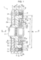
- a rotating coil type electromagnetic clutch denoted by reference numeral 1 as a whole in Fig. 1 includes a field core 3 having a rotating shaft 2 axially mounted in the central portion, an armature 4 formed by a magnetic member which rotates while interlocking with worm gears (none of which are shown) rotated/driven by a motor, and a power feeding device 5 mounted in a mounting recess portion 3a formed in the end face of the field core 3 in the arrow B direction.
- the armature 4 is formed in a ring-like shape and supported on a boss portion 3c of the field core 3 through a leaf spring 6 so as to be movable in the axial direction (arrow A - B direction) of the rotating shaft 2 and rotatable, with a frictional surface 4a facing a frictional surface 3b of the field core 3 through a slight gap.
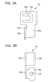
- reference numeral 10 denotes a coil terminal formed by a mounted portion 10a, a coil connection portion 10c formed by being bent at a right angle on a side portion of an extending portion 10b extending from the mounted portion 10a in the plane direction, and a terminal portion 10d folded back from an end portion of the mounted portion 10a on the side opposite to the coil connection portion 10c in a curved shape so as to be parallel to the mounted portion 10a.
- the mounted portion 10a is provided with an engaging piece 10e which is bent to incline toward the terminal portion 10d side.
- a connection hole 10f is formed in the coil connection portion 10c.
- the winding start portion or winding end portion of an exciting coil 11 is inserted in the connection hole 10f and electrically connected to the coil terminal 10 by soldering.
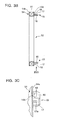
- reference numeral 12 denotes a coil bobbin having a ring-like shape as a whole.
- a coil winding portion 14 having a U-shaped cross section around which the exciting coil 11 is wound is formed by integrally forming a pair of flanges 14a and 14b.
- Mounting portions 15 on which the coil terminals 10 are mounted are integrally formed on one flange 14a at positions which are 180° out of phase from each other in the circumferential direction.
- Support pieces 16 and 17 are integrally formed upright on each mounting portion 15 so as to extend from one flange 14a and face each other.
- the gap between the support pieces 16 and 17 is slightly larger than the thickness of the mounted portion 10a of the coil terminal 10.
- One support piece 17 has an engaging hole 17a with which the engaging piece 10e of the coil terminal 10 engages.
- Reference numeral 18 denotes mounting portions on which the coil connection portion 10c of the coil terminal 10 is mounted.
- a through hole 14c through which the winding start portion or winding end portion of the exciting coil 11 extends is formed in the flange 14a of the coil winding portion 14 in correspondence with a position between the mounting portions 18.
- the coil terminals 10 are mounted on the pair of mounting portions 15 of the coil bobbin 12 as shown in Fig. 4 by inserting the mounted portion 10a of each coil terminal 10 into the gap between the support pieces 16 and 17 of the mounting portion 15 in the arrow A direction as shown in Fig. 5B and engaging the engaging piece 10e with the engaging hole 17a of the support piece 17.
- the coil connection portion 10c of the coil terminal 10 mounted on the mounting portion 15 in this manner is placed on the mounting portions 18.
- the winding start portion and winding end portion of the exciting coil 11 extend through the through hole 14c of the coil winding portion 14, pass through between the mounting portions 18, and are inserted into the connection hole 10f of the coil connection portion 10c.
- the winding start portion and winding end portion are then electrically connected to the coil terminals 10 by soldering 19.
- a ring-shaped bobbin storage groove 3e is provided in the field core 3.
- the bobbin storage groove 3e has an opening portion 3d in the end face on the side opposite to the mounting recess portion 3a.
- a pair of terminal storage holes 3f which are open on the end face side in which the mounting recess portion 3a of the field core 3 is provided are provided in portions of the bobbin storage groove 3e which are 180° out of phase from each other.
- An outer diameter R1 of the mounting recess portion 3a formed in the field core 3 is smaller than an inner diameter R2 of the bobbin storage groove 3e.
- the coil bobbin 12 is stored in the bobbin storage groove 3e from the opening portion 3d of the field core 3 to store the coil terminal 10 mounted on the mounting portion 15 in the terminal storage hole 3f so as to make the coil terminal 10 protrude in the arrow B direction.
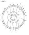
- the power feeding device 5 mainly includes first and second brushes 20 and 21, a brush holder 22 on which the first and second brushes 20 and 21 are mounted, first and second slip rings 23 and 24 which come into slidable contact with the first and second brushes 20 and 21, a ring holder 25 on which the first and second slip rings 23 and 24 are mounted, and a stopper plate 26 fixed to the brush holder 22.
- the first brush 20 is formed by a basal portion 30 formed in an almost arcuated shape in a plan view, sliding contacts 31 protruding from the two end portions of the basal portion 30 in the circumferential direction, and an extending portion 32 extending from the middle portion of the basal portion 30 in the radial direction.
- Many first through holes 30a are formed in the basal portion 30.
- each sliding contact 31 includes a plurality of contact pieces 31a which are bent to slightly tilt from the basal portion 30 in the plane direction and branch toward the distal ends.
- the distal end portions of the contact pieces 31a are provided with contact portions 31b having arcuated cross sections which come into slidable contact with the first slip ring 23.
- the extending portion 32 extends in a direction opposite to the center (rotating shaft 2) of the field core 3 while the first brush 20 is mounted on the field core 3 through the brush holder 22, and bends in a direction (the arrow B direction in Fig. 1 ) away from the coil bobbin 12 stored in the field core 3. That is, the extending portion 32 includes a first bent portion 32a bent at a right angle relative to the basal portion 30, a second bent portion 32b bent at a right angle relative to the first bent portion 32a, and a third bent portion 32c bent at a right angle relative to the second bent portion 32b. The second bent portion 32b is bent away from the coil bobbin 12 stored in the field core 3.
- the third bent portion 32c as the end portion of the extending portion 32 is parallel to the arrow A direction, i.e., the axial direction of the rotating shaft 2.
- the third bent portion 32c forms a terminal electrically connected to the terminal portion 10d of the coil terminal 10.
- the second bent portion 32b is provided with one second through hole 32d.
- the second brush 21 is formed by a basal portion 34 having an arcuated shape in a plan view, sliding contacts 35 protruding from the two end portions of the basal portion 34 in the circumferential direction, and an extending portion 36 extending from the middle portion of the basal portion 34 in the radial direction.
- Many first through holes 34a are formed in the basal portion 34.
- each sliding contact 35 includes a plurality of terminal pieces 35a which are bent to slightly tilt from the basal portion 34 in the plane direction and branch toward the distal ends. The distal end portions of the terminal pieces 35a are provided with contact portions 35b having arcuated cross sections which come into slidable contact with the second slip ring 24.
- the first and second slip rings 23 and 24 come into contact with the plurality of contact portions 31b and 35b. This reduces the contact resistance between the first and second slip rings 23 and 24 and the first and second brushes 20 and 21.
- the contact portions 31b and 35b are made to branch, which come into slidable contact with the first and second slip rings 23 and 24 of the first and second brushes 20 and 21. Even if, therefore, the first and second slip rings 23 and 24 do not have flat surfaces, the contact portions 31b and 35b elastically deform with respect to the surfaces of the first and second slip rings 23 and 24. This therefore prevents an increase in the contact resistance between the contact portions 31b and 35b and the first and second slip rings 23 and 24.
- the extending portion 36 is bent in a direction (the arrow B direction in Fig. 1 ) away from the coil bobbin 12 stored in the field core 3 while the second brush 21 is mounted on the field core 3 through the brush holder 22. That is, the extending portion 36 includes a first bent portion 36a bent at a right angle relative to the basal portion 34, a second bent portion 36b bent at a right angle relative to the first bent portion 36a, and a third bent portion 36c functioning as a terminal bent at a right angle relative to the second bent portion 36b.
- the second bent portion 36b is bent away from the coil bobbin 12 stored in the field core 3.
- the third bent portion 36c as the end portion of the extending portion 36 is parallel to the arrow A direction, i.e., the axial direction of the rotating shaft 2.
- the third bent portion 36c forms a terminal electrically connected to the terminal portion 10d of the coil terminal 10.
- the second bent portion 36b is provided with one second through hole 36d.
- a projection portion 40 which has a circular shape in a plan view and is fitted in the mounting recess portion 3a of the field core 3 described above protrudes from the central potion of the brush holder 22.
- a plurality of through holes 41 are formed around the projection portion 40.
- Support walls 42A and 42B each having a U-shaped form in a plan view, are integrally formed upright at portions on the outer periphery of the brush holder 22 which are 180° out of phase so as to face each other.
- through grooves 43A and 43B are formed in the basal portions of the support walls 42A and 42B.
- Recess portions 44A and 44B in which the second bent portions 32b and 36b of the first and second brushes 20 and 21 are fitted are formed in the lower surface of the brush holder 22 in correspondence with the support walls 42A and 42B.
- second small projections 45A and 45B protrude, which are fitted in second through holes 32d and 36d of the first and second brushes 20 and 21.
- First small projections 46A and 46B which are fitted in the first through holes 30a and 34a of the first and second brushes 20 and 21 protrude from the lower surface of the projection portion 40 of the brush holder 22 at positions near the recess portions 44A and 44B.
- the bent portion 32c of the first brush 20 is made to extend through the through groove 43A from the lower surface side of the brush holder 22, and the second bent portion 32b is fitted in the recess portion 44A, the first through holes 30a are fitted on the first small projections 46A, and the second through holes 32d are fitted on the second small projections 45A.
- the first brush 20 is mounted on the brush holder 22 by caulking the first and second small projections 46A and 45A while the third bent portion 32c is in contact opposite to the support wall 42A.
- the third bent portion 32c extending through the through groove 43A comes into contact opposite to the support wall 42A of the brush holder 22.
- the third bent portion 36c of the second brush 21 is made to extend through the through groove 43B from the lower surface side of the brush holder 22 and the second bent portion 36b is fitted in the recess portion 44B, the first through holes 34a are fitted on the first small projections 46B, and the second through holes 36d are fitted on the second small projections 45B.
- the second brush 21 is mounted on the brush holder 22 by caulking the first and second small projections 46B and 45B while the third bent portion 36c is in contact opposite to the support wall 42B.
- the third bent portion 36c extending through the through groove 43B comes into contact with the support wall 42B of the brush holder 22.
- the first and second brushes 20 and 21 are mounted on the brush holder 22 by elastically deforming the second small projections 45A and 45B fitted in the second through holes 32d and 36d formed in the second bent portions 32b and 36b of the extending portions 32 and 36 of the first and secondbrushes 20 and 21. For this reason, even if loads are applied to the first and second brushes 20 and 21 when the contact portions 31b and 35b of the first and second brushes 20 and 21 electrically come into slidable contact with the first and second slip rings 23 and 24, the first and second brushes 20 and 21 do not freely move. This can reduce the electrical contact resistance between the contact portion 31b and 35b and the first and second slip rings 23 and 24.
- the brush holder 22 is fixed to the field core 3 by fitting the projection portion 40 in the mounting recess portion 3a while fitting the support walls 42A and 42B of the brush holder 22, on which the first and second brushes 20 and 21 are mounted, in the terminal storage holes 3f of the field core 3 as shown in Fig. 1 .
- the third bent portions 32c and 36c of the first and second brushes 20 and 21 electrically come into contact with the terminal portions 10d of the coil terminals 10 along the axial direction (the arrow A - B direction) of the rotating shaft 2.
- the brush holder 22 with the support walls 42A and 42B fitted in the terminal storage holes 3f of the field core 3 allows the brush holder 22 to be positioned and mounted on the field core 3, thus facilitating mounting operation.
- the third bent portions 32c and 36c of the first and second brushes 20 and 21 are clamped between the terminal portions 10d and the support walls 42A and 42B as the terminal portions 10d of the coil terminals 10 are pressed against the support walls 42A and 42B with the elastically restoring force of the terminal portions 10d while the third bent portions 32c and 36c are in contact opposite to the support walls 42A and 42B of the brush holder 22.
- the extending portions 32 and 36 of the first and second brushes 20 and 21 are bent to separate the second bent portions 32b and 36b from the coil bobbin 12.
- the outer diameter R1 of the mounting recess portion 3a of the field core 3 is smaller than the inner diameter R2 of the coil bobbin 12. This makes it possible to position the mounting recess portion 3a at a distance H from the coil winding portion 14 of the coil bobbin 12 in the field core 3 in the arrow A direction. This can reduce the size of the rotating coil type electromagnetic clutch 1 in the arrow A - B direction.
- the first slip ring 23 has a ring-like shape and is provided with a plurality of mounting bent pieces 50 bent downward from the inner periphery and one power feeding terminal 51.
- Each mounting bent piece 50 has a bifurcated distal end portion.
- the second slip ring 24 has a ring-like shape smaller in diameter than the first slip ring 23, and is provided with a plurality of mounting bent pieces 52 bent downward from the outer periphery and one power feeding terminal 53.
- Each mounting bent piece 52 has a bifurcated distal end portion.
- the periphery of a through hole 54 provided in the central portion of the ring holder 25 has three notches 54a at equal angular intervals in the circumferential direction to fix a bearing 60 (see Fig. 1 ) which rotatably supports the rotating shaft 2.
- the peripheral portion of the ring holder 25 has through holes 56 and 58 at positions which are 180° out of phase from each other in the circumferential direction.
- the power feeding terminals 51 and 53 of the first and second slip rings 23 and 24 extend through the through holes 56 and 58.
- a plurality of fitting holes 55 and 57 are provided between the through holes 56 and 58.
- the mounting bent pieces 50 and 52 of the first and second slip rings 23 and 24 are fitted in the fitting holes 55 and 57.
- fitting the mounting bent pieces 50 of the first slip ring 23 in the fitting holes 55 of the ring holder 25 while elastically deforming the bifurcated distal end portions will mount the first slip ring 23 on the ring holder 25 so as to make the power feeding terminal 51 extend through the through hole 56, as shown in Fig. 1 .
- fitting the mounting bent pieces 52 of the second slip ring 24 in the fitting holes 57 of the ring holder 25 while elastically deforming the bifurcated distal end portions will mount the second slip ring 24 on the ring holder 25 so as to make the power feeding terminal 53 extend through the through hole 58, as shown in Fig. 1 .
- the ring holder 25 is fixed to fixing members (none of which are shown) such that the power feeding terminals 51 and 53 are fitted in the connectors on the power feeding side and electrically connected to them.
- the stopper plate 26 has a ring-like shape, and a plurality of small projections 62 are integrally formed upright on the stopper plate 26 at equal angular intervals in the circumferential direction. Fitting the small projections 62 in the through holes 41 of the brush holder 22 will mount the stopper plate 26 on the brush holder 22, thereby assembling the rotating coil type electromagnetic clutch 1, as shown in Fig. 1 .
- the rotating coil type electromagnetic clutch 1 assembled in this manner, when power is fed to the exciting coil 11 through the first and second slip rings 23 and 24 and the first and second brushes 20 and 21 which are electrically in slidable contact with the first and second slip rings 23 and 24, the armature 4 is attracted to the exciting coil 11 due to its magnetic flux so as to make the frictional surface 4a of the armature 4 frictionally engage with the frictional surface 3b of the field core 3.
- the armature 4 and the field core 3 which rotate while interlocking with worm gears (none of which are shown) rotated/driven by the motor, integrally rotate. This rotation is then transmitted to the rotating shaft 2.
Landscapes
- Engineering & Computer Science (AREA)
- General Engineering & Computer Science (AREA)
- Physics & Mathematics (AREA)
- Electromagnetism (AREA)
- Mechanical Engineering (AREA)
- Motor Or Generator Current Collectors (AREA)
- Electromagnets (AREA)
- Braking Arrangements (AREA)
- Valve Device For Special Equipments (AREA)
Abstract
Description
- The present invention relates to a rotating coil type electromagnetic clutch including an exciting coil to which power is fed from a power feeding device including a brush and a slip ring with which the brush comes into slidable contact.
- A conventional rotating coil type electromagnetic clutch is disclosed in Japanese Patent Laid-Open No.
2007-135367 reference 1 includes an annular recess groove which opens on the armature side and around which an exciting coil is wound and a field core which opens on the side opposite to the armature and is provided with a mounting recess portion in which a power feeding device is mounted, and on which a rotating shaft is axially mounted. An electrode to which the winding start portion and winding end portion of the exciting coil are connected extends through between the annular recess groove and the mounting recess portion, from the annular recess groove, to face the interior of the mounting recess portion. This electrode is electrically connected to a terminal portion of a brush of the power feeding device. Feeding power from the power feeding device to the exciting coil will rotate the field core frictionally engaging with the armature. - In the above conventional rotating coil type electromagnetic clutch, the terminal portion of the brush is exposed from the outer circumferential portion of the brush holder of the power feeding device, and the electrode facing the interior of the mounting recess portion comes into contact with the exposed terminal portion. Owing to this structure, the outer diameter of the mounting recess portion becomes larger than the inner diameter of the annular recess groove. For this reason, it is impossible to place the mounting recess portion in the space on the inner circumference of the annular recess groove. This makes it impossible to place the annular recess groove and the mounting recess portion so as not to overlap each other when viewed from a direction perpendicular to the axial direction of the rotating shaft. This imposes limitation on a reduction in the size of the field core in the axial direction.
- The present invention has been made in consideration of the above problem, and has as its object to reduce the size of the apparatus in the axial direction. Means of Solution to the Problem
- In order to achieve the above object, the present invention comprises an armature which has a frictional surface and is rotated/driven by a driving source, a field core which has a frictional surface facing the frictional surface of the armature and rotates integrally upon making the frictional surfaces frictionally engage with each other, a rotating shaft on which the field core is axially mounted, a brush holder mounted in a mounting recess portion formed in the field core, a coil bobbin which is buried in the field core, around which an exciting coil is wound, and which is formed to have an inner diameter larger than an outer diameter of the mounting recess portion, a coil terminal to which a winding start portion and winding fish end portion of the exciting coil are electrically connected and which protrudes from the coil bobbin in an axial direction of the rotating shaft, a slip ring including a power feeding terminal which feeds power to the exciting coil, a brush which is mounted on the brush holder and electrically comes into slidable contact with the slip ring, an extending portion which is integrally formed on the brush and is formed to extend in a direction opposite to the center of the field core and bend in a direction away from the coil bobbin, and a terminal which is formed on an end portion of the extending portion so as to be oriented in the axial direction of the rotating shaft and electrically is in contact with the coil terminal along the axial direction of the rotating shaft.
- According to the present invention, bending the extending portions of the brushes in a direction away from the coil bobbin can make the outer diameter of the mounting recess portion smaller than the inner diameter of the coil bobbin. Therefore, the mounting recess portion can be placed in the space on the inner circumferential side of the coil bobbin. This makes it possible to place the coil bobbin and the mounting recess portion so as to overlap each other when viewed from a direction perpendicular to the axial direction of the rotating shaft. It is therefore possible to reduce the size of the rotating coil type electromagnetic clutch in the axial direction of the rotating shaft. Brief Description of Drawings
-
-
Fig. 1 is a sectional view of a rotating coil type electromagnetic clutch according to the present invention; -
Fig. 2A is a front view of a coil terminal; -
Fig. 2B is a side view of the coil terminal; -
Fig. 2C is a bottom view of the coil terminal; -
Fig. 3A is a bottom view of a coil bobbin; -
Fig. 3B is a sectional view taken along a line III (B) - III(B) inFig. 3A ; -
Fig. 3C is a fragmentary view taken along the direction of an arrow III(C) inFig. 3B ; -
Fig. 4A is a bottom view showing a state in which the coil terminal is mounted on the coil bobbin; -
Fig. 4B is a sectional view taken along a line IV (B) - IV (B) inFig. 4A ; -
Fig. 5A is an enlarged view of a portion V(A) inFig. 4B ; -
Fig. 5B is an enlarged view of a portion V(B) inFig. 4B ; -
Fig. 6 is a fragmentary view taken along the direction of an arrow VI inFig. 5B ; -
Fig. 7A is a bottom view of a field core; -
Fig. 7B is a sectional view taken along a line VII (B) - VII(B) inFig. 7A ; -
Fig. 8 is an exploded perspective view of the power feeding device of the rotating coil type electromagnetic clutch according to the present invention; -
Fig. 9 is a bottom view of the power feeding device of the rotating coil type electromagnetic clutch according to the present invention; -
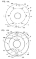
Fig. 10A is a plan view of a brush holder; -
Fig. 10B is a bottom view of the brush holder; -
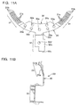
Fig. 11A is a plan view of the first brush; -
Fig. 11B is a side view of the first brush; -
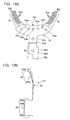
Fig. 12A is a plan view of the second brush; -
Fig. 12B is a side view of the second brush; -
Fig. 13A is a plan view of a ring holder; -
Fig. 13B is a sectional view taken along a line XIII (B) - XIII(B) inFig. 13A ; and -
Fig. 13C is a bottom view of the ring holder. - The embodiments of the present invention will be described below with reference to
Figs. 1 to 13 . - A rotating coil type electromagnetic clutch denoted by
reference numeral 1 as a whole inFig. 1 includes afield core 3 having arotating shaft 2 axially mounted in the central portion, anarmature 4 formed by a magnetic member which rotates while interlocking with worm gears (none of which are shown) rotated/driven by a motor, and apower feeding device 5 mounted in a mountingrecess portion 3a formed in the end face of thefield core 3 in the arrow B direction. Thearmature 4 is formed in a ring-like shape and supported on aboss portion 3c of thefield core 3 through aleaf spring 6 so as to be movable in the axial direction (arrow A - B direction) of therotating shaft 2 and rotatable, with africtional surface 4a facing africtional surface 3b of thefield core 3 through a slight gap. - Coil terminals will be described next with reference to
Fig. 2 , which are electrically connected to the winding start portion and winding end portion of the exciting coil. Referring toFig. 2 ,reference numeral 10 denotes a coil terminal formed by a mountedportion 10a, acoil connection portion 10c formed by being bent at a right angle on a side portion of an extendingportion 10b extending from the mountedportion 10a in the plane direction, and aterminal portion 10d folded back from an end portion of the mountedportion 10a on the side opposite to thecoil connection portion 10c in a curved shape so as to be parallel to the mountedportion 10a. The mountedportion 10a is provided with anengaging piece 10e which is bent to incline toward theterminal portion 10d side. Aconnection hole 10f is formed in thecoil connection portion 10c. The winding start portion or winding end portion of anexciting coil 11 is inserted in theconnection hole 10f and electrically connected to thecoil terminal 10 by soldering. - The coil bobbin will be described next with reference to
Fig. 3 . Referring toFig. 3 ,reference numeral 12 denotes a coil bobbin having a ring-like shape as a whole. Acoil winding portion 14 having a U-shaped cross section around which theexciting coil 11 is wound is formed by integrally forming a pair offlanges portions 15 on which thecoil terminals 10 are mounted are integrally formed on oneflange 14a at positions which are 180° out of phase from each other in the circumferential direction. -
Support pieces portion 15 so as to extend from oneflange 14a and face each other. The gap between thesupport pieces portion 10a of thecoil terminal 10. Onesupport piece 17 has anengaging hole 17a with which theengaging piece 10e of thecoil terminal 10 engages.Reference numeral 18 denotes mounting portions on which thecoil connection portion 10c of thecoil terminal 10 is mounted. A throughhole 14c through which the winding start portion or winding end portion of theexciting coil 11 extends is formed in theflange 14a of thecoil winding portion 14 in correspondence with a position between the mountingportions 18. - In this arrangement, the
coil terminals 10 are mounted on the pair of mountingportions 15 of thecoil bobbin 12 as shown inFig. 4 by inserting the mountedportion 10a of eachcoil terminal 10 into the gap between thesupport pieces portion 15 in the arrow A direction as shown inFig. 5B and engaging theengaging piece 10e with the engaginghole 17a of thesupport piece 17. As shown inFigs. 5A and6 , thecoil connection portion 10c of thecoil terminal 10 mounted on the mountingportion 15 in this manner is placed on the mountingportions 18. The winding start portion and winding end portion of theexciting coil 11 extend through the throughhole 14c of thecoil winding portion 14, pass through between the mountingportions 18, and are inserted into theconnection hole 10f of thecoil connection portion 10c. The winding start portion and winding end portion are then electrically connected to thecoil terminals 10 by soldering 19. - As shown in
Fig. 7B , a ring-shapedbobbin storage groove 3e is provided in thefield core 3. Thebobbin storage groove 3e has anopening portion 3d in the end face on the side opposite to the mountingrecess portion 3a. A pair ofterminal storage holes 3f which are open on the end face side in which the mountingrecess portion 3a of thefield core 3 is provided are provided in portions of thebobbin storage groove 3e which are 180° out of phase from each other. An outer diameter R1 of the mountingrecess portion 3a formed in thefield core 3 is smaller than an inner diameter R2 of thebobbin storage groove 3e. As shown inFig. 1 , therefore, thecoil bobbin 12 is stored in thebobbin storage groove 3e from theopening portion 3d of thefield core 3 to store thecoil terminal 10 mounted on the mountingportion 15 in theterminal storage hole 3f so as to make thecoil terminal 10 protrude in the arrow B direction. - The
power feeding device 5 will be described next with reference toFigs. 8 to 13 . As shown inFig. 8 , thepower feeding device 5 mainly includes first andsecond brushes brush holder 22 on which the first andsecond brushes second brushes ring holder 25 on which the first and second slip rings 23 and 24 are mounted, and astopper plate 26 fixed to thebrush holder 22. - As shown in
Fig. 11 , thefirst brush 20 is formed by abasal portion 30 formed in an almost arcuated shape in a plan view, slidingcontacts 31 protruding from the two end portions of thebasal portion 30 in the circumferential direction, and an extendingportion 32 extending from the middle portion of thebasal portion 30 in the radial direction. Many first throughholes 30a are formed in thebasal portion 30. As shown inFig. 11B , each slidingcontact 31 includes a plurality ofcontact pieces 31a which are bent to slightly tilt from thebasal portion 30 in the plane direction and branch toward the distal ends. The distal end portions of thecontact pieces 31a are provided withcontact portions 31b having arcuated cross sections which come into slidable contact with thefirst slip ring 23. - As described later, the extending
portion 32 extends in a direction opposite to the center (rotating shaft 2) of thefield core 3 while thefirst brush 20 is mounted on thefield core 3 through thebrush holder 22, and bends in a direction (the arrow B direction inFig. 1 ) away from thecoil bobbin 12 stored in thefield core 3. That is, the extendingportion 32 includes a firstbent portion 32a bent at a right angle relative to thebasal portion 30, a secondbent portion 32b bent at a right angle relative to the firstbent portion 32a, and a thirdbent portion 32c bent at a right angle relative to the secondbent portion 32b. The secondbent portion 32b is bent away from thecoil bobbin 12 stored in thefield core 3. Therefore, the thirdbent portion 32c as the end portion of the extendingportion 32 is parallel to the arrow A direction, i.e., the axial direction of therotating shaft 2. The thirdbent portion 32c forms a terminal electrically connected to theterminal portion 10d of thecoil terminal 10. The secondbent portion 32b is provided with one second throughhole 32d. - As shown in
Fig. 12 , thesecond brush 21 is formed by abasal portion 34 having an arcuated shape in a plan view, slidingcontacts 35 protruding from the two end portions of thebasal portion 34 in the circumferential direction, and an extendingportion 36 extending from the middle portion of thebasal portion 34 in the radial direction. Many first throughholes 34a are formed in thebasal portion 34. As shown inFig. 12B , each slidingcontact 35 includes a plurality ofterminal pieces 35a which are bent to slightly tilt from thebasal portion 34 in the plane direction and branch toward the distal ends. The distal end portions of theterminal pieces 35a are provided withcontact portions 35b having arcuated cross sections which come into slidable contact with thesecond slip ring 24. - As described above, the first and second slip rings 23 and 24 come into contact with the plurality of
contact portions second brushes contact portions second brushes contact portions contact portions - As described later, the extending
portion 36 is bent in a direction (the arrow B direction inFig. 1 ) away from thecoil bobbin 12 stored in thefield core 3 while thesecond brush 21 is mounted on thefield core 3 through thebrush holder 22. That is, the extendingportion 36 includes a firstbent portion 36a bent at a right angle relative to thebasal portion 34, a secondbent portion 36b bent at a right angle relative to the firstbent portion 36a, and a thirdbent portion 36c functioning as a terminal bent at a right angle relative to the secondbent portion 36b. The secondbent portion 36b is bent away from thecoil bobbin 12 stored in thefield core 3. Therefore, the thirdbent portion 36c as the end portion of the extendingportion 36 is parallel to the arrow A direction, i.e., the axial direction of therotating shaft 2. The thirdbent portion 36c forms a terminal electrically connected to theterminal portion 10d of thecoil terminal 10. The secondbent portion 36b is provided with one second throughhole 36d. - As shown in
Fig. 8 , aprojection portion 40 which has a circular shape in a plan view and is fitted in the mountingrecess portion 3a of thefield core 3 described above protrudes from the central potion of thebrush holder 22. A plurality of throughholes 41 are formed around theprojection portion 40.Support walls brush holder 22 which are 180° out of phase so as to face each other. As shown inFig. 10 , throughgrooves support walls -
Recess portions bent portions second brushes brush holder 22 in correspondence with thesupport walls recess portions small projections holes second brushes small projections holes second brushes projection portion 40 of thebrush holder 22 at positions near therecess portions - In this arrangement, when the
bent portion 32c of thefirst brush 20 is made to extend through the throughgroove 43A from the lower surface side of thebrush holder 22, and the secondbent portion 32b is fitted in therecess portion 44A, the first throughholes 30a are fitted on the firstsmall projections 46A, and the second throughholes 32d are fitted on the secondsmall projections 45A. In this state, thefirst brush 20 is mounted on thebrush holder 22 by caulking the first and secondsmall projections bent portion 32c is in contact opposite to thesupport wall 42A. In this case, the thirdbent portion 32c extending through the throughgroove 43A comes into contact opposite to thesupport wall 42A of thebrush holder 22. - Likewise, when the third
bent portion 36c of thesecond brush 21 is made to extend through the throughgroove 43B from the lower surface side of thebrush holder 22 and the secondbent portion 36b is fitted in therecess portion 44B, the first throughholes 34a are fitted on the firstsmall projections 46B, and the second throughholes 36d are fitted on the secondsmall projections 45B. In this state, thesecond brush 21 is mounted on thebrush holder 22 by caulking the first and secondsmall projections bent portion 36c is in contact opposite to thesupport wall 42B. In this case, the thirdbent portion 36c extending through the throughgroove 43B comes into contact with thesupport wall 42B of thebrush holder 22. - In this manner, the first and
second brushes brush holder 22 by elastically deforming the secondsmall projections holes bent portions portions second brushes contact portions second brushes second brushes contact portion - The
brush holder 22 is fixed to thefield core 3 by fitting theprojection portion 40 in the mountingrecess portion 3a while fitting thesupport walls brush holder 22, on which the first andsecond brushes terminal storage holes 3f of thefield core 3 as shown inFig. 1 . In this state, the thirdbent portions second brushes terminal portions 10d of thecoil terminals 10 along the axial direction (the arrow A - B direction) of therotating shaft 2. - Providing the
brush holder 22 with thesupport walls terminal storage holes 3f of thefield core 3 allows thebrush holder 22 to be positioned and mounted on thefield core 3, thus facilitating mounting operation. In addition, the thirdbent portions second brushes terminal portions 10d and thesupport walls terminal portions 10d of thecoil terminals 10 are pressed against thesupport walls terminal portions 10d while the thirdbent portions support walls brush holder 22. This makes the thirdbent portions terminal portions 10d, and hence can reduce the electrical contact resistance between them. - In this case, the extending
portions second brushes bent portions coil bobbin 12. As described above, the outer diameter R1 of the mountingrecess portion 3a of thefield core 3 is smaller than the inner diameter R2 of thecoil bobbin 12. This makes it possible to position the mountingrecess portion 3a at a distance H from thecoil winding portion 14 of thecoil bobbin 12 in thefield core 3 in the arrow A direction. This can reduce the size of the rotating coil typeelectromagnetic clutch 1 in the arrow A - B direction. - As shown in
Fig. 8 , thefirst slip ring 23 has a ring-like shape and is provided with a plurality of mountingbent pieces 50 bent downward from the inner periphery and onepower feeding terminal 51. Each mountingbent piece 50 has a bifurcated distal end portion. As shown inFig. 8 , thesecond slip ring 24 has a ring-like shape smaller in diameter than thefirst slip ring 23, and is provided with a plurality of mountingbent pieces 52 bent downward from the outer periphery and onepower feeding terminal 53. Each mountingbent piece 52 has a bifurcated distal end portion. - As shown in
Fig. 13C , the periphery of a throughhole 54 provided in the central portion of thering holder 25 has threenotches 54a at equal angular intervals in the circumferential direction to fix a bearing 60 (seeFig. 1 ) which rotatably supports therotating shaft 2. In addition, the peripheral portion of thering holder 25 has throughholes power feeding terminals holes fitting holes holes bent pieces - In this arrangement, fitting the mounting
bent pieces 50 of thefirst slip ring 23 in the fitting holes 55 of thering holder 25 while elastically deforming the bifurcated distal end portions will mount thefirst slip ring 23 on thering holder 25 so as to make thepower feeding terminal 51 extend through the throughhole 56, as shown inFig. 1 . Likewise, fitting the mountingbent pieces 52 of thesecond slip ring 24 in the fitting holes 57 of thering holder 25 while elastically deforming the bifurcated distal end portions will mount thesecond slip ring 24 on thering holder 25 so as to make thepower feeding terminal 53 extend through the throughhole 58, as shown inFig. 1 . Thering holder 25 is fixed to fixing members (none of which are shown) such that thepower feeding terminals - As shown in
Fig. 8 , thestopper plate 26 has a ring-like shape, and a plurality ofsmall projections 62 are integrally formed upright on thestopper plate 26 at equal angular intervals in the circumferential direction. Fitting thesmall projections 62 in the throughholes 41 of thebrush holder 22 will mount thestopper plate 26 on thebrush holder 22, thereby assembling the rotating coil typeelectromagnetic clutch 1, as shown inFig. 1 . In the rotating coil typeelectromagnetic clutch 1 assembled in this manner, when power is fed to theexciting coil 11 through the first and second slip rings 23 and 24 and the first andsecond brushes armature 4 is attracted to theexciting coil 11 due to its magnetic flux so as to make thefrictional surface 4a of thearmature 4 frictionally engage with thefrictional surface 3b of thefield core 3. As a consequence, thearmature 4 and thefield core 3, which rotate while interlocking with worm gears (none of which are shown) rotated/driven by the motor, integrally rotate. This rotation is then transmitted to therotating shaft 2.
Claims (5)
- A rotating coil type electromagnetic clutch comprising:an armature which has a frictional surface and is rotated/driven by a driving source;a field core which has a frictional surface facing the frictional surface of said armature and rotates integrally upon making the frictional surfaces frictionally engage with each other;a rotating shaft on which said field core is axially mounted;a brush holder mounted in a mounting recess portion formed in said field core;a coil bobbin which is buried in said field core, around which an exciting coil is wound, and which is formed to have an inner diameter larger than an outer diameter of the mounting recess portion;coil terminals to which a winding start portion and winding fish end portion of the exciting coil are electrically connected and which protrude from said coil bobbin in an axial direction of said rotating shaft;slip rings including power feeding terminals which feed power to the exciting coil;brushes which are mounted on said brush holder and electrically come into slidable contact with said slip ring;extending portions which are integrally formed on said brush and is formed to extend in a direction opposite to the center of said field core and bend in a direction away from said coil bobbin; andterminals which are formed on an end portions of said extending portions so as to be oriented in the axial direction of said rotating shaft and electrically are in contact with said coil terminals along the axial direction of said rotating shaft.
- A rotating coil type electromagnetic clutch according to claim 1, further comprising:through holes formed in said extending portions of said brushes; andprojections which protrude from said brush holder, are fitted in said through holes, and are elastically deformed to mount said brushes on said brush holder.
- A rotating coil type electromagnetic clutch according to claim 1, further comprising a plurality of branched contact portions on portions of said brushes which come into slidable contact with said slip rings.
- A rotating coil type electromagnetic clutch according to claim 1, further comprising:a pair of terminal storage holes which are formed in said field core and store said coil terminals;a pair of support walls which are formed upright on said brush holder and respectively fitted in the pair of terminal storage holes.
- The rotating coil type electromagnetic clutch according to claim 4, further comprising through grooves in portions of said brush holder which correspond to said support walls,
wherein terminals of said brush which extend through said through grooves are in contact with said support walls, and said coil terminals and said support walls clamp the terminals of said brush.
Applications Claiming Priority (2)
| Application Number | Priority Date | Filing Date | Title |
|---|---|---|---|
| JP2008223326A JP5149108B2 (en) | 2008-09-01 | 2008-09-01 | Coil rotating electromagnetic clutch |
| PCT/JP2009/065237 WO2010024443A1 (en) | 2008-09-01 | 2009-09-01 | Coil rotation type electromagnetic clutch |
Publications (3)
| Publication Number | Publication Date |
|---|---|
| EP2333369A1 true EP2333369A1 (en) | 2011-06-15 |
| EP2333369A4 EP2333369A4 (en) | 2011-08-17 |
| EP2333369B1 EP2333369B1 (en) | 2012-03-21 |
Family
ID=41721602
Family Applications (1)
| Application Number | Title | Priority Date | Filing Date |
|---|---|---|---|
| EP09810087A Not-in-force EP2333369B1 (en) | 2008-09-01 | 2009-09-01 | Coil rotation type electromagnetic clutch |
Country Status (6)
| Country | Link |
|---|---|
| US (1) | US8011488B2 (en) |
| EP (1) | EP2333369B1 (en) |
| JP (1) | JP5149108B2 (en) |
| CN (1) | CN102089544B (en) |
| AT (1) | ATE550564T1 (en) |
| WO (1) | WO2010024443A1 (en) |
Families Citing this family (5)
| Publication number | Priority date | Publication date | Assignee | Title |
|---|---|---|---|---|
| JP5995655B2 (en) * | 2012-10-23 | 2016-09-21 | 小倉クラッチ株式会社 | Electromagnetic coupling device |
| US20160223031A1 (en) * | 2015-02-02 | 2016-08-04 | Stephenson Gobin Limited | Clutch apparatus |
| JP6519310B2 (en) * | 2015-05-13 | 2019-05-29 | 株式会社ジェイテクト | Electromagnetic friction engagement device |
| JP2017131386A (en) * | 2016-01-27 | 2017-08-03 | 京楽産業.株式会社 | Game machine |
| CN108468725A (en) * | 2018-04-17 | 2018-08-31 | 苏州奥沃汽车配件有限公司 | A kind of lightweight electromagnetic fan clutch |
Family Cites Families (11)
| Publication number | Priority date | Publication date | Assignee | Title |
|---|---|---|---|---|
| IT1301914B1 (en) * | 1997-08-26 | 2000-07-07 | Denso Corp | ELECTROMAGNETIC CONNECTION. |
| JPH11132256A (en) * | 1997-10-29 | 1999-05-18 | Denso Corp | Electromagnetic clutch |
| JP2000213562A (en) * | 1999-01-27 | 2000-08-02 | Denso Corp | Electromagnetic clutch |
| JP2002315267A (en) * | 2001-04-13 | 2002-10-25 | Sankyo Seiki Mfg Co Ltd | Brush device of motor |
| JP2005248584A (en) | 2004-03-04 | 2005-09-15 | Mitsuba Corp | Automatic opening/closing apparatus for vehicle |
| JP4789539B2 (en) * | 2005-08-05 | 2011-10-12 | アイシン精機株式会社 | Drive device |
| JP4648825B2 (en) * | 2005-11-14 | 2011-03-09 | 矢崎総業株式会社 | Power supply device |
| JP2007139028A (en) * | 2005-11-16 | 2007-06-07 | Aisin Seiki Co Ltd | Electromagnetic clutch device |
| JP4831416B2 (en) | 2006-11-07 | 2011-12-07 | アイシン精機株式会社 | Electromagnetic clutch device |
| CN101772655B (en) | 2007-11-15 | 2012-06-20 | 爱信精机株式会社 | Electromagnetic clutch |
| DE112009001928T5 (en) | 2008-07-02 | 2011-06-30 | Aisin Seiki Kabushiki Kaisha, Aichi-ken | Electromagnetic clutch, ring holder and method for placing the ring holder |
-
2008
- 2008-09-01 JP JP2008223326A patent/JP5149108B2/en not_active Expired - Fee Related
-
2009
- 2009-09-01 US US13/054,936 patent/US8011488B2/en not_active Expired - Fee Related
- 2009-09-01 WO PCT/JP2009/065237 patent/WO2010024443A1/en not_active Ceased
- 2009-09-01 AT AT09810087T patent/ATE550564T1/en active
- 2009-09-01 EP EP09810087A patent/EP2333369B1/en not_active Not-in-force
- 2009-09-01 CN CN2009801266141A patent/CN102089544B/en not_active Expired - Fee Related
Non-Patent Citations (2)
| Title |
|---|
| No further relevant documents disclosed * |
| See also references of WO2010024443A1 * |
Also Published As
| Publication number | Publication date |
|---|---|
| CN102089544A (en) | 2011-06-08 |
| CN102089544B (en) | 2013-07-03 |
| EP2333369A4 (en) | 2011-08-17 |
| US20110139569A1 (en) | 2011-06-16 |
| ATE550564T1 (en) | 2012-04-15 |
| EP2333369B1 (en) | 2012-03-21 |
| WO2010024443A1 (en) | 2010-03-04 |
| JP2010059984A (en) | 2010-03-18 |
| JP5149108B2 (en) | 2013-02-20 |
| US8011488B2 (en) | 2011-09-06 |
Similar Documents
| Publication | Publication Date | Title |
|---|---|---|
| EP2333369B1 (en) | Coil rotation type electromagnetic clutch | |
| US11616425B2 (en) | Ground terminal, cover assembly and motor comprising same | |
| US8978496B2 (en) | Step actuator | |
| WO2009118972A1 (en) | Dc motor | |
| JP2015043685A (en) | Motor | |
| CN111033958A (en) | motor | |
| CN110462987A (en) | motor | |
| US20110011697A1 (en) | Electromagnetic clutch, ring holder and method of manufacturing the ring holder | |
| JP2007288977A (en) | Rotor, brushless motor, and rotor manufacturing method | |
| CN102403859B (en) | Dc motor | |
| JP3130230B2 (en) | Exciter for electromagnetic coupling device | |
| JP4563864B2 (en) | Brush holder and motor | |
| JP4648825B2 (en) | Power supply device | |
| JP6209060B2 (en) | Inductor type motor | |
| JP2010207025A (en) | Motor | |
| JP4524765B2 (en) | Electromagnetic clutch | |
| JP6626785B2 (en) | Electric motor and electric motor assembling method | |
| JP5141861B2 (en) | Stepping motor | |
| JP2021136758A (en) | Brush holder and motor | |
| JP2020137316A (en) | motor | |
| JP2020137317A (en) | motor | |
| JP2020137313A (en) | motor | |
| JP4718878B2 (en) | Pump motor | |
| JP2011010456A (en) | Dc motor | |
| JP2009273265A (en) | Armature and dc motor |
Legal Events
| Date | Code | Title | Description |
|---|---|---|---|
| PUAI | Public reference made under article 153(3) epc to a published international application that has entered the european phase |
Free format text: ORIGINAL CODE: 0009012 |
|
| 17P | Request for examination filed |
Effective date: 20110401 |
|
| AK | Designated contracting states |
Kind code of ref document: A1 Designated state(s): AT BE BG CH CY CZ DE DK EE ES FI FR GB GR HR HU IE IS IT LI LT LU LV MC MK MT NL NO PL PT RO SE SI SK SM TR |
|
| AX | Request for extension of the european patent |
Extension state: AL BA RS |
|
| A4 | Supplementary search report drawn up and despatched |
Effective date: 20110714 |
|
| RIC1 | Information provided on ipc code assigned before grant |
Ipc: F16D 27/02 20060101AFI20110708BHEP |
|
| GRAP | Despatch of communication of intention to grant a patent |
Free format text: ORIGINAL CODE: EPIDOSNIGR1 |
|
| DAX | Request for extension of the european patent (deleted) | ||
| GRAS | Grant fee paid |
Free format text: ORIGINAL CODE: EPIDOSNIGR3 |
|
| GRAA | (expected) grant |
Free format text: ORIGINAL CODE: 0009210 |
|
| AK | Designated contracting states |
Kind code of ref document: B1 Designated state(s): AT BE BG CH CY CZ DE DK EE ES FI FR GB GR HR HU IE IS IT LI LT LU LV MC MK MT NL NO PL PT RO SE SI SK SM TR |
|
| REG | Reference to a national code |
Ref country code: GB Ref legal event code: FG4D |
|
| REG | Reference to a national code |
Ref country code: CH Ref legal event code: EP |
|
| REG | Reference to a national code |
Ref country code: IE Ref legal event code: FG4D |
|
| REG | Reference to a national code |
Ref country code: AT Ref legal event code: REF Ref document number: 550564 Country of ref document: AT Kind code of ref document: T Effective date: 20120415 |
|
| REG | Reference to a national code |
Ref country code: DE Ref legal event code: R096 Ref document number: 602009006057 Country of ref document: DE Effective date: 20120516 |
|
| REG | Reference to a national code |
Ref country code: NL Ref legal event code: VDEP Effective date: 20120321 |
|
| PG25 | Lapsed in a contracting state [announced via postgrant information from national office to epo] |
Ref country code: NO Free format text: LAPSE BECAUSE OF FAILURE TO SUBMIT A TRANSLATION OF THE DESCRIPTION OR TO PAY THE FEE WITHIN THE PRESCRIBED TIME-LIMIT Effective date: 20120621 Ref country code: LT Free format text: LAPSE BECAUSE OF FAILURE TO SUBMIT A TRANSLATION OF THE DESCRIPTION OR TO PAY THE FEE WITHIN THE PRESCRIBED TIME-LIMIT Effective date: 20120321 Ref country code: HR Free format text: LAPSE BECAUSE OF FAILURE TO SUBMIT A TRANSLATION OF THE DESCRIPTION OR TO PAY THE FEE WITHIN THE PRESCRIBED TIME-LIMIT Effective date: 20120321 |
|
| LTIE | Lt: invalidation of european patent or patent extension |
Effective date: 20120321 |
|
| PG25 | Lapsed in a contracting state [announced via postgrant information from national office to epo] |
Ref country code: GR Free format text: LAPSE BECAUSE OF FAILURE TO SUBMIT A TRANSLATION OF THE DESCRIPTION OR TO PAY THE FEE WITHIN THE PRESCRIBED TIME-LIMIT Effective date: 20120622 Ref country code: FI Free format text: LAPSE BECAUSE OF FAILURE TO SUBMIT A TRANSLATION OF THE DESCRIPTION OR TO PAY THE FEE WITHIN THE PRESCRIBED TIME-LIMIT Effective date: 20120321 Ref country code: LV Free format text: LAPSE BECAUSE OF FAILURE TO SUBMIT A TRANSLATION OF THE DESCRIPTION OR TO PAY THE FEE WITHIN THE PRESCRIBED TIME-LIMIT Effective date: 20120321 |
|
| REG | Reference to a national code |
Ref country code: AT Ref legal event code: MK05 Ref document number: 550564 Country of ref document: AT Kind code of ref document: T Effective date: 20120321 |
|
| PG25 | Lapsed in a contracting state [announced via postgrant information from national office to epo] |
Ref country code: CY Free format text: LAPSE BECAUSE OF FAILURE TO SUBMIT A TRANSLATION OF THE DESCRIPTION OR TO PAY THE FEE WITHIN THE PRESCRIBED TIME-LIMIT Effective date: 20120321 |
|
| PG25 | Lapsed in a contracting state [announced via postgrant information from national office to epo] |
Ref country code: RO Free format text: LAPSE BECAUSE OF FAILURE TO SUBMIT A TRANSLATION OF THE DESCRIPTION OR TO PAY THE FEE WITHIN THE PRESCRIBED TIME-LIMIT Effective date: 20120321 Ref country code: IS Free format text: LAPSE BECAUSE OF FAILURE TO SUBMIT A TRANSLATION OF THE DESCRIPTION OR TO PAY THE FEE WITHIN THE PRESCRIBED TIME-LIMIT Effective date: 20120721 Ref country code: PL Free format text: LAPSE BECAUSE OF FAILURE TO SUBMIT A TRANSLATION OF THE DESCRIPTION OR TO PAY THE FEE WITHIN THE PRESCRIBED TIME-LIMIT Effective date: 20120321 Ref country code: SI Free format text: LAPSE BECAUSE OF FAILURE TO SUBMIT A TRANSLATION OF THE DESCRIPTION OR TO PAY THE FEE WITHIN THE PRESCRIBED TIME-LIMIT Effective date: 20120321 Ref country code: SE Free format text: LAPSE BECAUSE OF FAILURE TO SUBMIT A TRANSLATION OF THE DESCRIPTION OR TO PAY THE FEE WITHIN THE PRESCRIBED TIME-LIMIT Effective date: 20120321 Ref country code: CZ Free format text: LAPSE BECAUSE OF FAILURE TO SUBMIT A TRANSLATION OF THE DESCRIPTION OR TO PAY THE FEE WITHIN THE PRESCRIBED TIME-LIMIT Effective date: 20120321 Ref country code: BE Free format text: LAPSE BECAUSE OF FAILURE TO SUBMIT A TRANSLATION OF THE DESCRIPTION OR TO PAY THE FEE WITHIN THE PRESCRIBED TIME-LIMIT Effective date: 20120321 Ref country code: EE Free format text: LAPSE BECAUSE OF FAILURE TO SUBMIT A TRANSLATION OF THE DESCRIPTION OR TO PAY THE FEE WITHIN THE PRESCRIBED TIME-LIMIT Effective date: 20120321 |
|
| PG25 | Lapsed in a contracting state [announced via postgrant information from national office to epo] |
Ref country code: SK Free format text: LAPSE BECAUSE OF FAILURE TO SUBMIT A TRANSLATION OF THE DESCRIPTION OR TO PAY THE FEE WITHIN THE PRESCRIBED TIME-LIMIT Effective date: 20120321 Ref country code: PT Free format text: LAPSE BECAUSE OF FAILURE TO SUBMIT A TRANSLATION OF THE DESCRIPTION OR TO PAY THE FEE WITHIN THE PRESCRIBED TIME-LIMIT Effective date: 20120723 |
|
| PLBE | No opposition filed within time limit |
Free format text: ORIGINAL CODE: 0009261 |
|
| STAA | Information on the status of an ep patent application or granted ep patent |
Free format text: STATUS: NO OPPOSITION FILED WITHIN TIME LIMIT |
|
| PG25 | Lapsed in a contracting state [announced via postgrant information from national office to epo] |
Ref country code: NL Free format text: LAPSE BECAUSE OF FAILURE TO SUBMIT A TRANSLATION OF THE DESCRIPTION OR TO PAY THE FEE WITHIN THE PRESCRIBED TIME-LIMIT Effective date: 20120321 Ref country code: AT Free format text: LAPSE BECAUSE OF FAILURE TO SUBMIT A TRANSLATION OF THE DESCRIPTION OR TO PAY THE FEE WITHIN THE PRESCRIBED TIME-LIMIT Effective date: 20120321 Ref country code: DK Free format text: LAPSE BECAUSE OF FAILURE TO SUBMIT A TRANSLATION OF THE DESCRIPTION OR TO PAY THE FEE WITHIN THE PRESCRIBED TIME-LIMIT Effective date: 20120321 |
|
| 26N | No opposition filed |
Effective date: 20130102 |
|
| PG25 | Lapsed in a contracting state [announced via postgrant information from national office to epo] |
Ref country code: IT Free format text: LAPSE BECAUSE OF FAILURE TO SUBMIT A TRANSLATION OF THE DESCRIPTION OR TO PAY THE FEE WITHIN THE PRESCRIBED TIME-LIMIT Effective date: 20120321 |
|
| REG | Reference to a national code |
Ref country code: DE Ref legal event code: R097 Ref document number: 602009006057 Country of ref document: DE Effective date: 20130102 |
|
| PG25 | Lapsed in a contracting state [announced via postgrant information from national office to epo] |
Ref country code: ES Free format text: LAPSE BECAUSE OF FAILURE TO SUBMIT A TRANSLATION OF THE DESCRIPTION OR TO PAY THE FEE WITHIN THE PRESCRIBED TIME-LIMIT Effective date: 20120702 Ref country code: MC Free format text: LAPSE BECAUSE OF NON-PAYMENT OF DUE FEES Effective date: 20120930 |
|
| REG | Reference to a national code |
Ref country code: IE Ref legal event code: MM4A |
|
| PG25 | Lapsed in a contracting state [announced via postgrant information from national office to epo] |
Ref country code: BG Free format text: LAPSE BECAUSE OF FAILURE TO SUBMIT A TRANSLATION OF THE DESCRIPTION OR TO PAY THE FEE WITHIN THE PRESCRIBED TIME-LIMIT Effective date: 20120621 Ref country code: IE Free format text: LAPSE BECAUSE OF NON-PAYMENT OF DUE FEES Effective date: 20120901 |
|
| PG25 | Lapsed in a contracting state [announced via postgrant information from national office to epo] |
Ref country code: MT Free format text: LAPSE BECAUSE OF FAILURE TO SUBMIT A TRANSLATION OF THE DESCRIPTION OR TO PAY THE FEE WITHIN THE PRESCRIBED TIME-LIMIT Effective date: 20120321 |
|
| PG25 | Lapsed in a contracting state [announced via postgrant information from national office to epo] |
Ref country code: TR Free format text: LAPSE BECAUSE OF FAILURE TO SUBMIT A TRANSLATION OF THE DESCRIPTION OR TO PAY THE FEE WITHIN THE PRESCRIBED TIME-LIMIT Effective date: 20120321 |
|
| REG | Reference to a national code |
Ref country code: CH Ref legal event code: PL |
|
| GBPC | Gb: european patent ceased through non-payment of renewal fee |
Effective date: 20130901 |
|
| PG25 | Lapsed in a contracting state [announced via postgrant information from national office to epo] |
Ref country code: SM Free format text: LAPSE BECAUSE OF FAILURE TO SUBMIT A TRANSLATION OF THE DESCRIPTION OR TO PAY THE FEE WITHIN THE PRESCRIBED TIME-LIMIT Effective date: 20120321 Ref country code: LU Free format text: LAPSE BECAUSE OF NON-PAYMENT OF DUE FEES Effective date: 20120901 |
|
| PG25 | Lapsed in a contracting state [announced via postgrant information from national office to epo] |
Ref country code: GB Free format text: LAPSE BECAUSE OF NON-PAYMENT OF DUE FEES Effective date: 20130901 Ref country code: CH Free format text: LAPSE BECAUSE OF NON-PAYMENT OF DUE FEES Effective date: 20130930 Ref country code: LI Free format text: LAPSE BECAUSE OF NON-PAYMENT OF DUE FEES Effective date: 20130930 Ref country code: HU Free format text: LAPSE BECAUSE OF FAILURE TO SUBMIT A TRANSLATION OF THE DESCRIPTION OR TO PAY THE FEE WITHIN THE PRESCRIBED TIME-LIMIT Effective date: 20090901 |
|
| PG25 | Lapsed in a contracting state [announced via postgrant information from national office to epo] |
Ref country code: MK Free format text: LAPSE BECAUSE OF FAILURE TO SUBMIT A TRANSLATION OF THE DESCRIPTION OR TO PAY THE FEE WITHIN THE PRESCRIBED TIME-LIMIT Effective date: 20120321 |
|
| REG | Reference to a national code |
Ref country code: FR Ref legal event code: PLFP Year of fee payment: 8 |
|
| REG | Reference to a national code |
Ref country code: FR Ref legal event code: PLFP Year of fee payment: 9 |
|
| REG | Reference to a national code |
Ref country code: FR Ref legal event code: PLFP Year of fee payment: 10 |
|
| PGFP | Annual fee paid to national office [announced via postgrant information from national office to epo] |
Ref country code: FR Payment date: 20200928 Year of fee payment: 12 |
|
| PGFP | Annual fee paid to national office [announced via postgrant information from national office to epo] |
Ref country code: DE Payment date: 20200930 Year of fee payment: 12 |
|
| REG | Reference to a national code |
Ref country code: DE Ref legal event code: R119 Ref document number: 602009006057 Country of ref document: DE |
|
| PG25 | Lapsed in a contracting state [announced via postgrant information from national office to epo] |
Ref country code: FR Free format text: LAPSE BECAUSE OF NON-PAYMENT OF DUE FEES Effective date: 20210930 Ref country code: DE Free format text: LAPSE BECAUSE OF NON-PAYMENT OF DUE FEES Effective date: 20220401 |