EP2333358B1 - Befestigungsvorrichtung - Google Patents
Befestigungsvorrichtung Download PDFInfo
- Publication number
- EP2333358B1 EP2333358B1 EP10014730.5A EP10014730A EP2333358B1 EP 2333358 B1 EP2333358 B1 EP 2333358B1 EP 10014730 A EP10014730 A EP 10014730A EP 2333358 B1 EP2333358 B1 EP 2333358B1
- Authority
- EP
- European Patent Office
- Prior art keywords
- nut body
- washer
- accordance
- disc
- aforementioned
- Prior art date
- Legal status (The legal status is an assumption and is not a legal conclusion. Google has not performed a legal analysis and makes no representation as to the accuracy of the status listed.)
- Active
Links
Images


Classifications
-
- F—MECHANICAL ENGINEERING; LIGHTING; HEATING; WEAPONS; BLASTING
- F01—MACHINES OR ENGINES IN GENERAL; ENGINE PLANTS IN GENERAL; STEAM ENGINES
- F01N—GAS-FLOW SILENCERS OR EXHAUST APPARATUS FOR MACHINES OR ENGINES IN GENERAL; GAS-FLOW SILENCERS OR EXHAUST APPARATUS FOR INTERNAL-COMBUSTION ENGINES
- F01N13/00—Exhaust or silencing apparatus characterised by constructional features
- F01N13/18—Construction facilitating manufacture, assembly, or disassembly
- F01N13/1838—Construction facilitating manufacture, assembly, or disassembly characterised by the type of connection between parts of exhaust or silencing apparatus, e.g. between housing and tubes, between tubes and baffles
- F01N13/1844—Mechanical joints
- F01N13/1855—Mechanical joints the connection being realised by using bolts, screws, rivets or the like
-
- F—MECHANICAL ENGINEERING; LIGHTING; HEATING; WEAPONS; BLASTING
- F01—MACHINES OR ENGINES IN GENERAL; ENGINE PLANTS IN GENERAL; STEAM ENGINES
- F01N—GAS-FLOW SILENCERS OR EXHAUST APPARATUS FOR MACHINES OR ENGINES IN GENERAL; GAS-FLOW SILENCERS OR EXHAUST APPARATUS FOR INTERNAL-COMBUSTION ENGINES
- F01N13/00—Exhaust or silencing apparatus characterised by constructional features
- F01N13/18—Construction facilitating manufacture, assembly, or disassembly
- F01N13/1805—Fixing exhaust manifolds, exhaust pipes or pipe sections to each other, to engine or to vehicle body
-
- F—MECHANICAL ENGINEERING; LIGHTING; HEATING; WEAPONS; BLASTING
- F16—ENGINEERING ELEMENTS AND UNITS; GENERAL MEASURES FOR PRODUCING AND MAINTAINING EFFECTIVE FUNCTIONING OF MACHINES OR INSTALLATIONS; THERMAL INSULATION IN GENERAL
- F16B—DEVICES FOR FASTENING OR SECURING CONSTRUCTIONAL ELEMENTS OR MACHINE PARTS TOGETHER, e.g. NAILS, BOLTS, CIRCLIPS, CLAMPS, CLIPS OR WEDGES; JOINTS OR JOINTING
- F16B39/00—Locking of screws, bolts or nuts
- F16B39/22—Locking of screws, bolts or nuts in which the locking takes place during screwing down or tightening
- F16B39/28—Locking of screws, bolts or nuts in which the locking takes place during screwing down or tightening by special members on, or shape of, the nut or bolt
- F16B39/282—Locking by means of special shape of work-engaging surfaces, e.g. notched or toothed nuts
-
- F—MECHANICAL ENGINEERING; LIGHTING; HEATING; WEAPONS; BLASTING
- F16—ENGINEERING ELEMENTS AND UNITS; GENERAL MEASURES FOR PRODUCING AND MAINTAINING EFFECTIVE FUNCTIONING OF MACHINES OR INSTALLATIONS; THERMAL INSULATION IN GENERAL
- F16B—DEVICES FOR FASTENING OR SECURING CONSTRUCTIONAL ELEMENTS OR MACHINE PARTS TOGETHER, e.g. NAILS, BOLTS, CIRCLIPS, CLAMPS, CLIPS OR WEDGES; JOINTS OR JOINTING
- F16B33/00—Features common to bolt and nut
- F16B33/06—Surface treatment of parts furnished with screw-thread, e.g. for preventing seizure or fretting
-
- F—MECHANICAL ENGINEERING; LIGHTING; HEATING; WEAPONS; BLASTING
- F16—ENGINEERING ELEMENTS AND UNITS; GENERAL MEASURES FOR PRODUCING AND MAINTAINING EFFECTIVE FUNCTIONING OF MACHINES OR INSTALLATIONS; THERMAL INSULATION IN GENERAL
- F16B—DEVICES FOR FASTENING OR SECURING CONSTRUCTIONAL ELEMENTS OR MACHINE PARTS TOGETHER, e.g. NAILS, BOLTS, CIRCLIPS, CLAMPS, CLIPS OR WEDGES; JOINTS OR JOINTING
- F16B41/00—Measures against loss of bolts, nuts, or pins; Measures against unauthorised operation of bolts, nuts or pins
- F16B41/002—Measures against loss of bolts, nuts or pins
Definitions
- the invention relates to a device for fastening an exhaust manifold to an engine block according to claim 1.
- the attachment of an exhaust manifold on the engine block is generally done by screwing nuts on stud bolts screwed into the engine block.
- the nuts used are often made of heat-resistant materials and are mechanically and thermally decoupled from the manifold via sliding disks. This decoupling is necessary because the manifold expands thermally and this change in length without decoupling can cause loosening of the screw. Instead of sliding discs often perforated strips are used, which serve the simultaneous decoupling of several nuts.
- the invention aims to remedy this situation.
- the invention is based on the object to provide a device for fastening an exhaust manifold to an engine block, in which no separate sliding washer is required. According to the invention, this object is solved by the features of claim 1.
- an apparatus for mounting an exhaust manifold is provided to an engine block which does not require a separate sliding washer.
- the decoupling of the nut is achieved in that a high coefficient of friction is applied between the nut body and the disc.
- the disc is held by the nut body.
- the disk has a low coefficient of friction on its surface facing away from the nut body, as a result of which a mechanical decoupling of the manifold from the engine block is achieved.
- the disc is provided at least on its side facing away from the nut body with a dry sliding film.
- the decoupling between the disc and engine block is further improved.
- the nut body has a self-locking internal thread (so-called "selflock” thread).
- Selflock threads are internal threads with a special flank profile. They allow a more uniform load distribution over the individual threads than conventional threads and thus increase the durability of a screw connection, especially during vibration.
- a self locking screw lock is only effective under prestressing force. This self-locking thread is also an increased friction between the thread and a threaded bolt on which the nut body is screwed causes.
- the nut body is provided with a clamping protection.
- This clamping protection is formed for example by external impressions of the nut body, through which the nut thread is slightly partially deformed. By this deformation, the torque acting on the threaded bolt is increased, whereby the clamping protection is effected.
- This clamp protection remains effective even in the event of a loss of preload.
- the disc is formed as a flanging disc and the nut body has at its end facing the disc a circumferential flange which is enclosed by the peripheral flanged edge of the write.
- the nut body is provided on its surface facing the disk with a locking toothing. As a result, a relative movement between the nut and the disc is further counteracted.
- the disc is provided with a copper layer.
- the coefficient of friction between the nut body and the disc is further increased.
- the disc may also be made entirely of copper or a copper alloy.
- the disc has a bore whose diameter substantially corresponds to the nominal diameter of the internal thread of the nut body.
- the bore is only slightly larger than the stud of the engine block, so that the disc can be supported on the bolt.
- the fastening device chosen as an exemplary embodiment - hereinafter referred to as "decoupling nut” - consists essentially of a nut body 1, on which a flanging disc 2 is held captive.
- the nut body 1 is formed substantially hollow cylindrical and made of heat-resistant material. On its inner wall, an internal thread 11 is introduced into the nut body 1, which merges on its opposite side of the disc 2 in a polygonal socket 12. At its inner polygon 12 opposite end of a flange 13 is integrally formed on the nut body 1, on whose the disk 2 facing surface 15, a locking toothing 14 is introduced. are in the nut body 1 continues outside circumferentially at regular intervals three impressions 16 are introduced, which serve the clamping protection of the screw body 1.
- the surface 15 of the flange 13 and the region of the internal thread 11 is provided with a copper layer.
- the surface 15 of the flange 13 is also provided with a dry sliding film.
- the disc 2 is formed in the embodiment as a flanging and made of heat-resistant material.
- a bore 21 is introduced in the flanging disc, the diameter of which essentially corresponds to the nominal diameter of the internal thread 11 of the nut body 1.
- the disk 2 On its side facing the nut body 1, the disk 2 has a circumferential flanging edge 22.
- the adjacent to the flanging edge 22 surface 23 of the flanging disc 2 and the surface 23 opposite surface 24 are provided in the embodiment with a copper layer and additionally coated with a dry lubricating film.
- This sliding film is different from the sliding film applied to the surface 15 of the flange 13 of the nut body 1.
- the disc 2 on its side facing away from the nut body 1 surface 24 has a lower coefficient of friction, as the surface 15 of the flange 13 of the nut body first
- the disc 2 is connected to the nut body 1 in such a way that the surface 15 of the nut body 1 provided with the locking toothing 14 rests on the surface 23 of the flanging disc, the flanged edge 22 being crimped around the flange 13.
- the nut body 1 and disc 2 form a unit, with high friction in the internal thread 11, high friction between the nut body 1 and disc 2 and low friction between the disc 2 and a manifold.
- the decoupling nut consists of only two parts, which can be manufactured by Kaltmassiwerformung. The items are coated differently and then joined together captive. As a result, a cost-effective mass production of this decoupling nut is possible.
- Such a decoupling nut is able to absorb vibrations with a torque of 16 Nm with a transverse displacement of 2 mm, without losing the preload force completely.
Landscapes
- Engineering & Computer Science (AREA)
- General Engineering & Computer Science (AREA)
- Mechanical Engineering (AREA)
- Chemical & Material Sciences (AREA)
- Combustion & Propulsion (AREA)
- Connection Of Plates (AREA)
- Bolts, Nuts, And Washers (AREA)
Description
- Die Erfindung betrifft eine Vorrichtung zur Befestigung eines Abgaskrümmers an einem Motorblock nach dem Patentanspruch 1.
- Die Befestigung eines Abgaskrümmers am Motorblock erfolgt im Allgemeinen durch Verschrauben von Muttern auf im Motorblock eingeschraubte Stiftschrauben. Die eingesetzten Muttern bestehen häufig aus warmfesten Werkstoffen und werden über Gleitscheiben sowohl mechanisch als auch thermisch vom Krümmer entkoppelt. Diese Entkopplung ist erforderlich, da sich der Krümmer thermisch ausdehnt und diese Längenänderung ohne Entkopplung ein Lösen der Schraubverbindung bewirken kann. An Stelle von Gleitscheiben werden oftmals auch Lochleisten eingesetzt, welche der gleichzeitigen Entkopplung mehrerer Muttern dienen.
- Nachteilig an den vorbekannten Lösungen ist, dass diese sich in der Montage als aufwendig erweisen. Dieses ist insbesondere durch den Einsatz der separaten Gleitscheiben bedingt.
- Hier will die Erfindung Abhilfe schaffen. Der Erfindung liegt die Aufgabe zu Grunde, eine Vorrichtung zur Befestigung eines Abgaskrümmers an einem Motorblock zu schaffen, bei der keine separate Gleitscheibe erforderlich ist. Gemäß der Erfindung wird diese Aufgabe durch die Merkmale des Patentanspruchs 1 gelöst.
- Aus der
US 2004/0096289 A1 ist ein Mutternkörper mit einer daran unverlierbar angeordneten Scheibe bekannt. - Mit der Erfindung ist eine Vorrichtung zur Befestigung eines Abgaskrümmers einem Motorblock geschaffen, welche keine separate Gleitscheibe erfordert. Bei dieser Lösung wird die Entkopplung der Mutter dadurch erzielt, dass zwischen Mutternkörper und Scheibe ein hoher Reibwert anliegt. Die Scheibe wird dabei von dem Mutternkörper festgehalten. Beim Anziehen des Mutternkörpers ist keine Bewegung zwischen Mutter und Scheibe vorhanden. Gleichzeitig weist die Scheibe an ihrer dem Mutternkörper abgewandten Oberfläche einen geringen Reibwert auf, wodurch eine mechanische Entkopplung des Krümmers zum Motorblock erreicht wird.
- Vorteilhaft ist die Scheibe zumindest auf ihrer dem Mutternkörper abgewandten Seite mit einem trocknen Gleitfilm versehen. Hierdurch ist die Entkopplung zwischen Scheibe und Motorblock weiter verbessert.
- In Ausgestaltung der Erfindung weist der Mutternkörper ein selbstsicherndes Innengewinde (sogen. "Selflock"-Gewinde) auf. Selflock-Gewinde sind Innengewinde mit einem besonderen Flankenprofil. Sie ermöglichen eine gleichmäßigere Lastverteilung über die einzelnen Gewindegänge als herkömmliche Gewinde und steigern so die Haltbarkeit einer Schraubverbindung insbesondere bei Vibration. Eine Schraubensicherung per Selflock ist nur unter Vorspannkraft wirksam. Durch dieses selbstsichernde Gewinde ist zudem eine erhöhte Reibung zwischen dem Gewinde und einem Gewindebolzen, auf den der Mutternkörper verschraubt wird, bewirkt.
- Bevorzugt ist der Mutternkörper mit einer Klemmsicherung versehen. Diese Klemmsicherung wird beispielsweise durch äußere Eindrücke des Mutternkörpers gebildet, durch welche das Mutterngewinde leicht partiell verformt wird. Durch diese Verformung wird das auf den Gewindebolzen einwirkende Drehmoment erhöht, wodurch die Klemmsicherung bewirkt ist. Diese Klemmsicherung bleibt auch im Falle eines Verlustes der Vorspannung wirksam.
- In weiterer Ausgestaltung der Erfindung ist die Scheibe als Bördelscheibe ausgebildet und der Mutternkörper weist an seinem der Scheibe zugewandten Ende einen umlaufenden Flansch auf, der von der umlaufenden Bördelkante der Schreibe umschlossen ist. Hierdurch ist eine fertigungstechnisch einfach realisierbare Fixierung der Scheibe an dem Mutternkörper erzielt.
- In Weiterbildung der Erfindung ist der Mutternkörper an seiner der Scheibe zugewandten Oberfläche mit einer Sperr-Verzahnung versehen. Hierdurch ist einer Relativbewegung zwischen Mutter und Scheibe weiter entgegengewirkt.
- Vorteilhaft ist die Scheibe mit einer Kupferschicht versehen. Hierdurch wird der Reibwert zwischen Mutternkörper und Scheibe weiter erhöht. Alternativ kann die Scheibe auch vollständig aus Kupfer bzw. einer Kupferlegierung hergestellt sein.
- In Weiterbildung der Erfindung weist die Scheibe eine Bohrung auf, dessen Durchmesser im Wesentlichen dem Nenndurchmesser des Innengewindes des Mutternkörpers entspricht. Hierdurch ist die Bohrung nur geringfügig größer als die Stiftschraube des Motorblocks, so dass sich die Scheibe am Bolzen abstützen kann.
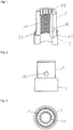
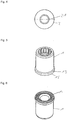
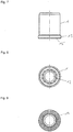
- Andere Weiterbildungen und Ausgestaltungen der Erfindung sind in den übrigen Unteransprüchen angegeben. Ein Ausführungsbeispiel der Erfindung ist in der Zeichnung dargestellt und wird nachfolgend im Einzelnen beschrieben. Es zeigen:
- Fig. 1
- die räumliche Darstellung einer Entkopplungsmutter;
- Fig. 2
- die Darstellung der Entkopplungsmutter aus
Fig. 1 in der Vorderansicht; - Fig. 3
- die Darstellung der Entkopplungsmutter aus
Fig. 1 in der Draufsicht; - Fig. 4
- die Darstellung der Entkopplungsmutter aus
Fig. 1 in der Ansicht von unten; - Fig. 5
- die dreidimensionale Ansicht des Mutternkörpers der Entkopplungsmutter aus
Fig. 1 ; - Fig. 6
- die dreidimensionale Ansicht des Mutternkörpers aus
Fig. 5 in der Ansicht von unten; - Fig. 7
- die Ansicht des Mutternkörpers aus
Fig. 5 in der Ansicht von vorne; - Fig. 8
- der Mutternkörper aus
Fig. 5 in der Draufsicht; - Fig. 9
- der Mutternkörper aus
Fig. 5 in der Ansicht von unten; - Fig. 10
- die dreidimensionale Ansicht der Bördelscheibe der Entkopplungsmutter aus
Fig. 1 ; - Fig. 11
- die Bördelscheibe aus
Fig. 10 in der Ansicht von vorne; - Fig. 12
- die Bördelscheibe aus
Fig. 10 in Schnittdarstellung; - Fig. 13
- die Bördelscheibe aus
Fig. 10 in der Draufsicht und - Fig. 14
- die Bördelscheibe aus
Fig. 10 in der Ansicht von unten. - Die als Ausführungsbeispiel gewählte Befestigungsvorrichtung - nachfolgend "Entkopplungsmutter" genannt - besteht im Wesentlichen aus einem Mutternkörper 1, an dem eine Bördelscheibe 2 unverlierbar gehalten ist.
- Der Mutternkörper 1 ist im Wesentlichen hohlzylindrisch ausgebildet und aus warmfesten Material hergestellt. An seiner Innenwandung ist in den Mutternkörper 1 ein Innengewinde 11 eingebracht, welches an seiner der Scheibe 2 gegenüberliegenden Seite in einen Innenvielkant 12 übergeht. An seinem dem Innenvielkant 12 entgegengesetzten Ende ist an den Mutternkörper 1 umlaufend ein Flansch 13 angeformt, an dessen der Scheibe 2 zugewandten Oberfläche 15 eine Sperrverzahnung 14 eingebracht ist. sind in dem Mutternkörper 1 weiterhin außen umlaufend in regelmäßigen Abständen drei Eindrücke 16 eingebracht, welche der Klemmsicherung des Schraubenkörpers 1 dienen. Im Ausführungsbeispiel ist die Oberfläche 15 des Flansches 13 sowie der Bereich des Innengewindes 11 mit einer Kupferschicht versehen. Die Oberfläche 15 des Flansches 13 ist zudem mit einem trockenen Gleitfilm versehen.
- Die Scheibe 2 ist im Ausführungsbeispiel als Bördelscheibe ausgebildet und aus warmfesten Material hergestellt. Mittig ist in der Bördelscheibe eine Bohrung 21 eingebracht, dessen Durchmesser im Wesentlichen dem Nenndurchmesser des Innengewindes 11 des Mutternkörpers 1 entspricht. An ihrer dem Mutternkörper 1 zugewandten Seite weist die Scheibe 2 eine umlaufende Bördelkante 22 auf. Die an die Bördelkante 22 angrenzende Oberfläche 23 der Bördelscheibe 2 sowie die dieser Oberfläche 23 gegenüberliegende Oberfläche 24 sind im Ausführungsbeispiel mit einer Kupferschicht versehen und zusätzlich mit einem trockenen Gleitfilm beschichtet. Dieser Gleitfilm ist verschieden gegenüber dem auf die Oberfläche 15 des Flansches 13 des Mutternkörpers 1 aufgebrachten Gleitfilm. Dabei weist die Scheibe 2 an ihrer dem Mutternkörper 1 abgewandten Oberfläche 24 einen geringeren Reibwert auf, als die Oberfläche 15 des Flansches 13 des Mutternkörpers 1.
- Die Scheibe 2 ist derart mit dem Mutternkörper 1 verbunden, dass die mit der Sperrverzahnung 14 versehene Oberfläche 15 des Mutternkörpers 1 auf der Oberfläche 23 der Bördelscheibe aufliegt, wobei die Bördelkante 22 um den Flansch 13 gebördelt ist. Damit bilden Mutternkörper 1 und Scheibe 2 eine Einheit, mit hoher Reibung im Innengewinde 11, hoher Reibung zwischen Mutternkörper 1 und Scheibe 2 sowie geringer Reibung zwischen der Scheibe 2 und einem Krümmer. Die Entkopplungsmutter besteht aus nur zwei Einzelteilen, welche jeweils durch Kaltmassiwerformung hergestellt werden können. Die Einzelteile werden unterschiedlich beschichtet und dann unverlierbar zusammengefügt. Dadurch ist eine kostengünstige Serienfertigung dieser Entkopplungsmutter möglich. Eine solche Entkopplungsmutter ist in der Lage, bei einem Anzugsmoment von 16 Nm Vibrationen mit einer Querverschiebung von 2 mm aufzunehmen, ohne die Vorspannkraft vollständig zu verlieren.
Claims (9)
- Vorrichtung zur Befestigung eines Abgaskrümmers an einem Motorblock, umfassend einen Mutternkörper (1), an dem eine Scheibe (2) unverlierbar angeordnet ist, wobei zwischen Mutternkörper (1) und Scheibe (2) Mittel zur Reibwerterhöhung angeordnet sind und wobei die Scheibe (2) an ihrer dem Mutternkörper (1) abgewandten Oberfläche (24) einen geringeren Reibwert aufweist als die der Scheibe (2) zugewandte Oberfläche (15) des Mutternkörpers (1).
- Vorrichtung nach Anspruch 1, dadurch gekennzeichnet, dass die Scheibe (2) an ihrer dem Mutternkörper (1) zugewandten Oberfläche(23) einen Reibwert aufweist, der geringer ist, als der Reibwert der dieser Scheibe (2) zugewandten Oberfläche (15) des Mutternkörpers (1).
- Vorrichtung nach einem der Ansprüche 1 oder 2, dadurch gekennzeichnet,
dass die Scheibe (2) zumindest auf ihrer dem Mutternkörper (24) abgewandten Seite mit einem trockenen Gleitfilm versehen ist. - Vorrichtung nach einem der vorgenannten Ansprüche, dadurch gekennzeichnet, dass der Mutternkörper (1) ein selbstsicherndes Innengewinde (11) aufweist.
- Vorrichtung nach einem der vorgenannten Ansprüche, dadurch gekennzeichnet, dass der Mutternkörper (1) mit einer Klemmsicherung (16) versehen ist.
- Vorrichtung nach einem der vorgenannten Ansprüche, dadurch gekennzeichnet, dass die Scheibe (2) als Bördelscheibe ausgebildet ist und der Mutternkörper (1) an seinem der Scheibe (2) zugewandten Ende einen umlaufenden Flansch (13) aufweist, der von der umlaufenden Bördelkante (22) der Scheibe (2) umschlossen ist.
- Vorrichtung nach einem der vorgenannten Ansprüche, dadurch gekennzeichnet, dass der Mutternkörper (1) an seiner der Scheibe (2) zugewandten Oberfläche (15) mit einer Sperr-Verzahnung (14) versehen ist.
- Vorrichtung nach einem der vorgenannten Ansprüche, dadurch gekennzeichnet, dass die Scheibe (2) mit einer Kupferschicht versehen ist.
- Vorrichtung nach einem der vorgenannten Ansprüche, dadurch gekennzeichnet, dass die Scheibe (2) eine Bohrung (21) aufweist, dessen Durchmesser im Wesentlichen dem Nenndurchmesser des Innengewindes (11) des Mutternkörpers (1) entspricht.
Applications Claiming Priority (1)
| Application Number | Priority Date | Filing Date | Title |
|---|---|---|---|
| DE200910057430 DE102009057430A1 (de) | 2009-12-09 | 2009-12-09 | Befestigungsvorrichtung |
Related Parent Applications (1)
| Application Number | Title | Priority Date | Filing Date |
|---|---|---|---|
| DE102009057430 Previously-Filed-Application | 2009-12-09 |
Publications (3)
| Publication Number | Publication Date |
|---|---|
| EP2333358A2 EP2333358A2 (de) | 2011-06-15 |
| EP2333358A3 EP2333358A3 (de) | 2015-08-05 |
| EP2333358B1 true EP2333358B1 (de) | 2017-03-01 |
Family
ID=43513800
Family Applications (1)
| Application Number | Title | Priority Date | Filing Date |
|---|---|---|---|
| EP10014730.5A Active EP2333358B1 (de) | 2009-12-09 | 2010-11-18 | Befestigungsvorrichtung |
Country Status (3)
| Country | Link |
|---|---|
| EP (1) | EP2333358B1 (de) |
| DE (1) | DE102009057430A1 (de) |
| ES (1) | ES2625482T3 (de) |
Family Cites Families (5)
| Publication number | Priority date | Publication date | Assignee | Title |
|---|---|---|---|---|
| US5190423A (en) * | 1991-02-15 | 1993-03-02 | Ewing Paul E | Locking fastener |
| DE10052915B4 (de) * | 2000-10-25 | 2006-09-14 | Nedschroef Plettenberg Gmbh | Mutter mit einer Klemmsicherung |
| DE10129916A1 (de) * | 2001-06-21 | 2003-01-02 | Porsche Ag | Vorrichtung zur Befestigung eines Abgasturboladers an einem Abgaskrümmer einer Brennkraftmaschine |
| US20040096289A1 (en) * | 2001-08-20 | 2004-05-20 | Theodore Bydalek | Fastener assembly |
| US20070128003A1 (en) * | 2005-12-02 | 2007-06-07 | Song Hong International Co., Ltd. | Combination of a nut and a washer |
-
2009
- 2009-12-09 DE DE200910057430 patent/DE102009057430A1/de not_active Withdrawn
-
2010
- 2010-11-18 EP EP10014730.5A patent/EP2333358B1/de active Active
- 2010-11-18 ES ES10014730.5T patent/ES2625482T3/es active Active
Non-Patent Citations (1)
| Title |
|---|
| None * |
Also Published As
| Publication number | Publication date |
|---|---|
| EP2333358A3 (de) | 2015-08-05 |
| DE102009057430A1 (de) | 2011-06-16 |
| EP2333358A2 (de) | 2011-06-15 |
| ES2625482T3 (es) | 2017-07-19 |
Similar Documents
| Publication | Publication Date | Title |
|---|---|---|
| DE102017122236A1 (de) | Befestigungssystem zur Befestigung eines Bauteils an einem Trägerbauteil | |
| DE19929966A1 (de) | Sicherungssystem für einen Bolzen und eine Mutter | |
| EP2032864B1 (de) | Scheibe und damit versehene schraubenverbindung | |
| EP3565976B1 (de) | Vorrichtung zur drehmomentbegrenzung mit drei stegen | |
| EP3032093B1 (de) | Befestigungsvorrichtung zur befestigung eines rotorblattes an einer rotornabe einer windkraftanlage | |
| DE69702395T2 (de) | System zum sperren einer relativen bewegung zwischen zwei körpern, in zumindest einem sinn einer vorgegebenen richtung | |
| DE102016209846A1 (de) | Keilsicherungsmutteranordnung | |
| WO2001038747A1 (de) | Mutter mit druckring | |
| EP2729680B1 (de) | Verbrennungsmotor mit zylinderkopf sowie verfahren zum festlegen eines abgaskrümmers an einem zylinderkopf | |
| DE102008022936B4 (de) | Radbefestigungsvorrichtung | |
| DE10109660B4 (de) | Sicherungsring und Befestigungsvorrichtung für eine Welle-Nabe-Verbindung | |
| EP2230410B1 (de) | Befestigungselement | |
| DE102015209641A1 (de) | Schraubverbindung und Läufer für einen Abgasturbolader | |
| EP2333358A2 (de) | Befestigungsvorrichtung | |
| EP1785636A2 (de) | Schraubensicherung | |
| EP3705739B1 (de) | Schutzkappe für gewindebolzen | |
| DE102010061553B4 (de) | Befestigungselement für einen Schwingungstilger mit einer ringförmigen Tilgermasse | |
| EP2798231B1 (de) | Abstandselement und Verfahren zur Vor- und Endmontage | |
| DE102004025934B4 (de) | Geteilter Pleuel mit verschraubtem Pleueldeckel | |
| DE102020116616A1 (de) | Schraube | |
| WO2017054946A1 (de) | Vorrichtung zur kontrolle von schraubverbindungen | |
| DE102010018345A1 (de) | Baugruppe zur Befestigung eines Abgaskrümmers an einem Zylinderkopf sowie Motoreinheit | |
| DE19905706C2 (de) | Kombimutter mit schräger Unterlegscheibe | |
| EP0989311A1 (de) | Verschraubungsteil | |
| DE102013112974A1 (de) | Sandwichblechkonstruktion |
Legal Events
| Date | Code | Title | Description |
|---|---|---|---|
| PUAI | Public reference made under article 153(3) epc to a published international application that has entered the european phase |
Free format text: ORIGINAL CODE: 0009012 |
|
| AK | Designated contracting states |
Kind code of ref document: A2 Designated state(s): AL AT BE BG CH CY CZ DE DK EE ES FI FR GB GR HR HU IE IS IT LI LT LU LV MC MK MT NL NO PL PT RO RS SE SI SK SM TR |
|
| AX | Request for extension of the european patent |
Extension state: BA ME |
|
| PUAL | Search report despatched |
Free format text: ORIGINAL CODE: 0009013 |
|
| AK | Designated contracting states |
Kind code of ref document: A3 Designated state(s): AL AT BE BG CH CY CZ DE DK EE ES FI FR GB GR HR HU IE IS IT LI LT LU LV MC MK MT NL NO PL PT RO RS SE SI SK SM TR |
|
| AX | Request for extension of the european patent |
Extension state: BA ME |
|
| RIC1 | Information provided on ipc code assigned before grant |
Ipc: F16B 33/06 20060101ALN20150701BHEP Ipc: F16B 41/00 20060101ALN20150701BHEP Ipc: F16B 39/282 20060101AFI20150701BHEP |
|
| 17P | Request for examination filed |
Effective date: 20160127 |
|
| RBV | Designated contracting states (corrected) |
Designated state(s): AL AT BE BG CH CY CZ DE DK EE ES FI FR GB GR HR HU IE IS IT LI LT LU LV MC MK MT NL NO PL PT RO RS SE SI SK SM TR |
|
| REG | Reference to a national code |
Ref country code: DE Ref legal event code: R079 Ref document number: 502010013224 Country of ref document: DE Free format text: PREVIOUS MAIN CLASS: F16B0037000000 Ipc: F16B0039282000 |
|
| GRAP | Despatch of communication of intention to grant a patent |
Free format text: ORIGINAL CODE: EPIDOSNIGR1 |
|
| RIC1 | Information provided on ipc code assigned before grant |
Ipc: F16B 39/282 20060101AFI20161102BHEP Ipc: F16B 33/06 20060101ALN20161102BHEP Ipc: F16B 41/00 20060101ALN20161102BHEP |
|
| INTG | Intention to grant announced |
Effective date: 20161117 |
|
| GRAS | Grant fee paid |
Free format text: ORIGINAL CODE: EPIDOSNIGR3 |
|
| GRAA | (expected) grant |
Free format text: ORIGINAL CODE: 0009210 |
|
| AK | Designated contracting states |
Kind code of ref document: B1 Designated state(s): AL AT BE BG CH CY CZ DE DK EE ES FI FR GB GR HR HU IE IS IT LI LT LU LV MC MK MT NL NO PL PT RO RS SE SI SK SM TR |
|
| REG | Reference to a national code |
Ref country code: GB Ref legal event code: FG4D Free format text: NOT ENGLISH |
|
| REG | Reference to a national code |
Ref country code: CH Ref legal event code: EP Ref country code: AT Ref legal event code: REF Ref document number: 871734 Country of ref document: AT Kind code of ref document: T Effective date: 20170315 |
|
| REG | Reference to a national code |
Ref country code: IE Ref legal event code: FG4D Free format text: LANGUAGE OF EP DOCUMENT: GERMAN |
|
| REG | Reference to a national code |
Ref country code: DE Ref legal event code: R096 Ref document number: 502010013224 Country of ref document: DE |
|
| REG | Reference to a national code |
Ref country code: SE Ref legal event code: TRGR |
|
| REG | Reference to a national code |
Ref country code: NL Ref legal event code: MP Effective date: 20170301 |
|
| REG | Reference to a national code |
Ref country code: LT Ref legal event code: MG4D |
|
| REG | Reference to a national code |
Ref country code: ES Ref legal event code: FG2A Ref document number: 2625482 Country of ref document: ES Kind code of ref document: T3 Effective date: 20170719 |
|
| PG25 | Lapsed in a contracting state [announced via postgrant information from national office to epo] |
Ref country code: GR Free format text: LAPSE BECAUSE OF FAILURE TO SUBMIT A TRANSLATION OF THE DESCRIPTION OR TO PAY THE FEE WITHIN THE PRESCRIBED TIME-LIMIT Effective date: 20170602 Ref country code: HR Free format text: LAPSE BECAUSE OF FAILURE TO SUBMIT A TRANSLATION OF THE DESCRIPTION OR TO PAY THE FEE WITHIN THE PRESCRIBED TIME-LIMIT Effective date: 20170301 Ref country code: LT Free format text: LAPSE BECAUSE OF FAILURE TO SUBMIT A TRANSLATION OF THE DESCRIPTION OR TO PAY THE FEE WITHIN THE PRESCRIBED TIME-LIMIT Effective date: 20170301 Ref country code: NO Free format text: LAPSE BECAUSE OF FAILURE TO SUBMIT A TRANSLATION OF THE DESCRIPTION OR TO PAY THE FEE WITHIN THE PRESCRIBED TIME-LIMIT Effective date: 20170601 Ref country code: FI Free format text: LAPSE BECAUSE OF FAILURE TO SUBMIT A TRANSLATION OF THE DESCRIPTION OR TO PAY THE FEE WITHIN THE PRESCRIBED TIME-LIMIT Effective date: 20170301 |
|
| PG25 | Lapsed in a contracting state [announced via postgrant information from national office to epo] |
Ref country code: LV Free format text: LAPSE BECAUSE OF FAILURE TO SUBMIT A TRANSLATION OF THE DESCRIPTION OR TO PAY THE FEE WITHIN THE PRESCRIBED TIME-LIMIT Effective date: 20170301 Ref country code: BG Free format text: LAPSE BECAUSE OF FAILURE TO SUBMIT A TRANSLATION OF THE DESCRIPTION OR TO PAY THE FEE WITHIN THE PRESCRIBED TIME-LIMIT Effective date: 20170601 Ref country code: RS Free format text: LAPSE BECAUSE OF FAILURE TO SUBMIT A TRANSLATION OF THE DESCRIPTION OR TO PAY THE FEE WITHIN THE PRESCRIBED TIME-LIMIT Effective date: 20170301 |
|
| PG25 | Lapsed in a contracting state [announced via postgrant information from national office to epo] |
Ref country code: NL Free format text: LAPSE BECAUSE OF FAILURE TO SUBMIT A TRANSLATION OF THE DESCRIPTION OR TO PAY THE FEE WITHIN THE PRESCRIBED TIME-LIMIT Effective date: 20170301 |
|
| PG25 | Lapsed in a contracting state [announced via postgrant information from national office to epo] |
Ref country code: EE Free format text: LAPSE BECAUSE OF FAILURE TO SUBMIT A TRANSLATION OF THE DESCRIPTION OR TO PAY THE FEE WITHIN THE PRESCRIBED TIME-LIMIT Effective date: 20170301 Ref country code: CZ Free format text: LAPSE BECAUSE OF FAILURE TO SUBMIT A TRANSLATION OF THE DESCRIPTION OR TO PAY THE FEE WITHIN THE PRESCRIBED TIME-LIMIT Effective date: 20170301 Ref country code: SK Free format text: LAPSE BECAUSE OF FAILURE TO SUBMIT A TRANSLATION OF THE DESCRIPTION OR TO PAY THE FEE WITHIN THE PRESCRIBED TIME-LIMIT Effective date: 20170301 Ref country code: RO Free format text: LAPSE BECAUSE OF FAILURE TO SUBMIT A TRANSLATION OF THE DESCRIPTION OR TO PAY THE FEE WITHIN THE PRESCRIBED TIME-LIMIT Effective date: 20170301 |
|
| REG | Reference to a national code |
Ref country code: FR Ref legal event code: PLFP Year of fee payment: 8 |
|
| PG25 | Lapsed in a contracting state [announced via postgrant information from national office to epo] |
Ref country code: PL Free format text: LAPSE BECAUSE OF FAILURE TO SUBMIT A TRANSLATION OF THE DESCRIPTION OR TO PAY THE FEE WITHIN THE PRESCRIBED TIME-LIMIT Effective date: 20170301 Ref country code: SM Free format text: LAPSE BECAUSE OF FAILURE TO SUBMIT A TRANSLATION OF THE DESCRIPTION OR TO PAY THE FEE WITHIN THE PRESCRIBED TIME-LIMIT Effective date: 20170301 Ref country code: PT Free format text: LAPSE BECAUSE OF FAILURE TO SUBMIT A TRANSLATION OF THE DESCRIPTION OR TO PAY THE FEE WITHIN THE PRESCRIBED TIME-LIMIT Effective date: 20170703 Ref country code: IS Free format text: LAPSE BECAUSE OF FAILURE TO SUBMIT A TRANSLATION OF THE DESCRIPTION OR TO PAY THE FEE WITHIN THE PRESCRIBED TIME-LIMIT Effective date: 20170701 |
|
| REG | Reference to a national code |
Ref country code: DE Ref legal event code: R097 Ref document number: 502010013224 Country of ref document: DE |
|
| PLBE | No opposition filed within time limit |
Free format text: ORIGINAL CODE: 0009261 |
|
| STAA | Information on the status of an ep patent application or granted ep patent |
Free format text: STATUS: NO OPPOSITION FILED WITHIN TIME LIMIT |
|
| PG25 | Lapsed in a contracting state [announced via postgrant information from national office to epo] |
Ref country code: DK Free format text: LAPSE BECAUSE OF FAILURE TO SUBMIT A TRANSLATION OF THE DESCRIPTION OR TO PAY THE FEE WITHIN THE PRESCRIBED TIME-LIMIT Effective date: 20170301 |
|
| 26N | No opposition filed |
Effective date: 20171204 |
|
| PG25 | Lapsed in a contracting state [announced via postgrant information from national office to epo] |
Ref country code: SI Free format text: LAPSE BECAUSE OF FAILURE TO SUBMIT A TRANSLATION OF THE DESCRIPTION OR TO PAY THE FEE WITHIN THE PRESCRIBED TIME-LIMIT Effective date: 20170301 |
|
| PG25 | Lapsed in a contracting state [announced via postgrant information from national office to epo] |
Ref country code: MC Free format text: LAPSE BECAUSE OF FAILURE TO SUBMIT A TRANSLATION OF THE DESCRIPTION OR TO PAY THE FEE WITHIN THE PRESCRIBED TIME-LIMIT Effective date: 20170301 |
|
| GBPC | Gb: european patent ceased through non-payment of renewal fee |
Effective date: 20171118 |
|
| PG25 | Lapsed in a contracting state [announced via postgrant information from national office to epo] |
Ref country code: CH Free format text: LAPSE BECAUSE OF NON-PAYMENT OF DUE FEES Effective date: 20171130 Ref country code: LI Free format text: LAPSE BECAUSE OF NON-PAYMENT OF DUE FEES Effective date: 20171130 |
|
| PG25 | Lapsed in a contracting state [announced via postgrant information from national office to epo] |
Ref country code: LU Free format text: LAPSE BECAUSE OF NON-PAYMENT OF DUE FEES Effective date: 20171118 |
|
| REG | Reference to a national code |
Ref country code: BE Ref legal event code: MM Effective date: 20171130 |
|
| REG | Reference to a national code |
Ref country code: IE Ref legal event code: MM4A |
|
| PG25 | Lapsed in a contracting state [announced via postgrant information from national office to epo] |
Ref country code: MT Free format text: LAPSE BECAUSE OF FAILURE TO SUBMIT A TRANSLATION OF THE DESCRIPTION OR TO PAY THE FEE WITHIN THE PRESCRIBED TIME-LIMIT Effective date: 20170301 |
|
| PG25 | Lapsed in a contracting state [announced via postgrant information from national office to epo] |
Ref country code: IE Free format text: LAPSE BECAUSE OF NON-PAYMENT OF DUE FEES Effective date: 20171118 |
|
| PG25 | Lapsed in a contracting state [announced via postgrant information from national office to epo] |
Ref country code: GB Free format text: LAPSE BECAUSE OF NON-PAYMENT OF DUE FEES Effective date: 20171118 Ref country code: BE Free format text: LAPSE BECAUSE OF NON-PAYMENT OF DUE FEES Effective date: 20171130 |
|
| REG | Reference to a national code |
Ref country code: AT Ref legal event code: MM01 Ref document number: 871734 Country of ref document: AT Kind code of ref document: T Effective date: 20171118 |
|
| PG25 | Lapsed in a contracting state [announced via postgrant information from national office to epo] |
Ref country code: AT Free format text: LAPSE BECAUSE OF NON-PAYMENT OF DUE FEES Effective date: 20171118 |
|
| PG25 | Lapsed in a contracting state [announced via postgrant information from national office to epo] |
Ref country code: HU Free format text: LAPSE BECAUSE OF FAILURE TO SUBMIT A TRANSLATION OF THE DESCRIPTION OR TO PAY THE FEE WITHIN THE PRESCRIBED TIME-LIMIT; INVALID AB INITIO Effective date: 20101118 |
|
| PG25 | Lapsed in a contracting state [announced via postgrant information from national office to epo] |
Ref country code: CY Free format text: LAPSE BECAUSE OF NON-PAYMENT OF DUE FEES Effective date: 20170301 |
|
| PG25 | Lapsed in a contracting state [announced via postgrant information from national office to epo] |
Ref country code: MK Free format text: LAPSE BECAUSE OF FAILURE TO SUBMIT A TRANSLATION OF THE DESCRIPTION OR TO PAY THE FEE WITHIN THE PRESCRIBED TIME-LIMIT Effective date: 20170301 |
|
| PG25 | Lapsed in a contracting state [announced via postgrant information from national office to epo] |
Ref country code: TR Free format text: LAPSE BECAUSE OF FAILURE TO SUBMIT A TRANSLATION OF THE DESCRIPTION OR TO PAY THE FEE WITHIN THE PRESCRIBED TIME-LIMIT Effective date: 20170301 |
|
| PG25 | Lapsed in a contracting state [announced via postgrant information from national office to epo] |
Ref country code: AL Free format text: LAPSE BECAUSE OF FAILURE TO SUBMIT A TRANSLATION OF THE DESCRIPTION OR TO PAY THE FEE WITHIN THE PRESCRIBED TIME-LIMIT Effective date: 20170301 |
|
| PGFP | Annual fee paid to national office [announced via postgrant information from national office to epo] |
Ref country code: DE Payment date: 20251107 Year of fee payment: 16 |
|
| PGFP | Annual fee paid to national office [announced via postgrant information from national office to epo] |
Ref country code: IT Payment date: 20251128 Year of fee payment: 16 |
|
| PGFP | Annual fee paid to national office [announced via postgrant information from national office to epo] |
Ref country code: FR Payment date: 20251125 Year of fee payment: 16 |
|
| PGFP | Annual fee paid to national office [announced via postgrant information from national office to epo] |
Ref country code: SE Payment date: 20251119 Year of fee payment: 16 |
|
| PGFP | Annual fee paid to national office [announced via postgrant information from national office to epo] |
Ref country code: ES Payment date: 20251216 Year of fee payment: 16 |