EP2333334A2 - Actuating apparatus - Google Patents
Actuating apparatus Download PDFInfo
- Publication number
- EP2333334A2 EP2333334A2 EP10192738A EP10192738A EP2333334A2 EP 2333334 A2 EP2333334 A2 EP 2333334A2 EP 10192738 A EP10192738 A EP 10192738A EP 10192738 A EP10192738 A EP 10192738A EP 2333334 A2 EP2333334 A2 EP 2333334A2
- Authority
- EP
- European Patent Office
- Prior art keywords
- actuator
- resilient member
- elongate
- actuating apparatus
- configuration
- Prior art date
- Legal status (The legal status is an assumption and is not a legal conclusion. Google has not performed a legal analysis and makes no representation as to the accuracy of the status listed.)
- Withdrawn
Links
Images


Classifications
-
- F—MECHANICAL ENGINEERING; LIGHTING; HEATING; WEAPONS; BLASTING
- F03—MACHINES OR ENGINES FOR LIQUIDS; WIND, SPRING, OR WEIGHT MOTORS; PRODUCING MECHANICAL POWER OR A REACTIVE PROPULSIVE THRUST, NOT OTHERWISE PROVIDED FOR
- F03G—SPRING, WEIGHT, INERTIA OR LIKE MOTORS; MECHANICAL-POWER PRODUCING DEVICES OR MECHANISMS, NOT OTHERWISE PROVIDED FOR OR USING ENERGY SOURCES NOT OTHERWISE PROVIDED FOR
- F03G7/00—Mechanical-power-producing mechanisms, not otherwise provided for or using energy sources not otherwise provided for
- F03G7/06—Mechanical-power-producing mechanisms, not otherwise provided for or using energy sources not otherwise provided for using expansion or contraction of bodies due to heating, cooling, moistening, drying or the like
- F03G7/061—Mechanical-power-producing mechanisms, not otherwise provided for or using energy sources not otherwise provided for using expansion or contraction of bodies due to heating, cooling, moistening, drying or the like characterised by the actuating element
- F03G7/0614—Mechanical-power-producing mechanisms, not otherwise provided for or using energy sources not otherwise provided for using expansion or contraction of bodies due to heating, cooling, moistening, drying or the like characterised by the actuating element using shape memory elements
-
- F—MECHANICAL ENGINEERING; LIGHTING; HEATING; WEAPONS; BLASTING
- F03—MACHINES OR ENGINES FOR LIQUIDS; WIND, SPRING, OR WEIGHT MOTORS; PRODUCING MECHANICAL POWER OR A REACTIVE PROPULSIVE THRUST, NOT OTHERWISE PROVIDED FOR
- F03G—SPRING, WEIGHT, INERTIA OR LIKE MOTORS; MECHANICAL-POWER PRODUCING DEVICES OR MECHANISMS, NOT OTHERWISE PROVIDED FOR OR USING ENERGY SOURCES NOT OTHERWISE PROVIDED FOR
- F03G7/00—Mechanical-power-producing mechanisms, not otherwise provided for or using energy sources not otherwise provided for
- F03G7/06—Mechanical-power-producing mechanisms, not otherwise provided for or using energy sources not otherwise provided for using expansion or contraction of bodies due to heating, cooling, moistening, drying or the like
- F03G7/061—Mechanical-power-producing mechanisms, not otherwise provided for or using energy sources not otherwise provided for using expansion or contraction of bodies due to heating, cooling, moistening, drying or the like characterised by the actuating element
- F03G7/0614—Mechanical-power-producing mechanisms, not otherwise provided for or using energy sources not otherwise provided for using expansion or contraction of bodies due to heating, cooling, moistening, drying or the like characterised by the actuating element using shape memory elements
- F03G7/06143—Wires
-
- F—MECHANICAL ENGINEERING; LIGHTING; HEATING; WEAPONS; BLASTING
- F03—MACHINES OR ENGINES FOR LIQUIDS; WIND, SPRING, OR WEIGHT MOTORS; PRODUCING MECHANICAL POWER OR A REACTIVE PROPULSIVE THRUST, NOT OTHERWISE PROVIDED FOR
- F03G—SPRING, WEIGHT, INERTIA OR LIKE MOTORS; MECHANICAL-POWER PRODUCING DEVICES OR MECHANISMS, NOT OTHERWISE PROVIDED FOR OR USING ENERGY SOURCES NOT OTHERWISE PROVIDED FOR
- F03G7/00—Mechanical-power-producing mechanisms, not otherwise provided for or using energy sources not otherwise provided for
- F03G7/06—Mechanical-power-producing mechanisms, not otherwise provided for or using energy sources not otherwise provided for using expansion or contraction of bodies due to heating, cooling, moistening, drying or the like
- F03G7/062—Mechanical-power-producing mechanisms, not otherwise provided for or using energy sources not otherwise provided for using expansion or contraction of bodies due to heating, cooling, moistening, drying or the like characterised by the activation arrangement
-
- F—MECHANICAL ENGINEERING; LIGHTING; HEATING; WEAPONS; BLASTING
- F03—MACHINES OR ENGINES FOR LIQUIDS; WIND, SPRING, OR WEIGHT MOTORS; PRODUCING MECHANICAL POWER OR A REACTIVE PROPULSIVE THRUST, NOT OTHERWISE PROVIDED FOR
- F03G—SPRING, WEIGHT, INERTIA OR LIKE MOTORS; MECHANICAL-POWER PRODUCING DEVICES OR MECHANISMS, NOT OTHERWISE PROVIDED FOR OR USING ENERGY SOURCES NOT OTHERWISE PROVIDED FOR
- F03G7/00—Mechanical-power-producing mechanisms, not otherwise provided for or using energy sources not otherwise provided for
- F03G7/06—Mechanical-power-producing mechanisms, not otherwise provided for or using energy sources not otherwise provided for using expansion or contraction of bodies due to heating, cooling, moistening, drying or the like
- F03G7/061—Mechanical-power-producing mechanisms, not otherwise provided for or using energy sources not otherwise provided for using expansion or contraction of bodies due to heating, cooling, moistening, drying or the like characterised by the actuating element
- F03G7/0614—Mechanical-power-producing mechanisms, not otherwise provided for or using energy sources not otherwise provided for using expansion or contraction of bodies due to heating, cooling, moistening, drying or the like characterised by the actuating element using shape memory elements
- F03G7/06146—Torque tubes or torsion bars
Definitions
- the present invention relates to an actuating apparatus which may, for example, be arranged to provide an actuating rotation or force on demand.
- Actuators are used in many technical fields, such as in the aerospace, energy, automotive and healthcare industries to provide an actuating force.
- actuators are used for deployment of flight control surfaces on aircraft, the opening and closing of aerodynamic covers, hatches and doorways, control of the pitch of blades on wind turbines and tidal generators and actuators for supplying fluids etc.
- actuators typically comprise an assembly of discrete mechanical parts such as shafts, gearboxes, bearings, hinges, motors and locking mechanisms which are typically made from dense metallic components and so are heavy and require regular maintenance and inspection.
- such actuators require a drive to provide actuation such as a hydraulic actuator which typically requires complex arrangements of piping and as well as taking up often valuable space are often expensive and may suffer from problems such as leakage.
- an actuating apparatus comprising: a resilient member having a plurality of co-acting elements arranged to move relative to each other, the member being arrangeable in a first configuration and a second con figuration and an actuator secured to the resilient member at at least two points, wherein the actuator is arranged to force the resilient member into one of or between the two configurations.
- examples of the present invention provide a lightweight, compact and robust actuating apparatus.
- the resilient member is preferably arranged to twist along its axial length when acted upon by the actuator.
- the resilient member preferably comprises a plurality of load bearing elongate rods secured at each end in a mount such that the end mounts are able to rotate relative to each other supported by flexing of the elongate rods.
- Such an arrangement substantially inhibits axial bending and buckling whilst allowing for large rotational deformations.
- the plurality of elongate elements may be embedded within a matrix, such as a polymer matrix or an elastomeric matrix to allow for large torsional rotations when in a first, relatively soft state and can maintain or "lock" the shape of the member when in a second relatively hard state, typically by being cooled or allowed to cool to a lower temperature.
- the actuator may be wound around the resilient member to provide rotational actuation.
- the actuator may be elongate and the rotational actuation may be controlled by varying the length of the actuator. For example by contraction of the length of the elongate actuator, for example by the actuator being made from shape memory alloy which contracts during a phase transition, the resilient member may be twisted along its length.
- the actuator may be lengthened, for example by heating a wire or strip which may be metallic to allow release of a pre-twisted resilient member.
- an actuating apparatus 1 comprising a resilient member 10 and an actuator 20 secured to the resilient member at two points 21, 22.
- the resilient member 10 is arrangeable in or between first and second configurations under control of the actuator 20.
- the actuator 20 is elongate and arranged to twist the resilient member 10 along its axis 23 by the actuator being arranged to be shortened or lengthened and wrapped around the resilient member 10 and secured at two distal points 21, 22.
- the resilient member could be arranged to undergo other types of distortion apart from twisting or rotation, such as contracting and stretching or bending about its axis for example.
- the length of the actuator 20 is arranged to be variable to distort the resilient member 10 to a desired extent.
- the actuator 20 may comprise a length of shape memory alloy which undergoes axial contraction when actuated. Any suitable shape memory alloy may be used as is known in the art, such as for example nickel-titanium, copper-aluminium-nickel, copper-zinc-aluminium and iron-manganese-silicon alloys for example.
- the length of the actuator 20 may be arranged to contract upon actuation to cause the twisting of the flexible member.
- the actuator 20 may be arranged to lengthen upon actuation to allow a pre-twisted resilient member 10 to twist back to its original configuration upon actuation.
- the actuator 20 could be made from any suitable material.
- shape memory alloys provide a practical change in length for a relatively small change in temperature which may be easily controlled, for example by passing an electric current therethrough.
- the actuator 20 being a single elongate length or wire as shown in Figure 1 , it could also take the form of a plurality of elongate lengths or wires or a web of interconnected elongate lengths or wires which could have the same or different widths and lengths.
- Figure 2 shows a further example of the present invention in which the actuator 20 has been wrapped around the flexible member 10 at a different winding angle to provide a desired, greater level of twisting within the flexible member 10 for a given change in length of the elongate actuator 20.
- any desired winding angle may be used to provide a desired level of twisting of the elongate member 10 for any particular application.
- the appropriate winding configuration will depend upon the particular application and geometry of the flexible member. For example, a short member with a large diameter may only require a 1 ⁇ 4 turn to achieve a suitable twist.
- the actuator may be wrapped once or several times around the resilient member 10.
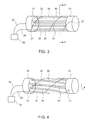
- FIG. 3 shows a perspective view of a more detailed example of the present invention.
- the flexible member 10 is provided by a plurality of elongate elements or rods 30 which are secured at each end in mounts 31.
- the elongate rods 30 are preferably relatively stiff to provide a highly anisotropic flexible member 10 which has low torsional rigidity and is resistant to axial bending.
- the elongate rods may, for example, comprise pultruded fibre reinforced polymer composite rods which are resistant to axial bending due to their high flexural and compressive stiffness properties.
- One end of the actuator 21 is secured to one of the mounts 31 and the other end of the actuator 22 is secured to the other mount 31.
- the length of the actuator 20 contracts rotating one mount 31 relative to the other, twisting the flexible member 10.
- the axial stiffness of the beam produced by the elongate rods 30 enables rotation when actuated with little compressive strain making it very suitable for many applications, such as for a load bearing actuator.
- each mount 31 may be secured to a suitable structure to provide a desired effect, such as deployment of flight control surfaces on an aircraft, opening and closing of aerodynamic covers, hatches and doorways, control of the pitch of a blade on a wind turbine or actuation of a tap or valve for example.
- the elongate rods 30 may be provided in a flexible matrix 40 provided between the mounts 31 and surrounding at least a portion of some of the elongate rods 30.
- the flexible matrix 40 is controlled to be in either relatively soft or hard forms, typically by heating or cooling above or below its specific temperature.
- the matrix 40 is in its relatively low stiffness or soft form, typically by being heated, to allow distortion of the resilient member 10 and when the resilient member has been distorted to its desired extent the matrix 40 may be allowed to harden, for example by turning "off” the heat supplied to it so that the matrix hardens and "locks" the elongate rods 30 and the flexible member 10 in the desired actuated configuration.
- the matrix 40 may be heated to soften it so that the resilience of the rods 30 in the mounts 31 returns the flexible member 10 back to its original non-twisted configuration.
- the matrix 40 may be heated and/or cooled by any suitable means. For example, heating may be provided by the actuator 20 to soften it during actuation or a separate heater 41 may be provided within the matrix to provide heating at appropriate times, typically upon actuation.
- the resilient member 10 may be provided in a fluid such as water and the fluid may be heated or cooled to soften or harden the matrix 40 appropriately. Deformed shapes can be maintained without constant actuation when the matrix 40 is cooled below its specific temperature to temporarily "lock" the resilient member 10 in the deformed state.
- Figure 3 also shows a controller 50, such as a microprocessor or computer for example.
- the controller 50 may provide a control signal or current 24 to the actuator 20 to control the variation in its length.
- the controller 50 may also provide a control signal or current 42 to the heater 41 to heat the matrix 40.
- the matrix material may be selected such that it will cool to its "locked" or relatively hard state when not being heated by heater 41.
- Figure 4 shows the resilient member 10 of Figure 3 with the actuator 20 having twisted the resilient member 10.
- the elongate rods 30 have flexed to accommodate the relative rotation of the mounts 31 under the action of the actuator 20.
- the actuator 20 has contracted to force the mounts 31 to rotate relative to each other.
- the matrix 40 will have been heated by the heater 41 to soften it before and/or during actuation and the resilient member 10 may be "locked” in the flexed configuration shown in Figure 4 by allowing the matrix 40 to harden, typically by turning “off” the heater 41 and allowing the matrix 40 to cool.
- power to the actuator 20 may be turned off saving energy.
- the matrix 40 may be softened, for example by heating, and the resilience of the elongate rods 30 will return the flexible member 10 to the configuration shown in Figure 3 .
- the "locking" action of the matrix 40 and the flexibility of the elongate member 10 enables the actuator 20 to only have to be actuated once while the matrix 40 is soft to change from one configuration to another and then be locked in that second configuration by hardening of the matrix 40.
- the matrix 40 is heated and the resilience of the elongate rods 30 returns the flexible member 10 to its previous configuration without having to use the actuator 20.
- Figure 5 is a cross-sectional view from lines 5-5 of Figure 3 showing the inner side of the mount 31.
- six substantially equiangularly spaced elongate rods 30 are shown.
- any number of one or more elongate rods 30 may be used in the flexible member 10.
- a length of electrical heating wire 41 is shown passing through the axial centre of the mount 31 to heat the matrix 40 during twisting of the flexible member 10.
- the point 22 at which the elongate actuator 20 is secured to the mount 31 is also shown.
- the elongate actuator 20 may be secured to the mount 31 in any suitable way, such as by a screw, welding, gluing, crimping or attaching to a bracket provided on the mount 31.
- An example of an actuating apparatus has been constructed comprising carbon fibre reinforced epoxy rods 30 of 1.7 mm diameter, embedded in silicone elastomer matrix 40 with the composite resilient beam 10 dimensions of 17.5 mm diameter and 110 mm length.
- Two prestrained (approximately 2%) 0.375 mm nickel-titanium SMA (shape memory alloy) wires were contained within silicone tubing to prevent damage to the matrix 40 when actuated and externally wound on to the composite beam 10.
- Various winding angles of about 25° to 50° to the axis were tested with 1, 1.5, 2 and 2.5 turns.
- Aluminium plate end tabs were bonded to slots on each end of the beam 10 and the SMA wires were attached with machine screws at one end and crimps at the other.
- the distance between the SMA wire mounting points was 150 mm.
- a twist of above 25° was achieved at the equivalent of 90° per minute with no blocking load applied during initial trials and with no apparent beam deflection during rotation.
- Altering the number and winding angle of the actuator length 20 was found to alter the achievable torque and rotation which could be adapted to any suitable application.
- Examples of the present invention have been found to provide a lightweight, compact, and robust actuating apparatus as explained above. Many variations may be made to the example described above while still falling within the scope of the invention.
- any number of elongate actuators 20 may be used with any appropriate configuration or winding angle.
- Any suitable number of elongate rods 30 may be incorporated into the resilient member or rod 10 and any suitable materials may be used for the appropriate parts.
- the resilience of the member 10 may be provided by any suitable means such as by the flexibility of composite rods 30 and/or by the flexibility of the joint between the rods 30 and the mounts 31.
Landscapes
- Engineering & Computer Science (AREA)
- Chemical & Material Sciences (AREA)
- Combustion & Propulsion (AREA)
- Mechanical Engineering (AREA)
- General Engineering & Computer Science (AREA)
- Actuator (AREA)
- Transmission Devices (AREA)
- Power-Operated Mechanisms For Wings (AREA)
- Springs (AREA)
Abstract
Description
- The present invention relates to an actuating apparatus which may, for example, be arranged to provide an actuating rotation or force on demand.
- Actuators are used in many technical fields, such as in the aerospace, energy, automotive and healthcare industries to provide an actuating force. For example, actuators are used for deployment of flight control surfaces on aircraft, the opening and closing of aerodynamic covers, hatches and doorways, control of the pitch of blades on wind turbines and tidal generators and actuators for supplying fluids etc. However, actuators typically comprise an assembly of discrete mechanical parts such as shafts, gearboxes, bearings, hinges, motors and locking mechanisms which are typically made from dense metallic components and so are heavy and require regular maintenance and inspection. Furthermore, such actuators require a drive to provide actuation such as a hydraulic actuator which typically requires complex arrangements of piping and as well as taking up often valuable space are often expensive and may suffer from problems such as leakage.
- It would be desirable to provide an actuating apparatus which alleviates at least some of the problems of the prior art.
- According to the present invention there is provided an actuating apparatus comprising: a resilient member having a plurality of co-acting elements arranged to move relative to each other, the member being arrangeable in a first configuration and a second con figuration and an actuator secured to the resilient member at at least two points, wherein the actuator is arranged to force the resilient member into one of or between the two configurations.
- As the actuating apparatus includes a resilient member which is acted upon by the actuator, examples of the present invention provide a lightweight, compact and robust actuating apparatus.
- The resilient member is preferably arranged to twist along its axial length when acted upon by the actuator. The resilient member preferably comprises a plurality of load bearing elongate rods secured at each end in a mount such that the end mounts are able to rotate relative to each other supported by flexing of the elongate rods. Such an arrangement substantially inhibits axial bending and buckling whilst allowing for large rotational deformations. The plurality of elongate elements may be embedded within a matrix, such as a polymer matrix or an elastomeric matrix to allow for large torsional rotations when in a first, relatively soft state and can maintain or "lock" the shape of the member when in a second relatively hard state, typically by being cooled or allowed to cool to a lower temperature.
- The actuator may be wound around the resilient member to provide rotational actuation. The actuator may be elongate and the rotational actuation may be controlled by varying the length of the actuator. For example by contraction of the length of the elongate actuator, for example by the actuator being made from shape memory alloy which contracts during a phase transition, the resilient member may be twisted along its length. Alternatively, the actuator may be lengthened, for example by heating a wire or strip which may be metallic to allow release of a pre-twisted resilient member.
- Embodiments of the present invention will now be described, by way of example only, with reference to the accompanying drawings, in which:
-
Figure 1 shows a first example of the present invention; -
Figure 2 shows a second example of the present invention; -
Figure 3 is a perspective view of a more detailed example of the present invention; -
Figure 4 shows the example ofFigure 3 with the resilient member in a twisted configuration; and -
Figure 5 is an end view of one of the mounts shown inFigures 3 and 4 . - As shown in
Figure 1 there is provided anactuating apparatus 1 comprising aresilient member 10 and anactuator 20 secured to the resilient member at twopoints resilient member 10 is arrangeable in or between first and second configurations under control of theactuator 20. - In this example the
actuator 20 is elongate and arranged to twist theresilient member 10 along itsaxis 23 by the actuator being arranged to be shortened or lengthened and wrapped around theresilient member 10 and secured at twodistal points - In this example, the length of the
actuator 20 is arranged to be variable to distort theresilient member 10 to a desired extent. Theactuator 20 may comprise a length of shape memory alloy which undergoes axial contraction when actuated. Any suitable shape memory alloy may be used as is known in the art, such as for example nickel-titanium, copper-aluminium-nickel, copper-zinc-aluminium and iron-manganese-silicon alloys for example. The length of theactuator 20 may be arranged to contract upon actuation to cause the twisting of the flexible member. Alternatively, theactuator 20 may be arranged to lengthen upon actuation to allow a pre-twistedresilient member 10 to twist back to its original configuration upon actuation. Theactuator 20 could be made from any suitable material. However, it has been found that shape memory alloys provide a practical change in length for a relatively small change in temperature which may be easily controlled, for example by passing an electric current therethrough. As well as theactuator 20 being a single elongate length or wire as shown inFigure 1 , it could also take the form of a plurality of elongate lengths or wires or a web of interconnected elongate lengths or wires which could have the same or different widths and lengths. -
Figure 2 shows a further example of the present invention in which theactuator 20 has been wrapped around theflexible member 10 at a different winding angle to provide a desired, greater level of twisting within theflexible member 10 for a given change in length of theelongate actuator 20. Clearly, any desired winding angle may be used to provide a desired level of twisting of theelongate member 10 for any particular application. The appropriate winding configuration will depend upon the particular application and geometry of the flexible member. For example, a short member with a large diameter may only require a ¼ turn to achieve a suitable twist. However, the actuator may be wrapped once or several times around theresilient member 10. -
Figure 3 shows a perspective view of a more detailed example of the present invention. As can be seen, in this example theflexible member 10 is provided by a plurality of elongate elements orrods 30 which are secured at each end inmounts 31. Theelongate rods 30 are preferably relatively stiff to provide a highly anisotropicflexible member 10 which has low torsional rigidity and is resistant to axial bending. The elongate rods may, for example, comprise pultruded fibre reinforced polymer composite rods which are resistant to axial bending due to their high flexural and compressive stiffness properties. One end of theactuator 21 is secured to one of themounts 31 and the other end of theactuator 22 is secured to theother mount 31. Upon actuation of theactuator 20, the length of theactuator 20 contracts rotating onemount 31 relative to the other, twisting theflexible member 10. The axial stiffness of the beam produced by theelongate rods 30 enables rotation when actuated with little compressive strain making it very suitable for many applications, such as for a load bearing actuator. - In use, each
mount 31 may be secured to a suitable structure to provide a desired effect, such as deployment of flight control surfaces on an aircraft, opening and closing of aerodynamic covers, hatches and doorways, control of the pitch of a blade on a wind turbine or actuation of a tap or valve for example. - The
elongate rods 30 may be provided in aflexible matrix 40 provided between themounts 31 and surrounding at least a portion of some of theelongate rods 30. Theflexible matrix 40 is controlled to be in either relatively soft or hard forms, typically by heating or cooling above or below its specific temperature. When theresilient member 10 is being actuated, thematrix 40 is in its relatively low stiffness or soft form, typically by being heated, to allow distortion of theresilient member 10 and when the resilient member has been distorted to its desired extent thematrix 40 may be allowed to harden, for example by turning "off" the heat supplied to it so that the matrix hardens and "locks" theelongate rods 30 and theflexible member 10 in the desired actuated configuration. When it is desired to release theflexible member 10 back to its other configuration, thematrix 40 may be heated to soften it so that the resilience of therods 30 in themounts 31 returns theflexible member 10 back to its original non-twisted configuration. Thematrix 40 may be heated and/or cooled by any suitable means. For example, heating may be provided by theactuator 20 to soften it during actuation or aseparate heater 41 may be provided within the matrix to provide heating at appropriate times, typically upon actuation. In some applications theresilient member 10 may be provided in a fluid such as water and the fluid may be heated or cooled to soften or harden thematrix 40 appropriately. Deformed shapes can be maintained without constant actuation when thematrix 40 is cooled below its specific temperature to temporarily "lock" theresilient member 10 in the deformed state. -
Figure 3 also shows acontroller 50, such as a microprocessor or computer for example. Thecontroller 50 may provide a control signal or current 24 to theactuator 20 to control the variation in its length. Thecontroller 50 may also provide a control signal or current 42 to theheater 41 to heat thematrix 40. The matrix material may be selected such that it will cool to its "locked" or relatively hard state when not being heated byheater 41. -
Figure 4 shows theresilient member 10 ofFigure 3 with theactuator 20 having twisted theresilient member 10. As can be seen, theelongate rods 30 have flexed to accommodate the relative rotation of themounts 31 under the action of theactuator 20. In this example theactuator 20 has contracted to force themounts 31 to rotate relative to each other. Thematrix 40 will have been heated by theheater 41 to soften it before and/or during actuation and theresilient member 10 may be "locked" in the flexed configuration shown inFigure 4 by allowing thematrix 40 to harden, typically by turning "off" theheater 41 and allowing thematrix 40 to cool. When "locked" by thematrix 40, power to theactuator 20 may be turned off saving energy. When it is desired to return to the configuration shown inFigure 3 , thematrix 40 may be softened, for example by heating, and the resilience of theelongate rods 30 will return theflexible member 10 to the configuration shown inFigure 3 . - The "locking" action of the
matrix 40 and the flexibility of theelongate member 10 enables theactuator 20 to only have to be actuated once while thematrix 40 is soft to change from one configuration to another and then be locked in that second configuration by hardening of thematrix 40. To return to the other configuration, thematrix 40 is heated and the resilience of theelongate rods 30 returns theflexible member 10 to its previous configuration without having to use theactuator 20. -
Figure 5 is a cross-sectional view from lines 5-5 ofFigure 3 showing the inner side of themount 31. In this example six substantially equiangularly spacedelongate rods 30 are shown. However, any number of one or moreelongate rods 30 may be used in theflexible member 10. In this example a length ofelectrical heating wire 41 is shown passing through the axial centre of themount 31 to heat thematrix 40 during twisting of theflexible member 10. Thepoint 22 at which theelongate actuator 20 is secured to themount 31 is also shown. Theelongate actuator 20 may be secured to themount 31 in any suitable way, such as by a screw, welding, gluing, crimping or attaching to a bracket provided on themount 31. - An example of an actuating apparatus has been constructed comprising carbon fibre reinforced
epoxy rods 30 of 1.7 mm diameter, embedded insilicone elastomer matrix 40 with the compositeresilient beam 10 dimensions of 17.5 mm diameter and 110 mm length. Two prestrained (approximately 2%) 0.375 mm nickel-titanium SMA (shape memory alloy) wires were contained within silicone tubing to prevent damage to thematrix 40 when actuated and externally wound on to thecomposite beam 10. Various winding angles of about 25° to 50° to the axis were tested with 1, 1.5, 2 and 2.5 turns. Aluminium plate end tabs were bonded to slots on each end of thebeam 10 and the SMA wires were attached with machine screws at one end and crimps at the other. The distance between the SMA wire mounting points was 150 mm. - A twist of above 25° was achieved at the equivalent of 90° per minute with no blocking load applied during initial trials and with no apparent beam deflection during rotation. Altering the number and winding angle of the
actuator length 20 was found to alter the achievable torque and rotation which could be adapted to any suitable application. - Examples of the present invention have been found to provide a lightweight, compact, and robust actuating apparatus as explained above. Many variations may be made to the example described above while still falling within the scope of the invention. For example any number of
elongate actuators 20 may be used with any appropriate configuration or winding angle. Any suitable number ofelongate rods 30 may be incorporated into the resilient member orrod 10 and any suitable materials may be used for the appropriate parts. The resilience of themember 10 may be provided by any suitable means such as by the flexibility ofcomposite rods 30 and/or by the flexibility of the joint between therods 30 and themounts 31.
Claims (11)
- An actuating apparatus comprising
a resilient member having a plurality of co-acting elements arranged to move relative to each other, the member being arrangeable in a first configuration and a second configuration and
an actuator secured to the resilient member at at least two points;
wherein the actuator is arranged to force the resilient member into one of or between the two configurations. - The actuating apparatus of claim 1, wherein the resilient member is arranged to twist along its axial length when acted upon by the actuator.
- The actuating apparatus of claim 1 or claim 2, wherein the resilient member comprises one or more load bearing elongate rods secured at each end in a mount such that the end mounts are able to rotate relative to each other supported by flexing of the elongate rods.
- The actuating apparatus of any one of the preceding claims, wherein the flexible member includes a polymer matrix to allow for torsional rotations when in a first, relatively soft state and is arranged to substantially maintain the shape of the member when in a second relatively hard state.
- The actuating apparatus of claim 4, wherein the flexible member includes a heater to heat the polymer matrix above its specific temperature into its relatively soft state.
- The actuating apparatus of any one of the preceding claims, wherein the actuator is wound around the resilient member.
- The actuating apparatus of any one of the preceding claims, wherein the actuator is elongate and arranged to shorten its elongate length upon actuation.
- The actuating apparatus of claim 7, wherein the elongate actuator is made from a shape memory material.
- The actuating apparatus of any one of the preceding claims, wherein the elongate actuator is arranged to lengthen upon actuation to allow release of the resilient member from a pre-stressed configuration.
- The actuating apparatus of any one of the preceding claims, wherein the actuator comprises a plurality of elongate lengths.
- The actuating apparatus of claim 10, wherein the plurality of elongate lengths are interconnected providing a web-like actuator.
Applications Claiming Priority (1)
| Application Number | Priority Date | Filing Date | Title |
|---|---|---|---|
| GB0921269A GB2475890A (en) | 2009-12-04 | 2009-12-04 | Shape memory torsion actuator |
Publications (2)
| Publication Number | Publication Date |
|---|---|
| EP2333334A2 true EP2333334A2 (en) | 2011-06-15 |
| EP2333334A3 EP2333334A3 (en) | 2015-01-14 |
Family
ID=41641941
Family Applications (1)
| Application Number | Title | Priority Date | Filing Date |
|---|---|---|---|
| EP10192738.2A Withdrawn EP2333334A3 (en) | 2009-12-04 | 2010-11-26 | Actuating apparatus |
Country Status (5)
| Country | Link |
|---|---|
| US (1) | US8607561B2 (en) |
| EP (1) | EP2333334A3 (en) |
| JP (1) | JP2011117452A (en) |
| CA (1) | CA2721639A1 (en) |
| GB (1) | GB2475890A (en) |
Cited By (4)
| Publication number | Priority date | Publication date | Assignee | Title |
|---|---|---|---|---|
| EP2816228A3 (en) * | 2013-06-20 | 2015-10-07 | Simmonds Precision Products, Inc. | Oscillating shaft actuators |
| EP2664537A3 (en) * | 2012-05-16 | 2016-03-30 | The Boeing Company | Shape memory alloy active spars for blade twist |
| EP3244062A1 (en) * | 2016-05-10 | 2017-11-15 | Technische Hochschule Nuernberg Georg-Simon-Ohm | Thermally activated actuator and method for manufacturing a thermally activated actuator |
| WO2019164768A1 (en) * | 2018-02-20 | 2019-08-29 | Lintec Of America, Inc. | Untwisted artificial muscle |
Families Citing this family (11)
| Publication number | Priority date | Publication date | Assignee | Title |
|---|---|---|---|---|
| CN105829228B (en) * | 2013-12-19 | 2017-12-26 | 因温特奥股份公司 | Method for the actuator of lift facility and for operating such actuator |
| CA3006938C (en) * | 2014-12-10 | 2023-08-15 | Paul D. Okulov | Micro electro-mechanical strain displacement sensor and usage monitoring system |
| US10626846B2 (en) * | 2016-11-17 | 2020-04-21 | General Electric Company | System for wind turbine blade actuation |
| JP2018159351A (en) * | 2017-03-23 | 2018-10-11 | 株式会社デンソー | Movable device |
| JP6794892B2 (en) * | 2017-03-23 | 2020-12-02 | 株式会社デンソー | Movable device |
| WO2019104164A1 (en) * | 2017-11-22 | 2019-05-31 | Lintec Of America, Inc. | Embedded conductive wires in polymer artificial muscle actuating devices |
| KR101967217B1 (en) * | 2018-02-20 | 2019-04-09 | 한국기계연구원 | Flexible twisting pump and manufacturing method thereof |
| IT201800003494A1 (en) * | 2018-03-13 | 2019-09-13 | Getters Spa | Torsional wire thermostatic actuator in shape memory alloy and valve that includes it |
| CN112894785B (en) * | 2021-01-26 | 2022-04-08 | 上海交通大学 | Pneumatic soft body torsion driver based on cavity structure design |
| KR102885402B1 (en) * | 2023-04-17 | 2025-11-12 | 국립한밭대학교 산학협력단 | Linear and rotate SMA actuator |
| CN117532594B (en) * | 2023-11-28 | 2026-03-27 | 重庆大学 | Reconfigurable software actuators for variable stiffness skeletons |
Family Cites Families (16)
| Publication number | Priority date | Publication date | Assignee | Title |
|---|---|---|---|---|
| US3663839A (en) * | 1971-02-24 | 1972-05-16 | Nasa | Thermal motor |
| GB1549166A (en) * | 1975-03-24 | 1979-08-01 | Delta Materials Research Ltd | Devices for converting heat energy to mechanical energy |
| JPH0353012Y2 (en) * | 1984-10-15 | 1991-11-19 | ||
| US4751821A (en) * | 1985-03-29 | 1988-06-21 | Birchard William G | Digital linear actuator |
| US4700541A (en) * | 1986-10-16 | 1987-10-20 | American Telephone And Telegraph Company, At&T Bell Laboratories | Shape memory alloy actuator |
| SE8702613L (en) * | 1987-06-24 | 1988-12-25 | Kaileg Ab | Transport device |
| US4761955A (en) * | 1987-07-16 | 1988-08-09 | The Boeing Company | Rotary actuator utilizing a shape memory alloy |
| GB2229789B (en) * | 1989-03-16 | 1992-08-05 | Topexpress Ltd | Improved methods and apparatus for the active control of vibration |
| US5481184A (en) * | 1991-12-31 | 1996-01-02 | Sarcos Group | Movement actuator/sensor systems |
| DE4113504A1 (en) * | 1991-04-25 | 1992-11-05 | Messerschmitt Boelkow Blohm | Use of shape-memory alloys - by means of wire-wound torsion element |
| US5556370A (en) * | 1993-07-28 | 1996-09-17 | The Board Of Trustees Of The Leland Stanford Junior University | Electrically activated multi-jointed manipulator |
| US5626312A (en) * | 1994-07-06 | 1997-05-06 | Mcdonnell Douglas Corporation | Piezoelectric actuator |
| US6499952B1 (en) * | 1997-02-28 | 2002-12-31 | The Boeing Company | Shape memory alloy device and control method |
| JP2004278495A (en) * | 2003-03-19 | 2004-10-07 | Techno Network Shikoku Co Ltd | Tube pump |
| KR100700853B1 (en) * | 2003-05-12 | 2007-03-29 | 미쓰비시덴키 가부시키가이샤 | drive |
| RU2367573C2 (en) * | 2007-10-16 | 2009-09-20 | Институт радиотехники и электроники Российской Академии Наук | Actuator |
-
2009
- 2009-12-04 GB GB0921269A patent/GB2475890A/en not_active Withdrawn
-
2010
- 2010-11-18 CA CA2721639A patent/CA2721639A1/en not_active Abandoned
- 2010-11-22 US US12/951,114 patent/US8607561B2/en not_active Expired - Fee Related
- 2010-11-26 EP EP10192738.2A patent/EP2333334A3/en not_active Withdrawn
- 2010-12-03 JP JP2010269995A patent/JP2011117452A/en active Pending
Non-Patent Citations (1)
| Title |
|---|
| None |
Cited By (9)
| Publication number | Priority date | Publication date | Assignee | Title |
|---|---|---|---|---|
| EP2664537A3 (en) * | 2012-05-16 | 2016-03-30 | The Boeing Company | Shape memory alloy active spars for blade twist |
| EP3636541A1 (en) * | 2012-05-16 | 2020-04-15 | The Boeing Company | Shape memory alloy active spars for blade twist |
| US10661885B2 (en) | 2012-05-16 | 2020-05-26 | The Boeing Company | Shape memory alloy active spars for blade twist |
| EP2816228A3 (en) * | 2013-06-20 | 2015-10-07 | Simmonds Precision Products, Inc. | Oscillating shaft actuators |
| US9556858B2 (en) | 2013-06-20 | 2017-01-31 | Simmonds Precision Products, Inc. | Rotational actuators |
| US9951758B2 (en) | 2013-06-20 | 2018-04-24 | Simmonds Precision Products, Inc. | Rotational actuators |
| EP3244062A1 (en) * | 2016-05-10 | 2017-11-15 | Technische Hochschule Nuernberg Georg-Simon-Ohm | Thermally activated actuator and method for manufacturing a thermally activated actuator |
| WO2019164768A1 (en) * | 2018-02-20 | 2019-08-29 | Lintec Of America, Inc. | Untwisted artificial muscle |
| US11221001B2 (en) | 2018-02-20 | 2022-01-11 | Lintec Of America, Inc. | Untwisted artificial muscle |
Also Published As
| Publication number | Publication date |
|---|---|
| GB2475890A (en) | 2011-06-08 |
| US8607561B2 (en) | 2013-12-17 |
| CA2721639A1 (en) | 2011-06-04 |
| JP2011117452A (en) | 2011-06-16 |
| US20110131971A1 (en) | 2011-06-09 |
| EP2333334A3 (en) | 2015-01-14 |
| GB0921269D0 (en) | 2010-01-20 |
Similar Documents
| Publication | Publication Date | Title |
|---|---|---|
| US8607561B2 (en) | Actuating apparatus | |
| US10626846B2 (en) | System for wind turbine blade actuation | |
| Rodrigue et al. | Cross-shaped twisting structure using SMA-based smart soft composite | |
| Sofla et al. | Two-way antagonistic shape actuation based on the one-way shape memory effect | |
| US5727391A (en) | Deformable structural arrangement | |
| Liang et al. | Applications of torsional shape memory alloy actuators for active rotor blade control: opportunities and limitations | |
| Lee et al. | A numerical analysis of the buckling and postbuckling behavior of laminated composite shells with embedded shape memory alloy wire actuators | |
| EP2554834B1 (en) | Rotor for a wind turbine | |
| CN105416613A (en) | Repeatable and flexible capture structure based on dielectric elastomer and shape memory polymer and method for capturing space debris | |
| EP2570640B1 (en) | A variable geometry structure | |
| CN102678496B (en) | Shape memory alloy with enhanced heat transfer characteristics | |
| US20160288453A1 (en) | Composite Material | |
| Lee et al. | Self-sensing-based deflection control of carbon fibre-reinforced polymer (CFRP)-based shape memory alloy hybrid composite beams | |
| US20070120011A1 (en) | Active multistable twisting device | |
| DK2409021T3 (en) | A hinged connector for attaching a first wind turbine component to another | |
| CN103392070A (en) | An actuator element and an actuator for generating a force and/or a movement | |
| TW201437031A (en) | Triaxial fiber-reinforced composite laminate | |
| CN116766141B (en) | Coarse-fine two-stage driving six-degree-of-freedom parallel adjustment platform | |
| Khan et al. | Development and actuation analysis of shape memory alloy reinforced composite fin for aerodynamic application | |
| US5079999A (en) | Bendable actuator | |
| EP2409023A2 (en) | A hinge apparatus for connecting first and second wind turbine blade components comprising a rotary actuator | |
| CN112145340B (en) | System and method for pitching of rotor blades | |
| JP2014084113A (en) | Torque driving system suitable for cross-winding means-equipped hinge | |
| CN114204840B (en) | Rudder surface deflection mechanism and method based on adjustable pre-compression force piezoelectric bimorph | |
| Straub et al. | Design of a smart material actuator for rotor control |
Legal Events
| Date | Code | Title | Description |
|---|---|---|---|
| PUAI | Public reference made under article 153(3) epc to a published international application that has entered the european phase |
Free format text: ORIGINAL CODE: 0009012 |
|
| AK | Designated contracting states |
Kind code of ref document: A2 Designated state(s): AL AT BE BG CH CY CZ DE DK EE ES FI FR GB GR HR HU IE IS IT LI LT LU LV MC MK MT NL NO PL PT RO RS SE SI SK SM TR |
|
| AX | Request for extension of the european patent |
Extension state: BA ME |
|
| PUAL | Search report despatched |
Free format text: ORIGINAL CODE: 0009013 |
|
| AK | Designated contracting states |
Kind code of ref document: A3 Designated state(s): AL AT BE BG CH CY CZ DE DK EE ES FI FR GB GR HR HU IE IS IT LI LT LU LV MC MK MT NL NO PL PT RO RS SE SI SK SM TR |
|
| AX | Request for extension of the european patent |
Extension state: BA ME |
|
| RIC1 | Information provided on ipc code assigned before grant |
Ipc: F03G 7/06 20060101AFI20141211BHEP |
|
| STAA | Information on the status of an ep patent application or granted ep patent |
Free format text: STATUS: THE APPLICATION IS DEEMED TO BE WITHDRAWN |
|
| 18D | Application deemed to be withdrawn |
Effective date: 20150602 |