EP2333281B1 - Systems and methods for unchoked control of gas turbine fuel gas control valves - Google Patents
Systems and methods for unchoked control of gas turbine fuel gas control valves Download PDFInfo
- Publication number
- EP2333281B1 EP2333281B1 EP10191345.7A EP10191345A EP2333281B1 EP 2333281 B1 EP2333281 B1 EP 2333281B1 EP 10191345 A EP10191345 A EP 10191345A EP 2333281 B1 EP2333281 B1 EP 2333281B1
- Authority
- EP
- European Patent Office
- Prior art keywords
- valve
- gas
- flow
- fuel
- factor
- Prior art date
- Legal status (The legal status is an assumption and is not a legal conclusion. Google has not performed a legal analysis and makes no representation as to the accuracy of the status listed.)
- Active
Links
- 238000000034 method Methods 0.000 title claims description 29
- 239000007789 gas Substances 0.000 title description 93
- 239000002737 fuel gas Substances 0.000 title description 3
- 239000000446 fuel Substances 0.000 claims description 117
- 238000012937 correction Methods 0.000 claims description 6
- 230000005484 gravity Effects 0.000 claims description 5
- 238000011084 recovery Methods 0.000 claims description 4
- 238000010586 diagram Methods 0.000 description 21
- 230000006870 function Effects 0.000 description 16
- 238000004422 calculation algorithm Methods 0.000 description 15
- 238000004364 calculation method Methods 0.000 description 7
- 238000011144 upstream manufacturing Methods 0.000 description 7
- 238000004891 communication Methods 0.000 description 5
- 230000000694 effects Effects 0.000 description 5
- 238000012545 processing Methods 0.000 description 5
- 238000004590 computer program Methods 0.000 description 4
- 238000013461 design Methods 0.000 description 4
- 238000005259 measurement Methods 0.000 description 3
- 230000000977 initiatory effect Effects 0.000 description 2
- 230000008569 process Effects 0.000 description 2
- 230000009467 reduction Effects 0.000 description 2
- 230000004044 response Effects 0.000 description 2
- 230000001413 cellular effect Effects 0.000 description 1
- 230000008859 change Effects 0.000 description 1
- 238000006243 chemical reaction Methods 0.000 description 1
- 238000002485 combustion reaction Methods 0.000 description 1
- 230000001419 dependent effect Effects 0.000 description 1
- 230000008030 elimination Effects 0.000 description 1
- 238000003379 elimination reaction Methods 0.000 description 1
- 238000009434 installation Methods 0.000 description 1
- 230000003993 interaction Effects 0.000 description 1
- 238000004519 manufacturing process Methods 0.000 description 1
- 238000012986 modification Methods 0.000 description 1
- 230000004048 modification Effects 0.000 description 1
- 230000010355 oscillation Effects 0.000 description 1
- 230000007704 transition Effects 0.000 description 1
Images


Classifications
-
- F—MECHANICAL ENGINEERING; LIGHTING; HEATING; WEAPONS; BLASTING
- F02—COMBUSTION ENGINES; HOT-GAS OR COMBUSTION-PRODUCT ENGINE PLANTS
- F02C—GAS-TURBINE PLANTS; AIR INTAKES FOR JET-PROPULSION PLANTS; CONTROLLING FUEL SUPPLY IN AIR-BREATHING JET-PROPULSION PLANTS
- F02C7/00—Features, components parts, details or accessories, not provided for in, or of interest apart form groups F02C1/00 - F02C6/00; Air intakes for jet-propulsion plants
- F02C7/22—Fuel supply systems
- F02C7/232—Fuel valves; Draining valves or systems
-
- F—MECHANICAL ENGINEERING; LIGHTING; HEATING; WEAPONS; BLASTING
- F02—COMBUSTION ENGINES; HOT-GAS OR COMBUSTION-PRODUCT ENGINE PLANTS
- F02C—GAS-TURBINE PLANTS; AIR INTAKES FOR JET-PROPULSION PLANTS; CONTROLLING FUEL SUPPLY IN AIR-BREATHING JET-PROPULSION PLANTS
- F02C9/00—Controlling gas-turbine plants; Controlling fuel supply in air- breathing jet-propulsion plants
- F02C9/16—Control of working fluid flow
- F02C9/24—Control of the pressure level in closed cycles
-
- F—MECHANICAL ENGINEERING; LIGHTING; HEATING; WEAPONS; BLASTING
- F02—COMBUSTION ENGINES; HOT-GAS OR COMBUSTION-PRODUCT ENGINE PLANTS
- F02C—GAS-TURBINE PLANTS; AIR INTAKES FOR JET-PROPULSION PLANTS; CONTROLLING FUEL SUPPLY IN AIR-BREATHING JET-PROPULSION PLANTS
- F02C9/00—Controlling gas-turbine plants; Controlling fuel supply in air- breathing jet-propulsion plants
- F02C9/26—Control of fuel supply
- F02C9/32—Control of fuel supply characterised by throttling of fuel
Definitions
- This invention generally relates to gas turbines, and more specifically to systems and methods for unchoked control of gas turbine fuel control valves.
- Gas turbines and other fuel consuming machines typically convert fuel energy into work, and the work may be used to drive an electrical generator, for example.
- the amount of work produced is dependent upon the fuel consumption rate and control valves are typically utilized to set the rate of fuel delivery to the combustion portion of the machine.
- a gas flow control valve may be electronically or manually controlled to increase or decrease the fuel flow rate to a combustor in an attempt to meet the load demand of the machine.
- the fuel throughput may be limited, and thus the work throughput of the machine may be limited.
- the turbine fuel supply system pressure may drop requiring a gas flow control valve to open significantly to satisfy the flow rate demand.
- the gas flow control valve may operate in an "un-choked” state, meaning that the fuel delivery rate is sensitive to changes in upstream fuel supply pressure as well as downstream valve outlet conditions.
- Conventional turbine systems typically operate in a “choked” state because downstream pressure changes due to changes in turbine cycle conditions, or changes in combustor pressure for example, can cause corresponding fuel rate spikes or oscillations.
- This method of operation is desirable for disturbance rejection so that transients in the upstream (fuel source) pressure and downstream (combustor) pressure cannot interrupt the steady flow of fuel to the turbine.
- US 2009/241510 describes a system and method to reduce the gas fuel supply pressure requirements of a gas turbine, which results in an increased operability range and a reduction in gas turbine trips.
- the gas turbine is allowed to start and operate at supply pressures determined as a function of ambient conditions and gas turbine compressor pressure ratio. This increases the operability window, and reduces or eliminates the need for gas fuel compressors.
- US 2007/101724 describes a method of controlling fuel flow to a combustor of a gas turbine engine during startup of the engine and includes determining a relationship between Cv and valve position for a flow control valve in a fuel supply to the combustor as a function of at least one real time parameter of fuel in the fuel supply.
- the method also includes determining a value of the at least one parameter of the fuel before initiating a flow of the fuel to the combustor, and then calculating a first actual Cv value for the flow control valve at a target flow rate using the determined value of the parameter.
- the method then includes positioning the flow control valve to a first position corresponding to the actual Cv value based upon the determined relationship between Cv and valve position, and initiating the flow of fuel to the combustor through the flow control valve.
- Certain embodiments of the invention may include systems and methods for unchoked control of gas turbine fuel control valves
- the present invention resides in a method and system for active control of a gas flow control valve as defined in the appended claims.
- Exemplary embodiments of the invention may allow stable and accurate fuel flow to a gas turbine, even when upstream fuel pressure is insufficient to allow the gas valves to be choked. Certain embodiments of the invention may allow the gas turbine to accurately meter fuel and maintain a steady load on the gas turbine regardless of whether the gas flow control valves are choked or unchoked. Certain embodiments of the invention allow the gas valves to be unchoked to provide a sufficient amount of fuel to maintain a desired turbine operating point. According to exemplary embodiments of the invention, the transition from choked to unchoked flow control (and vice versa) may be seamless.
- FIG. 1 illustrates an exemplary gas flow control system 100 that may be utilized to control one or more gas flow control valves 146.
- the gas flow control system 100 may include a controller 102, a memory 104, one or more processors 106, input/output (I/O) interfaces 108 and one or more network interfaces 110.
- the memory 104 may include an operating system (OS) 112, data 114, and one or more flow control modules 116.
- the flow control modules 116 may be in communication with the one or more processors 106 and may be utilized in determining various system 100 flow parameters, based on various system inputs 152, 154 sensor measurement values 128, 132, and stored data 114.
- the I/O interfaces 108 and/or the network interfaces 110 may receive control inputs for communication to the processors 106 and the flow control modules 116.
- the I/O interfaces 108 and/or the network interfaces 110 may also provide signals 124 for controlling the pressure valve(s) 122, and signals 144, 148 for controlling the control valve(s) 142, 146 in the system 100, as will be described below.
- gas fuel for use in a turbine combustor 150 may be supplied by a fuel line 120.
- the fuel line 120 may have an upstream fuel line portion 119, a midstream fuel line portion 121, and a downstream fuel line portion 123.
- the fuel pressure in the midstream fuel line portion 121 of the fuel line 120 may be controlled, at least in part, by a pressure valve 122.
- the fuel pressure and/or fuel flow rate in the downstream fuel line portion 123 may be controlled, at least in part, by a gas flow control valve 146.
- one or more additional gas flow control valve(s) 142 may be utilized to provide additional fuel flow to additional downstream fuel line portions.
- the fuel delivered and distributed among various combustor fuel nozzles may be individually controlled via flow valve control signals 144, 148.
- the controller 102 may be operable to continuously receive sensor, measurement, and/or external control signals 128, 132, 152, 154, and the controller 102 may be operable to compute and transmit control signals 124, 144, 148 to the various valves 122, 142, 146.
- the pressure valve 122 may receive pressure valve control signals 124 from the controller 102 (or alternatively from an external control source) to provide a fuel pressure drop in the fuel line 120 from the upstream fuel line portion 119 to the midstream fuel line portion 121.
- one or more sensors 126 may be utilized to monitor any number of parameters associated with the fuel, including pressure, temperature, flow rate, specific heat, specific gravity, fuel compressibility, etc.
- the sensor signals 128 may be communicated to the controller 102 via the I/O interfaces 108 or the network interfaces 110 for processing, and for inputs to the flow control module 116.
- the sensors 126 may be placed at any suitable location(s) in the gas flow control system to measure and/or monitor the various fuel-related parameters. For example, sensors for measuring pressure, temperature, flow rate, specific heat, specific gravity, fuel compressibility, etc. may be located for sensing parameters in the upstream fuel line portion, 119, the midstream fuel line portion 121, and/or the downstream fuel line portion 123 of the fuel line 120.
- the controller may process the received sensor signals 128, for example via the flow control module 116, and may provide one or more control signals 124, 144, 148 for controlling the flow of fuel to the turbine 150.
- the controller may provide a pressure valve control signal 124 for controlling the pressure valve 122, and thereby, provide control of the pressure drop from the upstream fuel line portion 119 to the midstream fuel line portion 121.
- the controller may provide a flow valve control signal 148 for controlling the gas flow control valve 146, thereby controlling the flow of fuel to the turbine 150.
- an external command 154 may be received by the controller 102 and utilized for input in the flow control module 116.
- a load signal 152 may be received by controller 102 and utilized as a setpoint for commanding fuel to the turbine 150.
- the flow control module 116 may include a split function that may be utilized in conjunction with the gas flow control system 100 to provide individually tailored gas flow through additional gas flow control valves 142 in response to additional flow valve control signals 144 provided by the controller 102.
- the fuel flow can be individually and dynamically controlled through each gas flow control valves 142, 146, for example, to distribute the fuel in specified patterns among the combustor 150 fuel nozzles, or to provide additional fuel throughput. Further details with regard to various controller 102 inputs and outputs, and the split function will be presented below in the description of FIG. 2 .
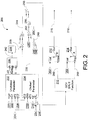
- FIG. 2 depicts a block diagram of an illustrative gas flow valve control algorithm 200 according to an exemplary embodiment of the invention.
- the algorithm 200 may be associated with the flow control module 116 of FIG. 1 .
- the algorithm 200 may produce a valve flow coefficient 258 for controlling one or more gas control valves in response to various parameters and measurements.
- the algorithm 200 may involve a series of calculations that can be used to actively control gas control valves (single, or multiples in parallel) to accurately meter fuel even when the gas control valves are operating unchoked.
- a desired gas turbine combustor energy flow rate 252 (e.g., BTU/sec) may be determined.
- the energy flow rate 252 may be based on a desired turbine load fuel command signal, also known as a fuel stroke reference (FSR) 250, which may be automatically determined by the controller 102 or selected by an operator. This value is generally represented as a percentage.
- the desired FSR 250 may be multiplied by a fuel energy per unit time of command 149 (e.g., BTU/sec/%), which may represent how much energy is required per unit of turbine load signal, or how much energy is present per unit of FSR. Multiplying the fuel energy per unit time of command 248 by the FSR 250 may provide an energy flow rate 252 (e.g., BTU/sec), which may represent the demand that is required for the turbine to reach the selected load.
- another calculation may be made to convert the previous energy flow rate 252 fuel command into a desired fuel flow rate 256 (e.g., LB/sec).
- the energy flow rate 252 may be divided by a gas energy per mass parameter 254 (e.g., BTU/LB), which may be a constant if the fuel source is very consistent, or may be provided from a sensor reading, for example, from a high-speed calorimeter or chromatograph to compensate for changes in the fuel energy content.
- the output of this calculation is a desired fuel flow rate 256 (e.g., LB/sec) to the combustor.
- the energy per mass parameter 254 e.g., BTU/LB
- the energy per mass parameter 254 may be manipulated intentionally and is intended to change.
- the universal valve flow equation can be represented as:
- the choked valve flow gain 238 can be used to determine how much the gas flow control valve 146 needs to be open to flow a certain amount of fuel by mass per unit time (e.g., CG/LB)/sec). Note that the output of this calculation will be the desired flow if the valves were choked.
- the unchoked flow parameter of the universal valve flow equation may be calculated in the unchoked parameter module 202.
- This version of the universal valve flow equation can be represented as:
- another calculation may be made by taking the sine value 208 of the median unchoked parameter 242, and multiplying the result 209 by the previously calculated choked valve flow gain 238.
- the median unchoked parameter 242 may be clamped between 1 and 0 via a constraining block 206.
- a value of 1 may represent a choked valve, whose flow would not vary with downstream pressure.
- the resulting median unchoked parameter 242 may then be multiplied by the choked valve gain 238 to produce an unchoked flow per control gas valve value. This value may then be inverted to produce gas flow gain 244 (e.g., CG/LB/sec).
- the gas flow gain 244 may be multiplied by the desired fuel flow rate 256 (e.g., LB/sec) determined previously. Multiplying these two values together may yield the required total valve flow control 258 for controlling desired fuel flow. In certain embodiments, this total valve flow control 258 may also be known as the CG.
- the next portion of the gas flow valve control algorithm 200 may depend on how many gas control valves 142, 146, are present in the system. If only one valve 146 is present, then the total valve flow control 258 may be the desired gas control value of that valve. However, if two or more valves 142, 146, are present, the total valve flow control 258 may be split among these valves 142, 146 using a gas control valve split function 210. Exemplary embodiments of the gas control valve split function 210 may enable, for example, holding one valve at a constant low flow value while the other valve is opened all the way, at which point, the first valve may then be released to continue opening. Another exemplary embodiment may include opening all valves to an equal amount.
- Still other complicated systems may utilize the gas control valve split function 210 to split the total valve flow control 258 to each valve such that each valve may be dynamically altered to reflect changing turbine conditions depending on the needs of the specific turbine, for example, combustor stability or emissions control.
- this portion of the algorithm may assign a desired control value N 260, 266 to each gas control valve 142, 146.
- lookup tables 262, 264 may be used to compute the gas valve control position commands 216, 218 to each gas control valve 142, 146 in order to determine what stroke to open each gas control valve 142, 146. It is assumed that the gas control valves 142, 146 will have been flow tested (or that a representative table has been provided by the manufacturer), which may allow a simple 1-d interpolation 212, 214 to determine valve stroke based on the desired control value N 260, 266 for each valve.
- the gas flow control algorithm may be fully implemented many times per second in order to accurately and continuously deliver a desired amount of fuel to reach a desired load in a gas turbine where the gas control valves may be choked or unchoked.
- a desired fuel command 250 and an inlet pressure parameter 224 may be received.
- a choked valve flow factor 238 and an unchoked valve flow factor 240 of the gas flow control valve 145 may be determined based at least in part on the inlet pressure parameter 224.
- a gas flow gain 244 may be determined based at least in part on the inlet pressure parameter, or on the choked valve flow factor 238 and the unchoked valve flow factor 240, as determined in optional block 304.
- a valve flow coefficient 258 may be determined based at least in part on the desired fuel command 250 and the gas flow gain 244.
- the gas flow control valve 146 may be controlled based at least in part on the valve flow coefficient 258.
- exemplary embodiments of the invention can provide the technical effects of creating certain systems and methods that can provide for higher loading and operation of a gas turbine under low pressure fuel supply conditions.
- embodiments of the invention may allow a fuel supply system to be designed with a low fuel supply pressure in mind, or it could be used for a normal high pressure system which is experiencing a low pressure fuel supply due to some type of system failure.
- exemplary embodiments of the invention can provide the technical effects of creating certain systems and methods that can provide for reduction in size (or elimination of) a fuel gas compressor (FGC).
- FGC fuel gas compressor
- a fuel gas compressor to pressurize the fuel supply
- a site which would normally require a FGC to eliminate the FGC altogether from the design. This could significantly reduce the cost and design complexity of such a system.
- exemplary embodiments of the invention can also provide the technical effects of creating certain systems and methods that can improve efficiency.
- the smaller gas compressor has a further aspect in that the smaller compressor will be significantly more efficient. This is because the gas compressor consumes energy in order to pressurize the fuel. Since a fuel system which utilizes the invention can operate with a lower fuel supply pressure, the gas compressor will pressurize to a lower pressure and therefore consume less energy. This energy savings can be as high as several megawatts, and can be a continuous energy savings at all times during the operation of the unit.
- exemplary embodiments of the invention can also provide the technical effects of creating certain systems and methods that can lead to relatively cheaper gas control valve (GCV) design.
- GCV gas control valve
- the use of the invention's control system could allow the purchase of cheaper normal valves for such systems, which could then be operated unchoked.
- exemplary embodiments of the invention can also provide the technical effects of creating certain systems and methods that can tolerate a simpler gas control valve design. For example, unchoked valves generally have a much higher flow capacity than choked valves. For very high fuel flow systems, use of the invention's control system may enable a fuel system to be designed with fewer gas control valves in parallel, thus reducing the complexity and cost of the system.
- the gas flow control system 100 and the gas flow valve control algorithm 200 may include any number of software applications that are executed to facilitate any of the operations.
- one or more I/O interfaces may facilitate communication between the gas flow control system 100 and the gas flow valve control algorithm 200, and one or more input/output devices.
- a universal serial bus port, a serial port, a disk drive, a CD-ROM drive, and/or one or more user interface devices such as a display, keyboard, keypad, mouse, control panel, touch screen display, microphone, etc.
- the one or more I/O interfaces may be utilized to receive or collect data and/or user instructions from a wide variety of input devices. Received data may be processed by one or more computer processors as desired in various embodiments of the invention and/or stored in one or more memory devices.
- One or more network interfaces may facilitate connection of the gas flow control system 100 and the gas flow valve control algorithm 200 inputs and outputs to one or more suitable networks and/or connections; for example, the connections that facilitate communication with any number of sensors associated with the system.
- the one or more network interfaces may further facilitate connection to one or more suitable networks; for example, a local area network, a wide area network, the Internet, a cellular network, a radio frequency network, a BluetoothTM enabled network, a Wi-FiTM enabled network, a satellite-based network, any wired network, any wireless network, etc., for communication with external devices and/or systems.
- embodiments of the invention may include the gas flow control system 100 and the gas flow valve control algorithm 200 with more or less of the blocks or components illustrated in FIGs. 1 and 2 .
- These computer-executable program instructions may be loaded onto a general-purpose computer, a special-purpose computer, a processor, or other programmable data processing apparatus to produce a particular machine, such that the instructions that execute on the computer, processor, or other programmable data processing apparatus create means for implementing one or more functions specified in the flow diagram block or blocks.
- These computer program instructions may also be stored in a computer-readable memory that can direct a computer or other programmable data processing apparatus to function in a particular manner, such that the instructions stored in the computer-readable memory produce an article of manufacture including instruction means that implement one or more functions specified in the flow diagram block or blocks.
- embodiments of the invention may provide for a computer program product, comprising a computer-usable medium having a computer-readable program code or program instructions embodied therein, said computer-readable program code adapted to be executed to implement one or more functions specified in the flow diagram block or blocks.
- the computer program instructions may also be loaded onto a computer or other programmable data processing apparatus to cause a series of operational elements or steps to be performed on the computer or other programmable apparatus to produce a computer-implemented process such that the instructions that execute on the computer or other programmable apparatus provide elements or steps for implementing the functions specified in the flow diagram block or blocks.
- blocks of the block diagrams and flow diagrams support combinations of means for performing the specified functions, combinations of elements or steps for performing the specified functions and program instruction means for performing the specified functions. It will also be understood that each block of the block diagrams and flow diagrams, and combinations of blocks in the block diagrams and flow diagrams, can be implemented by special-purpose, hardware-based computer systems that perform the specified functions, elements or steps, or combinations of special-purpose hardware and computer instructions.
Landscapes
- Engineering & Computer Science (AREA)
- Chemical & Material Sciences (AREA)
- Combustion & Propulsion (AREA)
- Mechanical Engineering (AREA)
- General Engineering & Computer Science (AREA)
- Physics & Mathematics (AREA)
- Fluid Mechanics (AREA)
- Flow Control (AREA)
- Feedback Control In General (AREA)
Description
- This invention generally relates to gas turbines, and more specifically to systems and methods for unchoked control of gas turbine fuel control valves.
- Gas turbines and other fuel consuming machines typically convert fuel energy into work, and the work may be used to drive an electrical generator, for example. The amount of work produced is dependent upon the fuel consumption rate and control valves are typically utilized to set the rate of fuel delivery to the combustion portion of the machine. For example, a gas flow control valve may be electronically or manually controlled to increase or decrease the fuel flow rate to a combustor in an attempt to meet the load demand of the machine. Under certain conditions, however, the fuel throughput may be limited, and thus the work throughput of the machine may be limited. For example, the turbine fuel supply system pressure may drop requiring a gas flow control valve to open significantly to satisfy the flow rate demand. In this mode of operation, the gas flow control valve may operate in an "un-choked" state, meaning that the fuel delivery rate is sensitive to changes in upstream fuel supply pressure as well as downstream valve outlet conditions. Conventional turbine systems typically operate in a "choked" state because downstream pressure changes due to changes in turbine cycle conditions, or changes in combustor pressure for example, can cause corresponding fuel rate spikes or oscillations. This method of operation is desirable for disturbance rejection so that transients in the upstream (fuel source) pressure and downstream (combustor) pressure cannot interrupt the steady flow of fuel to the turbine.
- Conventional gas turbine fuel control systems require a relatively high pressure gas fuel source so that the flow control valves may operate in the choked state. Typically, this fuel source will be at a much higher pressure than is required for the fuel metering system, and an additional pressure-regulating valve is often utilized to regulate the pressure to the gas flow control valve(s) to a desired set point. Typically, this pressure set point is high enough so that the gas flow control valve(s) will always operate choked.
-
US 2009/241510 describes a system and method to reduce the gas fuel supply pressure requirements of a gas turbine, which results in an increased operability range and a reduction in gas turbine trips. The gas turbine is allowed to start and operate at supply pressures determined as a function of ambient conditions and gas turbine compressor pressure ratio. This increases the operability window, and reduces or eliminates the need for gas fuel compressors.US 2007/101724 describes a method of controlling fuel flow to a combustor of a gas turbine engine during startup of the engine and includes determining a relationship between Cv and valve position for a flow control valve in a fuel supply to the combustor as a function of at least one real time parameter of fuel in the fuel supply. The method also includes determining a value of the at least one parameter of the fuel before initiating a flow of the fuel to the combustor, and then calculating a first actual Cv value for the flow control valve at a target flow rate using the determined value of the parameter. The method then includes positioning the flow control valve to a first position corresponding to the actual Cv value based upon the determined relationship between Cv and valve position, and initiating the flow of fuel to the combustor through the flow control valve. - The problem, however, is that sometimes the fuel source is at an insufficient pressure to choke the gas control valves at all load points, even if the pressure-regulating valve is opened fully to minimize pressure drop through the system. Therefore, a need remains for improved systems and methods for unchoked control of gas turbine fuel control valves.
- Some or all of the above needs may be addressed by certain embodiments of the invention. Certain embodiments of the invention may include systems and methods for unchoked control of gas turbine fuel control valves
- The present invention resides in a method and system for active control of a gas flow control valve as defined in the appended claims.
- Other embodiments and aspects of the invention are described in detail herein and are considered a part of the claimed invention. Other embodiments and aspects can be understood with reference to the following detailed description, accompanying drawings, and claims.
- Reference will now be made to the accompanying tables and drawings, which are not necessarily drawn to scale, and wherein:
-
FIG. 1 is a block diagram of an illustrative flow control system, according to an exemplary embodiment of the invention. -
FIG. 2 is a block diagram of an illustrative gas flow valve control algorithm according to an exemplary embodiment of the invention. -
FIG. 3 is a flow diagram of an exemplary method according to an exemplary embodiment of the invention. - Embodiments of the invention will be described more fully hereinafter with reference to the accompanying drawings, in which embodiments of the invention are shown. This invention may, however, be embodied in many different forms and should not be construed as limited to the embodiments set forth herein; rather, these embodiments are provided so that this disclosure will be thorough and complete, and will fully convey the scope of the invention to those skilled in the art. Like numbers refer to like elements throughout. The term "exemplary" as used throughout this document is defined to mean "example."
- Exemplary embodiments of the invention may allow stable and accurate fuel flow to a gas turbine, even when upstream fuel pressure is insufficient to allow the gas valves to be choked. Certain embodiments of the invention may allow the gas turbine to accurately meter fuel and maintain a steady load on the gas turbine regardless of whether the gas flow control valves are choked or unchoked. Certain embodiments of the invention allow the gas valves to be unchoked to provide a sufficient amount of fuel to maintain a desired turbine operating point. According to exemplary embodiments of the invention, the transition from choked to unchoked flow control (and vice versa) may be seamless.
- According to exemplary embodiments of the invention, various algorithms, sensors, and controls are provided for enabling choked or unchoked gas flow control valve operation in a gas turbine. These algorithms, sensors, and controls will now be described with reference to the accompanying figures.
-
FIG. 1 illustrates an exemplary gasflow control system 100 that may be utilized to control one or more gasflow control valves 146. According to exemplary embodiments of the invention, the gasflow control system 100 may include acontroller 102, a memory 104, one ormore processors 106, input/output (I/O)interfaces 108 and one ormore network interfaces 110. The memory 104 may include an operating system (OS) 112,data 114, and one or moreflow control modules 116. According to certain exemplary embodiments, theflow control modules 116 may be in communication with the one ormore processors 106 and may be utilized in determiningvarious system 100 flow parameters, based onvarious system inputs sensor measurement values 128, 132, and storeddata 114. - According to exemplary embodiments of the invention, the I/
O interfaces 108 and/or thenetwork interfaces 110 may receive control inputs for communication to theprocessors 106 and theflow control modules 116. The I/O interfaces 108 and/or thenetwork interfaces 110 may also providesignals 124 for controlling the pressure valve(s) 122, and signals 144, 148 for controlling the control valve(s) 142, 146 in thesystem 100, as will be described below. - According to exemplary embodiments of the invention, gas fuel for use in a
turbine combustor 150 may be supplied by afuel line 120. Thefuel line 120 may have an upstreamfuel line portion 119, a midstreamfuel line portion 121, and a downstreamfuel line portion 123. According to an exemplary embodiment of the invention, the fuel pressure in the midstreamfuel line portion 121 of thefuel line 120 may be controlled, at least in part, by apressure valve 122. According to an exemplary embodiment of the invention, the fuel pressure and/or fuel flow rate in the downstreamfuel line portion 123 may be controlled, at least in part, by a gasflow control valve 146. In certain exemplary embodiments, one or more additional gas flow control valve(s) 142, each with individually controllable fuel flow rates, may be utilized to provide additional fuel flow to additional downstream fuel line portions. In this embodiment, the fuel delivered and distributed among various combustor fuel nozzles may be individually controlled via flowvalve control signals - According to exemplary embodiments of the invention, the
controller 102 may be operable to continuously receive sensor, measurement, and/orexternal control signals controller 102 may be operable to compute and transmitcontrol signals various valves pressure valve 122 may receive pressurevalve control signals 124 from the controller 102 (or alternatively from an external control source) to provide a fuel pressure drop in thefuel line 120 from the upstreamfuel line portion 119 to the midstreamfuel line portion 121. - According to certain exemplary embodiments of the invention, one or
more sensors 126 may be utilized to monitor any number of parameters associated with the fuel, including pressure, temperature, flow rate, specific heat, specific gravity, fuel compressibility, etc. Thesensor signals 128 may be communicated to thecontroller 102 via the I/O interfaces 108 or thenetwork interfaces 110 for processing, and for inputs to theflow control module 116. According to exemplary embodiments, thesensors 126 may be placed at any suitable location(s) in the gas flow control system to measure and/or monitor the various fuel-related parameters. For example, sensors for measuring pressure, temperature, flow rate, specific heat, specific gravity, fuel compressibility, etc. may be located for sensing parameters in the upstream fuel line portion, 119, the midstreamfuel line portion 121, and/or the downstreamfuel line portion 123 of thefuel line 120. - According to exemplary embodiments of the invention, the controller may process the received
sensor signals 128, for example via theflow control module 116, and may provide one ormore control signals turbine 150. In an exemplary embodiment, the controller may provide a pressurevalve control signal 124 for controlling thepressure valve 122, and thereby, provide control of the pressure drop from the upstreamfuel line portion 119 to the midstreamfuel line portion 121. In an exemplary embodiment, the controller may provide a flowvalve control signal 148 for controlling the gasflow control valve 146, thereby controlling the flow of fuel to theturbine 150. In exemplary embodiments, anexternal command 154 may be received by thecontroller 102 and utilized for input in theflow control module 116. According to an exemplary embodiment, aload signal 152 may be received bycontroller 102 and utilized as a setpoint for commanding fuel to theturbine 150. - In accordance with other exemplary embodiments of the invention, the
flow control module 116 may include a split function that may be utilized in conjunction with the gasflow control system 100 to provide individually tailored gas flow through additional gasflow control valves 142 in response to additional flowvalve control signals 144 provided by thecontroller 102. In these multi-valve embodiments, the fuel flow can be individually and dynamically controlled through each gasflow control valves combustor 150 fuel nozzles, or to provide additional fuel throughput. Further details with regard tovarious controller 102 inputs and outputs, and the split function will be presented below in the description ofFIG. 2 . -
FIG. 2 depicts a block diagram of an illustrative gas flowvalve control algorithm 200 according to an exemplary embodiment of the invention. Thealgorithm 200 may be associated with theflow control module 116 ofFIG. 1 . In accordance with exemplary embodiments of the invention, thealgorithm 200 may produce avalve flow coefficient 258 for controlling one or more gas control valves in response to various parameters and measurements. According to exemplary embodiments of the invention, thealgorithm 200 may involve a series of calculations that can be used to actively control gas control valves (single, or multiples in parallel) to accurately meter fuel even when the gas control valves are operating unchoked. - In an exemplary embodiment, a desired gas turbine combustor energy flow rate 252 (e.g., BTU/sec) may be determined. The
energy flow rate 252 may be based on a desired turbine load fuel command signal, also known as a fuel stroke reference (FSR) 250, which may be automatically determined by thecontroller 102 or selected by an operator. This value is generally represented as a percentage. In an exemplary embodiment, the desiredFSR 250 may be multiplied by a fuel energy per unit time of command 149 (e.g., BTU/sec/%), which may represent how much energy is required per unit of turbine load signal, or how much energy is present per unit of FSR. Multiplying the fuel energy per unit time ofcommand 248 by theFSR 250 may provide an energy flow rate 252 (e.g., BTU/sec), which may represent the demand that is required for the turbine to reach the selected load. - In an exemplary embodiment, another calculation may be made to convert the previous
energy flow rate 252 fuel command into a desired fuel flow rate 256 (e.g., LB/sec). Theenergy flow rate 252 may be divided by a gas energy per mass parameter 254 (e.g., BTU/LB), which may be a constant if the fuel source is very consistent, or may be provided from a sensor reading, for example, from a high-speed calorimeter or chromatograph to compensate for changes in the fuel energy content. The output of this calculation is a desired fuel flow rate 256 (e.g., LB/sec) to the combustor. For some applications, the energy per mass parameter 254 (e.g., BTU/LB) may be manipulated intentionally and is intended to change. - In an exemplary embodiment, another calculation may be made involving the universal valve flow equation via the choked
parameter module 204. The universal valve flow equation can be represented as: -

specific gravity parameter 230, Z =fuel compressibility parameter 232, P2 =inlet pressure parameter 224, TR = fuel temperature 234 (modified by rankine conversion 236), C2 = specific heatratio correction factor 228. These inputs can be assumed or measured. The output of the chokedparameter module 204 is the choked valve flow gain 238 (e.g., CG/LB/sec). - In accordance with exemplary embodiments of the invention, the choked valve flow gain 238 can be used to determine how much the gas
flow control valve 146 needs to be open to flow a certain amount of fuel by mass per unit time (e.g., CG/LB)/sec). Note that the output of this calculation will be the desired flow if the valves were choked. - In an exemplary embodiment, another calculation may be made to determine if the valve is unchoked or not, and the extent to which the valve is unchoked. In accordance with an exemplary embodiment, the unchoked flow parameter of the universal valve flow equation may be calculated in the
unchoked parameter module 202. This version of the universal valve flow equation can be represented as: -

differential pressure 220, P2 =inlet pressure parameter 224, C2 = specific heatratio correction factor 228, and C1 =valve recovery factor 222. The output of theunchoked parameter module 202 is theunchoked valve factor 240. - In an exemplary embodiment, another calculation may be made by taking the
sine value 208 of themedian unchoked parameter 242, and multiplying theresult 209 by the previously calculated chokedvalve flow gain 238. Themedian unchoked parameter 242 may be clamped between 1 and 0 via a constrainingblock 206. For example, a value of 1 may represent a choked valve, whose flow would not vary with downstream pressure. The resulting medianunchoked parameter 242 may then be multiplied by the chokedvalve gain 238 to produce an unchoked flow per control gas valve value. This value may then be inverted to produce gas flow gain 244 (e.g., CG/LB/sec). - In accordance with exemplary embodiments of the invention, the gas flow gain 244 may be multiplied by the desired fuel flow rate 256 (e.g., LB/sec) determined previously. Multiplying these two values together may yield the required total
valve flow control 258 for controlling desired fuel flow. In certain embodiments, this totalvalve flow control 258 may also be known as the CG. - In accordance with certain embodiments of the invention, the next portion of the gas flow
valve control algorithm 200 may depend on how manygas control valves valve 146 is present, then the totalvalve flow control 258 may be the desired gas control value of that valve. However, if two ormore valves valve flow control 258 may be split among thesevalves function 210. Exemplary embodiments of the gas control valve splitfunction 210 may enable, for example, holding one valve at a constant low flow value while the other valve is opened all the way, at which point, the first valve may then be released to continue opening. Another exemplary embodiment may include opening all valves to an equal amount. Still other complicated systems may utilize the gas control valve splitfunction 210 to split the totalvalve flow control 258 to each valve such that each valve may be dynamically altered to reflect changing turbine conditions depending on the needs of the specific turbine, for example, combustor stability or emissions control. Regardless of the specific implementation, this portion of the algorithm may assign a desiredcontrol value N gas control valve - In an exemplary embodiment of the invention, lookup tables 262, 264 may be used to compute the gas valve control position commands 216, 218 to each
gas control valve gas control valve gas control valves d interpolation control value N - In accordance with exemplary embodiments, the gas flow control algorithm may be fully implemented many times per second in order to accurately and continuously deliver a desired amount of fuel to reach a desired load in a gas turbine where the gas control valves may be choked or unchoked.
- An
exemplary method 300 for active control of a gasflow control valve 146 will now be described with reference to the flowchart ofFIG. 3 . Inblock 302 and according to an exemplary embodiment of the invention, a desiredfuel command 250 and aninlet pressure parameter 224 may be received. According to an optional embodiment of the invention, and as depicted inoptional block 304, a chokedvalve flow factor 238 and an unchokedvalve flow factor 240 of the gas flow control valve 145 may be determined based at least in part on theinlet pressure parameter 224. Inblock 306, and according to an exemplary embodiment of the invention, a gas flow gain 244 may be determined based at least in part on the inlet pressure parameter, or on the chokedvalve flow factor 238 and the unchokedvalve flow factor 240, as determined inoptional block 304. Inblock 308, and according to an exemplary embodiment, avalve flow coefficient 258 may be determined based at least in part on the desiredfuel command 250 and thegas flow gain 244. And inblock 310, according to an exemplary embodiment, the gasflow control valve 146 may be controlled based at least in part on thevalve flow coefficient 258. - Accordingly, exemplary embodiments of the invention can provide the technical effects of creating certain systems and methods that can provide for higher loading and operation of a gas turbine under low pressure fuel supply conditions. For example, embodiments of the invention may allow a fuel supply system to be designed with a low fuel supply pressure in mind, or it could be used for a normal high pressure system which is experiencing a low pressure fuel supply due to some type of system failure.
- In addition, exemplary embodiments of the invention can provide the technical effects of creating certain systems and methods that can provide for reduction in size (or elimination of) a fuel gas compressor (FGC). For example, in installations that use a fuel gas compressor to pressurize the fuel supply, it may be possible through the use of the invention to use a smaller gas compressor, which may significantly reduce the price and size of the gas compressor. Also, depending on the gas pressure supplied from a plant's pipeline, it may allow a site which would normally require a FGC to eliminate the FGC altogether from the design. This could significantly reduce the cost and design complexity of such a system.
- Accordingly, exemplary embodiments of the invention can also provide the technical effects of creating certain systems and methods that can improve efficiency. For example, the smaller gas compressor has a further aspect in that the smaller compressor will be significantly more efficient. This is because the gas compressor consumes energy in order to pressurize the fuel. Since a fuel system which utilizes the invention can operate with a lower fuel supply pressure, the gas compressor will pressurize to a lower pressure and therefore consume less energy. This energy savings can be as high as several megawatts, and can be a continuous energy savings at all times during the operation of the unit.
- Accordingly, exemplary embodiments of the invention can also provide the technical effects of creating certain systems and methods that can lead to relatively cheaper gas control valve (GCV) design. For example, it may be possible to eliminate the use of expensive high-recovery GCVs for some systems. These expensive valves are designed to allow a lower fuel source pressure without allowing the valves to go unchoked. The use of the invention's control system could allow the purchase of cheaper normal valves for such systems, which could then be operated unchoked.
- Also, exemplary embodiments of the invention can also provide the technical effects of creating certain systems and methods that can tolerate a simpler gas control valve design. For example, unchoked valves generally have a much higher flow capacity than choked valves. For very high fuel flow systems, use of the invention's control system may enable a fuel system to be designed with fewer gas control valves in parallel, thus reducing the complexity and cost of the system.
- In exemplary embodiments of the invention, the gas
flow control system 100 and the gas flowvalve control algorithm 200 may include any number of software applications that are executed to facilitate any of the operations. - In exemplary embodiments, one or more I/O interfaces may facilitate communication between the gas
flow control system 100 and the gas flowvalve control algorithm 200, and one or more input/output devices. For example, a universal serial bus port, a serial port, a disk drive, a CD-ROM drive, and/or one or more user interface devices, such as a display, keyboard, keypad, mouse, control panel, touch screen display, microphone, etc., may facilitate user interaction with the gasflow control system 100 and the gas flowvalve control algorithm 200. The one or more I/O interfaces may be utilized to receive or collect data and/or user instructions from a wide variety of input devices. Received data may be processed by one or more computer processors as desired in various embodiments of the invention and/or stored in one or more memory devices. - One or more network interfaces may facilitate connection of the gas
flow control system 100 and the gas flowvalve control algorithm 200 inputs and outputs to one or more suitable networks and/or connections; for example, the connections that facilitate communication with any number of sensors associated with the system. The one or more network interfaces may further facilitate connection to one or more suitable networks; for example, a local area network, a wide area network, the Internet, a cellular network, a radio frequency network, a Bluetooth™ enabled network, a Wi-Fi™ enabled network, a satellite-based network, any wired network, any wireless network, etc., for communication with external devices and/or systems. - As desired, embodiments of the invention may include the gas
flow control system 100 and the gas flowvalve control algorithm 200 with more or less of the blocks or components illustrated inFIGs. 1 and2 . - The invention is described above with reference to block and flow diagrams of systems, methods, apparatuses, and/or computer program products according to exemplary embodiments of the invention. It will be understood that one or more blocks of the block diagrams and flow diagrams, and combinations of blocks in the block diagrams and flow diagrams, respectively, can be implemented by computer-executable program instructions. Likewise, some blocks of the block diagrams and flow diagrams may not necessarily need to be performed in the order presented, or may not necessarily need to be performed at all, according to some embodiments of the invention.
- These computer-executable program instructions may be loaded onto a general-purpose computer, a special-purpose computer, a processor, or other programmable data processing apparatus to produce a particular machine, such that the instructions that execute on the computer, processor, or other programmable data processing apparatus create means for implementing one or more functions specified in the flow diagram block or blocks. These computer program instructions may also be stored in a computer-readable memory that can direct a computer or other programmable data processing apparatus to function in a particular manner, such that the instructions stored in the computer-readable memory produce an article of manufacture including instruction means that implement one or more functions specified in the flow diagram block or blocks. As an example, embodiments of the invention may provide for a computer program product, comprising a computer-usable medium having a computer-readable program code or program instructions embodied therein, said computer-readable program code adapted to be executed to implement one or more functions specified in the flow diagram block or blocks. The computer program instructions may also be loaded onto a computer or other programmable data processing apparatus to cause a series of operational elements or steps to be performed on the computer or other programmable apparatus to produce a computer-implemented process such that the instructions that execute on the computer or other programmable apparatus provide elements or steps for implementing the functions specified in the flow diagram block or blocks.
- Accordingly, blocks of the block diagrams and flow diagrams support combinations of means for performing the specified functions, combinations of elements or steps for performing the specified functions and program instruction means for performing the specified functions. It will also be understood that each block of the block diagrams and flow diagrams, and combinations of blocks in the block diagrams and flow diagrams, can be implemented by special-purpose, hardware-based computer systems that perform the specified functions, elements or steps, or combinations of special-purpose hardware and computer instructions.
- While the invention has been described in connection with what is presently considered to be the most practical and various embodiments, it is to be understood that the invention is not to be limited to the disclosed embodiments, but on the contrary, is intended to cover various modifications and equivalent arrangements included within the scope of the appended claims. Although specific terms are employed herein, they are used in a generic and descriptive sense only and not for purposes of limitation.
- This written description uses examples to disclose the invention, including the preferred mode, and also to enable any person skilled in the art to practice the invention, including making and using any devices or systems and performing any incorporated methods. The patentable scope of the invention is defined in the claims, and may include other examples that occur to those skilled in the art. Such other examples are intended to be within the scope of the claims if they have structural elements that do not differ from the literal language of the claims, or if they include equivalent structural elements with insubstantial differences from the literal language of the claims.
Claims (14)
- A method for active control of a gas flow control valve (146), the method comprising:receiving a desired fuel command (250) and an inlet pressure parameter (224);determining a choked valve flow factor (238) and an unchoked valve flow factor (240) based at least in part on the inlet pressure parameter (224);determining a gas flow gain (244) based at least in part on either the choked valve flow factor (238) and an unchoked valve flow factor (240) or the inlet pressure parameter (224), wherein determining the gas flow gain (244) is by way of inverting the product of the choked valve flow factor (238) and an unchoked multiplier (209);determining a valve flow coefficient (258) based at least in part on the desired fuel command (250) and the gas flow gain (244); andcontrolling the gas flow control valve (146) based at least in part on the valve flow coefficient (258).
- The method of claim 1, wherein determining the choked valve flow factor (238) is further based on one or more of: a fuel specific gravity (230), a fuel compressibility parameter (232), a fuel temperature (234), or a fuel specific heat ratio correction factor (228).
- The method of any preceding claim, wherein determining the unchoked valve flow factor (240) is further based on one or more of: a gas control valve differential pressure (220), a fuel temperature (234), a fuel specific heat ratio correction factor, or a valve recovery factor (222).
- The method of any preceding claim, further comprising controlling a plurality of gas flow control valves (142, 146) based at least in part on a gas control valve split function (210) and one or more gas control valve position commands (216, 218) wherein the total valve flow gain (258) is selectively split to control the individual gas flow control valves (142, 146).
- The method of claim 4, wherein the one or more gas flow control valve position commands (216, 218) is based at least in part on a valve stroke per valve gain lookup table (262, 264).
- The method of any preceding claim, wherein determining a valve flow coefficient (258) is further based on one or more of a gas energy per mass parameter (254) or an energy required per unit of turbine load parameter (259).
- The method of any preceding claim, wherein the unchoked multiplier (209) is based at least in part on the unchoked valve flow factor (240) and is clamped between one and zero.
- A system (100) comprising:a gas turbine combustor (150);one or more gas flow control valves (146) coupled with the combustor (150); anda controller (102) having one or more processors (106) operable to:receive a desired fuel command (250) and an inlet pressure parameter (224);determine a choked valve flow factor (238) and an unchoked valve flow factor (240) based at least in part on the inlet pressure parameter (224);determine a gas flow gain (244) based at least in part on either the choked valve flow factor (238) and an unchoked valve flow factor (240) or the inlet pressure parameter (224), wherein determining the gas flow gain (244) is by way of inverting the product of the choked valve flow factor (238) and an unchoked multiplier (209);determine a valve flow coefficient (258) based at least in part on the desired fuel command (250) and the gas flow gain (244); andcontrol the gas flow control valve (146) based at least in part on the valve flow coefficient (258).
- The system (100) of claim 8, wherein the choked valve flow factor (238) is further based on one or more of: a fuel specific gravity (230), a fuel compressibility parameter (232), a fuel temperature (234), or a fuel specific heat ratio correction factor (228).
- The system (100) of claim 8 or claim 9, wherein the unchoked valve flow factor (240) is based on one or more of: a gas control valve differential pressure (220), a fuel temperature (234), a fuel specific heat ratio correction factor, or a valve recovery factor (222).
- The system (100) of any of claims 8 to 10, wherein the one or more processors (106) is further operable to control a plurality of gas flow control valves (142, 146) based at least in part on a gas control valve split function (210) and one or more gas control valve position commands (216, 218), wherein the total valve flow gain (258) is split to control the individual gas flow control valves (142, 146).
- The system (100) of claim 11, wherein the one or more gas control valve position commands (216, 218) is based at least in part on a valve stroke per valve gain lookup table (262, 264).
- The system (100) of any of claims 8 to 12, wherein the valve flow coefficient (258) is further based on one or more of: a gas energy per mass parameter (254) or an energy required per unit of turbine load parameter (259)
- The system (100) of claims 8 to 13, wherein the unchoked multiplier (209) is based at least in part on the unchoked valve flow factor (240) and is clamped between one and zero.
Applications Claiming Priority (2)
| Application Number | Priority Date | Filing Date | Title |
|---|---|---|---|
| US26501609P | 2009-11-30 | 2009-11-30 | |
| US12/688,179 US8712665B2 (en) | 2009-11-30 | 2010-01-15 | Systems and methods for unchoked control of gas turbine fuel gas control valves |
Publications (3)
| Publication Number | Publication Date |
|---|---|
| EP2333281A2 EP2333281A2 (en) | 2011-06-15 |
| EP2333281A3 EP2333281A3 (en) | 2014-06-18 |
| EP2333281B1 true EP2333281B1 (en) | 2017-08-23 |
Family
ID=43597821
Family Applications (1)
| Application Number | Title | Priority Date | Filing Date |
|---|---|---|---|
| EP10191345.7A Active EP2333281B1 (en) | 2009-11-30 | 2010-11-16 | Systems and methods for unchoked control of gas turbine fuel gas control valves |
Country Status (2)
| Country | Link |
|---|---|
| US (1) | US8712665B2 (en) |
| EP (1) | EP2333281B1 (en) |
Families Citing this family (12)
| Publication number | Priority date | Publication date | Assignee | Title |
|---|---|---|---|---|
| US8127556B2 (en) * | 2008-10-08 | 2012-03-06 | General Electric Company | Method for operating a turbomachine having a syngas fuel supply system and a non-syngas fuel supply system |
| US8712665B2 (en) * | 2009-11-30 | 2014-04-29 | General Electric Company | Systems and methods for unchoked control of gas turbine fuel gas control valves |
| US20120180873A1 (en) * | 2011-01-14 | 2012-07-19 | General Electric Company | Method for replicating a pressure control valve with adjustable response characteristic |
| US9243804B2 (en) * | 2011-10-24 | 2016-01-26 | General Electric Company | System for turbine combustor fuel mixing |
| KR101574040B1 (en) | 2012-01-13 | 2015-12-02 | 미츠비시 히타치 파워 시스템즈 가부시키가이샤 | Fuel supply device, fuel flow volume control device, and gas turbine electricity generation plant |
| US20140137561A1 (en) * | 2012-11-19 | 2014-05-22 | General Electric Company | System and method for reducing modal coupling of combustion dynamics |
| US20140294559A1 (en) * | 2013-03-28 | 2014-10-02 | Solar Turbines Incorporated | Multiple mode gas turbine engine gas fuel system with integrated control |
| US8919129B2 (en) * | 2013-03-28 | 2014-12-30 | Solar Turbines Inc. | Low flow correction for gas turbine engine fuel valve characteristics |
| US9371917B2 (en) * | 2013-04-30 | 2016-06-21 | General Electric Company | Fuel conditioning system |
| US10830156B2 (en) * | 2014-02-19 | 2020-11-10 | Siemens Aktiengesellschaft | Fuel supply pipeline system for gas turbine |
| US10591161B2 (en) | 2018-06-09 | 2020-03-17 | Honeywell International Inc. | Systems and methods for valve and/or combustion applicance control |
| US20230036266A1 (en) * | 2021-07-27 | 2023-02-02 | Pratt & Whitney Canada Corp. | Controlling gaseous fuel flow |
Family Cites Families (13)
| Publication number | Priority date | Publication date | Assignee | Title |
|---|---|---|---|---|
| US4146051A (en) * | 1976-01-10 | 1979-03-27 | Lucas Industries Limited | Fluid flow control system |
| JPH10159585A (en) | 1996-11-27 | 1998-06-16 | Toshiba Corp | Gas turbine fuel supplying method and device thereof |
| US6813875B2 (en) * | 2000-01-07 | 2004-11-09 | Honda Giken Kogyo Kabushiki Kaisha | Control system for gas-turbine engine |
| US6631334B2 (en) * | 2000-12-26 | 2003-10-07 | Mks Instruments, Inc. | Pressure-based mass flow controller system |
| US6795780B1 (en) * | 2001-09-27 | 2004-09-21 | Thomas Allen Hyde | Fluid energy pulse test system—transient, ramp, steady state tests |
| US7055395B2 (en) * | 2002-08-16 | 2006-06-06 | General Electric Company | Sulfur deposition control method and related control algorithm |
| US6980898B2 (en) * | 2003-12-19 | 2005-12-27 | Daimlerchrysler Corporation | Downshift acceleration control |
| JP4119908B2 (en) * | 2005-09-14 | 2008-07-16 | 三菱重工業株式会社 | Combustion control device for gas turbine |
| US7481061B2 (en) * | 2005-11-10 | 2009-01-27 | Siemens Energy, Inc. | Fuel control for starting a gas turbine engine |
| US7549293B2 (en) * | 2006-02-15 | 2009-06-23 | General Electric Company | Pressure control method to reduce gas turbine fuel supply pressure requirements |
| US7607410B2 (en) * | 2006-06-12 | 2009-10-27 | Ford Global Technologies, Llc | System and method of controlling fuel delivery during positive valve overlap operation of an engine start |
| US8127556B2 (en) * | 2008-10-08 | 2012-03-06 | General Electric Company | Method for operating a turbomachine having a syngas fuel supply system and a non-syngas fuel supply system |
| US8712665B2 (en) * | 2009-11-30 | 2014-04-29 | General Electric Company | Systems and methods for unchoked control of gas turbine fuel gas control valves |
-
2010
- 2010-01-15 US US12/688,179 patent/US8712665B2/en active Active
- 2010-11-16 EP EP10191345.7A patent/EP2333281B1/en active Active
Non-Patent Citations (1)
| Title |
|---|
| None * |
Also Published As
| Publication number | Publication date |
|---|---|
| EP2333281A2 (en) | 2011-06-15 |
| US20110130941A1 (en) | 2011-06-02 |
| EP2333281A3 (en) | 2014-06-18 |
| US8712665B2 (en) | 2014-04-29 |
Similar Documents
| Publication | Publication Date | Title |
|---|---|---|
| EP2333281B1 (en) | Systems and methods for unchoked control of gas turbine fuel gas control valves | |
| EP2333280B1 (en) | Methods for controlling fuel mixing | |
| EP2341232B1 (en) | Method for controlling fuel flow within a machine | |
| EP2562612B1 (en) | Methods and systems for gas turbine modeling using adaptive kalman filter | |
| EP2570877A1 (en) | System and method for simulating gas turbine operation | |
| US20080010966A1 (en) | System and apparatus for gas turbine engine lean blowout avoidance | |
| EP2434127A2 (en) | Methods and systems for modeling turbine operation | |
| EP2423489A2 (en) | Methods for controlling fuel splits to a gas turbine combustor | |
| EP3191699B1 (en) | Bulk flame temperature regulator for dry low emission engines | |
| JP2009162230A (en) | Method and system for materializing real-time comparison with using alternative control system on turbine | |
| CN103946516A (en) | Valve control device, gas turbine, and valve control method | |
| US20150142188A1 (en) | Automated Commissioning of a Gas Turbine Combustion Control System | |
| JP2017115867A (en) | Combined probabilistic control in gas turbine tuning for power output-emissions parameters with scaling factor, and related control systems, computer program products and methods | |
| JP2017115871A (en) | Application of combined probabilistic control in gas turbine tuning for power output-emissions parameters with scaling factor, and related control systems, computer program products and methods | |
| EP2865865B1 (en) | Method and system for gas turbine power augmentation using steam injection | |
| EP3974634A1 (en) | Temperature based gas turbine control and method | |
| CN107560864B (en) | Method and apparatus for scale monitoring and prediction in combustors | |
| CN108119237B (en) | Model-free combustion power auto-tuning | |
| RU2181854C1 (en) | Method for controlling operation of set of aggregates of compressor shop | |
| EP2901020B1 (en) | Compressor test rig with pressure ratio targetting by throttling |
Legal Events
| Date | Code | Title | Description |
|---|---|---|---|
| PUAI | Public reference made under article 153(3) epc to a published international application that has entered the european phase |
Free format text: ORIGINAL CODE: 0009012 |
|
| AK | Designated contracting states |
Kind code of ref document: A2 Designated state(s): AL AT BE BG CH CY CZ DE DK EE ES FI FR GB GR HR HU IE IS IT LI LT LU LV MC MK MT NL NO PL PT RO RS SE SI SK SM TR |
|
| AX | Request for extension of the european patent |
Extension state: BA ME |
|
| PUAL | Search report despatched |
Free format text: ORIGINAL CODE: 0009013 |
|
| AK | Designated contracting states |
Kind code of ref document: A3 Designated state(s): AL AT BE BG CH CY CZ DE DK EE ES FI FR GB GR HR HU IE IS IT LI LT LU LV MC MK MT NL NO PL PT RO RS SE SI SK SM TR |
|
| AX | Request for extension of the european patent |
Extension state: BA ME |
|
| RIC1 | Information provided on ipc code assigned before grant |
Ipc: F02C 7/232 20060101ALI20140513BHEP Ipc: F02C 9/32 20060101ALI20140513BHEP Ipc: F02C 7/22 20060101AFI20140513BHEP Ipc: F02C 9/24 20060101ALI20140513BHEP Ipc: F02C 9/26 20060101ALI20140513BHEP |
|
| 17P | Request for examination filed |
Effective date: 20141218 |
|
| RBV | Designated contracting states (corrected) |
Designated state(s): AL AT BE BG CH CY CZ DE DK EE ES FI FR GB GR HR HU IE IS IT LI LT LU LV MC MK MT NL NO PL PT RO RS SE SI SK SM TR |
|
| GRAP | Despatch of communication of intention to grant a patent |
Free format text: ORIGINAL CODE: EPIDOSNIGR1 |
|
| RIC1 | Information provided on ipc code assigned before grant |
Ipc: F02C 9/32 20060101ALI20170301BHEP Ipc: F02C 7/232 20060101ALI20170301BHEP Ipc: F02C 7/22 20060101AFI20170301BHEP Ipc: F02C 9/26 20060101ALI20170301BHEP Ipc: F02C 9/24 20060101ALI20170301BHEP |
|
| INTG | Intention to grant announced |
Effective date: 20170329 |
|
| GRAS | Grant fee paid |
Free format text: ORIGINAL CODE: EPIDOSNIGR3 |
|
| GRAA | (expected) grant |
Free format text: ORIGINAL CODE: 0009210 |
|
| AK | Designated contracting states |
Kind code of ref document: B1 Designated state(s): AL AT BE BG CH CY CZ DE DK EE ES FI FR GB GR HR HU IE IS IT LI LT LU LV MC MK MT NL NO PL PT RO RS SE SI SK SM TR |
|
| REG | Reference to a national code |
Ref country code: GB Ref legal event code: FG4D |
|
| REG | Reference to a national code |
Ref country code: CH Ref legal event code: EP |
|
| REG | Reference to a national code |
Ref country code: AT Ref legal event code: REF Ref document number: 921607 Country of ref document: AT Kind code of ref document: T Effective date: 20170915 |
|
| REG | Reference to a national code |
Ref country code: IE Ref legal event code: FG4D |
|
| REG | Reference to a national code |
Ref country code: DE Ref legal event code: R096 Ref document number: 602010044570 Country of ref document: DE |
|
| REG | Reference to a national code |
Ref country code: FR Ref legal event code: PLFP Year of fee payment: 8 |
|
| REG | Reference to a national code |
Ref country code: NL Ref legal event code: MP Effective date: 20170823 |
|
| REG | Reference to a national code |
Ref country code: LT Ref legal event code: MG4D |
|
| REG | Reference to a national code |
Ref country code: AT Ref legal event code: MK05 Ref document number: 921607 Country of ref document: AT Kind code of ref document: T Effective date: 20170823 |
|
| PG25 | Lapsed in a contracting state [announced via postgrant information from national office to epo] |
Ref country code: NO Free format text: LAPSE BECAUSE OF FAILURE TO SUBMIT A TRANSLATION OF THE DESCRIPTION OR TO PAY THE FEE WITHIN THE PRESCRIBED TIME-LIMIT Effective date: 20171123 Ref country code: AT Free format text: LAPSE BECAUSE OF FAILURE TO SUBMIT A TRANSLATION OF THE DESCRIPTION OR TO PAY THE FEE WITHIN THE PRESCRIBED TIME-LIMIT Effective date: 20170823 Ref country code: SE Free format text: LAPSE BECAUSE OF FAILURE TO SUBMIT A TRANSLATION OF THE DESCRIPTION OR TO PAY THE FEE WITHIN THE PRESCRIBED TIME-LIMIT Effective date: 20170823 Ref country code: LT Free format text: LAPSE BECAUSE OF FAILURE TO SUBMIT A TRANSLATION OF THE DESCRIPTION OR TO PAY THE FEE WITHIN THE PRESCRIBED TIME-LIMIT Effective date: 20170823 Ref country code: HR Free format text: LAPSE BECAUSE OF FAILURE TO SUBMIT A TRANSLATION OF THE DESCRIPTION OR TO PAY THE FEE WITHIN THE PRESCRIBED TIME-LIMIT Effective date: 20170823 Ref country code: NL Free format text: LAPSE BECAUSE OF FAILURE TO SUBMIT A TRANSLATION OF THE DESCRIPTION OR TO PAY THE FEE WITHIN THE PRESCRIBED TIME-LIMIT Effective date: 20170823 Ref country code: FI Free format text: LAPSE BECAUSE OF FAILURE TO SUBMIT A TRANSLATION OF THE DESCRIPTION OR TO PAY THE FEE WITHIN THE PRESCRIBED TIME-LIMIT Effective date: 20170823 |
|
| PG25 | Lapsed in a contracting state [announced via postgrant information from national office to epo] |
Ref country code: RS Free format text: LAPSE BECAUSE OF FAILURE TO SUBMIT A TRANSLATION OF THE DESCRIPTION OR TO PAY THE FEE WITHIN THE PRESCRIBED TIME-LIMIT Effective date: 20170823 Ref country code: LV Free format text: LAPSE BECAUSE OF FAILURE TO SUBMIT A TRANSLATION OF THE DESCRIPTION OR TO PAY THE FEE WITHIN THE PRESCRIBED TIME-LIMIT Effective date: 20170823 Ref country code: IS Free format text: LAPSE BECAUSE OF FAILURE TO SUBMIT A TRANSLATION OF THE DESCRIPTION OR TO PAY THE FEE WITHIN THE PRESCRIBED TIME-LIMIT Effective date: 20171223 Ref country code: BG Free format text: LAPSE BECAUSE OF FAILURE TO SUBMIT A TRANSLATION OF THE DESCRIPTION OR TO PAY THE FEE WITHIN THE PRESCRIBED TIME-LIMIT Effective date: 20171123 Ref country code: GR Free format text: LAPSE BECAUSE OF FAILURE TO SUBMIT A TRANSLATION OF THE DESCRIPTION OR TO PAY THE FEE WITHIN THE PRESCRIBED TIME-LIMIT Effective date: 20171124 Ref country code: ES Free format text: LAPSE BECAUSE OF FAILURE TO SUBMIT A TRANSLATION OF THE DESCRIPTION OR TO PAY THE FEE WITHIN THE PRESCRIBED TIME-LIMIT Effective date: 20170823 Ref country code: PL Free format text: LAPSE BECAUSE OF FAILURE TO SUBMIT A TRANSLATION OF THE DESCRIPTION OR TO PAY THE FEE WITHIN THE PRESCRIBED TIME-LIMIT Effective date: 20170823 |
|
| PG25 | Lapsed in a contracting state [announced via postgrant information from national office to epo] |
Ref country code: RO Free format text: LAPSE BECAUSE OF FAILURE TO SUBMIT A TRANSLATION OF THE DESCRIPTION OR TO PAY THE FEE WITHIN THE PRESCRIBED TIME-LIMIT Effective date: 20170823 Ref country code: DK Free format text: LAPSE BECAUSE OF FAILURE TO SUBMIT A TRANSLATION OF THE DESCRIPTION OR TO PAY THE FEE WITHIN THE PRESCRIBED TIME-LIMIT Effective date: 20170823 |
|
| REG | Reference to a national code |
Ref country code: DE Ref legal event code: R097 Ref document number: 602010044570 Country of ref document: DE |
|
| PG25 | Lapsed in a contracting state [announced via postgrant information from national office to epo] |
Ref country code: SM Free format text: LAPSE BECAUSE OF FAILURE TO SUBMIT A TRANSLATION OF THE DESCRIPTION OR TO PAY THE FEE WITHIN THE PRESCRIBED TIME-LIMIT Effective date: 20170823 Ref country code: IT Free format text: LAPSE BECAUSE OF FAILURE TO SUBMIT A TRANSLATION OF THE DESCRIPTION OR TO PAY THE FEE WITHIN THE PRESCRIBED TIME-LIMIT Effective date: 20170823 Ref country code: SK Free format text: LAPSE BECAUSE OF FAILURE TO SUBMIT A TRANSLATION OF THE DESCRIPTION OR TO PAY THE FEE WITHIN THE PRESCRIBED TIME-LIMIT Effective date: 20170823 Ref country code: EE Free format text: LAPSE BECAUSE OF FAILURE TO SUBMIT A TRANSLATION OF THE DESCRIPTION OR TO PAY THE FEE WITHIN THE PRESCRIBED TIME-LIMIT Effective date: 20170823 |
|
| PG25 | Lapsed in a contracting state [announced via postgrant information from national office to epo] |
Ref country code: MC Free format text: LAPSE BECAUSE OF FAILURE TO SUBMIT A TRANSLATION OF THE DESCRIPTION OR TO PAY THE FEE WITHIN THE PRESCRIBED TIME-LIMIT Effective date: 20170823 |
|
| PLBE | No opposition filed within time limit |
Free format text: ORIGINAL CODE: 0009261 |
|
| STAA | Information on the status of an ep patent application or granted ep patent |
Free format text: STATUS: NO OPPOSITION FILED WITHIN TIME LIMIT |
|
| GBPC | Gb: european patent ceased through non-payment of renewal fee |
Effective date: 20171123 |
|
| 26N | No opposition filed |
Effective date: 20180524 |
|
| PG25 | Lapsed in a contracting state [announced via postgrant information from national office to epo] |
Ref country code: SI Free format text: LAPSE BECAUSE OF FAILURE TO SUBMIT A TRANSLATION OF THE DESCRIPTION OR TO PAY THE FEE WITHIN THE PRESCRIBED TIME-LIMIT Effective date: 20170823 Ref country code: LU Free format text: LAPSE BECAUSE OF NON-PAYMENT OF DUE FEES Effective date: 20171116 |
|
| REG | Reference to a national code |
Ref country code: BE Ref legal event code: MM Effective date: 20171130 |
|
| REG | Reference to a national code |
Ref country code: IE Ref legal event code: MM4A |
|
| PG25 | Lapsed in a contracting state [announced via postgrant information from national office to epo] |
Ref country code: MT Free format text: LAPSE BECAUSE OF NON-PAYMENT OF DUE FEES Effective date: 20171116 |
|
| REG | Reference to a national code |
Ref country code: FR Ref legal event code: PLFP Year of fee payment: 9 |
|
| PG25 | Lapsed in a contracting state [announced via postgrant information from national office to epo] |
Ref country code: IE Free format text: LAPSE BECAUSE OF NON-PAYMENT OF DUE FEES Effective date: 20171116 |
|
| PG25 | Lapsed in a contracting state [announced via postgrant information from national office to epo] |
Ref country code: BE Free format text: LAPSE BECAUSE OF NON-PAYMENT OF DUE FEES Effective date: 20171130 Ref country code: GB Free format text: LAPSE BECAUSE OF NON-PAYMENT OF DUE FEES Effective date: 20171123 |
|
| PG25 | Lapsed in a contracting state [announced via postgrant information from national office to epo] |
Ref country code: HU Free format text: LAPSE BECAUSE OF FAILURE TO SUBMIT A TRANSLATION OF THE DESCRIPTION OR TO PAY THE FEE WITHIN THE PRESCRIBED TIME-LIMIT; INVALID AB INITIO Effective date: 20101116 |
|
| PG25 | Lapsed in a contracting state [announced via postgrant information from national office to epo] |
Ref country code: CY Free format text: LAPSE BECAUSE OF NON-PAYMENT OF DUE FEES Effective date: 20170823 |
|
| PG25 | Lapsed in a contracting state [announced via postgrant information from national office to epo] |
Ref country code: MK Free format text: LAPSE BECAUSE OF FAILURE TO SUBMIT A TRANSLATION OF THE DESCRIPTION OR TO PAY THE FEE WITHIN THE PRESCRIBED TIME-LIMIT Effective date: 20170823 |
|
| PGFP | Annual fee paid to national office [announced via postgrant information from national office to epo] |
Ref country code: CZ Payment date: 20191025 Year of fee payment: 10 |
|
| PG25 | Lapsed in a contracting state [announced via postgrant information from national office to epo] |
Ref country code: TR Free format text: LAPSE BECAUSE OF FAILURE TO SUBMIT A TRANSLATION OF THE DESCRIPTION OR TO PAY THE FEE WITHIN THE PRESCRIBED TIME-LIMIT Effective date: 20170823 |
|
| PGFP | Annual fee paid to national office [announced via postgrant information from national office to epo] |
Ref country code: CH Payment date: 20191022 Year of fee payment: 10 |
|
| PG25 | Lapsed in a contracting state [announced via postgrant information from national office to epo] |
Ref country code: PT Free format text: LAPSE BECAUSE OF FAILURE TO SUBMIT A TRANSLATION OF THE DESCRIPTION OR TO PAY THE FEE WITHIN THE PRESCRIBED TIME-LIMIT Effective date: 20170823 |
|
| PG25 | Lapsed in a contracting state [announced via postgrant information from national office to epo] |
Ref country code: AL Free format text: LAPSE BECAUSE OF FAILURE TO SUBMIT A TRANSLATION OF THE DESCRIPTION OR TO PAY THE FEE WITHIN THE PRESCRIBED TIME-LIMIT Effective date: 20170823 |
|
| REG | Reference to a national code |
Ref country code: CH Ref legal event code: PL |
|
| PG25 | Lapsed in a contracting state [announced via postgrant information from national office to epo] |
Ref country code: CZ Free format text: LAPSE BECAUSE OF NON-PAYMENT OF DUE FEES Effective date: 20201116 |
|
| PG25 | Lapsed in a contracting state [announced via postgrant information from national office to epo] |
Ref country code: CH Free format text: LAPSE BECAUSE OF NON-PAYMENT OF DUE FEES Effective date: 20201130 Ref country code: LI Free format text: LAPSE BECAUSE OF NON-PAYMENT OF DUE FEES Effective date: 20201130 |
|
| P01 | Opt-out of the competence of the unified patent court (upc) registered |
Effective date: 20230522 |
|
| REG | Reference to a national code |
Ref country code: DE Ref legal event code: R081 Ref document number: 602010044570 Country of ref document: DE Owner name: GENERAL ELECTRIC TECHNOLOGY GMBH, CH Free format text: FORMER OWNER: GENERAL ELECTRIC COMPANY, SCHENECTADY, NY, US |
|
| PGFP | Annual fee paid to national office [announced via postgrant information from national office to epo] |
Ref country code: FR Payment date: 20231019 Year of fee payment: 14 Ref country code: DE Payment date: 20231019 Year of fee payment: 14 |