EP2333274A1 - Engine - Google Patents
Engine Download PDFInfo
- Publication number
- EP2333274A1 EP2333274A1 EP09819080A EP09819080A EP2333274A1 EP 2333274 A1 EP2333274 A1 EP 2333274A1 EP 09819080 A EP09819080 A EP 09819080A EP 09819080 A EP09819080 A EP 09819080A EP 2333274 A1 EP2333274 A1 EP 2333274A1
- Authority
- EP
- European Patent Office
- Prior art keywords
- supercharger
- variable
- supercharging pressure
- intake air
- variable actuator
- Prior art date
- Legal status (The legal status is an assumption and is not a legal conclusion. Google has not performed a legal analysis and makes no representation as to the accuracy of the status listed.)
- Ceased
Links
Images


Classifications
-
- F—MECHANICAL ENGINEERING; LIGHTING; HEATING; WEAPONS; BLASTING
- F02—COMBUSTION ENGINES; HOT-GAS OR COMBUSTION-PRODUCT ENGINE PLANTS
- F02D—CONTROLLING COMBUSTION ENGINES
- F02D23/00—Controlling engines characterised by their being supercharged
-
- F—MECHANICAL ENGINEERING; LIGHTING; HEATING; WEAPONS; BLASTING
- F02—COMBUSTION ENGINES; HOT-GAS OR COMBUSTION-PRODUCT ENGINE PLANTS
- F02B—INTERNAL-COMBUSTION PISTON ENGINES; COMBUSTION ENGINES IN GENERAL
- F02B37/00—Engines characterised by provision of pumps driven at least for part of the time by exhaust
- F02B37/001—Engines characterised by provision of pumps driven at least for part of the time by exhaust using exhaust drives arranged in parallel
-
- F—MECHANICAL ENGINEERING; LIGHTING; HEATING; WEAPONS; BLASTING
- F02—COMBUSTION ENGINES; HOT-GAS OR COMBUSTION-PRODUCT ENGINE PLANTS
- F02B—INTERNAL-COMBUSTION PISTON ENGINES; COMBUSTION ENGINES IN GENERAL
- F02B37/00—Engines characterised by provision of pumps driven at least for part of the time by exhaust
- F02B37/007—Engines characterised by provision of pumps driven at least for part of the time by exhaust with exhaust-driven pumps arranged in parallel, e.g. at least one pump supplying alternatively
-
- F—MECHANICAL ENGINEERING; LIGHTING; HEATING; WEAPONS; BLASTING
- F02—COMBUSTION ENGINES; HOT-GAS OR COMBUSTION-PRODUCT ENGINE PLANTS
- F02B—INTERNAL-COMBUSTION PISTON ENGINES; COMBUSTION ENGINES IN GENERAL
- F02B37/00—Engines characterised by provision of pumps driven at least for part of the time by exhaust
- F02B37/12—Control of the pumps
- F02B37/18—Control of the pumps by bypassing exhaust from the inlet to the outlet of turbine or to the atmosphere
-
- F—MECHANICAL ENGINEERING; LIGHTING; HEATING; WEAPONS; BLASTING
- F02—COMBUSTION ENGINES; HOT-GAS OR COMBUSTION-PRODUCT ENGINE PLANTS
- F02B—INTERNAL-COMBUSTION PISTON ENGINES; COMBUSTION ENGINES IN GENERAL
- F02B37/00—Engines characterised by provision of pumps driven at least for part of the time by exhaust
- F02B37/12—Control of the pumps
- F02B37/22—Control of the pumps by varying cross-section of exhaust passages or air passages, e.g. by throttling turbine inlets or outlets or by varying effective number of guide conduits
-
- F—MECHANICAL ENGINEERING; LIGHTING; HEATING; WEAPONS; BLASTING
- F02—COMBUSTION ENGINES; HOT-GAS OR COMBUSTION-PRODUCT ENGINE PLANTS
- F02B—INTERNAL-COMBUSTION PISTON ENGINES; COMBUSTION ENGINES IN GENERAL
- F02B37/00—Engines characterised by provision of pumps driven at least for part of the time by exhaust
- F02B37/12—Control of the pumps
- F02B37/24—Control of the pumps by using pumps or turbines with adjustable guide vanes
-
- F—MECHANICAL ENGINEERING; LIGHTING; HEATING; WEAPONS; BLASTING
- F02—COMBUSTION ENGINES; HOT-GAS OR COMBUSTION-PRODUCT ENGINE PLANTS
- F02D—CONTROLLING COMBUSTION ENGINES
- F02D41/00—Electrical control of supply of combustible mixture or its constituents
- F02D41/0002—Controlling intake air
- F02D41/0007—Controlling intake air for control of turbo-charged or super-charged engines
-
- F—MECHANICAL ENGINEERING; LIGHTING; HEATING; WEAPONS; BLASTING
- F02—COMBUSTION ENGINES; HOT-GAS OR COMBUSTION-PRODUCT ENGINE PLANTS
- F02B—INTERNAL-COMBUSTION PISTON ENGINES; COMBUSTION ENGINES IN GENERAL
- F02B37/00—Engines characterised by provision of pumps driven at least for part of the time by exhaust
- F02B37/12—Control of the pumps
- F02B2037/122—Control of rotational speed of the pump
-
- F—MECHANICAL ENGINEERING; LIGHTING; HEATING; WEAPONS; BLASTING
- F02—COMBUSTION ENGINES; HOT-GAS OR COMBUSTION-PRODUCT ENGINE PLANTS
- F02D—CONTROLLING COMBUSTION ENGINES
- F02D2200/00—Input parameters for engine control
- F02D2200/02—Input parameters for engine control the parameters being related to the engine
- F02D2200/04—Engine intake system parameters
- F02D2200/0406—Intake manifold pressure
-
- Y—GENERAL TAGGING OF NEW TECHNOLOGICAL DEVELOPMENTS; GENERAL TAGGING OF CROSS-SECTIONAL TECHNOLOGIES SPANNING OVER SEVERAL SECTIONS OF THE IPC; TECHNICAL SUBJECTS COVERED BY FORMER USPC CROSS-REFERENCE ART COLLECTIONS [XRACs] AND DIGESTS
- Y02—TECHNOLOGIES OR APPLICATIONS FOR MITIGATION OR ADAPTATION AGAINST CLIMATE CHANGE
- Y02T—CLIMATE CHANGE MITIGATION TECHNOLOGIES RELATED TO TRANSPORTATION
- Y02T10/00—Road transport of goods or passengers
- Y02T10/10—Internal combustion engine [ICE] based vehicles
- Y02T10/12—Improving ICE efficiencies
Definitions
- the present invention relates to an art of control of an engine having a variable parallel supercharging system.
- a supercharging system in which two superchargers are arranged about one engine.
- two superchargers compress intake air flowing in two intake paths.
- two superchargers compress intake air flowing in one intake path.
- the Patent Literature 1 discloses an engine having a so-called sequential twin turbo which is a form of the series supercharging system.
- a supercharger of variable capacity type is also known in which exhaust gas is introduced to a turbine constituting the supercharger while controlling flow rate suitably so as to improve supercharging efficiency.
- a parallel supercharging system in which two superchargers compress intake air flowing in two intake paths and at least one of the superchargers is variable capacity type is defined as a variable parallel supercharging system.
- Patent Literature 1 the Japanese Patent Laid Open Gazette Hei. 5-288111
- the purpose of the present invention is to provide an engine and a control method which can control accurately a variable parallel supercharging system.
- an engine in which intake air distributed to cylinders is supplied through a first intake path and a second intake path, and exhaust gas collected from the cylinders is discharged through a first exhaust path and a second exhaust path includes a variable parallel supercharging system comprising a first supercharger which is driven by exhaust gas flowing in a first exhaust path and pressurizes intake air flowing in a first intake path, and a second supercharger which is driven by exhaust gas flowing in a second exhaust path and pressurizes intake air flowing in a second intake air route, a supercharging pressure sensor detecting pressure of the intake air pressurized by the first supercharger and the second supercharger, a first supercharger rotation sensor detecting supercharger rotational speed of the first supercharger, a second supercharger rotation sensor detecting supercharger rotational speed of the second supercharger, a first variable actuator controlling capacity of the first supercharger, a second variable actuator controlling capacity of the second supercharger, and a control device enabling the first
- the engine according to the first aspect further includes a bypass path connecting the part of the first exhaust path upstream the first supercharger to the part of the second exhaust path upstream the second supercharger, a bypasses flow rate control valve controlling flow rate of exhaust gas flowing in the bypass path, and a control device enabling the first variable actuator, the second variable actuator and the bypasses flow rate control valve to be controlled.
- the control device controls the first variable actuator based on detection signals from the supercharging pressure sensor and the first supercharger rotation sensor, controls the second variable actuator based on detection signals from the supercharging pressure sensor and the second supercharger rotation sensor, and controls the bypasses flow rate control valve based on detection signals from the supercharging pressure sensor, the first supercharger rotation sensor and the second supercharger rotation sensor.
- the present invention constructed as the above brings the following effects.
- the capacity of the supercharger is controlled while employing the supercharging pressure and the supercharger rotation speed as feedback values, whereby the variable parallel supercharging system can be controlled accurately.
- the capacity of the supercharger is controlled and the vane opening degree of the bypasses flow rate control valve is controlled while employing the supercharging pressure and the supercharger rotation speed as feedback values, whereby the variable parallel supercharging system can be controlled accurately further.
- Fig. 1 is a schematic drawing of entire construction of an engine 100 according to the present invention.
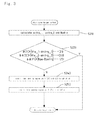
- Fig. 2 is a flow chart of a control flow of the engine 100 according to a first embodiment of the present invention.
- Fig. 3 is a flow chart of a control flow of the engine 100 according to a second embodiment of the present invention.
- the engine 100 according to the present invention is a direct injection type 6-cylindered engine and mainly includes an intake manifold 30 to which a first intake path 3 and a second intake path 4 are connected, two exhaust manifolds 40 to which a first exhaust path 41 and a second exhaust path 42 are connected, and a common rail type fuel injection device (hereinafter, referred to as fuel injection device) 8.
- fuel injection device a common rail type fuel injection device
- the engine 100 includes a variable parallel supercharging system 9 having a first supercharger 10 and a second supercharger 20.
- the first supercharger 10 includes a turbine 12 rotationally driven by receiving exhaust gas flowing in the first exhaust path 41 and a compressor 11 rotationally driven by the turbine 12 so as to compress intake air flowing in the first intake path 3.
- the second supercharger 20 includes a turbine 22 rotationally driven by receiving exhaust gas flowing in the second exhaust path 42 and a compressor 21 rotationally driven by the turbine 22 so as to compress intake air flowing in the first intake path 4.
- the capacity of the second supercharger 20 is larger than that of the first supercharger 10 at the normal operation state.
- Each of the first supercharger 10 and the second supercharger 20 is a variable capacity type supercharger.
- the first supercharger 10 has a first variable actuator 14, and the second supercharger 20 has a second variable actuator 24.
- the first variable actuator 14 controls vane opening degree of a variable vane 13 provided in the turbine 12 of the first supercharger 10.
- the second variable actuator 24 controls vane opening degree of a variable vane 23 provided in the turbine 22 of the second supercharger 20.
- the first supercharger 10 and the second supercharger 20 control the vane opening degree by the variable actuators 14 and 24. Accordingly, flow rate of exhaust gas introduced into the turbines 12 and 22 can be controlled suitably, whereby supercharging efficiency is improved in wide drive range.
- the capacity of the second supercharger 20 is larger than that of the first supercharger 10 at the normal operation state.
- the second supercharger 20 acts as a supercharger whose capacity is the same as that of the first supercharger 10.
- the compressor 11 of the first supercharger 10 and an intercooler 31 cooling intake air compressed in the compressor 11 are arranged in the first intake path 3.
- the compressor 21 of the second supercharger 20 and an intercooler 32 cooling intake air compressed in the compressor 21 are arranged in the second intake path 4.
- Each of the exhaust manifolds 40 discharges exhaust gas from the three cylinders.
- the turbine 12 of the first supercharger 10 is arranged in the first exhaust path 41.
- the turbine 22 of the second supercharger 20 is arranged in the second exhaust path 42.
- a bypass path 5 connects the part of the first exhaust path 41 upstream the turbine 12 of the first supercharger 10 to the part of the second exhaust path 42 upstream the turbine 22 of the second supercharger 20.
- a bypasses flow rate control valve 25 which controls flow rate of exhaust gas passing through the bypass path 5 is provided in the bypass path 5.
- a control device 60 mainly includes a central processing unit and a storage device.
- the control device 60 is electrically connected through an amplifier 65 to a first supercharger rotation sensor 61 provided in the first supercharger 10 and a second supercharger rotation sensor 62 provided in the second supercharger 20.
- the control device 60 is electrically connected to a supercharging pressure sensor 63 provided in the intake manifold 30 and the other sensors, forms control signals based on electric signals from the sensors, and outputs the control signals to the first variable actuator 14, the second variable actuator 24 and the like.
- control of the variable vane 13 of the first supercharger 10 the control of the variable vane 23 of the second supercharger 20, and the control of valve opening degree of the bypasses flow rate control valve 25 by the control device 60 are defined as supercharger control.
- the control device 60 controls the variable vane 13 of the first supercharger 10 and the variable vane 23 of the second supercharger 20 so as to make the first supercharger 10 and the second supercharger 20 have the same capacity and to enable the first supercharger 10 and the second supercharger 20 to compress intake air the most efficiently in the case that the driving state of the engine 100 is at low speed rotation and low load state, that is, at low output driving state.
- the control device 60 calculates a target supercharger rotation speed ⁇ ctrg and a target supercharging pressure Bpatrg (S110).
- the target supercharger rotation speed ⁇ ctrg is the rotation speed of the compressors 11 and 12 at which intake air can be compressed the most efficiently in the first supercharger 10 and the second supercharger 20, and is calculated based on the target supercharging pressure Bpatrg, a map stored in the storage device of the control device 60 and the like.
- the target supercharging pressure Bpatrg is the supercharging pressure at which fuel combustion following the driving state of the engine 100 can be optimized, and is calculated based on a map stored in the storage device of the control device 60 and the like.
- the control device 60 judges as condition (11) whether the absolute value of the difference between a first supercharger rotation speed Nta_1 detected by the first supercharger rotation sensor 61 and the target supercharger rotation speed ⁇ ctrg is smaller than a predetermined value ⁇ 11, judges as condition (12) whether the absolute value of the difference between a second supercharger rotation speed Nta_2 detected by the second supercharger rotation sensor 62 and the target supercharger rotation speed ⁇ ctrg is smaller than a predetermined value ⁇ 12, and judges as condition (13) whether a supercharging pressure Bpa detected by a supercharging pressure sensor 63 and the target supercharging pressure Bpatrg is smaller than a predetermined value ⁇ 13 (S120).
- the control device 60 judges that each of the first supercharger rotation speed Nta_1 and the second supercharger rotation speed Nta_2 is the supercharger rotation speed of the variable parallel supercharging system 9 at which intake air can be compressed the most efficiently and the supercharging pressure Bpa is the most suitable supercharging pressure to the fuel combustion.
- the control device 60 judges that the first supercharger rotation speed Nta_1 or the second supercharger rotation speed Nta_2 is not the supercharger rotation speed of the variable parallel supercharging system 9 at which intake air can be compressed the most efficiently or that the supercharging pressure Bpa is not the most suitable supercharging pressure to the fuel combustion.
- control device 60 controls the variable vane 13 of the first supercharger 10 so as to control the vane opening degree until the condition (11) is satisfied, and controls the variable vane 23 of the second supercharger 20 so as to control the vane opening degree until the condition (12) is satisfied (S140). Subsequently, the control device 60 controls the variable vane 13 of the first supercharger 10 and the variable vane 23 of the second supercharger 20 so as to control the vane opening degree until the condition (13) is satisfied (S150).
- variable vane 13 of the first supercharger 10 and the variable vane 23 of the second supercharger 20 are controlled while employing the first supercharger rotation speed Nta_1, the second supercharger rotation speed Nta_2 and the supercharging pressure Bpa as feedback values, whereby the variable parallel supercharging system 9 can be controlled accurately.
- the control device 60 controls valve opening degree of the bypasses flow rate control valve 25 so as to realize the most suitable supercharging pressure for fuel combustion while the second supercharger 20 is set at the supercharger rotation speed at which intake air can be compressed efficiency.
- the control device 60 calculates a target first supercharger rotation speed ⁇ ctrg_1, a target second supercharger rotation speed ⁇ ctrg_2 and a target supercharging pressure Bpatrg(S210).
- the target first supercharger rotation speed ⁇ ctrg_1 is the rotation speed of the compressor 11 at which intake air can be compressed the most efficiently in the first supercharger 10, and is calculated based on the target supercharging pressure Bpatrg, a map stored in the storage device of the control device 60 and the like.
- the target second supercharger rotation speed ⁇ ctrg_2 is the rotation speed of the compressor 21 at which intake air can be compressed the most efficiently in the second supercharger 20, and is calculated based on the target supercharging pressure Bpatrg, a map stored in the storage device of the control device 60 and the like.
- the target supercharging pressure Bpatrg is the supercharging pressure at which fuel combustion following the driving state of the engine 100 can be optimized, and is calculated based on a map stored in the storage device of the control device 60 and the like.
- the control device 60 judges as condition (21) whether the absolute value of the difference between a first supercharger rotation speed Nta_1 detected by the first supercharger rotation sensor 61 and target first supercharger rotation speed ⁇ ctrg_1 is smaller than a predetermined value ⁇ 21, judges as condition (22) whether the absolute value of the difference between a second supercharger rotation speed Nta_2 detected by the second supercharger rotation sensor 62 and target second supercharger rotation speed ⁇ ctrg_2 is smaller than a predetermined value ⁇ 22, and judges as condition (23) whether a supercharging pressure Bpa detected by the supercharging pressure sensor 63 and the target supercharging pressure Bpatrg is smaller than a predetermined value ⁇ 23 (S220).
- the control device 60 judges that each of the first supercharger rotation speed Nta_1 and the second supercharger rotation speed Nta_2 is the supercharger rotation speed at which intake air can be compressed the most efficiently in the variable parallel supercharging system 9 and the supercharging pressure Bpa is the most suitable supercharging pressure to the fuel combustion.
- the control device 60 judges that the first supercharger rotation speed Nta_1 or the second supercharger rotation speed Nta_2 is not the supercharger rotation speed of the variable parallel supercharging system 9 at which intake air can be compressed the most efficiently or that the supercharging pressure Bpa is not the most suitable supercharging pressure to the fuel combustion.
- control device 60 controls the bypasses flow rate control valve 25 so as to control the vane opening degree until the conditions (21) and (22) are satisfied (S240). Subsequently, the control device 60 controls the bypasses flow rate control valve 25 so as to control the vane opening degree until the condition (23) is satisfied (S250).
- variable vane 13 of the first supercharger 10 the variable vane 23 of the second supercharger 20 and the bypasses flow rate control valve 25 are controlled while employing the first supercharger rotation speed Nta_1, the second supercharger rotation speed Nta_2 and the supercharging pressure Bpa as feedback values, whereby the variable parallel supercharging system 9 can be controlled accurately further.
- the first supercharger rotation speed Nta_1 directly concerned with the action of the first supercharger 10 and the second supercharger rotation speed Nta_2 directly concerned with the action of the second supercharger 20 are employed as the feedback values, whereby the action can be switched accurately between two action patterns, i.e., the pattern that the first supercharger 10 and the second supercharger 20 having different capacities are actuated as having the same capacity and the pattern that the first supercharger 10 and the second supercharger 20 are actuated as having different capacities corresponding to the driving state of the engine 100.
- the overspeed of the first supercharger 10 can be prevented by increasing the valve opening degree of the bypasses flow rate control valve 25. Furthermore, by employing the supercharger rotation speed as the feedback value, whereby accurate control can be performed without considering dispersion of products of the first supercharger 10 and the second supercharger 20.
- the present invention can be employed for an engine having a variable parallel supercharging system.
Abstract
Description
- The present invention relates to an art of control of an engine having a variable parallel supercharging system.
- Conventionally, a supercharging system is known in which two superchargers are arranged about one engine. For example, in a parallel supercharging system, two superchargers compress intake air flowing in two intake paths. In a series supercharging system, two superchargers compress intake air flowing in one intake path. The
Patent Literature 1 discloses an engine having a so-called sequential twin turbo which is a form of the series supercharging system. - A supercharger of variable capacity type is also known in which exhaust gas is introduced to a turbine constituting the supercharger while controlling flow rate suitably so as to improve supercharging efficiency. A parallel supercharging system in which two superchargers compress intake air flowing in two intake paths and at least one of the superchargers is variable capacity type is defined as a variable parallel supercharging system.
- Conventionally, in control of capacity in a variable capacity type supercharger, feedback control is performed with supercharging pressure detected by a supercharging pressure sensor. However, the supercharging pressure is indirect physical quantity about the action of the supercharger and is disadvantageous because the control of capacity of the supercharger cannot be performed accurately. Especially, the variable parallel supercharging system having the variable capacity type superchargers is disadvantageous because the control of capacity cannot be performed accurately further.
Patent Literature 1: the Japanese Patent Laid Open GazetteHei. 5-288111 - Then, the purpose of the present invention is to provide an engine and a control method which can control accurately a variable parallel supercharging system.
- Explanation will be given on means of the present invention for solving the problems.
- According to the first aspect of the present invention, an engine in which intake air distributed to cylinders is supplied through a first intake path and a second intake path, and exhaust gas collected from the cylinders is discharged through a first exhaust path and a second exhaust path, includes a variable parallel supercharging system comprising a first supercharger which is driven by exhaust gas flowing in a first exhaust path and pressurizes intake air flowing in a first intake path, and a second supercharger which is driven by exhaust gas flowing in a second exhaust path and pressurizes intake air flowing in a second intake air route, a supercharging pressure sensor detecting pressure of the intake air pressurized by the first supercharger and the second supercharger, a first supercharger rotation sensor detecting supercharger rotational speed of the first supercharger, a second supercharger rotation sensor detecting supercharger rotational speed of the second supercharger, a first variable actuator controlling capacity of the first supercharger, a second variable actuator controlling capacity of the second supercharger, and a control device enabling the first variable actuator and the second variable actuator to be controlled. The control device controls the first variable actuator based on detection signals from the supercharging pressure sensor and the first supercharger rotation sensor, and controls the second variable actuator based on detection signals from the supercharging pressure sensor and the second supercharger rotation sensor.
- According to the second aspect of the present invention, the engine according to the first aspect further includes a bypass path connecting the part of the first exhaust path upstream the first supercharger to the part of the second exhaust path upstream the second supercharger, a bypasses flow rate control valve controlling flow rate of exhaust gas flowing in the bypass path, and a control device enabling the first variable actuator, the second variable actuator and the bypasses flow rate control valve to be controlled. The control device controls the first variable actuator based on detection signals from the supercharging pressure sensor and the first supercharger rotation sensor, controls the second variable actuator based on detection signals from the supercharging pressure sensor and the second supercharger rotation sensor, and controls the bypasses flow rate control valve based on detection signals from the supercharging pressure sensor, the first supercharger rotation sensor and the second supercharger rotation sensor.
- The present invention constructed as the above brings the following effects.
- According to the first aspect of the present invention, the capacity of the supercharger is controlled while employing the supercharging pressure and the supercharger rotation speed as feedback values, whereby the variable parallel supercharging system can be controlled accurately.
- According to the second aspect of the present invention, the capacity of the supercharger is controlled and the vane opening degree of the bypasses flow rate control valve is controlled while employing the supercharging pressure and the supercharger rotation speed as feedback values, whereby the variable parallel supercharging system can be controlled accurately further.
-
- [
Fig. 1 ] It is a schematic drawing of entire construction of an engine according to the present invention. - [
Fig. 2 ] It is a flow chart of a control flow of the engine according to a first embodiment of the present invention. - [
Fig. 3 ] It is a flow chart of a control flow of the engine according to a second embodiment of the present invention. -
- 3
- first intake path
- 4
- second intake path
- 5
- bypass path
- 9
- variable parallel supercharging system
- 10
- first supercharger
- 11
- compressor
- 12
- turbine
- 13
- variable vane
- 14
- first variable actuator
- 20
- second supercharger
- 21
- compressor
- 22
- turbine
- 23
- variable vane
- 24
- second variable actuator
- 25
- bypasses flow rate control valve
- 30
- intake manifold
- 40
- exhaust manifold
- 41
- first exhaust path
- 42
- second exhaust path
- 61
- first supercharger rotation sensor
- 62
- second supercharger rotation sensor
- 63
- supercharging pressure sensor
- 100
- engine
- Bpa
- supercharging pressure
- Bpatrg
- target supercharging pressure
- ωctrg
- target supercharger rotation speed
- Nta_1
- first supercharger rotation speed
- ωctrg_1
- target first supercharger rotation speed
- Nta_2
- second supercharger rotation speed
- ωctrg_2
- target second supercharger rotation speed
- Next, explanation will be given on the embodiments of the present invention.
-
Fig. 1 is a schematic drawing of entire construction of anengine 100 according to the present invention.Fig. 2 is a flow chart of a control flow of theengine 100 according to a first embodiment of the present invention.Fig. 3 is a flow chart of a control flow of theengine 100 according to a second embodiment of the present invention. - Firstly, explanation will be given on the
engine 100 according to the present invention. Theengine 100 according to the present invention is a direct injection type 6-cylindered engine and mainly includes anintake manifold 30 to which afirst intake path 3 and a second intake path 4 are connected, two exhaust manifolds 40 to which afirst exhaust path 41 and a second exhaust path 42 are connected, and a common rail type fuel injection device (hereinafter, referred to as fuel injection device) 8. - The
engine 100 includes a variable parallel supercharging system 9 having a first supercharger 10 and a second supercharger 20. The first supercharger 10 includes aturbine 12 rotationally driven by receiving exhaust gas flowing in thefirst exhaust path 41 and acompressor 11 rotationally driven by theturbine 12 so as to compress intake air flowing in thefirst intake path 3. The second supercharger 20 includes aturbine 22 rotationally driven by receiving exhaust gas flowing in the second exhaust path 42 and acompressor 21 rotationally driven by theturbine 22 so as to compress intake air flowing in the first intake path 4. The capacity of the second supercharger 20 is larger than that of the first supercharger 10 at the normal operation state. - Each of the first supercharger 10 and the second supercharger 20 is a variable capacity type supercharger. The first supercharger 10 has a first variable actuator 14, and the second supercharger 20 has a second variable actuator 24. The first variable actuator 14 controls vane opening degree of a
variable vane 13 provided in theturbine 12 of the first supercharger 10. The second variable actuator 24 controls vane opening degree of avariable vane 23 provided in theturbine 22 of the second supercharger 20. - The first supercharger 10 and the second supercharger 20 control the vane opening degree by the variable actuators 14 and 24. Accordingly, flow rate of exhaust gas introduced into the
turbines - In the variable parallel supercharging system 9 of the
engine 100 according to the present invention, the capacity of the second supercharger 20 is larger than that of the first supercharger 10 at the normal operation state. However, by controlling the vane opening degree of thevariable vane 23 so as to reduce the capacity, the second supercharger 20 acts as a supercharger whose capacity is the same as that of the first supercharger 10. - In the
first intake path 3, from the upstream side toward theintake manifold 30, thecompressor 11 of the first supercharger 10 and anintercooler 31 cooling intake air compressed in thecompressor 11 are arranged. In the second intake path 4, from the upstream side toward theintake manifold 30, thecompressor 21 of the second supercharger 20 and anintercooler 32 cooling intake air compressed in thecompressor 21 are arranged. - Each of the exhaust manifolds 40 discharges exhaust gas from the three cylinders. In the
first exhaust path 41, from one of the exhaust manifolds 40 toward the downstream side, theturbine 12 of the first supercharger 10 is arranged. In the second exhaust path 42, from the other exhaust manifold 40 toward the downstream side, theturbine 22 of the second supercharger 20 is arranged. - A
bypass path 5 connects the part of thefirst exhaust path 41 upstream theturbine 12 of the first supercharger 10 to the part of the second exhaust path 42 upstream theturbine 22 of the second supercharger 20. A bypasses flow rate control valve 25 which controls flow rate of exhaust gas passing through thebypass path 5 is provided in thebypass path 5. - A control device 60 mainly includes a central processing unit and a storage device. The control device 60 is electrically connected through an amplifier 65 to a first
supercharger rotation sensor 61 provided in the first supercharger 10 and a second supercharger rotation sensor 62 provided in the second supercharger 20. The control device 60 is electrically connected to a supercharging pressure sensor 63 provided in theintake manifold 30 and the other sensors, forms control signals based on electric signals from the sensors, and outputs the control signals to the first variable actuator 14, the second variable actuator 24 and the like. Hereinafter, the control of thevariable vane 13 of the first supercharger 10, the control of thevariable vane 23 of the second supercharger 20, and the control of valve opening degree of the bypasses flow rate control valve 25 by the control device 60 are defined as supercharger control. - Explanation will be given on the supercharger control of the
engine 100 according to the first embodiment of the present invention referring toFig. 2 . The control device 60 controls thevariable vane 13 of the first supercharger 10 and thevariable vane 23 of the second supercharger 20 so as to make the first supercharger 10 and the second supercharger 20 have the same capacity and to enable the first supercharger 10 and the second supercharger 20 to compress intake air the most efficiently in the case that the driving state of theengine 100 is at low speed rotation and low load state, that is, at low output driving state. - Firstly, the control device 60 calculates a target supercharger rotation speed ωctrg and a target supercharging pressure Bpatrg (S110).
The target supercharger rotation speed ωctrg is the rotation speed of thecompressors
The target supercharging pressure Bpatrg is the supercharging pressure at which fuel combustion following the driving state of theengine 100 can be optimized, and is calculated based on a map stored in the storage device of the control device 60 and the like. - The control device 60 judges as condition (11) whether the absolute value of the difference between a first supercharger rotation speed Nta_1 detected by the first
supercharger rotation sensor 61 and the target supercharger rotation speed ωctrg is smaller than a predetermined value α11, judges as condition (12) whether the absolute value of the difference between a second supercharger rotation speed Nta_2 detected by the second supercharger rotation sensor 62 and the target supercharger rotation speed ωctrg is smaller than a predetermined value α12, and judges as condition (13) whether a supercharging pressure Bpa detected by a supercharging pressure sensor 63 and the target supercharging pressure Bpatrg is smaller than a predetermined value α13 (S120). - In the case that the conditions (11), (12) and (13) are satisfied at S120, the control device 60 judges that each of the first supercharger rotation speed Nta_1 and the second supercharger rotation speed Nta_2 is the supercharger rotation speed of the variable parallel supercharging system 9 at which intake air can be compressed the most efficiently and the supercharging pressure Bpa is the most suitable supercharging pressure to the fuel combustion.
- On the other hand, in the case that the condition (11), (12) or (13) is not satisfied at S120, the control device 60 judges that the first supercharger rotation speed Nta_1 or the second supercharger rotation speed Nta_2 is not the supercharger rotation speed of the variable parallel supercharging system 9 at which intake air can be compressed the most efficiently or that the supercharging pressure Bpa is not the most suitable supercharging pressure to the fuel combustion.
- Then, the control device 60 controls the
variable vane 13 of the first supercharger 10 so as to control the vane opening degree until the condition (11) is satisfied, and controls thevariable vane 23 of the second supercharger 20 so as to control the vane opening degree until the condition (12) is satisfied (S140). Subsequently, the control device 60 controls thevariable vane 13 of the first supercharger 10 and thevariable vane 23 of the second supercharger 20 so as to control the vane opening degree until the condition (13) is satisfied (S150). - As mentioned above, the
variable vane 13 of the first supercharger 10 and thevariable vane 23 of the second supercharger 20 are controlled while employing the first supercharger rotation speed Nta_1, the second supercharger rotation speed Nta_2 and the supercharging pressure Bpa as feedback values, whereby the variable parallel supercharging system 9 can be controlled accurately. - Explanation will be given on the supercharger control of the
engine 100 according to the second embodiment of the present invention referring toFig. 3 . In the case that the driving state of theengine 100 shifts from the low output driving state to the high output driving state and the first supercharger 10 reaches the maximum of the supercharger rotation speed at which intake air can be compressed efficiency, the control device 60 controls valve opening degree of the bypasses flow rate control valve 25 so as to realize the most suitable supercharging pressure for fuel combustion while the second supercharger 20 is set at the supercharger rotation speed at which intake air can be compressed efficiency. - Firstly, the control device 60 calculates a target first supercharger rotation speed ωctrg_1, a target second supercharger rotation speed ωctrg_2 and a target supercharging pressure Bpatrg(S210).
The target first supercharger rotation speed ωctrg_1 is the rotation speed of thecompressor 11 at which intake air can be compressed the most efficiently in the first supercharger 10, and is calculated based on the target supercharging pressure Bpatrg, a map stored in the storage device of the control device 60 and the like.
The target second supercharger rotation speed ωctrg_2 is the rotation speed of thecompressor 21 at which intake air can be compressed the most efficiently in the second supercharger 20, and is calculated based on the target supercharging pressure Bpatrg, a map stored in the storage device of the control device 60 and the like.
The target supercharging pressure Bpatrg is the supercharging pressure at which fuel combustion following the driving state of theengine 100 can be optimized, and is calculated based on a map stored in the storage device of the control device 60 and the like. - The control device 60 judges as condition (21) whether the absolute value of the difference between a first supercharger rotation speed Nta_1 detected by the first
supercharger rotation sensor 61 and target first supercharger rotation speed ωctrg_1 is smaller than a predetermined value α21, judges as condition (22) whether the absolute value of the difference between a second supercharger rotation speed Nta_2 detected by the second supercharger rotation sensor 62 and target second supercharger rotation speed ωctrg_2 is smaller than a predetermined value α22, and judges as condition (23) whether a supercharging pressure Bpa detected by the supercharging pressure sensor 63 and the target supercharging pressure Bpatrg is smaller than a predetermined value α23 (S220). - In the case that the conditions (21), (22) and (23) are satisfied at S220, the control device 60 judges that each of the first supercharger rotation speed Nta_1 and the second supercharger rotation speed Nta_2 is the supercharger rotation speed at which intake air can be compressed the most efficiently in the variable parallel supercharging system 9 and the supercharging pressure Bpa is the most suitable supercharging pressure to the fuel combustion.
- On the other hand, in the case that the condition (21), (22) or (23) is not satisfied at S220, the control device 60 judges that the first supercharger rotation speed Nta_1 or the second supercharger rotation speed Nta_2 is not the supercharger rotation speed of the variable parallel supercharging system 9 at which intake air can be compressed the most efficiently or that the supercharging pressure Bpa is not the most suitable supercharging pressure to the fuel combustion.
- Then, the control device 60 controls the bypasses flow rate control valve 25 so as to control the vane opening degree until the conditions (21) and (22) are satisfied (S240). Subsequently, the control device 60 controls the bypasses flow rate control valve 25 so as to control the vane opening degree until the condition (23) is satisfied (S250).
- As mentioned above, the
variable vane 13 of the first supercharger 10, thevariable vane 23 of the second supercharger 20 and the bypasses flow rate control valve 25 are controlled while employing the first supercharger rotation speed Nta_1, the second supercharger rotation speed Nta_2 and the supercharging pressure Bpa as feedback values, whereby the variable parallel supercharging system 9 can be controlled accurately further. - The first supercharger rotation speed Nta_1 directly concerned with the action of the first supercharger 10 and the second supercharger rotation speed Nta_2 directly concerned with the action of the second supercharger 20 are employed as the feedback values, whereby the action can be switched accurately between two action patterns, i.e., the pattern that the first supercharger 10 and the second supercharger 20 having different capacities are actuated as having the same capacity and the pattern that the first supercharger 10 and the second supercharger 20 are actuated as having different capacities corresponding to the driving state of the
engine 100. - In the case that the supercharger rotation speed is larger than the maximum value of the first supercharger 10 having small capacity, the overspeed of the first supercharger 10 can be prevented by increasing the valve opening degree of the bypasses flow rate control valve 25. Furthermore, by employing the supercharger rotation speed as the feedback value, whereby accurate control can be performed without considering dispersion of products of the first supercharger 10 and the second supercharger 20.
- The present invention can be employed for an engine having a variable parallel supercharging system.
Claims (2)
- An engine in which intake air distributed to cylinders is supplied through a first intake path and a second intake path, and exhaust gas collected from the cylinders is discharged through a first exhaust path and a second exhaust path, comprising:a variable parallel supercharging system comprising a first supercharger which is driven by exhaust gas flowing in a first exhaust path and pressurizes intake air flowing in a first intake path, and a second supercharger which is driven by exhaust gas flowing in a second exhaust path and pressurizes intake air flowing in a second intake air route;a supercharging pressure sensor detecting pressure of the intake air pressurized by the first supercharger and the second supercharger;a first supercharger rotation sensor detecting supercharger rotational speed of the first supercharger;a second supercharger rotation sensor detecting supercharger rotational speed of the second supercharger;a first variable actuator controlling capacity of the first supercharger;a second variable actuator controlling capacity of the second supercharger; anda control device enabling the first variable actuator and the second variable actuator to be controlled,characterized in thatthe control device controls the first variable actuator based on detection signals from the supercharging pressure sensor and the first supercharger rotation sensor, and controls the second variable actuator based on detection signals from the supercharging pressure sensor and the second supercharger rotation sensor.
- The engine according to claim 1, further comprising:a bypass path connecting the part of the first exhaust path upstream the first supercharger to the part of the second exhaust path upstream the second supercharger;a bypasses flow rate control valve controlling flow rate of exhaust gas flowing in the bypass path; anda control device enabling the first variable actuator, the second variable actuator and the bypasses flow rate control valve to be controlled,wherein the control device controls the first variable actuator based on detection signals from the supercharging pressure sensor and the first supercharger rotation sensor, controls the second variable actuator based on detection signals from the supercharging pressure sensor and the second supercharger rotation sensor, and controls the bypasses flow rate control valve based on detection signals from the supercharging pressure sensor, the first supercharger rotation sensor and the second supercharger rotation sensor.
Applications Claiming Priority (2)
| Application Number | Priority Date | Filing Date | Title |
|---|---|---|---|
| JP2008260867A JP5331435B2 (en) | 2008-10-07 | 2008-10-07 | engine |
| PCT/JP2009/066247 WO2010041545A1 (en) | 2008-10-07 | 2009-09-17 | Engine |
Publications (2)
| Publication Number | Publication Date |
|---|---|
| EP2333274A1 true EP2333274A1 (en) | 2011-06-15 |
| EP2333274A4 EP2333274A4 (en) | 2014-05-28 |
Family
ID=42100499
Family Applications (1)
| Application Number | Title | Priority Date | Filing Date |
|---|---|---|---|
| EP09819080.4A Ceased EP2333274A4 (en) | 2008-10-07 | 2009-09-17 | Engine |
Country Status (6)
| Country | Link |
|---|---|
| US (1) | US8857176B2 (en) |
| EP (1) | EP2333274A4 (en) |
| JP (1) | JP5331435B2 (en) |
| CN (1) | CN102177322B (en) |
| BR (1) | BRPI0920864A2 (en) |
| WO (1) | WO2010041545A1 (en) |
Cited By (2)
| Publication number | Priority date | Publication date | Assignee | Title |
|---|---|---|---|---|
| DE102015107532A1 (en) | 2015-05-13 | 2016-11-17 | Dr. Ing. H.C. F. Porsche Aktiengesellschaft | Internal combustion engine |
| CN106917671A (en) * | 2015-12-24 | 2017-07-04 | 三菱电机株式会社 | The control device of internal combustion engine and the control method of internal combustion engine |
Families Citing this family (8)
| Publication number | Priority date | Publication date | Assignee | Title |
|---|---|---|---|---|
| JP5164737B2 (en) * | 2008-08-19 | 2013-03-21 | ヤンマー株式会社 | engine |
| CN102317593A (en) * | 2009-02-26 | 2012-01-11 | 博格华纳公司 | Internal combustion engine |
| DE102012211425A1 (en) * | 2012-07-02 | 2014-01-23 | Robert Bosch Gmbh | Method for determining a speed of a compressor |
| US9151217B2 (en) * | 2012-12-21 | 2015-10-06 | Ford Global Technologies, Llc | Twin turbocharger wastegate control |
| IL241683B (en) | 2015-09-17 | 2020-09-30 | Israel Aerospace Ind Ltd | Multistage turbocharging system |
| CN110318864B (en) * | 2018-03-29 | 2020-07-28 | 潍柴动力股份有限公司 | Altitude-based two-stage supercharging system opening correction method and two-stage supercharging system |
| US11022028B2 (en) * | 2019-05-07 | 2021-06-01 | Caterpillar Inc. | Engine system and method including first and second turbochargers |
| CN111663994A (en) * | 2020-06-17 | 2020-09-15 | 中车大连机车研究所有限公司 | Control method of adjustable nozzle |
Citations (10)
| Publication number | Priority date | Publication date | Assignee | Title |
|---|---|---|---|---|
| EP0352064A1 (en) * | 1988-07-18 | 1990-01-24 | Isuzu Ceramics Research Institute Co., Ltd. | Drive system for turbochargers with rotary electric machines |
| US6357234B1 (en) * | 2000-09-21 | 2002-03-19 | Caterpillar Inc. | Turbocharger system with turbines having independently controlled variable nozzles |
| US20020103593A1 (en) * | 2001-01-31 | 2002-08-01 | Brackney Larry J. | System for managing charge flow and egr fraction in an internal combustion engine |
| US6550247B1 (en) * | 2001-08-30 | 2003-04-22 | Caterpillar Inc | Multiple parallel turbocharger control with discrete step nozzles |
| GB2406394A (en) * | 2003-09-29 | 2005-03-30 | Detroit Diesel Corp | Methods for responding to sensor failures on EGR/VGT engines |
| US20060021347A1 (en) * | 2004-07-28 | 2006-02-02 | Ford Global Technologies, Llc | Series/parallel turbochargers and switchable high/low pressure egr for internal combustion engines |
| US7089738B1 (en) * | 2005-04-09 | 2006-08-15 | Cummins, Inc. | System for controlling turbocharger compressor surge |
| US20070068158A1 (en) * | 2005-09-28 | 2007-03-29 | Harold Sun | System and method for reducing surge |
| US20070151243A1 (en) * | 2005-12-30 | 2007-07-05 | Honeywell International Inc. | Control of dual stage turbocharging |
| EP1927739A1 (en) * | 2006-12-01 | 2008-06-04 | Ford Global Technologies, LLC | Method and device for controlling a turbocharging system |
Family Cites Families (21)
| Publication number | Priority date | Publication date | Assignee | Title |
|---|---|---|---|---|
| US4556038A (en) * | 1983-03-04 | 1985-12-03 | Aisin Seiki Kabushiki Kaisha | Supercharged internal combustion engine having control means responsive to engine speed and accelerator pedal velocity |
| JPS60178329A (en) | 1984-02-27 | 1985-09-12 | Sumitomo Electric Ind Ltd | Optical fiber type temperature detector |
| JPS60178329U (en) * | 1984-05-08 | 1985-11-27 | トヨタ自動車株式会社 | Exhaust system structure of multi-cylinder internal combustion engine |
| CH658884A5 (en) * | 1984-10-01 | 1986-12-15 | Cerac Inst Sa | INTERNAL COMBUSTION ENGINE UNIT. |
| DE3512281A1 (en) * | 1985-04-03 | 1986-10-16 | Karl-Nikolaus Dr. 8000 München Regar | METHOD FOR OPERATING AN INTERNAL COMBUSTION ENGINE AND CARRYING OUT THIS METHOD OF TRAINED INTERNAL COMBUSTION ENGINE |
| US4730457A (en) * | 1985-10-29 | 1988-03-15 | Fuji Jukogyo Kabushiki Kaisha | Supercharging system for automotive engines |
| US5187935A (en) * | 1988-12-26 | 1993-02-23 | Honda Giken Kogyo Kabushiki Kaisha | Engine control device |
| SE467634B (en) * | 1990-05-15 | 1992-08-17 | Volvo Ab | TOUR REGULATION DEVICE |
| JP3320765B2 (en) * | 1992-04-03 | 2002-09-03 | 富士重工業株式会社 | Air-fuel ratio control method for sequential turbo engine |
| JP3311866B2 (en) * | 1994-07-22 | 2002-08-05 | ヤンマーディーゼル株式会社 | Two-stage supercharged engine |
| SE506125C2 (en) * | 1994-12-08 | 1997-11-10 | Scania Cv Ab | Arrangements for redirecting exhaust gases in supercharged engines with parallel turbines |
| SE506130C2 (en) * | 1994-12-08 | 1997-11-10 | Scania Cv Ab | Arrangements for redirecting exhaust gases in supercharged engines with serial turbines |
| JP2001115822A (en) * | 1999-10-19 | 2001-04-24 | Hino Motors Ltd | Particulate filter regenerating device for diesel engine |
| JP3937791B2 (en) * | 2001-10-15 | 2007-06-27 | 日産自動車株式会社 | Control device for multi-cylinder diesel engine |
| US7353102B2 (en) * | 2004-05-06 | 2008-04-01 | Kabushiki Kaisha Toyota Jidoshokki | Trouble diagnosis apparatus for supercharger of internal combustion engine |
| EP1640597B1 (en) * | 2004-09-22 | 2008-07-23 | Ford Global Technologies, LLC | Supercharged internal combustion engine and method for operating such an internal combustion engine |
| EP1640595A1 (en) * | 2004-09-22 | 2006-03-29 | Ford Global Technologies, LLC, A subsidary of Ford Motor Company | Supercharged internal combustion engine and method of operating such an internal combustion engine |
| JP4635793B2 (en) * | 2005-09-15 | 2011-02-23 | トヨタ自動車株式会社 | Supercharging system for internal combustion engines |
| JP2008008202A (en) * | 2006-06-29 | 2008-01-17 | Hino Motors Ltd | Turbine protection device |
| GB0615143D0 (en) * | 2006-07-29 | 2006-09-06 | Cummins Turbo Tech Ltd | Multi-stage turbocharger system |
| JP2008190412A (en) * | 2007-02-05 | 2008-08-21 | Toyota Motor Corp | Supercharger control device for internal combustion engine |
-
2008
- 2008-10-07 JP JP2008260867A patent/JP5331435B2/en not_active Expired - Fee Related
-
2009
- 2009-09-17 WO PCT/JP2009/066247 patent/WO2010041545A1/en active Application Filing
- 2009-09-17 BR BRPI0920864A patent/BRPI0920864A2/en not_active IP Right Cessation
- 2009-09-17 US US13/123,126 patent/US8857176B2/en not_active Expired - Fee Related
- 2009-09-17 EP EP09819080.4A patent/EP2333274A4/en not_active Ceased
- 2009-09-17 CN CN2009801395284A patent/CN102177322B/en not_active Expired - Fee Related
Patent Citations (10)
| Publication number | Priority date | Publication date | Assignee | Title |
|---|---|---|---|---|
| EP0352064A1 (en) * | 1988-07-18 | 1990-01-24 | Isuzu Ceramics Research Institute Co., Ltd. | Drive system for turbochargers with rotary electric machines |
| US6357234B1 (en) * | 2000-09-21 | 2002-03-19 | Caterpillar Inc. | Turbocharger system with turbines having independently controlled variable nozzles |
| US20020103593A1 (en) * | 2001-01-31 | 2002-08-01 | Brackney Larry J. | System for managing charge flow and egr fraction in an internal combustion engine |
| US6550247B1 (en) * | 2001-08-30 | 2003-04-22 | Caterpillar Inc | Multiple parallel turbocharger control with discrete step nozzles |
| GB2406394A (en) * | 2003-09-29 | 2005-03-30 | Detroit Diesel Corp | Methods for responding to sensor failures on EGR/VGT engines |
| US20060021347A1 (en) * | 2004-07-28 | 2006-02-02 | Ford Global Technologies, Llc | Series/parallel turbochargers and switchable high/low pressure egr for internal combustion engines |
| US7089738B1 (en) * | 2005-04-09 | 2006-08-15 | Cummins, Inc. | System for controlling turbocharger compressor surge |
| US20070068158A1 (en) * | 2005-09-28 | 2007-03-29 | Harold Sun | System and method for reducing surge |
| US20070151243A1 (en) * | 2005-12-30 | 2007-07-05 | Honeywell International Inc. | Control of dual stage turbocharging |
| EP1927739A1 (en) * | 2006-12-01 | 2008-06-04 | Ford Global Technologies, LLC | Method and device for controlling a turbocharging system |
Non-Patent Citations (1)
| Title |
|---|
| See also references of WO2010041545A1 * |
Cited By (3)
| Publication number | Priority date | Publication date | Assignee | Title |
|---|---|---|---|---|
| DE102015107532A1 (en) | 2015-05-13 | 2016-11-17 | Dr. Ing. H.C. F. Porsche Aktiengesellschaft | Internal combustion engine |
| DE102015107532B4 (en) | 2015-05-13 | 2022-10-06 | Dr. Ing. H.C. F. Porsche Aktiengesellschaft | internal combustion engine |
| CN106917671A (en) * | 2015-12-24 | 2017-07-04 | 三菱电机株式会社 | The control device of internal combustion engine and the control method of internal combustion engine |
Also Published As
| Publication number | Publication date |
|---|---|
| US8857176B2 (en) | 2014-10-14 |
| CN102177322A (en) | 2011-09-07 |
| WO2010041545A1 (en) | 2010-04-15 |
| EP2333274A4 (en) | 2014-05-28 |
| JP2010090779A (en) | 2010-04-22 |
| JP5331435B2 (en) | 2013-10-30 |
| US20110192160A1 (en) | 2011-08-11 |
| BRPI0920864A2 (en) | 2015-12-22 |
| CN102177322B (en) | 2013-05-08 |
Similar Documents
| Publication | Publication Date | Title |
|---|---|---|
| EP2333274A1 (en) | Engine | |
| US8544269B2 (en) | Engine | |
| EP2489851B1 (en) | Method for operating a turbocharger arrangement and control unit for a turbocharger arrangement | |
| EP2489850B1 (en) | Method for operating a turbocharger arrangement and control unit for a turbocharger arrangement | |
| JP4306703B2 (en) | Control device for an internal combustion engine with a supercharger | |
| US7353102B2 (en) | Trouble diagnosis apparatus for supercharger of internal combustion engine | |
| US10267216B2 (en) | Control device for internal combustion engine | |
| US8813493B2 (en) | Supercharger control device for an internal combustion engine | |
| WO2006136790A3 (en) | Supercharged diesel engines | |
| EP2500556B1 (en) | Internal combustion engine control device | |
| CN102124194B (en) | Engine | |
| US20110036332A1 (en) | Supercharger control device for internal combustion engine | |
| JP5665930B2 (en) | engine | |
| JPWO2011033686A1 (en) | Control valve abnormality determination device for internal combustion engine | |
| JP4760671B2 (en) | Fault detection system for differential pressure sensor | |
| JP2009270470A (en) | Surge avoidance control system of multistage turbo-supercharging system | |
| EP3421752B1 (en) | Exhaust manifold system for turbocharger device with plural volute members | |
| KR101948968B1 (en) | Method of controlling the operating an internal combustion engine, and a control system for controlling the operation of an internal combustion engine | |
| JP2004278421A (en) | Control device for diesel engine | |
| JP2020186670A (en) | Internal combustion engine system | |
| JP2009068339A (en) | Control device for engine with supercharger |
Legal Events
| Date | Code | Title | Description |
|---|---|---|---|
| PUAI | Public reference made under article 153(3) epc to a published international application that has entered the european phase |
Free format text: ORIGINAL CODE: 0009012 |
|
| 17P | Request for examination filed |
Effective date: 20110509 |
|
| AK | Designated contracting states |
Kind code of ref document: A1 Designated state(s): AT BE BG CH CY CZ DE DK EE ES FI FR GB GR HR HU IE IS IT LI LT LU LV MC MK MT NL NO PL PT RO SE SI SK SM TR |
|
| AX | Request for extension of the european patent |
Extension state: AL BA RS |
|
| DAX | Request for extension of the european patent (deleted) | ||
| A4 | Supplementary search report drawn up and despatched |
Effective date: 20140428 |
|
| RIC1 | Information provided on ipc code assigned before grant |
Ipc: F02D 23/00 20060101ALI20140422BHEP Ipc: F02B 37/18 20060101ALI20140422BHEP Ipc: F02B 37/12 20060101ALI20140422BHEP Ipc: F02B 37/013 20060101ALI20140422BHEP Ipc: F02B 37/22 20060101AFI20140422BHEP Ipc: F02B 37/00 20060101ALI20140422BHEP Ipc: F02B 37/24 20060101ALI20140422BHEP |
|
| 17Q | First examination report despatched |
Effective date: 20150430 |
|
| REG | Reference to a national code |
Ref country code: DE Ref legal event code: R003 |
|
| STAA | Information on the status of an ep patent application or granted ep patent |
Free format text: STATUS: THE APPLICATION HAS BEEN REFUSED |
|
| 18R | Application refused |
Effective date: 20161201 |