EP2333273A1 - Engine - Google Patents
Engine Download PDFInfo
- Publication number
- EP2333273A1 EP2333273A1 EP09819079A EP09819079A EP2333273A1 EP 2333273 A1 EP2333273 A1 EP 2333273A1 EP 09819079 A EP09819079 A EP 09819079A EP 09819079 A EP09819079 A EP 09819079A EP 2333273 A1 EP2333273 A1 EP 2333273A1
- Authority
- EP
- European Patent Office
- Prior art keywords
- pressure
- pressure supercharger
- low
- supercharger
- flow rate
- Prior art date
- Legal status (The legal status is an assumption and is not a legal conclusion. Google has not performed a legal analysis and makes no representation as to the accuracy of the status listed.)
- Ceased
Links
Images


Classifications
-
- F—MECHANICAL ENGINEERING; LIGHTING; HEATING; WEAPONS; BLASTING
- F02—COMBUSTION ENGINES; HOT-GAS OR COMBUSTION-PRODUCT ENGINE PLANTS
- F02B—INTERNAL-COMBUSTION PISTON ENGINES; COMBUSTION ENGINES IN GENERAL
- F02B37/00—Engines characterised by provision of pumps driven at least for part of the time by exhaust
- F02B37/013—Engines characterised by provision of pumps driven at least for part of the time by exhaust with exhaust-driven pumps arranged in series
-
- F—MECHANICAL ENGINEERING; LIGHTING; HEATING; WEAPONS; BLASTING
- F02—COMBUSTION ENGINES; HOT-GAS OR COMBUSTION-PRODUCT ENGINE PLANTS
- F02B—INTERNAL-COMBUSTION PISTON ENGINES; COMBUSTION ENGINES IN GENERAL
- F02B29/00—Engines characterised by provision for charging or scavenging not provided for in groups F02B25/00, F02B27/00 or F02B33/00 - F02B39/00; Details thereof
- F02B29/04—Cooling of air intake supply
- F02B29/0406—Layout of the intake air cooling or coolant circuit
- F02B29/0412—Multiple heat exchangers arranged in parallel or in series
-
- F—MECHANICAL ENGINEERING; LIGHTING; HEATING; WEAPONS; BLASTING
- F02—COMBUSTION ENGINES; HOT-GAS OR COMBUSTION-PRODUCT ENGINE PLANTS
- F02B—INTERNAL-COMBUSTION PISTON ENGINES; COMBUSTION ENGINES IN GENERAL
- F02B37/00—Engines characterised by provision of pumps driven at least for part of the time by exhaust
- F02B37/004—Engines characterised by provision of pumps driven at least for part of the time by exhaust with exhaust drives arranged in series
-
- F—MECHANICAL ENGINEERING; LIGHTING; HEATING; WEAPONS; BLASTING
- F02—COMBUSTION ENGINES; HOT-GAS OR COMBUSTION-PRODUCT ENGINE PLANTS
- F02B—INTERNAL-COMBUSTION PISTON ENGINES; COMBUSTION ENGINES IN GENERAL
- F02B37/00—Engines characterised by provision of pumps driven at least for part of the time by exhaust
- F02B37/12—Control of the pumps
- F02B37/18—Control of the pumps by bypassing exhaust from the inlet to the outlet of turbine or to the atmosphere
-
- F—MECHANICAL ENGINEERING; LIGHTING; HEATING; WEAPONS; BLASTING
- F02—COMBUSTION ENGINES; HOT-GAS OR COMBUSTION-PRODUCT ENGINE PLANTS
- F02B—INTERNAL-COMBUSTION PISTON ENGINES; COMBUSTION ENGINES IN GENERAL
- F02B37/00—Engines characterised by provision of pumps driven at least for part of the time by exhaust
- F02B37/12—Control of the pumps
- F02B37/22—Control of the pumps by varying cross-section of exhaust passages or air passages, e.g. by throttling turbine inlets or outlets or by varying effective number of guide conduits
-
- F—MECHANICAL ENGINEERING; LIGHTING; HEATING; WEAPONS; BLASTING
- F02—COMBUSTION ENGINES; HOT-GAS OR COMBUSTION-PRODUCT ENGINE PLANTS
- F02B—INTERNAL-COMBUSTION PISTON ENGINES; COMBUSTION ENGINES IN GENERAL
- F02B39/00—Component parts, details, or accessories relating to, driven charging or scavenging pumps, not provided for in groups F02B33/00 - F02B37/00
- F02B39/16—Other safety measures for, or other control of, pumps
-
- F—MECHANICAL ENGINEERING; LIGHTING; HEATING; WEAPONS; BLASTING
- F02—COMBUSTION ENGINES; HOT-GAS OR COMBUSTION-PRODUCT ENGINE PLANTS
- F02D—CONTROLLING COMBUSTION ENGINES
- F02D23/00—Controlling engines characterised by their being supercharged
-
- F—MECHANICAL ENGINEERING; LIGHTING; HEATING; WEAPONS; BLASTING
- F02—COMBUSTION ENGINES; HOT-GAS OR COMBUSTION-PRODUCT ENGINE PLANTS
- F02D—CONTROLLING COMBUSTION ENGINES
- F02D41/00—Electrical control of supply of combustible mixture or its constituents
- F02D41/0002—Controlling intake air
- F02D41/0007—Controlling intake air for control of turbo-charged or super-charged engines
-
- F—MECHANICAL ENGINEERING; LIGHTING; HEATING; WEAPONS; BLASTING
- F02—COMBUSTION ENGINES; HOT-GAS OR COMBUSTION-PRODUCT ENGINE PLANTS
- F02M—SUPPLYING COMBUSTION ENGINES IN GENERAL WITH COMBUSTIBLE MIXTURES OR CONSTITUENTS THEREOF
- F02M26/00—Engine-pertinent apparatus for adding exhaust gases to combustion-air, main fuel or fuel-air mixture, e.g. by exhaust gas recirculation [EGR] systems
- F02M26/02—EGR systems specially adapted for supercharged engines
- F02M26/08—EGR systems specially adapted for supercharged engines for engines having two or more intake charge compressors or exhaust gas turbines, e.g. a turbocharger combined with an additional compressor
-
- F—MECHANICAL ENGINEERING; LIGHTING; HEATING; WEAPONS; BLASTING
- F02—COMBUSTION ENGINES; HOT-GAS OR COMBUSTION-PRODUCT ENGINE PLANTS
- F02M—SUPPLYING COMBUSTION ENGINES IN GENERAL WITH COMBUSTIBLE MIXTURES OR CONSTITUENTS THEREOF
- F02M26/00—Engine-pertinent apparatus for adding exhaust gases to combustion-air, main fuel or fuel-air mixture, e.g. by exhaust gas recirculation [EGR] systems
- F02M26/45—Sensors specially adapted for EGR systems
- F02M26/46—Sensors specially adapted for EGR systems for determining the characteristics of gases, e.g. composition
- F02M26/47—Sensors specially adapted for EGR systems for determining the characteristics of gases, e.g. composition the characteristics being temperatures, pressures or flow rates
-
- F—MECHANICAL ENGINEERING; LIGHTING; HEATING; WEAPONS; BLASTING
- F02—COMBUSTION ENGINES; HOT-GAS OR COMBUSTION-PRODUCT ENGINE PLANTS
- F02B—INTERNAL-COMBUSTION PISTON ENGINES; COMBUSTION ENGINES IN GENERAL
- F02B37/00—Engines characterised by provision of pumps driven at least for part of the time by exhaust
- F02B37/12—Control of the pumps
- F02B2037/122—Control of rotational speed of the pump
-
- F—MECHANICAL ENGINEERING; LIGHTING; HEATING; WEAPONS; BLASTING
- F02—COMBUSTION ENGINES; HOT-GAS OR COMBUSTION-PRODUCT ENGINE PLANTS
- F02B—INTERNAL-COMBUSTION PISTON ENGINES; COMBUSTION ENGINES IN GENERAL
- F02B39/00—Component parts, details, or accessories relating to, driven charging or scavenging pumps, not provided for in groups F02B33/00 - F02B37/00
- F02B39/16—Other safety measures for, or other control of, pumps
- F02B2039/162—Control of pump parameters to improve safety thereof
- F02B2039/168—Control of pump parameters to improve safety thereof the rotational speed of pump or exhaust drive being limited
-
- F—MECHANICAL ENGINEERING; LIGHTING; HEATING; WEAPONS; BLASTING
- F02—COMBUSTION ENGINES; HOT-GAS OR COMBUSTION-PRODUCT ENGINE PLANTS
- F02B—INTERNAL-COMBUSTION PISTON ENGINES; COMBUSTION ENGINES IN GENERAL
- F02B37/00—Engines characterised by provision of pumps driven at least for part of the time by exhaust
- F02B37/12—Control of the pumps
- F02B37/24—Control of the pumps by using pumps or turbines with adjustable guide vanes
-
- F—MECHANICAL ENGINEERING; LIGHTING; HEATING; WEAPONS; BLASTING
- F02—COMBUSTION ENGINES; HOT-GAS OR COMBUSTION-PRODUCT ENGINE PLANTS
- F02D—CONTROLLING COMBUSTION ENGINES
- F02D2200/00—Input parameters for engine control
- F02D2200/02—Input parameters for engine control the parameters being related to the engine
- F02D2200/04—Engine intake system parameters
- F02D2200/0406—Intake manifold pressure
-
- Y—GENERAL TAGGING OF NEW TECHNOLOGICAL DEVELOPMENTS; GENERAL TAGGING OF CROSS-SECTIONAL TECHNOLOGIES SPANNING OVER SEVERAL SECTIONS OF THE IPC; TECHNICAL SUBJECTS COVERED BY FORMER USPC CROSS-REFERENCE ART COLLECTIONS [XRACs] AND DIGESTS
- Y02—TECHNOLOGIES OR APPLICATIONS FOR MITIGATION OR ADAPTATION AGAINST CLIMATE CHANGE
- Y02T—CLIMATE CHANGE MITIGATION TECHNOLOGIES RELATED TO TRANSPORTATION
- Y02T10/00—Road transport of goods or passengers
- Y02T10/10—Internal combustion engine [ICE] based vehicles
- Y02T10/12—Improving ICE efficiencies
Definitions
- the present invention relates to an art of control of an engine having a variable series supercharging system.
- an engine having a series supercharging system is known as an engine having a plurality of superchargers.
- turbines of the superchargers rotated by receiving exhaust gas are arranged in series in one exhaust path, and compressors of the superchargers compressing intake air are arranged in series in one intake path.
- a variable capacity type supercharger is also known in which exhaust gas is controlled suitably its flow rate and then introduced into a turbine constituting the supercharger so as to improve supercharging efficiency.
- a series supercharging system in which two superchargers compress intake air flowing in one exhaust path and at least one of the superchargers is variable capacity type is defined as a variable series supercharging system.
- the Patent Literature 1 discloses an engine having a variable series supercharging system.
- the purpose of the present invention is to provide an engine and a control method which can control accurately a variable series supercharging system.
- an engine in which intake air guided by one intake path is distributed to cylinders, and exhaust gas collected from the cylinders is discharged through one exhaust path includes a variable series supercharging system having a high-pressure supercharger and a low-pressure supercharger each of which is constituted by a turbine rotated by receiving the exhaust gas flowing in the exhaust path and a compressor driven by the turbine so as to compress the intake air flowing in the intake path, a supercharging pressure sensor detecting pressure of the intake air compressed by the variable series supercharging system, a high-pressure supercharger rotation sensor detecting high-pressure supercharger rotation speed of the high-pressure supercharger, a high-pressure supercharger variable actuator controlling capacity of the high-pressure supercharger, and a control device enabling the high-pressure supercharger variable actuator to be controlled.
- the control device controls the high-pressure supercharger variable actuator based on detection signals from the supercharging pressure sensor and the high-pressure supercharger rotation sensor.
- the engine according to the first aspect further includes a bypass path bypassing exhaust gas from an upstream side of a turbine constituting the high-pressure supercharger to a downstream side of the turbine, a bypasses flow rate control valve controlling flow rate of the exhaust gas flowing in the bypass path, and a control device enabling the high-pressure supercharger variable actuator and the bypasses flow rate control valve to be controlled.
- the control device controls the high-pressure supercharger variable actuator and the bypasses flow rate control valve based on detection signals from the supercharging pressure sensor and the high-pressure supercharger rotation sensor.
- the engine according to the first aspect further includes a low-pressure supercharger rotation sensor detecting low-pressure supercharger rotation speed of the low-pressure supercharger, a low-pressure supercharger variable actuator controlling capacity of the low-pressure supercharger, and a control device enabling the low-pressure supercharger variable actuator to be controlled.
- the control device controls the low-pressure supercharger variable actuator based on detection signals from the supercharging pressure sensor and the low-pressure supercharger rotation sensor.
- the engine according to the third aspect further includes a bypass path bypassing exhaust gas from an upstream side of a turbine constituting the high-pressure supercharger to a downstream side of the turbine, a bypasses flow rate control valve controlling flow rate of the exhaust gas flowing in the bypass path, and a control device enabling the low-pressure supercharger variable actuator and the bypasses flow rate control valve to be controlled.
- the control device controls the low-pressure supercharger variable actuator and the bypasses flow rate control valve based on detection signals from the supercharging pressure sensor and the low-pressure supercharger rotation sensor.
- the engine according to the third aspect further includes a bypass path bypassing exhaust gas from an upstream side of a turbine constituting the high-pressure supercharger to a downstream side of the turbine, a bypasses flow rate control valve controlling flow rate of the exhaust gas flowing in the bypass path, an EGR path guiding a part of the exhaust gas flowing in the exhaust path to the intake path, an EGR valve controlling flow rate of the exhaust gas flowing in the EGR path, and a control device enabling the EGR valve to be controlled.
- the control device calculates the flow rate of the exhaust gas flowing in the EGR path based on detection signals from the supercharging pressure sensor, the high-pressure supercharger rotation sensor and the low-pressure supercharger rotation sensor, and controls the EGR valve according to a result of the calculation.
- the present invention constructed as the above brings the following effects.
- the capacity of the supercharger is controlled while employing the supercharging pressure and the high-pressure supercharger rotation speed as feedback values, whereby the variable series supercharging system can be controlled accurately.
- the capacity of the supercharger and the opening degree of the bypasses flow rate control valve are controlled while employing the supercharging pressure and the high-pressure supercharger rotation speed as feedback values, whereby the variable series supercharging system can be controlled accurately further.
- the capacity of the supercharger is controlled while employing the supercharging pressure and the low-pressure supercharger rotation speed as feedback values, whereby the variable series supercharging system can be controlled accurately.
- the capacity of the supercharger and the opening degree of the bypasses flow rate control valve are controlled while employing the supercharging pressure and the low-pressure supercharger rotation speed as feedback values, whereby the variable series supercharging system can be controlled accurately further.
- the capacity of the supercharger and the opening degree of the bypasses flow rate control valve are controlled while employing the supercharging pressure, the high-pressure supercharger rotation speed and the low-pressure supercharger rotation speed as feedback values, whereby the variable series supercharging system can be controlled accurately.
- the flow rate of exhaust gas flowing in the EGR path can be calculated, whereby the EGR valve can be controlled accurately.
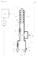
- Fig. 1 is a schematic drawing of entire construction of an engine 100 according to a first embodiment of the present invention.
- Fig. 2 is a flow chart of a control flow of the engine 100 according to the first embodiment of the present invention.
- Fig. 3 is a flow chart of another control flow.
- Fig. 4 is a schematic drawing of entire construction of an engine 200 according to a second embodiment of the present invention.
- Fig. 5 is a flow chart of a control flow of the engine 200 according to the second embodiment of the present invention.
- Fig. 6 is a flow chart of another control flow.
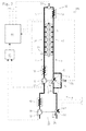
- Fig. 7 is a schematic drawing of entire construction of an engine 300 according to a third embodiment of the present invention.
- the engine 100 according to the first embodiment of the present invention is a direct injection type 6-cylindered engine and mainly includes an intake manifold 30 to which an intake path 2 is connected, an exhaust manifold 40 to which an exhaust path 3 is connected, and a common rail type fuel injection device (hereinafter, referred to as fuel injection device) 15.
- fuel injection device a common rail type fuel injection device
- the engine 100 includes a variable series supercharging system 7 having a high-pressure supercharger 10 and a low-pressure supercharger 20.
- the high-pressure supercharger 10 includes a turbine 12 rotationally driven by receiving exhaust gas flowing in the exhaust path 3 and a compressor 11 rotationally driven by the turbine 12 so as to compress intake air flowing in the intake path 2.
- the low-pressure supercharger 20 includes a turbine 22 rotationally driven by receiving exhaust gas flowing in the exhaust path 3 and a compressor 21 rotationally driven by the turbine 22 so as to compress intake air flowing in the intake path 2.
- the compressor 11 of the high-pressure supercharger 10 is arranged downstream the compressor 21 of the low-pressure supercharger 20, and the turbine 12 of the high-pressure supercharger 10 is arranged upstream the turbine 22 of the low-pressure supercharger 20.
- the high-pressure supercharger 10 is a variable capacity type supercharger and has a high-pressure supercharger variable actuator 14.
- the high-pressure supercharger variable actuator 14 controls vane opening degree by controlling a variable vane 13 provided in the high-pressure supercharger 10. Accordingly, flow rate of exhaust gas introduced into the turbine 12 can be controlled suitably, whereby supercharging efficiency is improved in wide drive range.
- the compressor 21 of the low-pressure supercharger 20 and an intercooler 32 cooling intake air compressed in the compressor 21 are arranged.
- the compressor 11 of the high-pressure supercharger 10 and an intercooler 31 cooling intake air compressed in the compressor 11 are arranged.
- bypass path 4 is provided which bypasses exhaust gas from the upstream side to the downstream side of the turbine 12 constituting the high-pressure supercharger 10, and a bypasses flow rate control valve 25 is provided in the middle portion of the bypass path 4.
- a control device 60 mainly includes a central processing unit and a storage device.
- the control device 60 is electrically connected through an amplifier 65 to a high-pressure supercharger rotation sensor 61 provided in the high-pressure supercharger 10.
- the control device 60 is electrically connected to a supercharging pressure sensor 63 provided in the intake manifold 30 and the other sensors, forms control signals based on electric signals from the sensors, and outputs the control signals to the high-pressure supercharger variable actuator 14 and the like.
- the control of the variable vane 13 of the high-pressure supercharger 10 and the control of the bypasses flow rate control valve 25 by the control device 60 are defined as supercharger control.
- the control device 60 controls the variable vane 13 of the high-pressure supercharger 10 so as to enable the high-pressure supercharger 10 to compress intake air the most efficiently in the case that the driving state of the engine 100 is at low speed rotation and low load state, that is, at low output driving state.
- the control device 60 calculates a target high-pressure supercharger rotation speed ⁇ ctrg_hp and a target supercharging pressure Bpatrg (S110).
- the target high-pressure supercharger rotation speed ⁇ ctrg_hp is the rotation speed of the compressor 11 at which intake air can be compressed the most efficiently in the high-pressure supercharger 10, and is calculated based on the target supercharging pressure Bpatrg, a map stored in the storage device of the control device 60 and the like.
- the target supercharging pressure Bpatrg is the supercharging pressure at which fuel combustion following the driving state of the engine 100 can be optimized, and is calculated based on a map stored in the storage device of the control device 60 and the like.
- the control device 60 judges as condition (11) whether the absolute value of the difference between a high-pressure supercharger rotation speed Nta_hp detected by the high-pressure supercharger rotation sensor 61 and the target high-pressure supercharger rotation speed ⁇ ctrg_hp is smaller than a predetermined value ⁇ 11, and judges as condition (12) whether a supercharging pressure Bpa detected by a supercharging pressure sensor 63 and the target supercharging pressure Bpatrg is smaller than a predetermined value ⁇ 12 (S120).
- the control device 60 judges that the high-pressure supercharger rotation speed Nta_hp is the supercharger rotation speed of the high-pressure supercharger 10 at which intake air can be compressed the most efficiently in the variable series supercharging system 7 and the supercharging pressure Bpa is the most suitable supercharging pressure to the fuel combustion.
- the control device 60 judges that the high-pressure supercharger rotation speed Nta_hp is not the supercharger rotation speed at which intake air can be compressed the most efficiently or that the supercharging pressure Bpa is not the most suitable supercharging pressure to the fuel combustion.
- control device 60 controls the variable vane 13 of the high-pressure supercharger 10 so as to control the vane opening degree until the condition (11) is satisfied (S140). Subsequently, the control device 60 controls the variable vane 13 of the high-pressure supercharger 10 so as to control the vane opening degree until the condition (12) is satisfied (S150).
- variable vane 13 of the high-pressure supercharger 10 is controlled while employing the high-pressure supercharger rotation speed Nta_hp and the supercharging pressure Bpa as feedback values, whereby the variable series supercharging system 7 can be controlled accurately.
- the control device 60 controls the variable vane 13 so that the high-pressure supercharger 10 can compress intake air the most efficiently in the case that the driving state of the engine 100 is shifting from the low output driving state to the high rotation and high load state, that is, the high output driving state.
- the control device 60 controls the bypasses flow rate control valve 25 so as to realize the optimum supercharging pressure for the fuel combustion.
- the control device 60 calculates a target high-pressure supercharger rotation speed ⁇ ctrg_hp and a target supercharging pressure Bpatrg (S210).
- the target high-pressure supercharger rotation speed ⁇ ctrg_hp is the rotation speed of the compressor 11 at which intake air can be compressed the most efficiently in the high-pressure supercharger 10, and is calculated based on the target supercharging pressure Bpatrg, a map stored in the storage device of the control device 60 and the like.
- the target supercharging pressure Bpatrg is the supercharging pressure at which fuel combustion following the driving state of the engine 100 can be optimized, and is calculated based on a map stored in the storage device of the control device 60 and the like.
- the control device 60 judges as condition (13) whether the absolute value of the difference between a high-pressure supercharger rotation speed Nta_hp detected by the high-pressure supercharger rotation sensor 61 and the target high-pressure supercharger rotation speed ⁇ ctrg_hp is smaller than a predetermined value ⁇ 13, and judges as condition (14) whether a supercharging pressure Bpa detected by a supercharging pressure sensor 63 and the target supercharging pressure Bpatrg is smaller than a predetermined value ⁇ 14 (S220).
- the control device 60 judges that the high-pressure supercharger rotation speed Nta_hp is the supercharger rotation speed of the high-pressure supercharger 10 at which intake air can be compressed the most efficiently in the variable series supercharging system 7 and the supercharging pressure Bpa is the most suitable supercharging pressure to the fuel combustion.
- the control device 60 judges that the high-pressure supercharger rotation speed Nta_hp is not the supercharger rotation speed of the high-pressure supercharger 10 at which intake air can be compressed the most efficiently or that the supercharging pressure Bpa is not the most suitable supercharging pressure to the fuel combustion.
- control device 60 controls the bypasses flow rate control valve 25 so as to control the vane opening degree until the condition (13) is satisfied (S240). Subsequently, the control device 60 controls the bypasses flow rate control valve 25 so as to control the vane opening degree until the condition (14) is satisfied (S250).
- variable vane 13 of the high-pressure supercharger 10 and the bypasses flow rate control valve 25 are controlled while employing the high-pressure supercharger rotation speed Nta_hp and the supercharging pressure Bpa as feedback values, whereby the variable series supercharging system 7 can be controlled accurately.
- the high-pressure supercharger rotation speed Nta_hp directly concerned with the action of the high-pressure supercharger 10 is employed as the feedback value, whereby time lag in the supercharger control can be reduced. Accordingly, occurrence of overshoot in which the supercharging pressure Bpa is more than the target supercharging pressure Bpatrg and undershoot in which the supercharging pressure Bpa is less than the target supercharging pressure Bpatrg can be reduced.
- the high-pressure supercharger rotation speed Nta_hp is employed as the feedback value, whereby accurate control can be performed without considering dispersion of products of the high-pressure supercharger 10.
- the overspeed can be prevented by increasing the opening degree of the bypasses flow rate control valve 25. Accordingly, the rotation speed of the high-pressure supercharger 10 is prevented from being larger than the maximum permissible rotation speed so as to improve the safety, and a waste gate or the like as a safety device is made unnecessary.
- the engine 200 according to the second embodiment of the present invention is a direct injection type 6-cylindered engine and mainly includes the intake manifold 30 to which the intake path 2 is connected, the exhaust manifold 40 to which the exhaust path 3 is connected, and the common rail type fuel injection device (hereinafter, referred to as fuel injection device) 15.
- fuel injection device common rail type fuel injection device
- the engine 200 includes a variable series supercharging system 8 having the high-pressure supercharger 10 and the low-pressure supercharger 20.
- the high-pressure supercharger 10 includes the turbine 12 rotationally driven by receiving exhaust gas flowing in the exhaust path 3 and the compressor 11 rotationally driven by the turbine 12 so as to compress intake air flowing in the intake path 2.
- the low-pressure supercharger 20 includes the turbine 22 rotationally driven by receiving exhaust gas flowing in the exhaust path 3 and a compressor 21 rotationally driven by the turbine 22 so as to compress intake air flowing in the intake path 2.
- the compressor 11 of the high-pressure supercharger 10 is arranged downstream the compressor 21 of the low-pressure supercharger 20, and the turbine 12 of the high-pressure supercharger 10 is arranged upstream the turbine 22 of the low-pressure supercharger 20.
- the low-pressure supercharger 20 is a variable capacity type supercharger and has a low-pressure supercharger variable actuator 24.
- the low-pressure supercharger variable actuator 24 controls vane opening degree by controlling a variable vane 23 provided in the low-pressure supercharger 20. Accordingly, flow rate of exhaust gas introduced into the turbine 22 can be controlled suitably, whereby supercharging efficiency is improved in wide drive range.
- the compressor 21 of the low-pressure supercharger 20 and the intercooler 32 cooling intake air compressed in the compressor 21 are arranged.
- the compressor 11 of the high-pressure supercharger 10 and the intercooler 31 cooling intake air compressed in the compressor 11 are arranged.
- the turbine 12 of the high-pressure supercharger 10 is arranged, and at the downstream side thereof, the turbine 22 of the low-pressure supercharger 20 is arranged.
- the bypass path 4 is provided which bypasses exhaust gas from the upstream side to the downstream side of the turbine 12 constituting the high-pressure supercharger 10, and a bypasses flow rate control valve 25 is provided in the middle portion of the bypass path 4.
- a control device 60 mainly includes a central processing unit and a storage device.
- the control device 60 is electrically connected through the amplifier 65 to a low-pressure supercharger rotation sensor 62 provided in the low-pressure supercharger 20.
- the control device 60 is electrically connected to the supercharging pressure sensor 63 provided in the intake manifold 30 and the other sensors, forms control signals based on electric signals from the sensors, and outputs the control signals to the low-pressure supercharger variable actuator 24 and the like.
- the control of the variable vane 23 of the low-pressure supercharger 20 and the control of the bypasses flow rate control valve 25 by the control device 60 are defined as supercharger control.
- the control device 60 controls the variable vane 23 of the low-pressure supercharger 20 so as to enable the low-pressure supercharger 20 to compress intake air the most efficiently in the case that the driving state of the engine 200 is at low speed rotation and low load state, that is, at low output driving state.
- the control device 60 calculates a target low-pressure supercharger rotation speed ⁇ ctrg_lp and a target supercharging pressure Bpatrg (S310).
- the target low-pressure supercharger rotation speed ⁇ ctrg_lp is the rotation speed of the compressor 21 at which intake air can be compressed the most efficiently in the low-pressure supercharger 20, and is calculated based on the target supercharging pressure Bpatrg, a map stored in the storage device of the control device 60 and the like.
- the target supercharging pressure Bpatrg is the supercharging pressure at which fuel combustion following the driving state of the engine 200 can be optimized, and is calculated based on a map stored in the storage device of the control device 60 and the like.
- the control device 60 judges as condition (21) whether the absolute value of the difference between a low-pressure supercharger rotation speed Nta_lp detected by the high-pressure supercharger rotation sensor 61 and the target low-pressure supercharger rotation speed ⁇ ctrg_lp is smaller than a predetermined value ⁇ 21, and judges as condition (22) whether a supercharging pressure Bpa detected by the supercharging pressure sensor 63 and the target supercharging pressure Bpatrg is smaller than a predetermined value ⁇ 22 (S320).
- the control device 60 judges that the low-pressure supercharger rotation speed Nta_lp is the supercharger rotation speed of the low-pressure supercharger 20 at which intake air can be compressed the most efficiently in the variable series supercharging system 8 and the supercharging pressure Bpa is the most suitable supercharging pressure to the fuel combustion.
- the control device 60 judges that the low-pressure supercharger rotation speed Nta_lp is not the supercharger rotation speed of the low-pressure supercharger 20 at which intake air can be compressed the most efficiently or that the supercharging pressure Bpa is not the most suitable supercharging pressure to the fuel combustion.
- control device 60 controls the variable vane 23 of the low-pressure supercharger 20 so as to control the vane opening degree until the condition (21) is satisfied (S340). Subsequently, the control device 60 controls the variable vane 23 of the low-pressure supercharger 20 so as to control the vane opening degree until the condition (22) is satisfied (S350).
- variable vane 23 of the low-pressure supercharger 20 is controlled while employing the low-pressure supercharger rotation speed Nta_lp and the supercharging pressure Bpa as feedback values, whereby the variable series supercharging system 8 can be controlled accurately.
- the control device 60 controls the variable vane 23 so that the low-pressure supercharger 20 can compress intake air the most efficiently in the case that the driving state of the engine 200 is shifting from the low output driving state to the high rotation and high load state, that is, the high output driving state.
- the control device 60 controls the bypasses flow rate control valve 25 so as to realize the optimum supercharging pressure for the fuel combustion.
- the control device 60 calculates a target low-pressure supercharger rotation speed ⁇ ctrg_lp and a target supercharging pressure Bpatrg (S410).
- the target low-pressure supercharger rotation speed ⁇ ctrg_lp is the rotation speed of the compressor 21 at which intake air can be compressed the most efficiently in the low-pressure supercharger 20, and is calculated based on the target supercharging pressure Bpatrg, a map stored in the storage device of the control device 60 and the like.
- the target supercharging pressure Bpatrg is the supercharging pressure at which fuel combustion following the driving state of the engine 100 can be optimized, and is calculated based on a map stored in the storage device of the control device 60 and the like.
- the control device 60 judges as condition (23) whether the absolute value of the difference between a low-pressure supercharger rotation speed Nta_lp detected by the low-pressure supercharger rotation sensor 62 and the target low-pressure supercharger rotation speed ⁇ ctrg_lp is smaller than a predetermined value ⁇ 23, and judges as condition (24) whether a supercharging pressure Bpa detected by a supercharging pressure sensor 63 and the target supercharging pressure Bpatrg is smaller than a predetermined value ⁇ 24 (S420).
- the control device 60 judges that the high-pressure supercharger rotation speed Nta_lp is the supercharger rotation speed of the low-pressure supercharger 10 at which intake air can be compressed the most efficiently in the variable series supercharging system 7 and the supercharging pressure Bpa is the most suitable supercharging pressure to the fuel combustion.
- the control device 60 judges that the low-pressure supercharger rotation speed Nta_lp is not the supercharger rotation speed of the low-pressure supercharger 20 at which intake air can be compressed the most efficiently or that the supercharging pressure Bpa is not the most suitable supercharging pressure to the fuel combustion.
- control device 60 controls the bypasses flow rate control valve 25 so as to control the vane opening degree until the condition (23) is satisfied (S440). Subsequently, the control device 60 controls the bypasses flow rate control valve 25 so as to control the vane opening degree until the condition (24) is satisfied (S450).
- variable vane 23 of the low-pressure supercharger 20 and the bypasses flow rate control valve 25 are controlled while employing the high-pressure supercharger rotation speed Nta_lp and the supercharging pressure Bpa as feedback values, whereby the variable series supercharging system 8 can be controlled accurately.
- the low-pressure supercharger rotation speed Nta_lp directly concerned with the action of the low-pressure supercharger 20 is employed as the feedback value, whereby time lag in the supercharger control can be reduced. Accordingly, occurrence of overshoot in which the supercharging pressure Bpa is more than the target supercharging pressure Bpatrg and undershoot in which the supercharging pressure Bpa is less than the target supercharging pressure Bpatrg can be reduced.
- the low-pressure supercharger rotation speed Nta_lp is employed as the feedback value, whereby accurate control can be performed without considering dispersion of products of the low-pressure supercharger 20.
- the overspeed can be prevented by increasing the opening degree of the bypasses flow rate control valve 25. Accordingly, the rotation speed of the low-pressure supercharger 20 is prevented from being larger than the maximum permissible rotation speed so as to improve the safety, and a waste gate or the like as a safety device is made unnecessary.
- the engine 300 according to the third embodiment of the present invention is a direct injection type 6-cylindered engine and mainly includes the intake manifold 30 to which an intake path 2 is connected, the exhaust manifold 40 to which an exhaust path 3 is connected, and the common rail type fuel injection device (hereinafter, referred to as fuel injection device) 15.
- fuel injection device common rail type fuel injection device
- the engine 300 includes a variable series supercharging system 9 having the high-pressure supercharger 10 and the low-pressure supercharger 20.
- the high-pressure supercharger 10 includes the turbine 12 rotationally driven by receiving exhaust gas flowing in the exhaust path 3 and the compressor 11 rotationally driven by the turbine 12 so as to compress intake air flowing in the intake path 2.
- the low-pressure supercharger 20 includes the turbine 22 rotationally driven by receiving exhaust gas flowing in the exhaust path 3 and the compressor 21 rotationally driven by the turbine 22 so as to compress intake air flowing in the intake path 2.
- the compressor 11 of the high-pressure supercharger 10 is arranged downstream the compressor 21 of the low-pressure supercharger 20, and the turbine 12 of the high-pressure supercharger 10 is arranged upstream the turbine 22 of the low-pressure supercharger 20.
- Each of the high-pressure supercharger 10 and the low-pressure supercharger 20 is a variable capacity type supercharger.
- the high-pressure supercharger 10 has the high-pressure supercharger variable actuator 14, and the low-pressure supercharger 20 has the low-pressure supercharger variable actuator 24.
- the high-pressure supercharger variable actuator 14 controls vane opening degree by controlling the variable vane 13 provided in the turbine 12 of the high-pressure supercharger 10.
- the low-pressure supercharger variable actuator 24 controls vane opening degree by controlling the variable vane 23 provided in the turbine 22 of the low-pressure supercharger 20.
- the high-pressure supercharger 10 and the low-pressure supercharger 20 controls the vane opening degree by the variable actuators 14 and 24 so as to control flow rate of exhaust gas introduced into the turbines 12 and 22, whereby supercharging efficiency is improved in wide drive range.
- the compressor 21 of the low-pressure supercharger 20 and the intercooler 32 cooling intake air compressed in the compressor 21 are arranged.
- the compressor 11 of the high-pressure supercharger 10 and the intercooler 31 cooling intake air compressed in the compressor 11 are arranged.
- the turbine 12 of the high-pressure supercharger 10 is arranged, and at the downstream side thereof, the turbine 22 of the low-pressure supercharger 20 is arranged.
- the bypass path 4 is provided which bypasses exhaust gas from the upstream side to the downstream side of the turbine 12 constituting the high-pressure supercharger 10, and a bypasses flow rate control valve 25 is provided in the middle portion of the bypass path 4.
- An EGR device 50 mixes a part of exhaust gas as recirculating gas with intake air.
- the EGR device 50 includes an EGR path 5 guiding a part of exhaust gas flowing in the exhaust manifold 40 to the intake manifold 30, an EGR cooler 53 cooling exhaust gas flowing in the EGR path 5, and an EGR valve 51 controlling flow rate of recirculating gas flowing in the EGR path 5, that is, the exhaust gas.
- a control device 60 mainly includes a central processing unit and a storage device.
- the control device 60 is electrically connected through the amplifier 65 to the high-pressure supercharger rotation sensor 61 provided in the high-pressure supercharger 10 and the low-pressure supercharger rotation sensor 62 provided in the low-pressure supercharger 20.
- the control device 60 is electrically connected to the supercharging pressure sensor 63 provided in the intake manifold 30 and the other sensors, forms control signals based on electric signals from the sensors, and outputs the control signals to the EGR valve 51 and the like.
- EGR control the control of the EGR valve 51 by the control device 60 is defined as EGR control.
- the control device 60 has function for calculating flow rate of recirculating gas flowing in the EGR path 5. Accordingly, recirculating gas of optimum amount corresponding to the driving state of the engine 300 can be mixed with intake air.
- a map showing the relation between the rotational speed of each of the superchargers 10 and 20 and the exhaust gas pressure in the exhaust manifold 40 is previously stored in the control device 60, and firstly, the exhaust gas pressure in the exhaust manifold 40 corresponding to the rotational speed of each of the superchargers 10 and 20 is called. Subsequently, by comparing supercharging pressure detected by the supercharging pressure sensor 63 with the called exhaust gas pressure, the pressure difference is grasped, and flow rate of recirculating gas flowing in the EGR path 5 is calculated from the pressure difference.
- the flow rate of recirculating gas can be calculated accurately by employing the rotational speed of each of the superchargers 10 and 20.
- the calculated flow rate of recirculating gas is employed as a feedback value, whereby the EGR valve 51 can be controlled accurately.
- control device 60 has function for calculating flow rate of exhaust gas flowing in the bypass path 4. Accordingly, the bypasses flow rate control valve 25 can be controlled so as to enable the variable series supercharging system 9 to compress intake air the most efficiently.
- a map showing the relation between the difference of rotational speed of each of the superchargers 10 and 20 and the flow rate of the exhaust gas flowing in the bypass path 4, and the flow rate of the exhaust gas flowing in the bypass path 4 corresponding to the difference of rotational speed of each of the superchargers 10 and 20 is called.
- the flow rate of the exhaust gas flowing in the bypass path 4 can be calculated accurately by employing the rotational speed of each of the superchargers 10 and 20.
- the calculated flow rate of exhaust gas flowing in the bypass path 4 is employed as a feedback value, whereby the bypasses flow rate control valve 25 can be controlled accurately.
- the present invention can be employed for an engine having a variable series supercharging system.
Landscapes
- Engineering & Computer Science (AREA)
- Chemical & Material Sciences (AREA)
- Combustion & Propulsion (AREA)
- Mechanical Engineering (AREA)
- General Engineering & Computer Science (AREA)
- Physics & Mathematics (AREA)
- Thermal Sciences (AREA)
- Fluid Mechanics (AREA)
- Analytical Chemistry (AREA)
- Supercharger (AREA)
- Output Control And Ontrol Of Special Type Engine (AREA)
Abstract
Description
- The present invention relates to an art of control of an engine having a variable series supercharging system.
- Conventionally, an engine having a series supercharging system is known as an engine having a plurality of superchargers. In the series supercharging system, turbines of the superchargers rotated by receiving exhaust gas are arranged in series in one exhaust path, and compressors of the superchargers compressing intake air are arranged in series in one intake path.
- A variable capacity type supercharger is also known in which exhaust gas is controlled suitably its flow rate and then introduced into a turbine constituting the supercharger so as to improve supercharging efficiency. A series supercharging system in which two superchargers compress intake air flowing in one exhaust path and at least one of the superchargers is variable capacity type is defined as a variable series supercharging system. The Patent Literature 1 discloses an engine having a variable series supercharging system.
- Conventionally, in control of capacity in a variable capacity type supercharger, feedback control is performed with supercharging pressure detected by a supercharging pressure sensor. However, the supercharging pressure is indirect physical quantity about the action of the supercharger and is disadvantageous because the control of capacity of the supercharger cannot be performed accurately. Especially, the variable series supercharging system having the variable capacity type superchargers is disadvantageous because the control of capacity cannot be performed accurately further.
- Patent Literature 1: the Japanese Patent Laid Open Gazette
2006-29110 - Then, the purpose of the present invention is to provide an engine and a control method which can control accurately a variable series supercharging system.
- Explanation will be given on means of the present invention for solving the problems.
- According to the first aspect of the present invention, an engine in which intake air guided by one intake path is distributed to cylinders, and exhaust gas collected from the cylinders is discharged through one exhaust path includes a variable series supercharging system having a high-pressure supercharger and a low-pressure supercharger each of which is constituted by a turbine rotated by receiving the exhaust gas flowing in the exhaust path and a compressor driven by the turbine so as to compress the intake air flowing in the intake path, a supercharging pressure sensor detecting pressure of the intake air compressed by the variable series supercharging system, a high-pressure supercharger rotation sensor detecting high-pressure supercharger rotation speed of the high-pressure supercharger, a high-pressure supercharger variable actuator controlling capacity of the high-pressure supercharger, and a control device enabling the high-pressure supercharger variable actuator to be controlled. The control device controls the high-pressure supercharger variable actuator based on detection signals from the supercharging pressure sensor and the high-pressure supercharger rotation sensor.
- According to the second aspect of the present invention, the engine according to the first aspect further includes a bypass path bypassing exhaust gas from an upstream side of a turbine constituting the high-pressure supercharger to a downstream side of the turbine, a bypasses flow rate control valve controlling flow rate of the exhaust gas flowing in the bypass path, and a control device enabling the high-pressure supercharger variable actuator and the bypasses flow rate control valve to be controlled. The control device controls the high-pressure supercharger variable actuator and the bypasses flow rate control valve based on detection signals from the supercharging pressure sensor and the high-pressure supercharger rotation sensor.
- According to the third aspect of the present invention, the engine according to the first aspect further includes a low-pressure supercharger rotation sensor detecting low-pressure supercharger rotation speed of the low-pressure supercharger, a low-pressure supercharger variable actuator controlling capacity of the low-pressure supercharger, and a control device enabling the low-pressure supercharger variable actuator to be controlled. The control device controls the low-pressure supercharger variable actuator based on detection signals from the supercharging pressure sensor and the low-pressure supercharger rotation sensor.
- According to the fourth aspect of the present invention, the engine according to the third aspect further includes a bypass path bypassing exhaust gas from an upstream side of a turbine constituting the high-pressure supercharger to a downstream side of the turbine, a bypasses flow rate control valve controlling flow rate of the exhaust gas flowing in the bypass path, and a control device enabling the low-pressure supercharger variable actuator and the bypasses flow rate control valve to be controlled. The control device controls the low-pressure supercharger variable actuator and the bypasses flow rate control valve based on detection signals from the supercharging pressure sensor and the low-pressure supercharger rotation sensor.
- According to the fifth aspect of the present invention, the engine according to the third aspect further includes a bypass path bypassing exhaust gas from an upstream side of a turbine constituting the high-pressure supercharger to a downstream side of the turbine, a bypasses flow rate control valve controlling flow rate of the exhaust gas flowing in the bypass path, an EGR path guiding a part of the exhaust gas flowing in the exhaust path to the intake path, an EGR valve controlling flow rate of the exhaust gas flowing in the EGR path, and a control device enabling the EGR valve to be controlled. The control device calculates the flow rate of the exhaust gas flowing in the EGR path based on detection signals from the supercharging pressure sensor, the high-pressure supercharger rotation sensor and the low-pressure supercharger rotation sensor, and controls the EGR valve according to a result of the calculation.
- The present invention constructed as the above brings the following effects.
- According to the first aspect of the present invention, the capacity of the supercharger is controlled while employing the supercharging pressure and the high-pressure supercharger rotation speed as feedback values, whereby the variable series supercharging system can be controlled accurately.
- According to the second aspect of the present invention, the capacity of the supercharger and the opening degree of the bypasses flow rate control valve are controlled while employing the supercharging pressure and the high-pressure supercharger rotation speed as feedback values, whereby the variable series supercharging system can be controlled accurately further.
- According to the third aspect of the present invention, the capacity of the supercharger is controlled while employing the supercharging pressure and the low-pressure supercharger rotation speed as feedback values, whereby the variable series supercharging system can be controlled accurately.
- According to the fourth aspect of the present invention, the capacity of the supercharger and the opening degree of the bypasses flow rate control valve are controlled while employing the supercharging pressure and the low-pressure supercharger rotation speed as feedback values, whereby the variable series supercharging system can be controlled accurately further.
- According to the fifth aspect of the present invention, the capacity of the supercharger and the opening degree of the bypasses flow rate control valve are controlled while employing the supercharging pressure, the high-pressure supercharger rotation speed and the low-pressure supercharger rotation speed as feedback values, whereby the variable series supercharging system can be controlled accurately. The flow rate of exhaust gas flowing in the EGR path can be calculated, whereby the EGR valve can be controlled accurately.
-
- [
Fig. 1 ] It is a schematic drawing of entire construction of an engine according to a first embodiment of the present invention. - [
Fig. 2 ] It is a flow chart of a control flow of the engine according to the first embodiment of the present invention. - [
Fig. 3 ] It is a flow chart of another control flow of the engine according to the first embodiment of the present invention. - [
Fig. 4 ] It is a schematic drawing of entire construction of an engine according to a second embodiment of the present invention. - [
Fig. 5 ] It is a flow chart of a control flow of the engine according to the second embodiment of the present invention. - [
Fig. 6 ] It is a flow chart of another control flow of the engine according to the second embodiment of the present invention. - [
Fig. 7 ] It is a schematic drawing of entire construction of an engine according to a third embodiment of the present invention. -
- 2
- intake path
- 3
- exhaust path
- 4
- bypass path
- 5
- EGR path
- 7
- variable series supercharging system
- 8
- variable series supercharging system
- 9
- variable series supercharging system
- 10
- high-pressure supercharger
- 11
- compressor
- 12
- turbine
- 13
- variable vane
- 14
- high-pressure supercharger variable actuator
- 20
- low-pressure supercharger
- 21
- compressor
- 22
- turbine
- 23
- variable vane
- 24
- low-pressure supercharger variable actuator
- 25
- bypasses flow rate control valve
- 30
- intake manifold
- 40
- exhaust manifold
- 50
- EGR device
- 51
- EGR valve
- 60
- control device
- 61
- high-pressure supercharger rotation sensor
- 62
- low-pressure supercharger rotation sensor
- 63
- supercharging pressure sensor
- 100
- engine
- 200
- engine
- 300
- engine
- Bpa
- supercharging pressure
- Bpatrg
- target supercharging pressure
- Nta_hp
- high-pressure supercharger rotation speed
- ωctrg_hp
- target high-pressure supercharger rotation speed
- Nta_lp
- low-pressure supercharger rotation speed
- ωctrg_lp
- target low-pressure supercharger rotation speed
- Next, explanation will be given on the embodiments of the present invention.
-
Fig. 1 is a schematic drawing of entire construction of an engine 100 according to a first embodiment of the present invention.Fig. 2 is a flow chart of a control flow of the engine 100 according to the first embodiment of the present invention.Fig. 3 is a flow chart of another control flow.Fig. 4 is a schematic drawing of entire construction of anengine 200 according to a second embodiment of the present invention.Fig. 5 is a flow chart of a control flow of theengine 200 according to the second embodiment of the present invention.Fig. 6 is a flow chart of another control flow.Fig. 7 is a schematic drawing of entire construction of anengine 300 according to a third embodiment of the present invention. - Firstly, explanation will be given on the engine 100 according to the first embodiment of the present invention. The engine 100 according to the first embodiment of the present invention is a direct injection type 6-cylindered engine and mainly includes an
intake manifold 30 to which anintake path 2 is connected, an exhaust manifold 40 to which anexhaust path 3 is connected, and a common rail type fuel injection device (hereinafter, referred to as fuel injection device) 15. - The engine 100 includes a variable series supercharging system 7 having a high-
pressure supercharger 10 and a low-pressure supercharger 20. The high-pressure supercharger 10 includes aturbine 12 rotationally driven by receiving exhaust gas flowing in theexhaust path 3 and acompressor 11 rotationally driven by theturbine 12 so as to compress intake air flowing in theintake path 2. The low-pressure supercharger 20 includes aturbine 22 rotationally driven by receiving exhaust gas flowing in theexhaust path 3 and acompressor 21 rotationally driven by theturbine 22 so as to compress intake air flowing in theintake path 2. Thecompressor 11 of the high-pressure supercharger 10 is arranged downstream thecompressor 21 of the low-pressure supercharger 20, and theturbine 12 of the high-pressure supercharger 10 is arranged upstream theturbine 22 of the low-pressure supercharger 20. - The high-
pressure supercharger 10 is a variable capacity type supercharger and has a high-pressuresupercharger variable actuator 14. The high-pressuresupercharger variable actuator 14 controls vane opening degree by controlling avariable vane 13 provided in the high-pressure supercharger 10. Accordingly, flow rate of exhaust gas introduced into theturbine 12 can be controlled suitably, whereby supercharging efficiency is improved in wide drive range. - In the
intake path 2, from the upstream side toward theintake manifold 30, thecompressor 21 of the low-pressure supercharger 20 and anintercooler 32 cooling intake air compressed in thecompressor 21 are arranged. At the downstream side of these members, thecompressor 11 of the high-pressure supercharger 10 and anintercooler 31 cooling intake air compressed in thecompressor 11 are arranged. - In the
exhaust path 3, from the exhaust manifold 40 toward the downstream side, theturbine 12 of the high-pressure supercharger 10 is arranged, and at the downstream side thereof, theturbine 22 of the low-pressure supercharger 20 is arranged. A bypass path 4 is provided which bypasses exhaust gas from the upstream side to the downstream side of theturbine 12 constituting the high-pressure supercharger 10, and a bypasses flowrate control valve 25 is provided in the middle portion of the bypass path 4. - A control device 60 mainly includes a central processing unit and a storage device. The control device 60 is electrically connected through an amplifier 65 to a high-pressure
supercharger rotation sensor 61 provided in the high-pressure supercharger 10. The control device 60 is electrically connected to a superchargingpressure sensor 63 provided in theintake manifold 30 and the other sensors, forms control signals based on electric signals from the sensors, and outputs the control signals to the high-pressuresupercharger variable actuator 14 and the like. Hereinafter, the control of thevariable vane 13 of the high-pressure supercharger 10 and the control of the bypasses flowrate control valve 25 by the control device 60 are defined as supercharger control. - Explanation will be given on the supercharger control of the engine 100 according to the first embodiment of the present invention referring to
Fig. 2 . The control device 60 controls thevariable vane 13 of the high-pressure supercharger 10 so as to enable the high-pressure supercharger 10 to compress intake air the most efficiently in the case that the driving state of the engine 100 is at low speed rotation and low load state, that is, at low output driving state. - Firstly, the control device 60 calculates a target high-pressure supercharger rotation speed ωctrg_hp and a target supercharging pressure Bpatrg (S110).
The target high-pressure supercharger rotation speed ωctrg_hp is the rotation speed of thecompressor 11 at which intake air can be compressed the most efficiently in the high-pressure supercharger 10, and is calculated based on the target supercharging pressure Bpatrg, a map stored in the storage device of the control device 60 and the like.
The target supercharging pressure Bpatrg is the supercharging pressure at which fuel combustion following the driving state of the engine 100 can be optimized, and is calculated based on a map stored in the storage device of the control device 60 and the like. - The control device 60 judges as condition (11) whether the absolute value of the difference between a high-pressure supercharger rotation speed Nta_hp detected by the high-pressure
supercharger rotation sensor 61 and the target high-pressure supercharger rotation speed ωctrg_hp is smaller than a predetermined value α11, and judges as condition (12) whether a supercharging pressure Bpa detected by a superchargingpressure sensor 63 and the target supercharging pressure Bpatrg is smaller than a predetermined value α12 (S120). - In the case that the conditions (11) and (12) are satisfied at S120, the control device 60 judges that the high-pressure supercharger rotation speed Nta_hp is the supercharger rotation speed of the high-
pressure supercharger 10 at which intake air can be compressed the most efficiently in the variable series supercharging system 7 and the supercharging pressure Bpa is the most suitable supercharging pressure to the fuel combustion. - On the other hand, in the case that the condition (11) or (12) is not satisfied at S120, the control device 60 judges that the high-pressure supercharger rotation speed Nta_hp is not the supercharger rotation speed at which intake air can be compressed the most efficiently or that the supercharging pressure Bpa is not the most suitable supercharging pressure to the fuel combustion.
- Then, the control device 60 controls the
variable vane 13 of the high-pressure supercharger 10 so as to control the vane opening degree until the condition (11) is satisfied (S140). Subsequently, the control device 60 controls thevariable vane 13 of the high-pressure supercharger 10 so as to control the vane opening degree until the condition (12) is satisfied (S150). - As mentioned above, the
variable vane 13 of the high-pressure supercharger 10 is controlled while employing the high-pressure supercharger rotation speed Nta_hp and the supercharging pressure Bpa as feedback values, whereby the variable series supercharging system 7 can be controlled accurately. - Next, explanation will be given on another supercharger control of the engine 100 according to the first embodiment of the present invention referring to
Fig. 3 . - The control device 60 controls the
variable vane 13 so that the high-pressure supercharger 10 can compress intake air the most efficiently in the case that the driving state of the engine 100 is shifting from the low output driving state to the high rotation and high load state, that is, the high output driving state. The control device 60 controls the bypasses flowrate control valve 25 so as to realize the optimum supercharging pressure for the fuel combustion. - The control device 60 calculates a target high-pressure supercharger rotation speed ωctrg_hp and a target supercharging pressure Bpatrg (S210).
The target high-pressure supercharger rotation speed ωctrg_hp is the rotation speed of thecompressor 11 at which intake air can be compressed the most efficiently in the high-pressure supercharger 10, and is calculated based on the target supercharging pressure Bpatrg, a map stored in the storage device of the control device 60 and the like.
The target supercharging pressure Bpatrg is the supercharging pressure at which fuel combustion following the driving state of the engine 100 can be optimized, and is calculated based on a map stored in the storage device of the control device 60 and the like. - The control device 60 judges as condition (13) whether the absolute value of the difference between a high-pressure supercharger rotation speed Nta_hp detected by the high-pressure
supercharger rotation sensor 61 and the target high-pressure supercharger rotation speed ωctrg_hp is smaller than a predetermined value α13, and judges as condition (14) whether a supercharging pressure Bpa detected by a superchargingpressure sensor 63 and the target supercharging pressure Bpatrg is smaller than a predetermined value α14 (S220). - In the case that the conditions (13) and (14) are satisfied at S220, the control device 60 judges that the high-pressure supercharger rotation speed Nta_hp is the supercharger rotation speed of the high-
pressure supercharger 10 at which intake air can be compressed the most efficiently in the variable series supercharging system 7 and the supercharging pressure Bpa is the most suitable supercharging pressure to the fuel combustion. - On the other hand, in the case that the condition (13) or (14) is not satisfied at S220, the control device 60 judges that the high-pressure supercharger rotation speed Nta_hp is not the supercharger rotation speed of the high-
pressure supercharger 10 at which intake air can be compressed the most efficiently or that the supercharging pressure Bpa is not the most suitable supercharging pressure to the fuel combustion. - Then, the control device 60 controls the bypasses flow
rate control valve 25 so as to control the vane opening degree until the condition (13) is satisfied (S240). Subsequently, the control device 60 controls the bypasses flowrate control valve 25 so as to control the vane opening degree until the condition (14) is satisfied (S250). - As mentioned above, the
variable vane 13 of the high-pressure supercharger 10 and the bypasses flowrate control valve 25 are controlled while employing the high-pressure supercharger rotation speed Nta_hp and the supercharging pressure Bpa as feedback values, whereby the variable series supercharging system 7 can be controlled accurately. - The high-pressure supercharger rotation speed Nta_hp directly concerned with the action of the high-
pressure supercharger 10 is employed as the feedback value, whereby time lag in the supercharger control can be reduced. Accordingly, occurrence of overshoot in which the supercharging pressure Bpa is more than the target supercharging pressure Bpatrg and undershoot in which the supercharging pressure Bpa is less than the target supercharging pressure Bpatrg can be reduced. The high-pressure supercharger rotation speed Nta_hp is employed as the feedback value, whereby accurate control can be performed without considering dispersion of products of the high-pressure supercharger 10. - Furthermore, in the case that the high-pressure supercharger rotation speed Nta_hp of the high-
pressure supercharger 10 is larger than the predetermined value, the overspeed can be prevented by increasing the opening degree of the bypasses flowrate control valve 25. Accordingly, the rotation speed of the high-pressure supercharger 10 is prevented from being larger than the maximum permissible rotation speed so as to improve the safety, and a waste gate or the like as a safety device is made unnecessary. - Explanation will be given on another supercharger control of the
engine 200 according to the second embodiment of the present invention referring toFig. 4 . Theengine 200 according to the second embodiment of the present invention is a direct injection type 6-cylindered engine and mainly includes theintake manifold 30 to which theintake path 2 is connected, the exhaust manifold 40 to which theexhaust path 3 is connected, and the common rail type fuel injection device (hereinafter, referred to as fuel injection device) 15. - The
engine 200 includes a variableseries supercharging system 8 having the high-pressure supercharger 10 and the low-pressure supercharger 20. The high-pressure supercharger 10 includes theturbine 12 rotationally driven by receiving exhaust gas flowing in theexhaust path 3 and thecompressor 11 rotationally driven by theturbine 12 so as to compress intake air flowing in theintake path 2. The low-pressure supercharger 20 includes theturbine 22 rotationally driven by receiving exhaust gas flowing in theexhaust path 3 and acompressor 21 rotationally driven by theturbine 22 so as to compress intake air flowing in theintake path 2. Thecompressor 11 of the high-pressure supercharger 10 is arranged downstream thecompressor 21 of the low-pressure supercharger 20, and theturbine 12 of the high-pressure supercharger 10 is arranged upstream theturbine 22 of the low-pressure supercharger 20. - The low-
pressure supercharger 20 is a variable capacity type supercharger and has a low-pressuresupercharger variable actuator 24. The low-pressuresupercharger variable actuator 24 controls vane opening degree by controlling avariable vane 23 provided in the low-pressure supercharger 20. Accordingly, flow rate of exhaust gas introduced into theturbine 22 can be controlled suitably, whereby supercharging efficiency is improved in wide drive range. - In the
intake path 2, from the upstream side toward theintake manifold 30, thecompressor 21 of the low-pressure supercharger 20 and theintercooler 32 cooling intake air compressed in thecompressor 21 are arranged. At the downstream side of these members, thecompressor 11 of the high-pressure supercharger 10 and theintercooler 31 cooling intake air compressed in thecompressor 11 are arranged. - In the
exhaust path 3, from the exhaust manifold 40 toward the downstream side, theturbine 12 of the high-pressure supercharger 10 is arranged, and at the downstream side thereof, theturbine 22 of the low-pressure supercharger 20 is arranged. The bypass path 4 is provided which bypasses exhaust gas from the upstream side to the downstream side of theturbine 12 constituting the high-pressure supercharger 10, and a bypasses flowrate control valve 25 is provided in the middle portion of the bypass path 4. - A control device 60 mainly includes a central processing unit and a storage device. The control device 60 is electrically connected through the amplifier 65 to a low-pressure supercharger rotation sensor 62 provided in the low-
pressure supercharger 20. The control device 60 is electrically connected to the superchargingpressure sensor 63 provided in theintake manifold 30 and the other sensors, forms control signals based on electric signals from the sensors, and outputs the control signals to the low-pressuresupercharger variable actuator 24 and the like. Hereinafter, the control of thevariable vane 23 of the low-pressure supercharger 20 and the control of the bypasses flowrate control valve 25 by the control device 60 are defined as supercharger control. - Explanation will be given on the supercharger control of the
engine 200 according to the first embodiment of the present invention referring toFig. 2 . The control device 60 controls thevariable vane 23 of the low-pressure supercharger 20 so as to enable the low-pressure supercharger 20 to compress intake air the most efficiently in the case that the driving state of theengine 200 is at low speed rotation and low load state, that is, at low output driving state. - Firstly, the control device 60 calculates a target low-pressure supercharger rotation speed ωctrg_lp and a target supercharging pressure Bpatrg (S310).
The target low-pressure supercharger rotation speed ωctrg_lp is the rotation speed of thecompressor 21 at which intake air can be compressed the most efficiently in the low-pressure supercharger 20, and is calculated based on the target supercharging pressure Bpatrg, a map stored in the storage device of the control device 60 and the like.
The target supercharging pressure Bpatrg is the supercharging pressure at which fuel combustion following the driving state of theengine 200 can be optimized, and is calculated based on a map stored in the storage device of the control device 60 and the like. - The control device 60 judges as condition (21) whether the absolute value of the difference between a low-pressure supercharger rotation speed Nta_lp detected by the high-pressure
supercharger rotation sensor 61 and the target low-pressure supercharger rotation speed ωctrg_lp is smaller than a predetermined value α21, and judges as condition (22) whether a supercharging pressure Bpa detected by the superchargingpressure sensor 63 and the target supercharging pressure Bpatrg is smaller than a predetermined value α22 (S320). - In the case that the conditions (21) and (22) are satisfied at S320, the control device 60 judges that the low-pressure supercharger rotation speed Nta_lp is the supercharger rotation speed of the low-
pressure supercharger 20 at which intake air can be compressed the most efficiently in the variableseries supercharging system 8 and the supercharging pressure Bpa is the most suitable supercharging pressure to the fuel combustion. - On the other hand, in the case that the condition (21) or (22) is not satisfied at S320, the control device 60 judges that the low-pressure supercharger rotation speed Nta_lp is not the supercharger rotation speed of the low-
pressure supercharger 20 at which intake air can be compressed the most efficiently or that the supercharging pressure Bpa is not the most suitable supercharging pressure to the fuel combustion. - Then, the control device 60 controls the
variable vane 23 of the low-pressure supercharger 20 so as to control the vane opening degree until the condition (21) is satisfied (S340). Subsequently, the control device 60 controls thevariable vane 23 of the low-pressure supercharger 20 so as to control the vane opening degree until the condition (22) is satisfied (S350). - As mentioned above, the
variable vane 23 of the low-pressure supercharger 20 is controlled while employing the low-pressure supercharger rotation speed Nta_lp and the supercharging pressure Bpa as feedback values, whereby the variableseries supercharging system 8 can be controlled accurately. - Next, explanation will be given on another supercharger control of the
engine 200 according to the second embodiment of the present invention referring toFig. 6 . - The control device 60 controls the
variable vane 23 so that the low-pressure supercharger 20 can compress intake air the most efficiently in the case that the driving state of theengine 200 is shifting from the low output driving state to the high rotation and high load state, that is, the high output driving state. The control device 60 controls the bypasses flowrate control valve 25 so as to realize the optimum supercharging pressure for the fuel combustion. - The control device 60 calculates a target low-pressure supercharger rotation speed ωctrg_lp and a target supercharging pressure Bpatrg (S410).
The target low-pressure supercharger rotation speed ωctrg_lp is the rotation speed of thecompressor 21 at which intake air can be compressed the most efficiently in the low-pressure supercharger 20, and is calculated based on the target supercharging pressure Bpatrg, a map stored in the storage device of the control device 60 and the like.
The target supercharging pressure Bpatrg is the supercharging pressure at which fuel combustion following the driving state of the engine 100 can be optimized, and is calculated based on a map stored in the storage device of the control device 60 and the like. - The control device 60 judges as condition (23) whether the absolute value of the difference between a low-pressure supercharger rotation speed Nta_lp detected by the low-pressure supercharger rotation sensor 62 and the target low-pressure supercharger rotation speed ωctrg_lp is smaller than a predetermined value α23, and judges as condition (24) whether a supercharging pressure Bpa detected by a supercharging
pressure sensor 63 and the target supercharging pressure Bpatrg is smaller than a predetermined value α24 (S420). - In the case that the conditions (23) and (24) are satisfied at S420, the control device 60 judges that the high-pressure supercharger rotation speed Nta_lp is the supercharger rotation speed of the low-
pressure supercharger 10 at which intake air can be compressed the most efficiently in the variable series supercharging system 7 and the supercharging pressure Bpa is the most suitable supercharging pressure to the fuel combustion. - On the other hand, in the case that the condition (23) or (24) is not satisfied at S420, the control device 60 judges that the low-pressure supercharger rotation speed Nta_lp is not the supercharger rotation speed of the low-
pressure supercharger 20 at which intake air can be compressed the most efficiently or that the supercharging pressure Bpa is not the most suitable supercharging pressure to the fuel combustion. - Then, the control device 60 controls the bypasses flow
rate control valve 25 so as to control the vane opening degree until the condition (23) is satisfied (S440). Subsequently, the control device 60 controls the bypasses flowrate control valve 25 so as to control the vane opening degree until the condition (24) is satisfied (S450). - As mentioned above, the
variable vane 23 of the low-pressure supercharger 20 and the bypasses flowrate control valve 25 are controlled while employing the high-pressure supercharger rotation speed Nta_lp and the supercharging pressure Bpa as feedback values, whereby the variableseries supercharging system 8 can be controlled accurately. - The low-pressure supercharger rotation speed Nta_lp directly concerned with the action of the low-
pressure supercharger 20 is employed as the feedback value, whereby time lag in the supercharger control can be reduced. Accordingly, occurrence of overshoot in which the supercharging pressure Bpa is more than the target supercharging pressure Bpatrg and undershoot in which the supercharging pressure Bpa is less than the target supercharging pressure Bpatrg can be reduced. The low-pressure supercharger rotation speed Nta_lp is employed as the feedback value, whereby accurate control can be performed without considering dispersion of products of the low-pressure supercharger 20. - Furthermore, in the case that the low-pressure supercharger rotation speed Nta_lp of the low-
pressure supercharger 20 is larger than the predetermined value, the overspeed can be prevented by increasing the opening degree of the bypasses flowrate control valve 25. Accordingly, the rotation speed of the low-pressure supercharger 20 is prevented from being larger than the maximum permissible rotation speed so as to improve the safety, and a waste gate or the like as a safety device is made unnecessary. - Explanation will be given on another supercharger control of the
engine 300 according to the third embodiment of the present invention referring toFig. 7 . Theengine 300 according to the third embodiment of the present invention is a direct injection type 6-cylindered engine and mainly includes theintake manifold 30 to which anintake path 2 is connected, the exhaust manifold 40 to which anexhaust path 3 is connected, and the common rail type fuel injection device (hereinafter, referred to as fuel injection device) 15. - The
engine 300 includes a variable series supercharging system 9 having the high-pressure supercharger 10 and the low-pressure supercharger 20. The high-pressure supercharger 10 includes theturbine 12 rotationally driven by receiving exhaust gas flowing in theexhaust path 3 and thecompressor 11 rotationally driven by theturbine 12 so as to compress intake air flowing in theintake path 2. The low-pressure supercharger 20 includes theturbine 22 rotationally driven by receiving exhaust gas flowing in theexhaust path 3 and thecompressor 21 rotationally driven by theturbine 22 so as to compress intake air flowing in theintake path 2. Thecompressor 11 of the high-pressure supercharger 10 is arranged downstream thecompressor 21 of the low-pressure supercharger 20, and theturbine 12 of the high-pressure supercharger 10 is arranged upstream theturbine 22 of the low-pressure supercharger 20. - Each of the high-
pressure supercharger 10 and the low-pressure supercharger 20 is a variable capacity type supercharger. The high-pressure supercharger 10 has the high-pressuresupercharger variable actuator 14, and the low-pressure supercharger 20 has the low-pressuresupercharger variable actuator 24. The high-pressuresupercharger variable actuator 14 controls vane opening degree by controlling thevariable vane 13 provided in theturbine 12 of the high-pressure supercharger 10. The low-pressuresupercharger variable actuator 24 controls vane opening degree by controlling thevariable vane 23 provided in theturbine 22 of the low-pressure supercharger 20. - The high-
pressure supercharger 10 and the low-pressure supercharger 20 controls the vane opening degree by thevariable actuators turbines - In the
intake path 2, from the upstream side toward theintake manifold 30, thecompressor 21 of the low-pressure supercharger 20 and theintercooler 32 cooling intake air compressed in thecompressor 21 are arranged. At the downstream side of these members, thecompressor 11 of the high-pressure supercharger 10 and theintercooler 31 cooling intake air compressed in thecompressor 11 are arranged. - In the
exhaust path 3, from the exhaust manifold 40 toward the downstream side, theturbine 12 of the high-pressure supercharger 10 is arranged, and at the downstream side thereof, theturbine 22 of the low-pressure supercharger 20 is arranged. The bypass path 4 is provided which bypasses exhaust gas from the upstream side to the downstream side of theturbine 12 constituting the high-pressure supercharger 10, and a bypasses flowrate control valve 25 is provided in the middle portion of the bypass path 4. - An EGR device 50 mixes a part of exhaust gas as recirculating gas with intake air. The EGR device 50 includes an EGR path 5 guiding a part of exhaust gas flowing in the exhaust manifold 40 to the
intake manifold 30, an EGR cooler 53 cooling exhaust gas flowing in the EGR path 5, and an EGR valve 51 controlling flow rate of recirculating gas flowing in the EGR path 5, that is, the exhaust gas. - A control device 60 mainly includes a central processing unit and a storage device. The control device 60 is electrically connected through the amplifier 65 to the high-pressure
supercharger rotation sensor 61 provided in the high-pressure supercharger 10 and the low-pressure supercharger rotation sensor 62 provided in the low-pressure supercharger 20. The control device 60 is electrically connected to the superchargingpressure sensor 63 provided in theintake manifold 30 and the other sensors, forms control signals based on electric signals from the sensors, and outputs the control signals to the EGR valve 51 and the like. Hereinafter, the control of the EGR valve 51 by the control device 60 is defined as EGR control. - Explanation will be given on the EGR control of the
engine 300. The control device 60 has function for calculating flow rate of recirculating gas flowing in the EGR path 5. Accordingly, recirculating gas of optimum amount corresponding to the driving state of theengine 300 can be mixed with intake air. - In the calculation of flow rate of recirculating gas, actual exhaust gas pressure is found based on the relation between rotational speed of each of the
superchargers - Namely, a map showing the relation between the rotational speed of each of the
superchargers superchargers pressure sensor 63 with the called exhaust gas pressure, the pressure difference is grasped, and flow rate of recirculating gas flowing in the EGR path 5 is calculated from the pressure difference. - Accordingly, the flow rate of recirculating gas can be calculated accurately by employing the rotational speed of each of the
superchargers - Furthermore, the control device 60 has function for calculating flow rate of exhaust gas flowing in the bypass path 4. Accordingly, the bypasses flow
rate control valve 25 can be controlled so as to enable the variable series supercharging system 9 to compress intake air the most efficiently. - In the calculation of flow rate of exhaust gas flowing in the bypass path 4, based on the relation between the difference of the rotational speed of each of the
superchargers - Namely, a map showing the relation between the difference of rotational speed of each of the
superchargers superchargers - Accordingly, the flow rate of the exhaust gas flowing in the bypass path 4 can be calculated accurately by employing the rotational speed of each of the
superchargers rate control valve 25 can be controlled accurately. - The present invention can be employed for an engine having a variable series supercharging system.
Claims (5)
- An engine in which intake air guided by one intake path is distributed to cylinders, and exhaust gas collected from the cylinders is discharged through one exhaust path, comprising:a variable series supercharging system having a high-pressure supercharger and a low-pressure supercharger each of which is constituted by a turbine rotated by receiving the exhaust gas flowing in the exhaust path and a compressor driven by the turbine so as to compress the intake air flowing in the intake path;a supercharging pressure sensor detecting pressure of the intake air compressed by the variable series supercharging system;a high-pressure supercharger rotation sensor detecting high-pressure supercharger rotation speed of the high-pressure supercharger;a high-pressure supercharger variable actuator controlling capacity of the high-pressure supercharger; anda control device enabling the high-pressure supercharger variable actuator to be controlled,characterized in thatthe control device controls the high-pressure supercharger variable actuator based on detection signals from the supercharging pressure sensor and the high-pressure supercharger rotation sensor.
- The engine according to claim 1, further comprising:a bypass path bypassing exhaust gas from an upstream side of a turbine constituting the high-pressure supercharger to a downstream side of the turbine;a bypasses flow rate control valve controlling flow rate of the exhaust gas flowing in the bypass path; anda control device enabling the high-pressure supercharger variable actuator and the bypasses flow rate control valve to be controlled,wherein the control device controls the high-pressure supercharger variable actuator and the bypasses flow rate control valve based on detection signals from the supercharging pressure sensor and the high-pressure supercharger rotation sensor.
- The engine according to claim 1, further comprising:a low-pressure supercharger rotation sensor detecting low-pressure supercharger rotation speed of the low-pressure supercharger;a low-pressure supercharger variable actuator controlling capacity of the low-pressure supercharger; anda control device enabling the low-pressure supercharger variable actuator to be controlled,wherein the control device controls the low-pressure supercharger variable actuator based on detection signals from the supercharging pressure sensor and the low-pressure supercharger rotation sensor.
- The engine according to claim 3, further comprising:a bypass path bypassing exhaust gas from an upstream side of a turbine constituting the high-pressure supercharger to a downstream side of the turbine;a bypasses flow rate control valve controlling flow rate of the exhaust gas flowing in the bypass path; anda control device enabling the low-pressure supercharger variable actuator and the bypasses flow rate control valve to be controlled,wherein the control device controls the low-pressure supercharger variable actuator and the bypasses flow rate control valve based on detection signals from the supercharging pressure sensor and the low-pressure supercharger rotation sensor.
- The engine according to claim 3, further comprising:a bypass path bypassing exhaust gas from an upstream side of a turbine constituting the high-pressure supercharger to a downstream side of the turbine;a bypasses flow rate control valve controlling flow rate of the exhaust gas flowing in the bypass path;an EGR path guiding a part of the exhaust gas flowing in the exhaust path to the intake path;an EGR valve controlling flow rate of the exhaust gas flowing in the EGR path; anda control device enabling the EGR valve to be controlled,the control device calculates the flow rate of the exhaust gas flowing in the EGR path based on detection signals from the supercharging pressure sensor, the high-pressure supercharger rotation sensor and the low-pressure supercharger rotation sensor, and controls the EGR valve according to a result of the calculation.
Applications Claiming Priority (2)
| Application Number | Priority Date | Filing Date | Title |
|---|---|---|---|
| JP2008260868A JP5335358B2 (en) | 2008-10-07 | 2008-10-07 | engine |
| PCT/JP2009/066246 WO2010041544A1 (en) | 2008-10-07 | 2009-09-17 | Engine |
Publications (2)
| Publication Number | Publication Date |
|---|---|
| EP2333273A1 true EP2333273A1 (en) | 2011-06-15 |
| EP2333273A4 EP2333273A4 (en) | 2014-05-28 |
Family
ID=42100498
Family Applications (1)
| Application Number | Title | Priority Date | Filing Date |
|---|---|---|---|
| EP09819079.6A Ceased EP2333273A4 (en) | 2008-10-07 | 2009-09-17 | Engine |
Country Status (6)
| Country | Link |
|---|---|
| US (1) | US8544269B2 (en) |
| EP (1) | EP2333273A4 (en) |
| JP (1) | JP5335358B2 (en) |
| CN (1) | CN102177323B (en) |
| BR (1) | BRPI0920863A2 (en) |
| WO (1) | WO2010041544A1 (en) |
Cited By (1)
| Publication number | Priority date | Publication date | Assignee | Title |
|---|---|---|---|---|
| EP3617491A3 (en) * | 2018-08-28 | 2020-03-18 | Borgwarner Inc. | High efficiency turbocharger with egr system |
Families Citing this family (16)
| Publication number | Priority date | Publication date | Assignee | Title |
|---|---|---|---|---|
| US8640459B2 (en) * | 2009-10-23 | 2014-02-04 | GM Global Technology Operations LLC | Turbocharger control systems and methods for improved transient performance |
| JP5682245B2 (en) * | 2010-11-10 | 2015-03-11 | 株式会社Ihi | Low pressure loop EGR device |
| EP2489850B1 (en) * | 2011-02-21 | 2013-08-21 | Ford Global Technologies, LLC | Method for operating a turbocharger arrangement and control unit for a turbocharger arrangement |
| WO2013010305A1 (en) | 2011-07-15 | 2013-01-24 | Panasonic Corporation | Method of scrambling signals, transmission point device and user equipment using the method |
| US11671947B2 (en) | 2011-07-15 | 2023-06-06 | Sun Patent Trust | Reception apparatus and reception method |
| JP6026211B2 (en) * | 2012-10-11 | 2016-11-16 | 日野自動車株式会社 | Turbocharger control device and control method |
| CN103233825B (en) * | 2013-04-07 | 2015-09-09 | 中国人民解放军军事交通学院 | The controlling method of secondary adjustable supercharging control system |
| JP6109041B2 (en) * | 2013-10-28 | 2017-04-05 | ヤンマー株式会社 | Engine equipment |
| JP6351962B2 (en) | 2013-12-04 | 2018-07-04 | 三菱重工業株式会社 | Turbocharger control device |
| JP6234198B2 (en) | 2013-12-04 | 2017-11-22 | 三菱重工業株式会社 | Turbocharger device |
| JP6377340B2 (en) | 2013-12-04 | 2018-08-22 | 三菱重工業株式会社 | Control device for supercharging system |
| JP6294646B2 (en) | 2013-12-04 | 2018-03-14 | 三菱重工業株式会社 | Turbo compound system controller |
| JP6434285B2 (en) | 2013-12-04 | 2018-12-05 | 三菱重工業株式会社 | Control device for supercharging system |
| JP6237654B2 (en) * | 2015-01-14 | 2017-11-29 | トヨタ自動車株式会社 | Control device for internal combustion engine |
| IL241683B (en) | 2015-09-17 | 2020-09-30 | Israel Aerospace Ind Ltd | Multistage turbocharging system |
| JP6521022B2 (en) * | 2017-10-23 | 2019-05-29 | マツダ株式会社 | Control device and control method for turbocharged engine |
Family Cites Families (22)
| Publication number | Priority date | Publication date | Assignee | Title |
|---|---|---|---|---|
| JP2526100B2 (en) * | 1988-07-18 | 1996-08-21 | 株式会社 いすゞセラミックス研究所 | Supercharger control device |
| JP2640757B2 (en) * | 1988-07-18 | 1997-08-13 | 株式会社いすゞセラミックス研究所 | Control device for turbocharger |
| US5873248A (en) * | 1996-06-21 | 1999-02-23 | Caterpillar Inc. | Turbocharger control system |
| US6480782B2 (en) * | 2001-01-31 | 2002-11-12 | Cummins, Inc. | System for managing charge flow and EGR fraction in an internal combustion engine |
| US6550247B1 (en) * | 2001-08-30 | 2003-04-22 | Caterpillar Inc | Multiple parallel turbocharger control with discrete step nozzles |
| US6925804B2 (en) * | 2003-09-29 | 2005-08-09 | Detroit Diesel Corporation | Method for responding to sensor failures on EGR/VGT engines |
| JP4254606B2 (en) * | 2004-04-28 | 2009-04-15 | トヨタ自動車株式会社 | Multistage turbocharging system for internal combustion engines |
| JP4254612B2 (en) * | 2004-05-18 | 2009-04-15 | トヨタ自動車株式会社 | Multistage supercharging system for internal combustion engine and setting method thereof |
| JP4288213B2 (en) * | 2004-07-12 | 2009-07-01 | 三菱重工業株式会社 | Engine with EGR system with multiple turbochargers |
| US7165403B2 (en) * | 2004-07-28 | 2007-01-23 | Ford Global Technologies, Llc | Series/parallel turbochargers and switchable high/low pressure EGR for internal combustion engines |
| JP4492406B2 (en) * | 2005-03-25 | 2010-06-30 | いすゞ自動車株式会社 | Diesel engine intake / exhaust system |
| US7089738B1 (en) * | 2005-04-09 | 2006-08-15 | Cummins, Inc. | System for controlling turbocharger compressor surge |
| US7322194B2 (en) * | 2005-09-28 | 2008-01-29 | Ford Global Technologies Llc | System and method for reducing surge |
| US7958730B2 (en) * | 2005-12-30 | 2011-06-14 | Honeywell International Inc. | Control of dual stage turbocharging |
| CN101082318B (en) * | 2006-05-31 | 2011-09-21 | 卡特彼勒公司 | Turbo-charger control system |
| JP2008008202A (en) * | 2006-06-29 | 2008-01-17 | Hino Motors Ltd | Turbine protection device |
| EP1927739A1 (en) * | 2006-12-01 | 2008-06-04 | Ford Global Technologies, LLC | Method and device for controlling a turbocharging system |
| JP2008190412A (en) * | 2007-02-05 | 2008-08-21 | Toyota Motor Corp | Supercharger control device for internal combustion engine |
| JP4877200B2 (en) * | 2007-11-06 | 2012-02-15 | トヨタ自動車株式会社 | Control device for internal combustion engine |
| EP2489850B1 (en) * | 2011-02-21 | 2013-08-21 | Ford Global Technologies, LLC | Method for operating a turbocharger arrangement and control unit for a turbocharger arrangement |
| EP2489851B1 (en) * | 2011-02-21 | 2016-08-17 | Ford Global Technologies, LLC | Method for operating a turbocharger arrangement and control unit for a turbocharger arrangement |
| US8567192B2 (en) * | 2011-09-25 | 2013-10-29 | Cummins, Inc. | System for controlling an air handling system including a dual-stage variable geometry turbocharger |
-
2008
- 2008-10-07 JP JP2008260868A patent/JP5335358B2/en not_active Expired - Fee Related
-
2009
- 2009-09-17 CN CN2009801395388A patent/CN102177323B/en not_active Expired - Fee Related
- 2009-09-17 US US13/122,831 patent/US8544269B2/en not_active Expired - Fee Related
- 2009-09-17 BR BRPI0920863A patent/BRPI0920863A2/en not_active IP Right Cessation
- 2009-09-17 EP EP09819079.6A patent/EP2333273A4/en not_active Ceased
- 2009-09-17 WO PCT/JP2009/066246 patent/WO2010041544A1/en not_active Ceased
Cited By (1)
| Publication number | Priority date | Publication date | Assignee | Title |
|---|---|---|---|---|
| EP3617491A3 (en) * | 2018-08-28 | 2020-03-18 | Borgwarner Inc. | High efficiency turbocharger with egr system |
Also Published As
| Publication number | Publication date |
|---|---|
| JP2010090780A (en) | 2010-04-22 |
| US8544269B2 (en) | 2013-10-01 |
| EP2333273A4 (en) | 2014-05-28 |
| US20110192161A1 (en) | 2011-08-11 |
| CN102177323B (en) | 2013-08-28 |
| WO2010041544A1 (en) | 2010-04-15 |
| JP5335358B2 (en) | 2013-11-06 |
| CN102177323A (en) | 2011-09-07 |
| BRPI0920863A2 (en) | 2015-12-22 |
Similar Documents
| Publication | Publication Date | Title |
|---|---|---|
| EP2333273A1 (en) | Engine | |
| EP2489851B1 (en) | Method for operating a turbocharger arrangement and control unit for a turbocharger arrangement | |
| EP2634392B1 (en) | Turbocharge system | |
| EP2489850B1 (en) | Method for operating a turbocharger arrangement and control unit for a turbocharger arrangement | |
| EP2333274A1 (en) | Engine | |
| US8209979B2 (en) | Model-based control of airpath pressure limits by modulating a turbo charger by-pass valve and a variable-geometry turbine | |
| EP2628918B1 (en) | Method for operating an internal combustion engine with a turbocharger arrangement and control unit for an engine with a turbocharger arrangement | |
| US8646270B2 (en) | Engine | |
| EP2415990A1 (en) | Exhaust recirculation system in internal combustion engine with supercharger | |
| US20160348578A1 (en) | Control device for internal combustion engine | |
| US9464586B2 (en) | Exhaust gas recirculation system of engine | |
| EP2500556A1 (en) | Internal combustion engine control device | |
| CN102062002A (en) | Device and method for compressor and charge air cooler protection in an internal combustion engine | |
| JP5665930B2 (en) | engine | |
| JP5035097B2 (en) | Surge avoidance control system for multi-stage turbocharging system | |
| US20110213539A1 (en) | Control device for internal combustion engine | |
| US10533490B2 (en) | Supercharging system of internal combustion engine and method of controlling supercharging system | |
| JP2005273568A (en) | Abnormality detection device for supercharger in internal combustion engine | |
| JP5067268B2 (en) | Supercharging pressure control device for turbocharged engine | |
| KR101948968B1 (en) | Method of controlling the operating an internal combustion engine, and a control system for controlling the operation of an internal combustion engine | |
| US20210003083A1 (en) | Dynamic control of an air handling system for vehicle acceleration performance |
Legal Events
| Date | Code | Title | Description |
|---|---|---|---|
| PUAI | Public reference made under article 153(3) epc to a published international application that has entered the european phase |
Free format text: ORIGINAL CODE: 0009012 |
|
| 17P | Request for examination filed |
Effective date: 20110509 |
|
| AK | Designated contracting states |
Kind code of ref document: A1 Designated state(s): AT BE BG CH CY CZ DE DK EE ES FI FR GB GR HR HU IE IS IT LI LT LU LV MC MK MT NL NO PL PT RO SE SI SK SM TR |
|
| AX | Request for extension of the european patent |
Extension state: AL BA RS |
|
| DAX | Request for extension of the european patent (deleted) | ||
| A4 | Supplementary search report drawn up and despatched |
Effective date: 20140428 |
|
| RIC1 | Information provided on ipc code assigned before grant |
Ipc: F02B 37/22 20060101AFI20140422BHEP Ipc: F02B 37/18 20060101ALI20140422BHEP Ipc: F02B 37/24 20060101ALI20140422BHEP Ipc: F02B 37/00 20060101ALI20140422BHEP Ipc: F02B 37/013 20060101ALI20140422BHEP Ipc: F02B 37/12 20060101ALI20140422BHEP Ipc: F02D 23/00 20060101ALI20140422BHEP |
|
| 17Q | First examination report despatched |
Effective date: 20150430 |
|
| REG | Reference to a national code |
Ref country code: DE Ref legal event code: R003 |
|
| STAA | Information on the status of an ep patent application or granted ep patent |
Free format text: STATUS: THE APPLICATION HAS BEEN REFUSED |
|
| 18R | Application refused |
Effective date: 20161201 |