EP2333240A1 - Two-part turbine blade with improved cooling and vibrational characteristics - Google Patents
Two-part turbine blade with improved cooling and vibrational characteristics Download PDFInfo
- Publication number
- EP2333240A1 EP2333240A1 EP09177829A EP09177829A EP2333240A1 EP 2333240 A1 EP2333240 A1 EP 2333240A1 EP 09177829 A EP09177829 A EP 09177829A EP 09177829 A EP09177829 A EP 09177829A EP 2333240 A1 EP2333240 A1 EP 2333240A1
- Authority
- EP
- European Patent Office
- Prior art keywords
- blade
- airfoil
- previous
- platform
- blades
- Prior art date
- Legal status (The legal status is an assumption and is not a legal conclusion. Google has not performed a legal analysis and makes no representation as to the accuracy of the status listed.)
- Granted
Links
Images




Classifications
-
- F—MECHANICAL ENGINEERING; LIGHTING; HEATING; WEAPONS; BLASTING
- F01—MACHINES OR ENGINES IN GENERAL; ENGINE PLANTS IN GENERAL; STEAM ENGINES
- F01D—NON-POSITIVE DISPLACEMENT MACHINES OR ENGINES, e.g. STEAM TURBINES
- F01D5/00—Blades; Blade-carrying members; Heating, heat-insulating, cooling or antivibration means on the blades or the members
- F01D5/12—Blades
- F01D5/14—Form or construction
-
- F—MECHANICAL ENGINEERING; LIGHTING; HEATING; WEAPONS; BLASTING
- F01—MACHINES OR ENGINES IN GENERAL; ENGINE PLANTS IN GENERAL; STEAM ENGINES
- F01D—NON-POSITIVE DISPLACEMENT MACHINES OR ENGINES, e.g. STEAM TURBINES
- F01D5/00—Blades; Blade-carrying members; Heating, heat-insulating, cooling or antivibration means on the blades or the members
- F01D5/12—Blades
- F01D5/14—Form or construction
- F01D5/141—Shape, i.e. outer, aerodynamic form
-
- F—MECHANICAL ENGINEERING; LIGHTING; HEATING; WEAPONS; BLASTING
- F01—MACHINES OR ENGINES IN GENERAL; ENGINE PLANTS IN GENERAL; STEAM ENGINES
- F01D—NON-POSITIVE DISPLACEMENT MACHINES OR ENGINES, e.g. STEAM TURBINES
- F01D5/00—Blades; Blade-carrying members; Heating, heat-insulating, cooling or antivibration means on the blades or the members
- F01D5/12—Blades
- F01D5/14—Form or construction
- F01D5/141—Shape, i.e. outer, aerodynamic form
- F01D5/146—Shape, i.e. outer, aerodynamic form of blades with tandem configuration, split blades or slotted blades
-
- F—MECHANICAL ENGINEERING; LIGHTING; HEATING; WEAPONS; BLASTING
- F01—MACHINES OR ENGINES IN GENERAL; ENGINE PLANTS IN GENERAL; STEAM ENGINES
- F01D—NON-POSITIVE DISPLACEMENT MACHINES OR ENGINES, e.g. STEAM TURBINES
- F01D5/00—Blades; Blade-carrying members; Heating, heat-insulating, cooling or antivibration means on the blades or the members
- F01D5/12—Blades
- F01D5/14—Form or construction
- F01D5/147—Construction, i.e. structural features, e.g. of weight-saving hollow blades
-
- F—MECHANICAL ENGINEERING; LIGHTING; HEATING; WEAPONS; BLASTING
- F01—MACHINES OR ENGINES IN GENERAL; ENGINE PLANTS IN GENERAL; STEAM ENGINES
- F01D—NON-POSITIVE DISPLACEMENT MACHINES OR ENGINES, e.g. STEAM TURBINES
- F01D5/00—Blades; Blade-carrying members; Heating, heat-insulating, cooling or antivibration means on the blades or the members
- F01D5/12—Blades
- F01D5/14—Form or construction
- F01D5/18—Hollow blades, i.e. blades with cooling or heating channels or cavities; Heating, heat-insulating or cooling means on blades
- F01D5/187—Convection cooling
- F01D5/188—Convection cooling with an insert in the blade cavity to guide the cooling fluid, e.g. forming a separation wall
- F01D5/189—Convection cooling with an insert in the blade cavity to guide the cooling fluid, e.g. forming a separation wall the insert having a tubular cross-section, e.g. airfoil shape
Definitions
- the present invention relates to a turbine blade.
- the turbine blade of the present invention may be a rotor blade and/or a guide vane (i.e. stator blade) of a gas turbine or a steam turbine.
- Turbine rotor blades of gas turbines are known to comprise a platform having a root with typically a dovetail/fir tree shape to be connected to a corresponding seat of a blade carrier.
- an airfoil extends, shaped with a pressure side and a suction side arranged to cooperate with hot gases that pass through the turbine.
- the turbine rotor blades When assembled on the blade carrier, the turbine rotor blades are all arranged one adjacent to the other, such that their platforms define the inner surface of the annular hot gases path.
- Blades have usually a number of internal cooling channels through which, during operation, cooling air is driven.
- blades are usually manufactured by casting them with an internal ceramic core forming the cooling channels.
- This casting technique is very expensive and time consuming; in addition the channels (formed in the ceramic core) usually are not provided with all ideal features from the cooling point of view, but they are optimised for making the manufacturing process easier and cheaper.
- the cooling channels could not provide an efficient cooling, such that during operation overheating and difficult cooling could become a problem.
- the technical aim of the present invention is therefore to provide a blade by which the said problems of the known art are eliminated.
- an aspect of the invention is to provide a blade with which the purge air injected into the hot gases path may be reduced with respect to the air needed with traditional blades, thus achieving an efficiency increase.
- Another aspect of the invention is to provide a blade which lets heat transfer enhancers (such as for example inner cooling channels or fins) of each airfoil be easily manufactured with costs lower than those needed for corresponding traditional blades and in a time effective way.
- heat transfer enhancers such as for example inner cooling channels or fins
- a further aspect of the invention is to manufacture optimised heat transfer enhancers, i.e. heat transfer enhancers whose structure and shape is mainly defined by the desired cooling effect instead of manufacturing constrains.
- a rotor blade of a gas turbine In the following reference to a rotor blade of a gas turbine will be made; it is anyhow clear that in different embodiments of the invention the blade could also be a guide vane of a gas turbine or in even further embodiments also a rotor or stator blade of a steam turbine or different rotating machine.
- a turbine blade 1 comprising a platform 2 provided with a root 3 arranged to be connected to a blade carrier (not shown in figure 1 but indicated by 22 in figure 5 ).
- airfoil portions 5, 6 extend.
- Each airfoil portion defines one operating surface 7, 8 being the surface facing the other airfoil portion.
- the surface 8 of the airfoil portion 6 that faces the other airfoil portion 5 of the same blade 1 is an operating surface of the blade 1, i.e. a surface that, when the blade is assembled in a gas turbine and during operation of the same gas turbine is arranged to come into contact with the hot gases flowing into the hot gases path.
- figure 2 shows the operating surface 7 of the airfoil portion 5 being the surface of the airfoil 5 facing the other airfoil portion 6 of the same blade 1 and arranged to come into contact with the hot gases during operation.
- the operating surface 7 of the airfoil portions 5 defines a suction side and the operating surface 8 of the airfoil portion 6 defines a pressure side of airfoils to be defined when a number of blades 1 are connected each other.
- the blade 1 also comprises a shroud 10 connected at the ends of each airfoil portion 5 and 6, such that the platform 2 with the airfoil portions 5 and 6 and the shroud 10 define a closed channel 11.
- the surfaces 14, 15 of the airfoil portions 5, 6 opposite the operating surfaces 7, 8 define inner surfaces of airfoils that, when a number of blades are assembled on a blade carrier, are defined by two adjacent airfoil portions; these inner surfaces 14, 15 do not come into contact with the hot gases during normal operation of the gas turbine.
- these inner surfaces 14 and 15 are directly accessible for the operators and manufacturing tools, they can be shaped according to the needs in a very easy and fast way, with traditional tools and at limited costs; in other words shaping of these inner surfaces also with very complicated heat transfer enhancers 17 is easier and cheaper than in traditional blades.
- heat transfer enhancers 17 are ribs or pins or fins arranged to increase thermal exchanges extending from the inner surfaces 14 and/or 15.
- the inner surfaces 14, 15 of the airfoil portions 5 and/or 6 comprise spacers 18, such that when a number of blades 1 are assembled on a blade carrier one adjacent to the other, the spacers 18 are interposed between two adjacent airfoil portions 5, 6.
- Figure 10 shows a preferred embodiment of the spacers 18; in this embodiment both the blade portion 5 and 6 have a spacer 18; these spacers are slidingly connected each other.
- At least one of the airfoil portions 5, 6 has through holes 20 arranged to let cooling air passing therethrough.
- FIGs 1 and 4 show only the airfoil portion 6 provided with these through holes, it is anyhow clear that in different embodiments both airfoil portions 5 and 6 may be provided with these through holes 20 or only the airfoil portion 5 may have the through holes 20.
- the through holes 20 may also be provided at the platform 2 and/or at the shroud 10.
- FIGS 3 and 5 show a blade 1 connected to other blades 1, assembled onto a blade carrier 22.
- the airfoil portion 6 with operating surface 8 defining a pressure side of a blade 1 is connected to an airfoil portion 5 with operating surface 7 defining a suction side of a different, adjacent blade 1; the two airfoils portions 5 and 6 of the two different adjacent blades 1 connected each other together define an airfoil 24.
- Figure 3 shows that between the connected airfoil portions 5 and 6 (i.e. inside of each airfoil 24 defined by them), a chamber 25 is defined.
- the lower part of the chamber 25 is closed by the platforms 2 of two adjacent blades 1 and its upper part is closed by the shrouds 10 of two adjacent blades 1.
- the platform 2 has preferably straight side borders to make it easier housing a seal ( figure 2 ).
- the platform 2 has its side borders shaped with a curved profile.
- shroud 10 has straight side borders to make it easier housing a seal.
- shroud 10 may have side borders shaped with a curved profile.
- side borders of the platform and shroud may comprise every combination of the above cited types (for example platform with straight side borders and shroud with a curved profile or vice versa).
- the chamber 25 may be empty or house the heat transfer enhancers (for example ribs and/or pins and/or fins 17) and/or the spacers 18.
- the heat transfer enhancers for example ribs and/or pins and/or fins 17
- the chamber 25 may also house a tubular insert 27 arranged to feed compressed cooling air inside of the chamber 25.
- tubular insert 27 passes through a hole 26 of the platform 2 and has an end inside of the chamber 25 and an opposite end outside of the chamber 25, in the region 28 of the roots 3 of the blades.
- the tubular insert 27 may have different shapes such as for example circular or oval shape, nevertheless it has preferably a shape similar to the inner profile of the inside surfaces 14 and 15.
- tubular insert 27 may be separated from the airfoil portions 5 and 6 and may be provided with spacers 30 arranged to rest against the inner surfaces 14 and 15 of the airfoil portions 5 and 6.
- tubular insert 27 may not be provided with the spacers 30; the spacers 30 could extend from the inner surfaces 14 and 15 of the airfoil portions 5 and 6; in this embodiment the spacer 30 may have the same structure shown in figure 10 for the spacer 18.
- the tubular insert 27 has a number of calibrated through holes 31, arranged to let the cooling air pass through, to control the cooling air passing therethrough and thus entering the chamber 25.
- seals similar to traditional seals such as straight bar shaped plates 33 may be provided; these seals are inserted in facing slots 32 indented in the side borders of the platform 2 and shroud 10.
- the plate 33 is substantially C-shaped and is inserted in facing slots 32 indented in the curved side borders of adjacent platform 2 and shrouds 10.
- the blades 1 also comprise seals 34 at the shrouds 10 for preventing the hot gases from passing through the gap between the shrouds 10 and a casing 35 of the gas turbine.
- the airfoil portions 5 and 6 define gaps 38, 39 between their facing edges at the leading edges and trailing edges; through these gaps 38, 39 compressed air fed via the tubular insert 27 into the chamber 25 may be injected.
- Figure 7 shows a first possible configuration for the gap 38 between the airfoil portions 5 and 6.
- the gap 38 defines a slit.
- Figure 8 shows a second possible configuration for the gap 38 between the airfoil portions 5 and 6.
- the edges that define the gap 38 have a step 40 to define a kind of labyrinth seal.
- Figure 9 shows a third possible configuration for the gap 38 between the airfoil portions 5 and 6.
- the airfoil portion 5 has a spring 41, provided with through holes 41a to let the air pass through; the spring 41 rests against the airfoil portion 6.
- the airfoil portion 5 may have a plurality of springs with slits between them; in addition the springs 41 may also be connected to the airfoil portion 6 and have its end resting against the airfoil portion 5 or, when a plurality of springs 41 are provided, some of them may be connected to the airfoil portion 5 and other to the airfoil portion 6.
- the gap 39 may have the same configuration as the gap 38 or also a different configuration similar to those already described with reference to the gap 38.
- the hot gases generated in a combustion chamber by burning a mixture of compressed air coming from a compressor and fuel, are expanded in the turbine.
- the hot gases pass through the channels 11 defined between the platform 2, the airfoil portions 5 and 6 and the shroud 10, delivering mechanical power to the rotor.
- heat transfer enhancers 17 for example ribs and/or pins and/or fins
- spacers 18 and 30 can be manufactured in an easy, cheap and fast way, and can for example be realised in one piece with the airfoil portions or may be manufactured separately and then connected thereto for example by brazing or welding.
- the heat transfer enhancers 17 can be optimised in relation to the desired cooling effect instead of the manufacturing constrains; this lets the cooling problems to be sensibly reduced in comparison to similar traditional blades.
- the shroud lets the vibration problems of the airfoils be reduced.
- Figures 4 and 4a shows a different embodiment with the root 3 defined by three carrying ribs 42 and figure 4c shows a further embodiments with the root 3 defined by carrying ribs 42.
- FIG. 6 shows an embodiment of a blade 1 similar to the blade already described, in this respect the same references are used in figure 6 to define the same or similar elements.
- the blade of figure 6 has substantially the same features as the blade of figure 1 , but it is not provided with the shroud 10.
- the turbine blade being a rotor blade and/or a guide vane (i.e. a stator blade) conceived in this manner is susceptible to numerous modifications and variants, all falling within the scope of the inventive concept; moreover all details can be replaced by technically equivalent elements.
Landscapes
- Engineering & Computer Science (AREA)
- Mechanical Engineering (AREA)
- General Engineering & Computer Science (AREA)
- Physics & Mathematics (AREA)
- Fluid Mechanics (AREA)
- Architecture (AREA)
- Turbine Rotor Nozzle Sealing (AREA)
Abstract
Description
- The present invention relates to a turbine blade.
- In particular the turbine blade of the present invention may be a rotor blade and/or a guide vane (i.e. stator blade) of a gas turbine or a steam turbine.
- For sake of simplicity and brevity, in the following reference to a turbine rotor blade of a gas turbine will be made.
- Turbine rotor blades of gas turbines are known to comprise a platform having a root with typically a dovetail/fir tree shape to be connected to a corresponding seat of a blade carrier.
- From the central portion of the platform an airfoil extends, shaped with a pressure side and a suction side arranged to cooperate with hot gases that pass through the turbine.
- When assembled on the blade carrier, the turbine rotor blades are all arranged one adjacent to the other, such that their platforms define the inner surface of the annular hot gases path.
- Nevertheless, these blades have a number of drawbacks, enumerated in detail in the following.
- During operation a large amount of purge air must be injected into the hot gases path through the gaps between two adjacent platforms and additional purge air must be injected from the casing encircling the rotor turbine blades. This air injected into the hot gases path decreases the efficiency of the gas turbine.
- In addition, the gaps between the tip of each airfoil and the casing let a leakage pass through; these leakages further decrease the efficiency of the gas turbine.
- Blades have usually a number of internal cooling channels through which, during operation, cooling air is driven.
- For this reason, blades are usually manufactured by casting them with an internal ceramic core forming the cooling channels. This casting technique is very expensive and time consuming; in addition the channels (formed in the ceramic core) usually are not provided with all ideal features from the cooling point of view, but they are optimised for making the manufacturing process easier and cheaper.
- Because of the manufacturing constrains, the cooling channels could not provide an efficient cooling, such that during operation overheating and difficult cooling could become a problem.
- The technical aim of the present invention is therefore to provide a blade by which the said problems of the known art are eliminated.
- Within the scope of this technical aim, an aspect of the invention is to provide a blade with which the purge air injected into the hot gases path may be reduced with respect to the air needed with traditional blades, thus achieving an efficiency increase.
- Moreover, in a particularly advantageous embodiment of the invention, also the leakages between the tip of each airfoil and the casing encircling it are reduced, such that efficiency is further increased.
- Another aspect of the invention is to provide a blade which lets heat transfer enhancers (such as for example inner cooling channels or fins) of each airfoil be easily manufactured with costs lower than those needed for corresponding traditional blades and in a time effective way.
- A further aspect of the invention is to manufacture optimised heat transfer enhancers, i.e. heat transfer enhancers whose structure and shape is mainly defined by the desired cooling effect instead of manufacturing constrains.
- The technical aim, together with these and further aspects, are attained according to the invention by providing a blade in accordance with the accompanying claims.
- In a particularly advantageous embodiment of the invention airfoil vibration problems are reduced.
- Further characteristics and advantages of the invention will be more apparent from the description of a preferred but non-exclusive embodiment of the blade according to the invention, illustrated by way of nonlimiting example in the accompanying drawings, in which:
-
Figure 1 is a schematic front view of a blade in a first embodiment of the invention; -
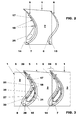
Figure 2 is a schematic cross section at the middle of the airfoil portions of the blade in the embodiment offigure 1 ; -
Figure 3 is a schematic cross section similar to that offigure 2 , with a number of blades one adjacent to the other; -
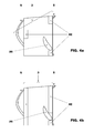
Figure 4 is a schematic front view of a blade in a second embodiment of the invention; -
Figure 4a is a schematic view from the bottom of the blade offigure 4 ; -
Figure 4b is a schematic view from the bottom of a blade similar to the blade offigure 4 but having a different root; -
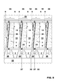
Figure 5 shows a schematic front view of a number of blades offigure 1 one adjacent to the other; -
Figure 6 is a schematic front view of a blade in a further embodiment of the invention without the shroud; -
Figures 7-9 show different embodiments of gaps between airfoil portions of adjacent blades; -
Figure 10 shows a particular embodiment of spacers between adjacent airfoil portions; and -
Figure 11 shows blades with platforms different from those offigure 1 with a sealing plate inbetween. - In the following reference to a rotor blade of a gas turbine will be made; it is anyhow clear that in different embodiments of the invention the blade could also be a guide vane of a gas turbine or in even further embodiments also a rotor or stator blade of a steam turbine or different rotating machine.
- With particular reference to
figure 1 , aturbine blade 1 is shown comprising aplatform 2 provided with aroot 3 arranged to be connected to a blade carrier (not shown infigure 1 but indicated by 22 infigure 5 ). - From the opposite sides of the
platform 2 of theblade 1,airfoil portions - Each airfoil portion defines one
operating surface - In this respect, with reference to
figures 2 and 3 , thesurface 8 of theairfoil portion 6 that faces theother airfoil portion 5 of thesame blade 1 is an operating surface of theblade 1, i.e. a surface that, when the blade is assembled in a gas turbine and during operation of the same gas turbine is arranged to come into contact with the hot gases flowing into the hot gases path. - Likewise,
figure 2 shows theoperating surface 7 of theairfoil portion 5 being the surface of theairfoil 5 facing theother airfoil portion 6 of thesame blade 1 and arranged to come into contact with the hot gases during operation. - In particular, the
operating surface 7 of theairfoil portions 5 defines a suction side and theoperating surface 8 of theairfoil portion 6 defines a pressure side of airfoils to be defined when a number ofblades 1 are connected each other. - The
blade 1 also comprises ashroud 10 connected at the ends of eachairfoil portion platform 2 with theairfoil portions shroud 10 define a closedchannel 11. - The
surfaces airfoil portions operating surfaces inner surfaces - Since during manufacturing these
inner surfaces heat transfer enhancers 17 is easier and cheaper than in traditional blades. - For example the
heat transfer enhancers 17 are ribs or pins or fins arranged to increase thermal exchanges extending from theinner surfaces 14 and/or 15. - Moreover, preferably the
inner surfaces airfoil portions 5 and/or 6 comprisespacers 18, such that when a number ofblades 1 are assembled on a blade carrier one adjacent to the other, thespacers 18 are interposed between twoadjacent airfoil portions -
Figure 10 shows a preferred embodiment of thespacers 18; in this embodiment both theblade portion spacer 18; these spacers are slidingly connected each other. - At least one of the
airfoil portions holes 20 arranged to let cooling air passing therethrough. -
Figures 1 and4 show only theairfoil portion 6 provided with these through holes, it is anyhow clear that in different embodiments bothairfoil portions holes 20 or only theairfoil portion 5 may have the throughholes 20. - In addition, in even further embodiments, the through
holes 20 may also be provided at theplatform 2 and/or at theshroud 10. -
Figures 3 and5 show ablade 1 connected toother blades 1, assembled onto ablade carrier 22. - As shown in these figures, the
airfoil portion 6 withoperating surface 8 defining a pressure side of ablade 1 is connected to anairfoil portion 5 withoperating surface 7 defining a suction side of a different,adjacent blade 1; the twoairfoils portions adjacent blades 1 connected each other together define anairfoil 24. -
Figure 3 shows that between the connectedairfoil portions 5 and 6 (i.e. inside of eachairfoil 24 defined by them), achamber 25 is defined. - The lower part of the
chamber 25 is closed by theplatforms 2 of twoadjacent blades 1 and its upper part is closed by theshrouds 10 of twoadjacent blades 1. - The
platform 2 has preferably straight side borders to make it easier housing a seal (figure 2 ). - In different embodiments (
figure 11 ) theplatform 2 has its side borders shaped with a curved profile. - Likewise, the
shroud 10 has straight side borders to make it easier housing a seal. - In different embodiments also the
shroud 10 may have side borders shaped with a curved profile. - It is anyhow clear that the side borders of the platform and shroud may comprise every combination of the above cited types (for example platform with straight side borders and shroud with a curved profile or vice versa).
- The
chamber 25 may be empty or house the heat transfer enhancers (for example ribs and/or pins and/or fins 17) and/or thespacers 18. - In addition, the
chamber 25 may also house atubular insert 27 arranged to feed compressed cooling air inside of thechamber 25. - In particular the
tubular insert 27 passes through ahole 26 of theplatform 2 and has an end inside of thechamber 25 and an opposite end outside of thechamber 25, in theregion 28 of theroots 3 of the blades. - The
tubular insert 27 may have different shapes such as for example circular or oval shape, nevertheless it has preferably a shape similar to the inner profile of the inside surfaces 14 and 15. - Moreover, the
tubular insert 27 may be separated from theairfoil portions spacers 30 arranged to rest against theinner surfaces airfoil portions - In further embodiments the
tubular insert 27 may not be provided with thespacers 30; thespacers 30 could extend from theinner surfaces airfoil portions spacer 30 may have the same structure shown infigure 10 for thespacer 18. - The
tubular insert 27 has a number of calibrated throughholes 31, arranged to let the cooling air pass through, to control the cooling air passing therethrough and thus entering thechamber 25. - Between the adjacent borders of the
platforms 2 and shrouds 10 seals are provided. - With the blade in the embodiment shown in
figure 1 seals similar to traditional seals such as straight bar shapedplates 33 may be provided; these seals are inserted in facingslots 32 indented in the side borders of theplatform 2 andshroud 10. - In different embodiments (
figure 11 ) theplate 33 is substantially C-shaped and is inserted in facingslots 32 indented in the curved side borders ofadjacent platform 2 and shrouds 10. - In addition, the
blades 1 also compriseseals 34 at theshrouds 10 for preventing the hot gases from passing through the gap between theshrouds 10 and acasing 35 of the gas turbine. - As shown in
figure 3 , advantageously theairfoil portions gaps gaps tubular insert 27 into thechamber 25 may be injected. -
Figure 7 shows a first possible configuration for thegap 38 between theairfoil portions gap 38 defines a slit. -
Figure 8 shows a second possible configuration for thegap 38 between theairfoil portions gap 38 have astep 40 to define a kind of labyrinth seal. -
Figure 9 shows a third possible configuration for thegap 38 between theairfoil portions airfoil portion 5 has aspring 41, provided with throughholes 41a to let the air pass through; thespring 41 rests against theairfoil portion 6. - In other embodiments, instead of one spring, the
airfoil portion 5 may have a plurality of springs with slits between them; in addition thesprings 41 may also be connected to theairfoil portion 6 and have its end resting against theairfoil portion 5 or, when a plurality ofsprings 41 are provided, some of them may be connected to theairfoil portion 5 and other to theairfoil portion 6. - The
gap 39 may have the same configuration as thegap 38 or also a different configuration similar to those already described with reference to thegap 38. - The operation of the
blade 1 is apparent from what described and illustrated and is substantially the following. - The hot gases, generated in a combustion chamber by burning a mixture of compressed air coming from a compressor and fuel, are expanded in the turbine.
- In particular, in the turbine the hot gases, driven by the guide vane, pass through the
rotor blades 1. - When passing through the
rotor blades 1, the hot gases pass through thechannels 11 defined between theplatform 2, theairfoil portions shroud 10, delivering mechanical power to the rotor. - While passing through the
channels 11 the aerodynamic losses are low (when compared to similar traditional blades) because the amount of purge air injected is reduced. - In addition, there is no hot gases leakage from the pressure side to the suction side at the tip of the
airfoils 24 thanks to theshrouds 10. - Therefore the total efficiency of the blade is increased when compared to similar traditional blades.
- Moreover, because of the particular structure with the
inner surfaces airfoil portions blades 1 are assembled onto the blade carrier 22) manufacturing is simple, quick and cheap when compared to manufacturing of traditional blades. - Thus it is particularly easy manufacturing of the heat transfer enhancers 17 (for example ribs and/or pins and/or fins) for increasing thermal exchanges.
- Moreover, also spacers 18 and 30 can be manufactured in an easy, cheap and fast way, and can for example be realised in one piece with the airfoil portions or may be manufactured separately and then connected thereto for example by brazing or welding.
- Thus, the
heat transfer enhancers 17 can be optimised in relation to the desired cooling effect instead of the manufacturing constrains; this lets the cooling problems to be sensibly reduced in comparison to similar traditional blades. - In addition, the shroud lets the vibration problems of the airfoils be reduced.
- The particular structure of the
airfoils 24 that are realised in two elements withinner surfaces - Also different embodiments of the invention are possible.
-
Figures 4 and4a shows a different embodiment with theroot 3 defined by three carryingribs 42 and figure 4c shows a further embodiments with theroot 3 defined by carryingribs 42. -
Figure 6 shows an embodiment of ablade 1 similar to the blade already described, in this respect the same references are used infigure 6 to define the same or similar elements. - In particular, the blade of
figure 6 has substantially the same features as the blade offigure 1 , but it is not provided with theshroud 10. - Naturally the features described may also be independently provided from one another.
- The turbine blade (being a rotor blade and/or a guide vane (i.e. a stator blade) conceived in this manner is susceptible to numerous modifications and variants, all falling within the scope of the inventive concept; moreover all details can be replaced by technically equivalent elements.
- In practice the materials used and the dimensions can be chosen at will according to requirements and to the state of the art.
-
- 1
- turbine blade
- 2
- platform
- 3
- root
- 5
- airfoil portion
- 6
- airfoil portion
- 7
- operating surface of 5
- 8
- operating surface of 6
- 10
- shroud
- 11
- channel
- 14
- inner surface of 5
- 15
- inner surface of 6
- 17
- heat transfer enhancers
- 18
- spacers
- 20
- through holes
- 22
- blade carrier
- 24
- airfoil
- 25
- chamber
- 26
- hole
- 27
- tubular insert
- 28
- region of the roots
- 30
- spacers
- 31
- calibrated through holes
- 32
- slots
- 33
- plates
- 34
- seals
- 35
- casing
- 38
- gap at the leading edge
- 39
- gap at the trailing edge
- 40
- steps
- 41
- springs
- 41a
- through holes
- 42
- carrying ribs
Claims (14)
- Blade (1) comprising a platform (2) and at least a root (3) arranged to be connected to a blade carrier (22), characterised in that, from the opposite sides of the platform (2), airfoil portions (5, 6) extend, each defining one operating surface (7, 8) being the surface facing the other airfoil portion (6, 5), wherein an operating surface (7, 8) of one of the airfoil portions (5, 6) defines a suction side and the other operating surface of the other airfoil portion defines a pressure side.
- Blade (1) as claimed in claim 1, characterised by comprising a shroud (10) connected at the ends of the airfoil portions (5, 6), wherein the platform (2) with the airfoil portions (5, 6) and the shroud (10) define a closed channel (11).
- Blade (1) as claimed in one or more of the previous claims, characterised in that a surface of each airfoil portion (5, 6) opposite the operating surface (7, 8) defines an inner surface (14, 15) of an airfoil (24) that, when a number of blades (1) are assembled on a blade carrier (22), is defined by two adjacent airfoil portions (5, 6).
- Blade (1) as claimed in one or more of the previous claims, characterised in that the inner surface (14, 15) of at least one of the airfoil portions (5, 6) has heat transfer enhancers (17) arranged to increase thermal exchanges.
- Blade (1) as claimed in one or more of the previous claims, characterised in that the inner surface (14, 15) of at least one of the airfoil portions (5, 6) comprises spacers (18, 30), such that when a number of blades (1) are assembled on a blade carrier (22), the spacers (18, 30) are interposed between two adjacent airfoil portions (5, 6).
- Blade (1) as claimed in one or more of the previous claims, characterised in that at least one of the airfoil portions (5, 6) and/or platform (2) and/or shroud (10) has through holes (20) arranged to let cooling air passing therethrough.
- Blade (1) as claimed in one or more of the previous claims, characterised by being assembled onto a blade carrier (22) adjacent to other blades (1), wherein an airfoil portion (6) with operating surface defining a pressure side of a blade (1) is connected to an airfoil portion (5) with operating surface defining a suction side of an adjacent blade (1).
- Blade (1) as claimed in one or more of the previous claims, characterised in that, between the adjacent airfoil portions (5, 6), a chamber (25) is defined.
- Blade (1) as claimed in one or more of the previous claims, characterised by comprising a tubular insert (27) having an end inside of the chamber (25) and an opposite end outside of the chamber (25) in the region (28) of the roots (3) of the blades (1).
- Blade (1) as claimed in one or more of the previous claims, characterised in that the tubular insert (27) has a number of calibrated through holes (31) arranged to control the cooling air entering the chamber (25).
- Blade (1) as claimed in one or more of the previous claims, characterised in that the platform (2) has a hole (26) to let the tubular insert pass through.
- Blade (1) as claimed in one or more of the previous claims, characterised by comprising seals (32, 33) provided at the side borders of the platform (2) and/or at the side borders of the shroud (10).
- Blade (1) as claimed in one or more of the previous claims, characterised by comprising seals (34) at the shrouds (10).
- Blade (1) as claimed in one or more of the previous claims, characterised by being a rotor blade or a guide vane.
Priority Applications (4)
| Application Number | Priority Date | Filing Date | Title |
|---|---|---|---|
| EP20090177829 EP2333240B1 (en) | 2009-12-03 | 2009-12-03 | Two-part turbine blade with improved cooling and vibrational characteristics |
| JP2010268897A JP5777330B2 (en) | 2009-12-03 | 2010-12-02 | Turbine blade |
| US12/958,727 US9017035B2 (en) | 2009-12-03 | 2010-12-02 | Turbine blade |
| CN201010585344.5A CN102102542B (en) | 2009-12-03 | 2010-12-03 | Turbine blade |
Applications Claiming Priority (1)
| Application Number | Priority Date | Filing Date | Title |
|---|---|---|---|
| EP20090177829 EP2333240B1 (en) | 2009-12-03 | 2009-12-03 | Two-part turbine blade with improved cooling and vibrational characteristics |
Publications (2)
| Publication Number | Publication Date |
|---|---|
| EP2333240A1 true EP2333240A1 (en) | 2011-06-15 |
| EP2333240B1 EP2333240B1 (en) | 2013-02-13 |
Family
ID=42126048
Family Applications (1)
| Application Number | Title | Priority Date | Filing Date |
|---|---|---|---|
| EP20090177829 Not-in-force EP2333240B1 (en) | 2009-12-03 | 2009-12-03 | Two-part turbine blade with improved cooling and vibrational characteristics |
Country Status (4)
| Country | Link |
|---|---|
| US (1) | US9017035B2 (en) |
| EP (1) | EP2333240B1 (en) |
| JP (1) | JP5777330B2 (en) |
| CN (1) | CN102102542B (en) |
Cited By (4)
| Publication number | Priority date | Publication date | Assignee | Title |
|---|---|---|---|---|
| WO2014029728A1 (en) * | 2012-08-20 | 2014-02-27 | Alstom Technology Ltd | Internally cooled airfoil for a rotary machine |
| WO2018044270A1 (en) * | 2016-08-30 | 2018-03-08 | Siemens Aktiengesellschaft | Segment for a turbine rotor stage |
| WO2018044271A1 (en) * | 2016-08-30 | 2018-03-08 | Siemens Aktiengesellschaft | Flow directing structure for a turbine stator stage |
| EP4083378A1 (en) * | 2021-03-29 | 2022-11-02 | Raytheon Technologies Corporation | Airfoil assembly with fiber-reinforced composite rings |
Families Citing this family (12)
| Publication number | Priority date | Publication date | Assignee | Title |
|---|---|---|---|---|
| FR2984786B1 (en) * | 2011-12-23 | 2014-01-03 | Snecma | METHOD FOR MANUFACTURING A HOLLOW DAWN |
| JP2013213427A (en) * | 2012-04-02 | 2013-10-17 | Toshiba Corp | Hollow nozzle and manufacturing method thereof |
| CN103742203B (en) * | 2014-02-11 | 2016-04-27 | 上海电气电站设备有限公司 | Steam turbine final blade |
| US20160281517A1 (en) * | 2015-03-26 | 2016-09-29 | Solar Turbines Incorporated | Cast nozzle with split airfoil |
| US10662782B2 (en) * | 2016-11-17 | 2020-05-26 | Raytheon Technologies Corporation | Airfoil with airfoil piece having axial seal |
| CN106593544A (en) * | 2017-01-23 | 2017-04-26 | 中国航发沈阳发动机研究所 | Tail edge cooling structure of turbine rotor blade and engine with tail edge cooling structure |
| GB201720829D0 (en) | 2017-12-14 | 2018-01-31 | Rolls Royce Plc | Aerofoil and method of manufacture |
| GB201720828D0 (en) | 2017-12-14 | 2018-01-31 | Rolls Royce Plc | Aerofoil |
| FR3108667B1 (en) * | 2020-03-27 | 2022-08-12 | Safran Ceram | Turbine stator blade made of ceramic matrix composite material |
| US11365636B2 (en) * | 2020-05-25 | 2022-06-21 | General Electric Company | Fan blade with intrinsic damping characteristics |
| US11549378B1 (en) | 2022-06-03 | 2023-01-10 | Raytheon Technologies Corporation | Airfoil assembly with composite rings and sealing shelf |
| FR3153371A1 (en) * | 2023-09-26 | 2025-03-28 | Safran Aircraft Engines | BLADE FOR A TURBOMACHINE ROTOR AND ASSOCIATED TURBOMACHINE ROTOR |
Citations (4)
| Publication number | Priority date | Publication date | Assignee | Title |
|---|---|---|---|---|
| US2930580A (en) * | 1953-03-12 | 1960-03-29 | Gen Motors Corp | Two-piece turbine bucket |
| WO2000053895A1 (en) * | 1999-03-11 | 2000-09-14 | Alm Development, Inc. | Turbine rotor disk |
| US6331217B1 (en) * | 1997-10-27 | 2001-12-18 | Siemens Westinghouse Power Corporation | Turbine blades made from multiple single crystal cast superalloy segments |
| US6382908B1 (en) * | 2001-01-18 | 2002-05-07 | General Electric Company | Nozzle fillet backside cooling |
Family Cites Families (13)
| Publication number | Priority date | Publication date | Assignee | Title |
|---|---|---|---|---|
| GB2028928B (en) | 1978-08-17 | 1982-08-25 | Ross Royce Ltd | Aerofoil blade for a gas turbine engine |
| JPH0510102A (en) | 1991-07-02 | 1993-01-19 | Hitachi Ltd | Gas turbine blade and gas turbine device |
| US5203873A (en) | 1991-08-29 | 1993-04-20 | General Electric Company | Turbine blade impingement baffle |
| CN1162345A (en) | 1994-10-31 | 1997-10-15 | 西屋电气公司 | Gas turbine blades with cooled platforms |
| ES2118638T3 (en) | 1994-10-31 | 1998-09-16 | Westinghouse Electric Corp | GAS TURBINE ROTARY ALABE WITH REFRIGERATED PLATFORM. |
| US6257830B1 (en) * | 1997-06-06 | 2001-07-10 | Mitsubishi Heavy Industries, Ltd. | Gas turbine blade |
| EP1191189A1 (en) * | 2000-09-26 | 2002-03-27 | Siemens Aktiengesellschaft | Gas turbine blades |
| JP2003214107A (en) | 2002-01-25 | 2003-07-30 | Mitsubishi Heavy Ind Ltd | Axial flow turbine blade, gas turbine using the same and axial flow compressor |
| US6742991B2 (en) | 2002-07-11 | 2004-06-01 | Mitsubishi Heavy Industries, Ltd. | Turbine blade and gas turbine |
| US7094031B2 (en) * | 2004-09-09 | 2006-08-22 | General Electric Company | Offset Coriolis turbulator blade |
| JP2006242050A (en) | 2005-03-02 | 2006-09-14 | Mitsubishi Heavy Ind Ltd | Blade cooling structure for gas turbine |
| US7371049B2 (en) * | 2005-08-31 | 2008-05-13 | United Technologies Corporation | Manufacturable and inspectable microcircuit cooling for blades |
| US7322796B2 (en) | 2005-08-31 | 2008-01-29 | United Technologies Corporation | Turbine vane construction |
-
2009
- 2009-12-03 EP EP20090177829 patent/EP2333240B1/en not_active Not-in-force
-
2010
- 2010-12-02 JP JP2010268897A patent/JP5777330B2/en not_active Expired - Fee Related
- 2010-12-02 US US12/958,727 patent/US9017035B2/en not_active Expired - Fee Related
- 2010-12-03 CN CN201010585344.5A patent/CN102102542B/en not_active Expired - Fee Related
Patent Citations (4)
| Publication number | Priority date | Publication date | Assignee | Title |
|---|---|---|---|---|
| US2930580A (en) * | 1953-03-12 | 1960-03-29 | Gen Motors Corp | Two-piece turbine bucket |
| US6331217B1 (en) * | 1997-10-27 | 2001-12-18 | Siemens Westinghouse Power Corporation | Turbine blades made from multiple single crystal cast superalloy segments |
| WO2000053895A1 (en) * | 1999-03-11 | 2000-09-14 | Alm Development, Inc. | Turbine rotor disk |
| US6382908B1 (en) * | 2001-01-18 | 2002-05-07 | General Electric Company | Nozzle fillet backside cooling |
Cited By (7)
| Publication number | Priority date | Publication date | Assignee | Title |
|---|---|---|---|---|
| WO2014029728A1 (en) * | 2012-08-20 | 2014-02-27 | Alstom Technology Ltd | Internally cooled airfoil for a rotary machine |
| US9890646B2 (en) | 2012-08-20 | 2018-02-13 | Ansaldo Energia Ip Uk Limited | Internally cooled airfoil for a rotary machine |
| WO2018044270A1 (en) * | 2016-08-30 | 2018-03-08 | Siemens Aktiengesellschaft | Segment for a turbine rotor stage |
| WO2018044271A1 (en) * | 2016-08-30 | 2018-03-08 | Siemens Aktiengesellschaft | Flow directing structure for a turbine stator stage |
| EP4083378A1 (en) * | 2021-03-29 | 2022-11-02 | Raytheon Technologies Corporation | Airfoil assembly with fiber-reinforced composite rings |
| US11898463B2 (en) | 2021-03-29 | 2024-02-13 | Rtx Corporation | Airfoil assembly with fiber-reinforced composite rings |
| EP4361401A3 (en) * | 2021-03-29 | 2024-07-03 | RTX Corporation | Airfoil assembly with fiber-reinforced composite rings |
Also Published As
| Publication number | Publication date |
|---|---|
| CN102102542B (en) | 2016-02-10 |
| JP5777330B2 (en) | 2015-09-09 |
| US9017035B2 (en) | 2015-04-28 |
| EP2333240B1 (en) | 2013-02-13 |
| CN102102542A (en) | 2011-06-22 |
| JP2011122588A (en) | 2011-06-23 |
| US20110135497A1 (en) | 2011-06-09 |
Similar Documents
| Publication | Publication Date | Title |
|---|---|---|
| EP2333240B1 (en) | Two-part turbine blade with improved cooling and vibrational characteristics | |
| CN103422908B (en) | Cooling structure in the end of turbine rotor blade | |
| CN103422909B (en) | Cooling structure in the end of turbine rotor blade | |
| US8720207B2 (en) | Gas turbine stator/rotor expansion stage having bumps arranged to locally increase static pressure | |
| CN105937410B (en) | turbine rotor blades | |
| US8348602B2 (en) | Turbomachine turbine ring sector | |
| CN204253116U (en) | For the protective housing sections of combustion gas turbine shell | |
| CN102562169B (en) | Gas turbine of the axial flow type | |
| CN102477871B (en) | The gas turbine of axial flow | |
| EP2204545A2 (en) | Nozzles with stress reducing pockets and gas turbine engine | |
| CA2552214A1 (en) | Blades for a gas turbine engine with integrated sealing plate and method | |
| CN102477873B (en) | The gas turbine of axial flow | |
| US20160169052A1 (en) | Rotating gas turbine blade and gas turbine with such a blade | |
| US9932837B2 (en) | Low pressure loss cooled blade | |
| US9528380B2 (en) | Turbine bucket and method for cooling a turbine bucket of a gas turbine engine | |
| CN104520538B (en) | Turbine blade | |
| EP2530244B1 (en) | A stator assembly for surrounding a rotor and a method of cooling | |
| US10738638B2 (en) | Rotor blade with wheel space swirlers and method for forming a rotor blade with wheel space swirlers | |
| CN105715307B (en) | Arrangement of a rotor and at least one blade | |
| WO2013148403A1 (en) | Turbine nozzle | |
| US20120315139A1 (en) | Cooling flow control members for turbomachine buckets and method |
Legal Events
| Date | Code | Title | Description |
|---|---|---|---|
| PUAI | Public reference made under article 153(3) epc to a published international application that has entered the european phase |
Free format text: ORIGINAL CODE: 0009012 |
|
| AK | Designated contracting states |
Kind code of ref document: A1 Designated state(s): AT BE BG CH CY CZ DE DK EE ES FI FR GB GR HR HU IE IS IT LI LT LU LV MC MK MT NL NO PL PT RO SE SI SK SM TR |
|
| AX | Request for extension of the european patent |
Extension state: AL BA RS |
|
| 17P | Request for examination filed |
Effective date: 20111212 |
|
| 17Q | First examination report despatched |
Effective date: 20120202 |
|
| GRAP | Despatch of communication of intention to grant a patent |
Free format text: ORIGINAL CODE: EPIDOSNIGR1 |
|
| GRAS | Grant fee paid |
Free format text: ORIGINAL CODE: EPIDOSNIGR3 |
|
| GRAA | (expected) grant |
Free format text: ORIGINAL CODE: 0009210 |
|
| AK | Designated contracting states |
Kind code of ref document: B1 Designated state(s): AT BE BG CH CY CZ DE DK EE ES FI FR GB GR HR HU IE IS IT LI LT LU LV MC MK MT NL NO PL PT RO SE SI SK SM TR |
|
| REG | Reference to a national code |
Ref country code: GB Ref legal event code: FG4D |
|
| REG | Reference to a national code |
Ref country code: AT Ref legal event code: REF Ref document number: 596619 Country of ref document: AT Kind code of ref document: T Effective date: 20130215 |
|
| REG | Reference to a national code |
Ref country code: IE Ref legal event code: FG4D |
|
| REG | Reference to a national code |
Ref country code: DE Ref legal event code: R096 Ref document number: 602009013218 Country of ref document: DE Effective date: 20130411 |
|
| REG | Reference to a national code |
Ref country code: AT Ref legal event code: MK05 Ref document number: 596619 Country of ref document: AT Kind code of ref document: T Effective date: 20130213 |
|
| REG | Reference to a national code |
Ref country code: NL Ref legal event code: VDEP Effective date: 20130213 |
|
| REG | Reference to a national code |
Ref country code: LT Ref legal event code: MG4D |
|
| PG25 | Lapsed in a contracting state [announced via postgrant information from national office to epo] |
Ref country code: ES Free format text: LAPSE BECAUSE OF FAILURE TO SUBMIT A TRANSLATION OF THE DESCRIPTION OR TO PAY THE FEE WITHIN THE PRESCRIBED TIME-LIMIT Effective date: 20130524 Ref country code: LT Free format text: LAPSE BECAUSE OF FAILURE TO SUBMIT A TRANSLATION OF THE DESCRIPTION OR TO PAY THE FEE WITHIN THE PRESCRIBED TIME-LIMIT Effective date: 20130213 Ref country code: IS Free format text: LAPSE BECAUSE OF FAILURE TO SUBMIT A TRANSLATION OF THE DESCRIPTION OR TO PAY THE FEE WITHIN THE PRESCRIBED TIME-LIMIT Effective date: 20130613 Ref country code: NO Free format text: LAPSE BECAUSE OF FAILURE TO SUBMIT A TRANSLATION OF THE DESCRIPTION OR TO PAY THE FEE WITHIN THE PRESCRIBED TIME-LIMIT Effective date: 20130513 Ref country code: AT Free format text: LAPSE BECAUSE OF FAILURE TO SUBMIT A TRANSLATION OF THE DESCRIPTION OR TO PAY THE FEE WITHIN THE PRESCRIBED TIME-LIMIT Effective date: 20130213 Ref country code: SE Free format text: LAPSE BECAUSE OF FAILURE TO SUBMIT A TRANSLATION OF THE DESCRIPTION OR TO PAY THE FEE WITHIN THE PRESCRIBED TIME-LIMIT Effective date: 20130213 Ref country code: BG Free format text: LAPSE BECAUSE OF FAILURE TO SUBMIT A TRANSLATION OF THE DESCRIPTION OR TO PAY THE FEE WITHIN THE PRESCRIBED TIME-LIMIT Effective date: 20130513 |
|
| PG25 | Lapsed in a contracting state [announced via postgrant information from national office to epo] |
Ref country code: GR Free format text: LAPSE BECAUSE OF FAILURE TO SUBMIT A TRANSLATION OF THE DESCRIPTION OR TO PAY THE FEE WITHIN THE PRESCRIBED TIME-LIMIT Effective date: 20130514 Ref country code: BE Free format text: LAPSE BECAUSE OF FAILURE TO SUBMIT A TRANSLATION OF THE DESCRIPTION OR TO PAY THE FEE WITHIN THE PRESCRIBED TIME-LIMIT Effective date: 20130213 Ref country code: FI Free format text: LAPSE BECAUSE OF FAILURE TO SUBMIT A TRANSLATION OF THE DESCRIPTION OR TO PAY THE FEE WITHIN THE PRESCRIBED TIME-LIMIT Effective date: 20130213 Ref country code: SI Free format text: LAPSE BECAUSE OF FAILURE TO SUBMIT A TRANSLATION OF THE DESCRIPTION OR TO PAY THE FEE WITHIN THE PRESCRIBED TIME-LIMIT Effective date: 20130213 Ref country code: PL Free format text: LAPSE BECAUSE OF FAILURE TO SUBMIT A TRANSLATION OF THE DESCRIPTION OR TO PAY THE FEE WITHIN THE PRESCRIBED TIME-LIMIT Effective date: 20130213 Ref country code: PT Free format text: LAPSE BECAUSE OF FAILURE TO SUBMIT A TRANSLATION OF THE DESCRIPTION OR TO PAY THE FEE WITHIN THE PRESCRIBED TIME-LIMIT Effective date: 20130613 Ref country code: LV Free format text: LAPSE BECAUSE OF FAILURE TO SUBMIT A TRANSLATION OF THE DESCRIPTION OR TO PAY THE FEE WITHIN THE PRESCRIBED TIME-LIMIT Effective date: 20130213 |
|
| PG25 | Lapsed in a contracting state [announced via postgrant information from national office to epo] |
Ref country code: HR Free format text: LAPSE BECAUSE OF FAILURE TO SUBMIT A TRANSLATION OF THE DESCRIPTION OR TO PAY THE FEE WITHIN THE PRESCRIBED TIME-LIMIT Effective date: 20130213 |
|
| PG25 | Lapsed in a contracting state [announced via postgrant information from national office to epo] |
Ref country code: EE Free format text: LAPSE BECAUSE OF FAILURE TO SUBMIT A TRANSLATION OF THE DESCRIPTION OR TO PAY THE FEE WITHIN THE PRESCRIBED TIME-LIMIT Effective date: 20130213 Ref country code: CZ Free format text: LAPSE BECAUSE OF FAILURE TO SUBMIT A TRANSLATION OF THE DESCRIPTION OR TO PAY THE FEE WITHIN THE PRESCRIBED TIME-LIMIT Effective date: 20130213 Ref country code: RO Free format text: LAPSE BECAUSE OF FAILURE TO SUBMIT A TRANSLATION OF THE DESCRIPTION OR TO PAY THE FEE WITHIN THE PRESCRIBED TIME-LIMIT Effective date: 20130213 Ref country code: DK Free format text: LAPSE BECAUSE OF FAILURE TO SUBMIT A TRANSLATION OF THE DESCRIPTION OR TO PAY THE FEE WITHIN THE PRESCRIBED TIME-LIMIT Effective date: 20130213 Ref country code: SK Free format text: LAPSE BECAUSE OF FAILURE TO SUBMIT A TRANSLATION OF THE DESCRIPTION OR TO PAY THE FEE WITHIN THE PRESCRIBED TIME-LIMIT Effective date: 20130213 Ref country code: NL Free format text: LAPSE BECAUSE OF FAILURE TO SUBMIT A TRANSLATION OF THE DESCRIPTION OR TO PAY THE FEE WITHIN THE PRESCRIBED TIME-LIMIT Effective date: 20130213 |
|
| PLBE | No opposition filed within time limit |
Free format text: ORIGINAL CODE: 0009261 |
|
| STAA | Information on the status of an ep patent application or granted ep patent |
Free format text: STATUS: NO OPPOSITION FILED WITHIN TIME LIMIT |
|
| PG25 | Lapsed in a contracting state [announced via postgrant information from national office to epo] |
Ref country code: IT Free format text: LAPSE BECAUSE OF FAILURE TO SUBMIT A TRANSLATION OF THE DESCRIPTION OR TO PAY THE FEE WITHIN THE PRESCRIBED TIME-LIMIT Effective date: 20130213 |
|
| 26N | No opposition filed |
Effective date: 20131114 |
|
| REG | Reference to a national code |
Ref country code: DE Ref legal event code: R097 Ref document number: 602009013218 Country of ref document: DE Effective date: 20131114 |
|
| REG | Reference to a national code |
Ref country code: CH Ref legal event code: PL |
|
| PG25 | Lapsed in a contracting state [announced via postgrant information from national office to epo] |
Ref country code: MC Free format text: LAPSE BECAUSE OF FAILURE TO SUBMIT A TRANSLATION OF THE DESCRIPTION OR TO PAY THE FEE WITHIN THE PRESCRIBED TIME-LIMIT Effective date: 20130213 Ref country code: LU Free format text: LAPSE BECAUSE OF FAILURE TO SUBMIT A TRANSLATION OF THE DESCRIPTION OR TO PAY THE FEE WITHIN THE PRESCRIBED TIME-LIMIT Effective date: 20131203 |
|
| REG | Reference to a national code |
Ref country code: IE Ref legal event code: MM4A |
|
| PG25 | Lapsed in a contracting state [announced via postgrant information from national office to epo] |
Ref country code: CH Free format text: LAPSE BECAUSE OF NON-PAYMENT OF DUE FEES Effective date: 20131231 Ref country code: IE Free format text: LAPSE BECAUSE OF NON-PAYMENT OF DUE FEES Effective date: 20131203 Ref country code: LI Free format text: LAPSE BECAUSE OF NON-PAYMENT OF DUE FEES Effective date: 20131231 |
|
| PG25 | Lapsed in a contracting state [announced via postgrant information from national office to epo] |
Ref country code: SM Free format text: LAPSE BECAUSE OF FAILURE TO SUBMIT A TRANSLATION OF THE DESCRIPTION OR TO PAY THE FEE WITHIN THE PRESCRIBED TIME-LIMIT Effective date: 20130213 |
|
| PG25 | Lapsed in a contracting state [announced via postgrant information from national office to epo] |
Ref country code: CY Free format text: LAPSE BECAUSE OF FAILURE TO SUBMIT A TRANSLATION OF THE DESCRIPTION OR TO PAY THE FEE WITHIN THE PRESCRIBED TIME-LIMIT Effective date: 20130213 Ref country code: TR Free format text: LAPSE BECAUSE OF FAILURE TO SUBMIT A TRANSLATION OF THE DESCRIPTION OR TO PAY THE FEE WITHIN THE PRESCRIBED TIME-LIMIT Effective date: 20130213 |
|
| PG25 | Lapsed in a contracting state [announced via postgrant information from national office to epo] |
Ref country code: MK Free format text: LAPSE BECAUSE OF FAILURE TO SUBMIT A TRANSLATION OF THE DESCRIPTION OR TO PAY THE FEE WITHIN THE PRESCRIBED TIME-LIMIT Effective date: 20130213 Ref country code: HU Free format text: LAPSE BECAUSE OF FAILURE TO SUBMIT A TRANSLATION OF THE DESCRIPTION OR TO PAY THE FEE WITHIN THE PRESCRIBED TIME-LIMIT; INVALID AB INITIO Effective date: 20091203 |
|
| PG25 | Lapsed in a contracting state [announced via postgrant information from national office to epo] |
Ref country code: MT Free format text: LAPSE BECAUSE OF FAILURE TO SUBMIT A TRANSLATION OF THE DESCRIPTION OR TO PAY THE FEE WITHIN THE PRESCRIBED TIME-LIMIT Effective date: 20130213 |
|
| REG | Reference to a national code |
Ref country code: FR Ref legal event code: PLFP Year of fee payment: 7 |
|
| REG | Reference to a national code |
Ref country code: DE Ref legal event code: R081 Ref document number: 602009013218 Country of ref document: DE Owner name: GENERAL ELECTRIC TECHNOLOGY GMBH, CH Free format text: FORMER OWNER: ALSTOM TECHNOLOGY LTD., BADEN, CH Ref country code: DE Ref legal event code: R081 Ref document number: 602009013218 Country of ref document: DE Owner name: ANSALDO ENERGIA IP UK LIMITED, GB Free format text: FORMER OWNER: ALSTOM TECHNOLOGY LTD., BADEN, CH |
|
| REG | Reference to a national code |
Ref country code: FR Ref legal event code: CD Owner name: ALSTOM TECHNOLOGY LTD, CH Effective date: 20161110 |
|
| REG | Reference to a national code |
Ref country code: FR Ref legal event code: PLFP Year of fee payment: 8 |
|
| PGFP | Annual fee paid to national office [announced via postgrant information from national office to epo] |
Ref country code: GB Payment date: 20161222 Year of fee payment: 8 |
|
| REG | Reference to a national code |
Ref country code: DE Ref legal event code: R081 Ref document number: 602009013218 Country of ref document: DE Owner name: ANSALDO ENERGIA IP UK LIMITED, GB Free format text: FORMER OWNER: GENERAL ELECTRIC TECHNOLOGY GMBH, BADEN, CH |
|
| REG | Reference to a national code |
Ref country code: GB Ref legal event code: 732E Free format text: REGISTERED BETWEEN 20170824 AND 20170830 |
|
| REG | Reference to a national code |
Ref country code: FR Ref legal event code: PLFP Year of fee payment: 9 |
|
| REG | Reference to a national code |
Ref country code: FR Ref legal event code: TP Owner name: ANSALDO ENERGIA IP UK LIMITED, GB Effective date: 20171221 |
|
| PGFP | Annual fee paid to national office [announced via postgrant information from national office to epo] |
Ref country code: FR Payment date: 20171221 Year of fee payment: 9 Ref country code: DE Payment date: 20171211 Year of fee payment: 9 |
|
| GBPC | Gb: european patent ceased through non-payment of renewal fee |
Effective date: 20171203 |
|
| PG25 | Lapsed in a contracting state [announced via postgrant information from national office to epo] |
Ref country code: GB Free format text: LAPSE BECAUSE OF NON-PAYMENT OF DUE FEES Effective date: 20171203 |
|
| REG | Reference to a national code |
Ref country code: DE Ref legal event code: R119 Ref document number: 602009013218 Country of ref document: DE |
|
| PG25 | Lapsed in a contracting state [announced via postgrant information from national office to epo] |
Ref country code: DE Free format text: LAPSE BECAUSE OF NON-PAYMENT OF DUE FEES Effective date: 20190702 Ref country code: FR Free format text: LAPSE BECAUSE OF NON-PAYMENT OF DUE FEES Effective date: 20181231 |