EP2332931A2 - Novel compound, method for preparing same and organic electronic device using same - Google Patents
Novel compound, method for preparing same and organic electronic device using same Download PDFInfo
- Publication number
- EP2332931A2 EP2332931A2 EP09816420A EP09816420A EP2332931A2 EP 2332931 A2 EP2332931 A2 EP 2332931A2 EP 09816420 A EP09816420 A EP 09816420A EP 09816420 A EP09816420 A EP 09816420A EP 2332931 A2 EP2332931 A2 EP 2332931A2
- Authority
- EP
- European Patent Office
- Prior art keywords
- group
- compound
- substituted
- unsubstituted
- heteroaryl
- Prior art date
- Legal status (The legal status is an assumption and is not a legal conclusion. Google has not performed a legal analysis and makes no representation as to the accuracy of the status listed.)
- Granted
Links
- 0 CC1(C)O*(C(CC=C2)*c3c2c(-c2ccccc2)c(cccc2)c2c3-c2ccccc2)OC1(C)C Chemical compound CC1(C)O*(C(CC=C2)*c3c2c(-c2ccccc2)c(cccc2)c2c3-c2ccccc2)OC1(C)C 0.000 description 17
- OHQCTGJLIOLWQR-COBSHVIPSA-N C1C2C=CC=[F]C[C@@H]12 Chemical compound C1C2C=CC=[F]C[C@@H]12 OHQCTGJLIOLWQR-COBSHVIPSA-N 0.000 description 1
- RFICEZUPPOXEDC-UHFFFAOYSA-N C1C=Cc2c(-c(cc3)ccc3C(C3C(c4c5[s]cc4-c4ccccc4)=CC=CC3)=C5c3ccccc3)c(cccc3)c3c(-c3c(cccc4)c4ccc3)c2C1 Chemical compound C1C=Cc2c(-c(cc3)ccc3C(C3C(c4c5[s]cc4-c4ccccc4)=CC=CC3)=C5c3ccccc3)c(cccc3)c3c(-c3c(cccc4)c4ccc3)c2C1 RFICEZUPPOXEDC-UHFFFAOYSA-N 0.000 description 1
- HXITXNWTGFUOAU-UHFFFAOYSA-N OB(c1ccccc1)O Chemical compound OB(c1ccccc1)O HXITXNWTGFUOAU-UHFFFAOYSA-N 0.000 description 1
- IVVTVUUKHICUPF-UHFFFAOYSA-N OS(c1ccccc1)O Chemical compound OS(c1ccccc1)O IVVTVUUKHICUPF-UHFFFAOYSA-N 0.000 description 1
Images


Classifications
-
- C—CHEMISTRY; METALLURGY
- C07—ORGANIC CHEMISTRY
- C07D—HETEROCYCLIC COMPOUNDS
- C07D333/00—Heterocyclic compounds containing five-membered rings having one sulfur atom as the only ring hetero atom
- C07D333/50—Heterocyclic compounds containing five-membered rings having one sulfur atom as the only ring hetero atom condensed with carbocyclic rings or ring systems
-
- C—CHEMISTRY; METALLURGY
- C09—DYES; PAINTS; POLISHES; NATURAL RESINS; ADHESIVES; COMPOSITIONS NOT OTHERWISE PROVIDED FOR; APPLICATIONS OF MATERIALS NOT OTHERWISE PROVIDED FOR
- C09K—MATERIALS FOR MISCELLANEOUS APPLICATIONS, NOT PROVIDED FOR ELSEWHERE
- C09K11/00—Luminescent materials, e.g. electroluminescent or chemiluminescent
- C09K11/06—Luminescent materials, e.g. electroluminescent or chemiluminescent containing organic luminescent materials
-
- C—CHEMISTRY; METALLURGY
- C07—ORGANIC CHEMISTRY
- C07D—HETEROCYCLIC COMPOUNDS
- C07D333/00—Heterocyclic compounds containing five-membered rings having one sulfur atom as the only ring hetero atom
- C07D333/50—Heterocyclic compounds containing five-membered rings having one sulfur atom as the only ring hetero atom condensed with carbocyclic rings or ring systems
- C07D333/74—Naphthothiophenes
-
- C—CHEMISTRY; METALLURGY
- C07—ORGANIC CHEMISTRY
- C07D—HETEROCYCLIC COMPOUNDS
- C07D209/00—Heterocyclic compounds containing five-membered rings, condensed with other rings, with one nitrogen atom as the only ring hetero atom
- C07D209/56—Ring systems containing three or more rings
- C07D209/80—[b, c]- or [b, d]-condensed
- C07D209/82—Carbazoles; Hydrogenated carbazoles
- C07D209/86—Carbazoles; Hydrogenated carbazoles with only hydrogen atoms, hydrocarbon or substituted hydrocarbon radicals, directly attached to carbon atoms of the ring system
-
- C—CHEMISTRY; METALLURGY
- C07—ORGANIC CHEMISTRY
- C07D—HETEROCYCLIC COMPOUNDS
- C07D263/00—Heterocyclic compounds containing 1,3-oxazole or hydrogenated 1,3-oxazole rings
- C07D263/52—Heterocyclic compounds containing 1,3-oxazole or hydrogenated 1,3-oxazole rings condensed with carbocyclic rings or ring systems
- C07D263/54—Benzoxazoles; Hydrogenated benzoxazoles
- C07D263/56—Benzoxazoles; Hydrogenated benzoxazoles with only hydrogen atoms, hydrocarbon or substituted hydrocarbon radicals, directly attached in position 2
- C07D263/57—Aryl or substituted aryl radicals
-
- C—CHEMISTRY; METALLURGY
- C07—ORGANIC CHEMISTRY
- C07D—HETEROCYCLIC COMPOUNDS
- C07D307/00—Heterocyclic compounds containing five-membered rings having one oxygen atom as the only ring hetero atom
- C07D307/77—Heterocyclic compounds containing five-membered rings having one oxygen atom as the only ring hetero atom ortho- or peri-condensed with carbocyclic rings or ring systems
-
- C—CHEMISTRY; METALLURGY
- C07—ORGANIC CHEMISTRY
- C07D—HETEROCYCLIC COMPOUNDS
- C07D307/00—Heterocyclic compounds containing five-membered rings having one oxygen atom as the only ring hetero atom
- C07D307/77—Heterocyclic compounds containing five-membered rings having one oxygen atom as the only ring hetero atom ortho- or peri-condensed with carbocyclic rings or ring systems
- C07D307/92—Naphthofurans; Hydrogenated naphthofurans
-
- C—CHEMISTRY; METALLURGY
- C07—ORGANIC CHEMISTRY
- C07D—HETEROCYCLIC COMPOUNDS
- C07D311/00—Heterocyclic compounds containing six-membered rings having one oxygen atom as the only hetero atom, condensed with other rings
- C07D311/02—Heterocyclic compounds containing six-membered rings having one oxygen atom as the only hetero atom, condensed with other rings ortho- or peri-condensed with carbocyclic rings or ring systems
- C07D311/04—Benzo[b]pyrans, not hydrogenated in the carbocyclic ring
-
- C—CHEMISTRY; METALLURGY
- C07—ORGANIC CHEMISTRY
- C07D—HETEROCYCLIC COMPOUNDS
- C07D333/00—Heterocyclic compounds containing five-membered rings having one sulfur atom as the only ring hetero atom
- C07D333/02—Heterocyclic compounds containing five-membered rings having one sulfur atom as the only ring hetero atom not condensed with other rings
- C07D333/04—Heterocyclic compounds containing five-membered rings having one sulfur atom as the only ring hetero atom not condensed with other rings not substituted on the ring sulphur atom
- C07D333/26—Heterocyclic compounds containing five-membered rings having one sulfur atom as the only ring hetero atom not condensed with other rings not substituted on the ring sulphur atom with hetero atoms or with carbon atoms having three bonds to hetero atoms with at the most one bond to halogen, e.g. ester or nitrile radicals, directly attached to ring carbon atoms
- C07D333/30—Hetero atoms other than halogen
- C07D333/36—Nitrogen atoms
-
- C—CHEMISTRY; METALLURGY
- C07—ORGANIC CHEMISTRY
- C07D—HETEROCYCLIC COMPOUNDS
- C07D333/00—Heterocyclic compounds containing five-membered rings having one sulfur atom as the only ring hetero atom
- C07D333/50—Heterocyclic compounds containing five-membered rings having one sulfur atom as the only ring hetero atom condensed with carbocyclic rings or ring systems
- C07D333/52—Benzo[b]thiophenes; Hydrogenated benzo[b]thiophenes
- C07D333/54—Benzo[b]thiophenes; Hydrogenated benzo[b]thiophenes with only hydrogen atoms, hydrocarbon or substituted hydrocarbon radicals, directly attached to carbon atoms of the hetero ring
-
- C—CHEMISTRY; METALLURGY
- C07—ORGANIC CHEMISTRY
- C07D—HETEROCYCLIC COMPOUNDS
- C07D403/00—Heterocyclic compounds containing two or more hetero rings, having nitrogen atoms as the only ring hetero atoms, not provided for by group C07D401/00
- C07D403/02—Heterocyclic compounds containing two or more hetero rings, having nitrogen atoms as the only ring hetero atoms, not provided for by group C07D401/00 containing two hetero rings
- C07D403/04—Heterocyclic compounds containing two or more hetero rings, having nitrogen atoms as the only ring hetero atoms, not provided for by group C07D401/00 containing two hetero rings directly linked by a ring-member-to-ring-member bond
-
- C—CHEMISTRY; METALLURGY
- C07—ORGANIC CHEMISTRY
- C07D—HETEROCYCLIC COMPOUNDS
- C07D405/00—Heterocyclic compounds containing both one or more hetero rings having oxygen atoms as the only ring hetero atoms, and one or more rings having nitrogen as the only ring hetero atom
- C07D405/02—Heterocyclic compounds containing both one or more hetero rings having oxygen atoms as the only ring hetero atoms, and one or more rings having nitrogen as the only ring hetero atom containing two hetero rings
- C07D405/10—Heterocyclic compounds containing both one or more hetero rings having oxygen atoms as the only ring hetero atoms, and one or more rings having nitrogen as the only ring hetero atom containing two hetero rings linked by a carbon chain containing aromatic rings
-
- C—CHEMISTRY; METALLURGY
- C07—ORGANIC CHEMISTRY
- C07D—HETEROCYCLIC COMPOUNDS
- C07D405/00—Heterocyclic compounds containing both one or more hetero rings having oxygen atoms as the only ring hetero atoms, and one or more rings having nitrogen as the only ring hetero atom
- C07D405/14—Heterocyclic compounds containing both one or more hetero rings having oxygen atoms as the only ring hetero atoms, and one or more rings having nitrogen as the only ring hetero atom containing three or more hetero rings
-
- C—CHEMISTRY; METALLURGY
- C07—ORGANIC CHEMISTRY
- C07D—HETEROCYCLIC COMPOUNDS
- C07D409/00—Heterocyclic compounds containing two or more hetero rings, at least one ring having sulfur atoms as the only ring hetero atoms
- C07D409/02—Heterocyclic compounds containing two or more hetero rings, at least one ring having sulfur atoms as the only ring hetero atoms containing two hetero rings
- C07D409/10—Heterocyclic compounds containing two or more hetero rings, at least one ring having sulfur atoms as the only ring hetero atoms containing two hetero rings linked by a carbon chain containing aromatic rings
-
- C—CHEMISTRY; METALLURGY
- C07—ORGANIC CHEMISTRY
- C07D—HETEROCYCLIC COMPOUNDS
- C07D409/00—Heterocyclic compounds containing two or more hetero rings, at least one ring having sulfur atoms as the only ring hetero atoms
- C07D409/14—Heterocyclic compounds containing two or more hetero rings, at least one ring having sulfur atoms as the only ring hetero atoms containing three or more hetero rings
-
- C—CHEMISTRY; METALLURGY
- C07—ORGANIC CHEMISTRY
- C07D—HETEROCYCLIC COMPOUNDS
- C07D471/00—Heterocyclic compounds containing nitrogen atoms as the only ring hetero atoms in the condensed system, at least one ring being a six-membered ring with one nitrogen atom, not provided for by groups C07D451/00 - C07D463/00
- C07D471/02—Heterocyclic compounds containing nitrogen atoms as the only ring hetero atoms in the condensed system, at least one ring being a six-membered ring with one nitrogen atom, not provided for by groups C07D451/00 - C07D463/00 in which the condensed system contains two hetero rings
- C07D471/04—Ortho-condensed systems
-
- H—ELECTRICITY
- H10—SEMICONDUCTOR DEVICES; ELECTRIC SOLID-STATE DEVICES NOT OTHERWISE PROVIDED FOR
- H10K—ORGANIC ELECTRIC SOLID-STATE DEVICES
- H10K85/00—Organic materials used in the body or electrodes of devices covered by this subclass
- H10K85/30—Coordination compounds
- H10K85/321—Metal complexes comprising a group IIIA element, e.g. Tris (8-hydroxyquinoline) gallium [Gaq3]
- H10K85/322—Metal complexes comprising a group IIIA element, e.g. Tris (8-hydroxyquinoline) gallium [Gaq3] comprising boron
-
- H—ELECTRICITY
- H10—SEMICONDUCTOR DEVICES; ELECTRIC SOLID-STATE DEVICES NOT OTHERWISE PROVIDED FOR
- H10K—ORGANIC ELECTRIC SOLID-STATE DEVICES
- H10K85/00—Organic materials used in the body or electrodes of devices covered by this subclass
- H10K85/60—Organic compounds having low molecular weight
- H10K85/615—Polycyclic condensed aromatic hydrocarbons, e.g. anthracene
-
- H—ELECTRICITY
- H10—SEMICONDUCTOR DEVICES; ELECTRIC SOLID-STATE DEVICES NOT OTHERWISE PROVIDED FOR
- H10K—ORGANIC ELECTRIC SOLID-STATE DEVICES
- H10K85/00—Organic materials used in the body or electrodes of devices covered by this subclass
- H10K85/60—Organic compounds having low molecular weight
- H10K85/615—Polycyclic condensed aromatic hydrocarbons, e.g. anthracene
- H10K85/622—Polycyclic condensed aromatic hydrocarbons, e.g. anthracene containing four rings, e.g. pyrene
-
- H—ELECTRICITY
- H10—SEMICONDUCTOR DEVICES; ELECTRIC SOLID-STATE DEVICES NOT OTHERWISE PROVIDED FOR
- H10K—ORGANIC ELECTRIC SOLID-STATE DEVICES
- H10K85/00—Organic materials used in the body or electrodes of devices covered by this subclass
- H10K85/60—Organic compounds having low molecular weight
- H10K85/615—Polycyclic condensed aromatic hydrocarbons, e.g. anthracene
- H10K85/626—Polycyclic condensed aromatic hydrocarbons, e.g. anthracene containing more than one polycyclic condensed aromatic rings, e.g. bis-anthracene
-
- H—ELECTRICITY
- H10—SEMICONDUCTOR DEVICES; ELECTRIC SOLID-STATE DEVICES NOT OTHERWISE PROVIDED FOR
- H10K—ORGANIC ELECTRIC SOLID-STATE DEVICES
- H10K85/00—Organic materials used in the body or electrodes of devices covered by this subclass
- H10K85/60—Organic compounds having low molecular weight
- H10K85/631—Amine compounds having at least two aryl rest on at least one amine-nitrogen atom, e.g. triphenylamine
-
- H—ELECTRICITY
- H10—SEMICONDUCTOR DEVICES; ELECTRIC SOLID-STATE DEVICES NOT OTHERWISE PROVIDED FOR
- H10K—ORGANIC ELECTRIC SOLID-STATE DEVICES
- H10K85/00—Organic materials used in the body or electrodes of devices covered by this subclass
- H10K85/60—Organic compounds having low molecular weight
- H10K85/631—Amine compounds having at least two aryl rest on at least one amine-nitrogen atom, e.g. triphenylamine
- H10K85/633—Amine compounds having at least two aryl rest on at least one amine-nitrogen atom, e.g. triphenylamine comprising polycyclic condensed aromatic hydrocarbons as substituents on the nitrogen atom
-
- H—ELECTRICITY
- H10—SEMICONDUCTOR DEVICES; ELECTRIC SOLID-STATE DEVICES NOT OTHERWISE PROVIDED FOR
- H10K—ORGANIC ELECTRIC SOLID-STATE DEVICES
- H10K85/00—Organic materials used in the body or electrodes of devices covered by this subclass
- H10K85/60—Organic compounds having low molecular weight
- H10K85/649—Aromatic compounds comprising a hetero atom
- H10K85/654—Aromatic compounds comprising a hetero atom comprising only nitrogen as heteroatom
-
- H—ELECTRICITY
- H10—SEMICONDUCTOR DEVICES; ELECTRIC SOLID-STATE DEVICES NOT OTHERWISE PROVIDED FOR
- H10K—ORGANIC ELECTRIC SOLID-STATE DEVICES
- H10K85/00—Organic materials used in the body or electrodes of devices covered by this subclass
- H10K85/60—Organic compounds having low molecular weight
- H10K85/649—Aromatic compounds comprising a hetero atom
- H10K85/657—Polycyclic condensed heteroaromatic hydrocarbons
- H10K85/6572—Polycyclic condensed heteroaromatic hydrocarbons comprising only nitrogen in the heteroaromatic polycondensed ring system, e.g. phenanthroline or carbazole
-
- H—ELECTRICITY
- H10—SEMICONDUCTOR DEVICES; ELECTRIC SOLID-STATE DEVICES NOT OTHERWISE PROVIDED FOR
- H10K—ORGANIC ELECTRIC SOLID-STATE DEVICES
- H10K85/00—Organic materials used in the body or electrodes of devices covered by this subclass
- H10K85/60—Organic compounds having low molecular weight
- H10K85/649—Aromatic compounds comprising a hetero atom
- H10K85/657—Polycyclic condensed heteroaromatic hydrocarbons
- H10K85/6574—Polycyclic condensed heteroaromatic hydrocarbons comprising only oxygen in the heteroaromatic polycondensed ring system, e.g. cumarine dyes
-
- H—ELECTRICITY
- H10—SEMICONDUCTOR DEVICES; ELECTRIC SOLID-STATE DEVICES NOT OTHERWISE PROVIDED FOR
- H10K—ORGANIC ELECTRIC SOLID-STATE DEVICES
- H10K85/00—Organic materials used in the body or electrodes of devices covered by this subclass
- H10K85/60—Organic compounds having low molecular weight
- H10K85/649—Aromatic compounds comprising a hetero atom
- H10K85/657—Polycyclic condensed heteroaromatic hydrocarbons
- H10K85/6576—Polycyclic condensed heteroaromatic hydrocarbons comprising only sulfur in the heteroaromatic polycondensed ring system, e.g. benzothiophene
-
- H—ELECTRICITY
- H10—SEMICONDUCTOR DEVICES; ELECTRIC SOLID-STATE DEVICES NOT OTHERWISE PROVIDED FOR
- H10K—ORGANIC ELECTRIC SOLID-STATE DEVICES
- H10K85/00—Organic materials used in the body or electrodes of devices covered by this subclass
- H10K85/60—Organic compounds having low molecular weight
- H10K85/658—Organoboranes
-
- H—ELECTRICITY
- H10—SEMICONDUCTOR DEVICES; ELECTRIC SOLID-STATE DEVICES NOT OTHERWISE PROVIDED FOR
- H10K—ORGANIC ELECTRIC SOLID-STATE DEVICES
- H10K2102/00—Constructional details relating to the organic devices covered by this subclass
- H10K2102/10—Transparent electrodes, e.g. using graphene
- H10K2102/101—Transparent electrodes, e.g. using graphene comprising transparent conductive oxides [TCO]
- H10K2102/103—Transparent electrodes, e.g. using graphene comprising transparent conductive oxides [TCO] comprising indium oxides, e.g. ITO
-
- H—ELECTRICITY
- H10—SEMICONDUCTOR DEVICES; ELECTRIC SOLID-STATE DEVICES NOT OTHERWISE PROVIDED FOR
- H10K—ORGANIC ELECTRIC SOLID-STATE DEVICES
- H10K50/00—Organic light-emitting devices
- H10K50/10—OLEDs or polymer light-emitting diodes [PLED]
- H10K50/11—OLEDs or polymer light-emitting diodes [PLED] characterised by the electroluminescent [EL] layers
-
- H—ELECTRICITY
- H10—SEMICONDUCTOR DEVICES; ELECTRIC SOLID-STATE DEVICES NOT OTHERWISE PROVIDED FOR
- H10K—ORGANIC ELECTRIC SOLID-STATE DEVICES
- H10K50/00—Organic light-emitting devices
- H10K50/10—OLEDs or polymer light-emitting diodes [PLED]
- H10K50/14—Carrier transporting layers
-
- H—ELECTRICITY
- H10—SEMICONDUCTOR DEVICES; ELECTRIC SOLID-STATE DEVICES NOT OTHERWISE PROVIDED FOR
- H10K—ORGANIC ELECTRIC SOLID-STATE DEVICES
- H10K85/00—Organic materials used in the body or electrodes of devices covered by this subclass
- H10K85/60—Organic compounds having low molecular weight
- H10K85/631—Amine compounds having at least two aryl rest on at least one amine-nitrogen atom, e.g. triphenylamine
- H10K85/636—Amine compounds having at least two aryl rest on at least one amine-nitrogen atom, e.g. triphenylamine comprising heteroaromatic hydrocarbons as substituents on the nitrogen atom
-
- Y—GENERAL TAGGING OF NEW TECHNOLOGICAL DEVELOPMENTS; GENERAL TAGGING OF CROSS-SECTIONAL TECHNOLOGIES SPANNING OVER SEVERAL SECTIONS OF THE IPC; TECHNICAL SUBJECTS COVERED BY FORMER USPC CROSS-REFERENCE ART COLLECTIONS [XRACs] AND DIGESTS
- Y02—TECHNOLOGIES OR APPLICATIONS FOR MITIGATION OR ADAPTATION AGAINST CLIMATE CHANGE
- Y02E—REDUCTION OF GREENHOUSE GAS [GHG] EMISSIONS, RELATED TO ENERGY GENERATION, TRANSMISSION OR DISTRIBUTION
- Y02E10/00—Energy generation through renewable energy sources
- Y02E10/50—Photovoltaic [PV] energy
- Y02E10/549—Organic PV cells
Definitions
- the present invention relates to a novel compound, a method for manufacturing the same, and an organic electronic device using the same.
- This application claims priority from Korean Patent Application No. 10-2008-0093440 filed on September 23, 2008 in the KIPO, the disclosure of which is incorporated herein by reference in its entirety.
- An organic electronic device means a device that requires exchanging of electric charges between electrodes using holes and/or electrons and organic materials.
- the organic electronic device may be largely divided into the following categories according to an operation principle.
- the organic electronic device there are an organic light emitting device, an organic solar cell, an organic photoconductor (OPC), an organic transistor and the like, and all of them require a hole injection or transport material, an electron injection or transport material or a light emitting material in order to drive the device.
- OPC organic photoconductor
- an organic light emitting device will be mainly described in detail.
- all of the hole injection or transport material, an electron injection or transport material or a light emitting material are operated on the basis of the similar principle.
- an organic light emitting phenomenon means a phenomenon that converts electric energy into light energy by using an organic material.
- the organic light emitting device using the organic light emitting phenomenon has a structure which generally includes an anode, a cathode, and an organic layer that is disposed between them.
- most organic layers have a multilayered structure that includes different materials in order to increase efficiency and stability of the organic light emitting device, and for example, it may include a hole injection layer, a hole transport layer, a light emitting layer, an electron transport layer, an electron injection layer and the like.
- this organic light emitting device In the organic light emitting device structure, if a voltage is applied between two electrodes, holes are injected from an anode and electrons are injected from a cathode to the organic material layer, and when the injected holes and the electrons meet each other, an exciton is formed, and light is emitted when the exciton falls to a bottom state. It is known that this organic light emitting device has properties such as magnetic light emission, high brightness, high efficiency, low driving voltage, a wide viewing angle, high contrast, high speed response and the like.
- the material that is used in the organic material layer may be classified into a light emitting material and an electric charge material, for example, a hole injection material, a hole transport material, an electron transport material, an election injection material according to a function thereof.
- the light emitting material may be classified into blue, green, and red light emitting materials and yellow and orange light emitting materials in order to realize better natural colors according to the emission color.
- a host/dopant system may be used as the light emitting material.
- a material constituting the organic material layer in the device for example, the hole injection material, the hole transport material, the light emitting material, the electron transport material, the electron injection material and the like should be supported by stable and efficient materials.
- the development of a stable and efficient organic material layer material for organic light emitting devices has not yet been made. Therefore, there is a demand for developing a novel material, and the demand for developing the novel material is similarly applied to the other organic electronic device.
- the present inventors have synthesized a novel compound, and found the fact that when the compound acts as a hole injection, hole transport, electron injection and transport, or light emitting material in an organic electronic device, an interfacial property and electric charge transport ability are excellent, thereby accomplishing the present invention.
- a first aspect of the present invention provides the following novel compound. wherein the substituent group will be described in detail below.
- a second aspect of the present invention provides an organic electronic device using the above novel compound.
- a novel compound according to the present invention may act as a hole injection, hole transport, electron injection and transport, or light emitting material in an organic light emitting device and an organic electronic device, and the device according to the present invention shows excellent properties in terms of efficiency, a driving voltage, and stability.
- the novel compound according to the present invention is characterized in that it is represented by the following Formula 1: wherein X is S or O, n is an integer in the range of 0 to 4,
- Ar 1 , Ar 2 , Ar 3 , Ar 4 , and Ar 5 may be the same as or different from each other, and each independently selected from the group consisting of hydrogen atom; heavy hydrogen atom; halogen group; amino group; nitrile group; nitro group; amide group; C1 ⁇ C 30 alkoxy group that is substituted or unsubstituted by one or more groups that are selected from the group consisting of heavy hydrogen atom, halogen group, hydroxy group, formyl group, amino group, nitrile group, nitro group, C 1 ⁇ C 30 alkyl group, C 2 ⁇ C 30 alkenyl group, C 1 ⁇ C 30 alkoxy group, C 3 ⁇ C 30 cycloalkyl group, C 2 ⁇ C 30 heterocycloalkyl group, C 6 ⁇ C 60 aryl group and C 3 ⁇ C 60 heteroaryl group; C 6 ⁇ C 30 aryloxy group that is substituted or unsubstituted by one or more groups that are selected from the
- Ar 1 , Ar 2 , Ar 5 and Ar 6 and n are the same as definition of Ar 1 to Ar 5 of Formula 1.
- Ar 1 is C 6 ⁇ C 60 aryl group that is substituted or unsubstituted by one or more groups that are selected from the group consisting of heavy hydrogen atom, halogen group, hydroxy group, formyl group, amino group, nitrile group, nitro group, C 1 ⁇ C 30 alkyl group, C 2 ⁇ C 30 alkenyl group, C 1 ⁇ C 30 alkoxy group, C 6 ⁇ C 30 aryloxy group, C 1 ⁇ C 30 alkylthioxy group, C 6 ⁇ C 30 arylthioxy group, C 3 ⁇ C 30 cycloalkyl group, C 2 ⁇ C 30 heterocycloalkyl group, substituted or unsubstituted C 1 ⁇ C 30 alkylaminyl group, substituted or unsubstituted C 1 ⁇ C 30 aralkylaminyl group, substituted or unsubstituted C 6 ⁇ C 60 arylaminyl group,
- Ar 1 is C 6 ⁇ C 60 heteroaryl group that is substituted or unsubstituted by one or more groups that are selected from the group consisting of heavy hydrogen atom, halogen group, hydroxy group, formyl group, amino group, nitrile group, nitro group, C 1 ⁇ C 30 alkyl group, C 2 ⁇ C 30 alkenyl group, C 1 ⁇ C 30 alkoxy group, C 6 ⁇ C 30 aryloxy group, C 1 - C 30 alkylthioxy group, C 6 ⁇ C 30 arylthioxy group, C 3 ⁇ C 30 cycloalkyl group, C 2 ⁇ C 30 heterocycloalkyl group, substituted or unsubstituted C 1 ⁇ C 30 alkylaminyl group, substituted or unsubstituted C 1 ⁇ C 30 aralkylaminyl group, substituted or unsubstituted C 6 ⁇ C 60 arylaminy
- Ar 2 to Ar 5 may be the same as or different from each other, and each independently C 6 ⁇ C 60 arylaminyl group that is substituted or unsubstituted by one or more groups that are selected from the group consisting of heavy hydrogen atom, halogen group, amino group, nitrile group, nitro group, C 1 ⁇ C 30 alkyl group, C 2 ⁇ C 30 alkenyl group, C 1 ⁇ C 30 alkoxy group, C 3 ⁇ C 30 cycloalkyl group, C 2 ⁇ C 30 heterocycloalkyl group, C 6 ⁇ C 60 aryl group and C 3 ⁇ C 30 heteroaryl group.
- Ar 2 to Ar 5 may be the same as or different from each other, and each independently C 6 ⁇ C 60 aryl group that is substituted or unsubstituted by one or more groups that are selected from the group consisting of heavy hydrogen atom, halogen group, amino group, nitrile group, nitro group, C 1 ⁇ C 30 alkyl group, C 2 ⁇ C 30 alkenyl group, C 1 ⁇ C 30 alkoxy group, C 6 ⁇ C 30 aryloxy group, C 1 ⁇ C 30 alkylthioxy group, C 6 ⁇ C 30 arylthioxy group, C 3 ⁇ C 30 cycloalkyl group, C 2 ⁇ C 30 heterocycloalkyl group, substituted or unsubstituted C 1 ⁇ C 30 alkylaminyl group, substituted or unsubstituted C 1 ⁇ C 30 aralkylaminyl group, substituted or unsubstituted C 6 ⁇
- Ar 2 to Ar 5 may be the same as or different from each other, and each independently C 3 ⁇ C 60 heteroaryl group that is substituted or unsubstituted by one or more groups that are selected from the group consisting of heavy hydrogen atom, halogen group, amino group, nitrile group, nitro group, C 1 ⁇ C 30 alkyl group, C 2 ⁇ C 30 alkenyl group, C 1 ⁇ C 30 alkoxy group, C 6 ⁇ C 30 aryloxy group, C 1 ⁇ C 30 alkylthioxy group, C 6 ⁇ C 30 arylthioxy group, C 3 ⁇ C 30 cycloalkyl group, C 2 ⁇ C 30 heterocycloalkyl group, substituted or unsubstituted C 1 ⁇ C 30 alkylaminyl group, substituted or unsubstituted C 1 ⁇ C 30 aralkylaminyl group, substituted or unsubstituted C 6 ⁇
- Ar 1 to Ar 6 may be the same as or different from each other, and each independently selected from the group consisting of C 6 ⁇ C 60 arylaminyl group that is substituted or unsubstituted by one or more groups that are selected from the group consisting of heavy hydrogen atom, halogen group, hydroxy group, formyl group, amino group, nitrile group, nitro group, C 1 ⁇ C 30 alkyl group, C 2 ⁇ C 30 alkenyl group, C 1 ⁇ C 30 alkoxy group, C 3 ⁇ C 30 cycloalkyl group, C 2 ⁇ C 30 heterocycloalkyl group, C 6 ⁇ C 60 aryl group and C 3 ⁇ C 30 heteroaryl group; C 6 ⁇ C 60 aryl group that is substituted or unsubstituted by one or more groups that are selected from the group consisting of heavy hydrogen atom, halogen group, hydroxy group, formyl group, amino
- the arylaminyl group is an amine group that is substituted by the above-mentioned aryl group, and is preferably the following groups but is not limited thereto.
- aryl group may be selected from the groups that are represented by the following Structural Formulas:
- heteroaryl group may be selected from the groups that are represented by the following Structural Formulas:
- (N)q, (N)r and (N)s means that at least one nitrogen atoms exist instead of a carbon atom in a benzene ring.
- q, r and s are each an integer in the range of 1 to 3.
- the compounds or condensated ring compounds thereof having the following structure including at least one of N, S, or O in the ring.
- the alkyl group, alkoxy group, and alkenyl group may be a straight chain or a branched chain, and the number of carbon atoms is not particularly limited but it is preferable that it is in the range of 1 to 30.
- the number of carbon atoms of the alkyl group does not affect a conjugation length of the compound, but affects an application method to the organic light emitting device of the compound, for example, application of a vacuum deposition method or a solution coating method. Accordingly, the number of carbon atoms of the alkyl group is not particularly limited.
- alkyl group there are methyl group, ethyl group, propyl group, isopropyl group, butyl group, t-butyl group, pentyl group, hexyl group and heptyl group, but it is not limited thereto.
- alkenyl group there is the alkenyl group that is bonded with the aryl group, such as the stylbenyl group, the styrenyl group and the like.
- the aryl group may be a monocycle or a polycycle, and the number of carbon atoms is not particularly limited, but it is preferable that it is in the range of 6 to 60.
- the monocyclic aryl group there are the phenyl group, the biphenyl group, the terphenyl group, fluorene group, stilbene and the like
- the polycyclic aryl group there are the naphthyl group, the anthracenyl group, the phenanthryl group, the pyrenyl group, the perylenyl group, the crycenyl group and the like, but the scope of the present invention is not limited thereto.
- the heteroaryl group may be a monocycle or a polycycle, a heteroatom, and a ring group that includes O, N or S, and the number of carbon atoms is not particularly limited, but it is preferable that the number of carbon atoms is in the range of 3 to 60.
- the number of carbon atoms of the cycloalkyl group is in the range of 3 to 30, which is the range that does not provide sterical hindrance, and as detailed examples thereof, cyclopentyl group or cyclohexyl group is more preferable.
- halogen group there are fluorine, chlorine, bromine, or iodine.
- the spiro bond means a ring sturcutre that realizes bonding through one atom, and the ring structure may be a monocycle or a polycycle.
- substituted or unsubstituted means that it is substituted or unsubstituted by one or more groups that are selected from the group consisting of heavy hydrogen atom, halogen group, amino group, nitrile group, nitro group, C 1 ⁇ C 30 alkyl group, C 2 ⁇ C 30 alkenyl group, C 1 ⁇ C 30 alkoxy group, C 3 ⁇ C 30 cycloalkyl group, C 2 ⁇ C 30 heterocycloalkyl group, C 6 ⁇ C 60 aryl group and C 3 ⁇ C 60 heteroaryl group.
- Ar 1 is hydrogen, substituted or unsubstituted aryl group, or substituted or unsubstituted heteroaryl group, and in detail, it is preferable that it is hydrogen, substituted or unsubstituted phenyl group, substituted or unsubstituted naphthyl group, substituted or unsubstituted phenanthryl group, substituted or unsubstituted pyridyl group.
- substituent group heavy hydrogen, halogen atoms such as fluorine, chlorine, and bromine, hydroxy group, nitrile group, nitro group, amino group, substituted amin group, alkoxy group such as methoxy group, alkyl group such as methyl group, ethyl group, tert-butyl group, and carbonyl group are preferable. It is more preferable that Ar 1 is hydrogen or phenyl group.
- Ar 2 , Ar 3 and Ar 4 are in detail the substituent groups described in the following Table, and the following groups may be substituted by one or more groups of heavy hydrogen atom, halogen atoms such as fluorine, chlorine, iodine and the like, nitrile group, heteroaryl group, aryl group in which the heavy hydrogen atom is substituted, nitrile group substituted aryl group, arylaminyl group and arylaminyl group substituted aryl group.
- halogen atoms such as fluorine, chlorine, iodine and the like
- the present invention provides a method for manufacturing the derivative that is represented by Formula 1.
- the manufacturing method of Formula 1 may be carried out in the same sequence as the following Reaction Equation 1, but is not limited thereto.
- Ar 1 to Ar 5 are the same as those defined in Formula 1.
- pentagonal heteroaryl boronic acid is subjected to Suzuki coupling in conjunction with the alkyne compound to which the halogen group is introduced under the Pd catalyst.
- the mixture in which ICl is dissolved in CH 2 Cl 2 is dropped and agitated according to the manufacturing method that is described in the document [ Journal of Organic Chemistry 2005, 70(9), 3511-3517 ], such that the compound A to which the iodo group is introduced is obtained in a solid form.
- the manufacturing method that includes the method in which under the Pd catalyst, after the boronic acid or boron ester reactants are subjected to Suzuki Coupling and Ar 2 is introduced, the bromo group is introduced by NBS or Br 2 , and while under the Pd catalyst, the Suzuki coupling and the bromination reaction are repeated, Ar 3 , Ar 4 are sequentially introduced, the compound of Formula 1 according to the present invention may be manufactured.
- the compound of Formula 4 may be manufactured.
- Ar 1 may be introduced from the substituted or unsubstituted acetylene group.
- the phenyl group is intorduced from the substituted or unsubstituted phenylacetylene, and the naphthyl group may be introduced from the substituted or unsubstituted naphthylacetylene.
- the phenanthryl group may be introduced, and from the substituted or unsubstituted pyridylacetylene, the pyridyl group may be introduced.
- Ar 1 may be substituted by Ar 1 ', Ar 1 ' may introduce the other substituent groups by a general known reaction.
- the possible acetylene compound is shown in Table 2.
- p is an integer in the range of 0 to 5.
- Ar 1 is preferably substituted or unsubstituted phenyl group, substituted or unsubstituted naphthyl group, substituted or unsubstituted phenanthryl group, substituted or unsubstituted pyridyl group, and more preferably phenyl group.
- Ar 1 when the substituent group Ar 1 ' introduced to the acetylene group is Br-, TfO-, since the substituent group such as aryl group, heteroaryl group, arylamin group is easily introduced under the Pd catalyst, as defined in Formula 1, Ar 1 may be aryl group or heteroaryl group introduced as various substituent groups.
- Ar 2 is preferably hydrogen, heavy hydrogen, iodo group, boronic acid, silyl group, and alkyl group. This is because Ar 2 introduced by the iodo may introduce hydrogen, heavy hydrogen, silyl group, alkyl group by lithiation.
- Ar 2 may be substituted by substituted or unsubstituted aryl group, substituted or unsubstituted heteroaryl group,or substituted or unsubstituted arylamin group and the like. These substituents may be introduced under the Pd catalyst through Suzuki coupling or arylamin coupling.
- the preferable aryl group is phenyl group, biphenyl group, terphenyl group, fluorene group, naphthyl group, phenanthryl, pyrenyl, anthracenyl group.
- the preferable heteroaryl group is carbazole group, triazine group, quinoline group, imidazole group, quinazoline group, thiophenyl group, imidazole group, oxazole group, thiazole group and the like.
- the preferable arylamino group is amino group that is substituted by aryl group, arylamino group that is substituted by aryl group, arylamino group that is substituted by heteroaryl group, and arylamino group that is substituted by alkylaryl group.
- Ar 3 is introduced by using the same manufacturing method as Ar 2 , it is preferably hydrogen, heavy hydrogen, bromo group, boronic acid, silyl group, alkyl group, aryl group, heteroaryl group, arylamin group and the like.
- Ar 4 is introduced by using the same manufacturing method as Ar 2 , it is preferably hydrogen, heavy hydrogen, bromo group, boronic acid, silyl group, alkyl group, aryl group, heteroaryl group, arylamin group and the like.
- the present invention provides an organic electronic device which includes a first electrode, a second electrode, and one or more organic material layers that are disposed between the first electrode and the second electrode, wherein one or more layers of the organic material layers include the compound that is represented by Formula 1.
- the organic electronic device according to the present invention may be manufactured by using a manufacturing method and a material of a general organic electronic device, except that one or more organic material layers are formed by using the above compounds.
- the organic material layer includes a hole injection layer or a hole transport layer
- the hole injection layer or hole transport layer includes the compound of Formula 1.
- hole injection layer or hole transport layer may further include a dopant material.
- the organic material layer includes a light emitting layer, and the light emitting layer includes the compound of Formula 1.
- the light emitting layer may further include a fluorescent dopant material or phosphorescent dopant material.
- the organic material layer includes an electron injection layer or an electron transport layer, and the electron injection layer or electron transport layer includes the compound of Formula 1.
- the electron injection layer or electron transport layer may further include a dopant material.
- the organic electronic device may be selected from the group consisting of an organic light emitting device, an organic solar cell, an organic photoconductor (OPC) drum and an organic transistor, and the organic light emitting device is the most preferable example.
- OPC organic photoconductor
- the compound of Formula 1 may be used as an organic material layer in the organic light emitting device because of pecularity of the structure.
- the organic light emitting device may have a structure that includes a first electrode, a second electrode, and an organic material layer that is disposed between them.
- the organic light emitting device may be manufactured by using a manufacturing method and a material of a general organic electronic device, except that the compound according to the present invention is used in one or more layers of the organic material layer of the organic light emitting device.
- the organic material layer of the organic light emitting device according to the present invention may have a single layer structure including one layer and a multilayered structure that includes two or more layers including a light emitting layer.
- the organic material layer of the organic light emitting device has the multilayered structure
- this may be a structure in which hole injection layer, hole transport layer, light emitting layer, electron transport layer and the like are layered.
- the structure of the organic light emitting device is not limited to this, but may comprise a smaller number of organic material layers.
- the compound of Formula 1 may be included in a light emitting layer, a layer that performs simultaneously hole injection/hole transport and light emission, a layer that performs simultaneously hole transport and light emission, or a layer that performs simultaneously electron transport and light emission.
- the structure of the organic light emitting device may have a structure shown in FIGS. 1 to 4 , but is not limited thereto.
- the organic light emitting device according to the present invention may be manufactured by forming an anode by depositing metal or metal oxides having the conductivity or an alloy thereof on a substrate by using a PVD (physical vapor deposition) method such as sputtering or e-beam evaporation, forming the organic material layer that includes hole injection layer, hole transport layer, light emitting layer and electron transport layer thereon, and depositing the material that is capable of being used as a cathode thereon.
- PVD physical vapor deposition
- an organic light emitting device may be manufactured by sequentially depositing a cathode, an organic material layer, and an anode material on a substrate.
- the organic material layer may have a multilayered structure that includes a hole injection layer, a hole transport layer, a light emitting layer, and an electron transport layer, but is not limited thereto and may have a single layer structure.
- the organic material layer may be manufactured in a smaller number of layer by using various polymer materials and by using not a deposition method but a solvent process, for example, spin coating, dip coating, doctor blading, screen printing, inkjet printing, heat transferring method and the like.
- the anode material in general, it is preferable to use the material having the large work function so as to smoothly perform hole injection into the organic material layer.
- the anode material that is capable of being used in the present invention, there are metal or alloy thereof such as vanadium, chrome, copper, zinc, gold and the like; metal oxides such as zinc oxides, indium oxides, indium tin oxides (ITO), (indium zinc oxides (IZO) and the like; a combination of metal and oxides such as ZnO:Al or SnO 2 :Sb; conductive polymers such as poly(3-methyl compound), poly[3,4-(ethylene-1,2-dioxy) compound](PEDT), polypyrole and polyaniline, but it is not limited thereto.
- the cathode material in general, it is preferable to use the material having the small work function so as to smoothly perform electron injection into the organic material layer.
- the cathode material there are metal such as magnesium, calcium, sodium, potassium, titanium, indium, yttrium, lithium, gadolinium, aluminium, silver, tin, and lead or an alloy thereof; a multilayered structure material such as LiF/Al or LiO 2 /Al, but it is not limited thereto.
- the hole injection material is a material that is capable of well receiving holes from the anode at a low voltage, and it is preferable that the HOMO (highest occupied molecular orbital) of the hole injection material is a value between the work function of the anode material and the HOMO of the organic material layer around them.
- the hole injection material there are metal porphyrine, oligo compound, arylamine-based organic material, hexanitrilehexaazatriphenylene-based organic material, quinacridone-based organic material, perylene-based organic material, anthraquinone and polyaniline and poly compound-based conductive polymers, but it is not limited thereto.
- the hole transport material is a material that receives the holes from the anode or the hole injection layer and transfer them to the light emitting layer, and it is preferable to use the material having the large mobility to the holes.
- arylamine-based organic material there are arylamine-based organic material, a conductive polymer, and a block copolymer in which a conjugate portion and a conjugate portion are simultaneously included, but it is not limited thereto.
- the light emitting material is a material that receives the holes and the electrons from the hole transport layer and the electron transport layer, combines them, such that light at a range of visible rays is emitted, and it is preferable to use the material having excellent photon efficiency to fluorescence or phosphorescence.
- a 8-hydroxy-quinoline aluminium complex (Alq 3 ); a carbazole-based compound; a dimerized styryl compound; BAlq; 10-hydroxybenzoquinoline-metal compound; a benzoxazole, benzthiazole and benzimidazole-based compound; a poly(p-phenylenevinylene) (PPV)-based polymer; a spiro compound; polyfluorene, lubrene, anthracene, pyrene and the like, but it is not limited thereto.
- Alq 3 8-hydroxy-quinoline aluminium complex
- a carbazole-based compound As detailed examples thereof, there are a 8-hydroxy-quinoline aluminium complex (Alq 3 ); a carbazole-based compound; a dimerized styryl compound; BAlq; 10-hydroxybenzoquinoline-metal compound; a benzoxazole, benzthiazole and benzimidazole-based compound; a poly(
- the electron transport material is a material that receives the electrons from the cathode and transfer them to the light emitting layer, and it is preferable to use the material having the large mobility to the electrons.
- the organic light emitting device may be a front side light emitting type, a rear side light emitting type, or a both sides light emitting type according to the used material.
- the compound according to the present invention may be operated in a principle that is similar to a principle applied to the organic light emitting device in organic solar cell, organic photoconductor, organic transistor, and organic electronic device.
- the compound of Formula 1 according to the present invention can be manufactured with multistage chemical reactions.
- the above compounds may be manufactured by using the methods described in the following Preparation Examples.
- the compounds of Formula 1 may be manufactured from the following intermediate compounds.
- Br may be substituted by any other reactive atom or functional group.
- Table 1 shows reactants that were used in the manufacturing of Formula 1, and the reactants were synthesized by using a general or known method, or used by purchasing commercial product.
- the compound A-3-1 (13.2 g, yield 56%) was synthesized by using the same method as the compound A-1-1, except that benzo[b]thiophen-3-yl-3-boronic acid (13.6 g, 76.2 mmol) was used instead of thiophene-3-boronic acid, and 1-bromo-2-(2-phenylethynyl)-benzene (19.6 g, 76.2 mmol), and sodium carbonate (21.1 g, 153 mmol) were used.
- MS[M+H] + 311
- the compound A-4-1 (9.1 g, yield 62%) was synthesized by using the same method as the compound A-1-1, except that benzofuran-3-yl-3-boronic acid (8.1 g, 50.0 mmol) was used instead of thiophene-3-boronic acid, and 1-bromo-2-(2-phenylethynyl)-benzene (13.4 g, 52.0 mmol), and sodium carbonate (15.8 g, 153 mmol) were used.
- MS [M+H] + 295
- Naphthalen-2-yl-2-boronic acid (1.6 g, 9.3 mmol) that was the reactant S-1 of Table 1, the compound A-1 (3 g, 7.8 mmol), and sodium carbonate (2.4 g, 15.5 mmol) were suspended in the mixture of toluene (100 mL), ethanol (10 mL) and water (20 mL).
- Synthesis Example 1-1-1 it was synthesized by using the same method to synthesize the compounds 1B-1-3, 1B-1-4, 1B-1-5, 1B-1-6, 1B-1-7, and 1B-1-8, except that the reactants S-5, S-8, S-13, S-14, S-10, and S-9 were used instead of naphthalene-2-yl-2-boronic acid.
- the compound 1B-1-No was dissolved in chloroform, and 1 equivalent of N-bromo succinimide was added thereto, and agitated for 3 to 8 hours at normal temperature. Distilled water was put into the reaction solution, the termination of the reaction was carried out, and the organic material layer was extracted. The reaction solution was concentrated, and recrystalized with EtOH to synthesize the compound 1C-1-No, and the results are described in Table 1-2-1. [Table 1-2-1] Syn. Ex.
- Synthesis Example 1-2-1 it was synthesized by using the same method to synthesize the compounds 1C-1-3, 1C-1-4, 1C-1-5, 1C-1-6, 1C-1-7, 1C-1-8, except that the compounds 1B-1-3, 1B-1-4, 1B-1-5, 1B-1-6, 1B-1-7, and 1B-1-8 were used instead of the compound 1B-1-1.
- Phenyl boronic acid (1 g, 8.2 mmol), the compound 1C-1-1 (2.1 g, 5.1 mmol), and sodium carbonate (1.4 g, 10.2 mmol) were suspended in the mixture of toluene (50 mL), ethanol (10 mL) and water (20 mL).
- tetrakis(triphenylphosphine)palladium (0.12 g, 1.0 mmol) was applied.
- the mixture was refluxed and agitated for about 1 hours, and the refluxed mixture was cooled to room temperature.
- the organic material layer was separated, wahsed with water, and the aqueous layer was extracted with chloroform.
- the organic extract was dried on magnesium sulfate and concentrated under the vacuum to synthesize the compound 1D-1-1 (1.8 g, yield 77%).
- Synthesis Example 1-3-1 it was synthesized by using the same method to synthesize the compound 1D-1-2, except that the reactant S-1 was used instead of the phenyl boronic acid reactant S-3.
- Synthesis Example 1-3-1 it was synthesized by using the same method to synthesize the compound 1D-1-3, except that the reactant S-11 was used instead of the phenyl boronic acid reactant S-3.
- Synthesis Example 1-3-1 it was synthesized by using the same method to synthesize the compounds 1D-1-4, 1D-1-5, 1D-1-6, 1D-1-7, and 1D-1-8, except that the reactants S-20, S-12, S-8, S-10, and S-4 were used instead of the phenyl boronic acid reactant S-3. [Table 1-3-1] Syn. Ex.
- Phenyl boronic acid S-3 (2.2 g, 18.0 mmol), the compound 1C-1-2 (7.45 g, 16.0 mmol), and sodium carbonate (4.98 g, 36.0 mmol) were suspended in the mixture of toluene (150 mL), ethanol (20 mL) and water (40 mL). To the suspension solution, tetrakis(triphenylphosphine)palladium (0.24 g, 2.00 mmol) was applied. The mixture was refluxed and agitated for about 15 hours, and the refluxed mixture was cooled to room temperature. The organic material layer was separated, wahsed with water, and the aqueous layer was extracted with chloroform. The organic extract was dried on magnesium sulfate and concentrated under the vacuum to synthesize the compound 1D-2-1 (6.7 g, yield 90%).
- Synthesis Example 1-4-1 it was synthesized by using the same method to synthesize the compounds 1D-2-2 to 1D-2-11, except that the reactants S-1, S-11, S-20, S-12, S-8, S-10, S-4, S-19, S-15, and S-17 were used instead of the phenyl boronic acid reactant S-3.
- Phenyl boronic acid S-3 (2.2 g, 18.0 mmol), the compound 1C-1-7 (10.68 g, 16.0 mmol), and sodium carbonate (4.98 g, 36.0 mmol) were suspended in the mixture of toluene (150 mL), ethanol (20 mL) and water (40 mL). To the suspension solution, tetrakis(triphenylphosphine)palladium (0.24 g, 2.0 mmol) was applied. The mixture was refluxed and agitated for about 15 hours, and the refluxed mixture was cooled to room temperature. The formed solid was filtered and washed with water and ethanol. It was dried in the oven under the vacuum to synthesize the compound 1D-3-1 (9.26 g, yield 87%).
- Phenyl boronic acid S-3 (2.2 g, 18.0 mmol), the compound 1C-1-3 (10.68 g, 16.0 mmol), and sodium carbonate (4.98 g, 36.0 mmol) were suspended in the mixture of toluene (150 mL), ethanol (20 mL) and water (40 mL). To the suspension solution, tetrakis(triphenylphosphine)palladium (0.24 g, 2.0 mmol) was applied. The mixture was refluxed and agitated for about 15 hours, and the refluxed mixture was cooled to room temperature. The formed solid was filtered and washed with water and ethanol. It was dried in the oven under the vacuum to synthesize the compound 1D-4-1 (9.26 g, yield 87%).
- Phenyl moronic acid S-3 (2.44 g, 20.0 mmol), the compound 1C-1-5 (8.1 g, 18.0 mmol), and sodium carbonate (4.98 g, 36.0 mmol) were suspended in the mixture of toluene (150 mL), ethanol (20 mL) and water (40 mL). To the suspension solution, tetrakis(triphenylphosphine)palladium (0.24 g, 2.0 mmol) was applied. The mixture was refluxed and agitated for about 15 hours, and the refluxed mixture was cooled to room temperature. The formed solid was filtered and washed with water and ethanol. It was dried in the oven under the vacuum to synthesize the compound 1D-5-1 (7.08 g, yield 88%).
- Synthesis Example 1-7-1 it was synthesized by using the same method to synthesize the compounds 1D-5-2 to 1D-5-3, except that the reactants S-1, and S-11 were used instead of the phenyl boronic acid reactant S-3.
- the compounds 1D-1-No to 1D-5-No were dissolved in chloroform, and 1 equivalent of N-bromo succinimide was added thereto, and agitated for 3 to 6 hours at normal temperature.
- the solid was formed by applying distilled water to the reaction solution, filtered and dried, and recrystallized with CHCl 3 /EtOH to synthesize the compounds 1E-1-No. 1E-2-No, 1E-3-No, and 1E-4-No.
- the compound 2B-1-No was dissolved in chloroform, and 1 equivalent of N-bromo succinimide was added thereto, and agitated for 3 to 8 hours at normal temperature. Distilled water was put into the reaction solution, the termination of the reaction was carried out, and the organic material layer was extracted. The reaction solution was concentrated, and recrystalized with EtOH to synthesize the compound 2C-1-No, and the results are described in Table 2-2-1.
- Synthesis Example 2-2-1 it was synthesized by using the same method to synthesize the compounds 2C-1-2, 2C-1-3, 2C-1-4, 2C-1-5, and 2C-1-6, except that the compounds 2B-1-2, 2B-1-3, 2B-1-4 2B-1-5, and 2B-1-6 were used instead of the compound 2B-1-1.
- Synthesis Example 1-3-1 it was synthesized by using the same method to synthesize the compound 2D-1-1, except that the phenyl boronic acid reactant S-3 and the compound 2C-1-1 were used instead of the compound 1C-1-1.
- Synthesis Example 2-3-1 it was synthesized by using the same method to synthesize the compound 2D-1-2, except that the reactant S-1 was used instead of the phenyl boronic acid reactant S-3.
- Synthesis Example 2-3-1 it was synthesized by using the same method to synthesize the compound 2D-1-3, except that the reactant S-1 was used instead of the phenyl boronic acid reactant S-3 and the compound 2C-1-2 was used instead of the compound 2C-1-1.
- Synthesis Example 2-3-1 it was synthesized by using the same method to synthesize the compound 2D-1-4, except that the compound 2C-1-3 was used instead of the compound 2C-1-1.
- Synthesis Example 2-3-1 it was synthesized by using the same method to synthesize the compound 2D-1-5, except that the reactant S-11 was used instead of the phenyl boronic acid reactant S-3 and the compound 2C-1-4 was used instead of the compound 2C-1-1.
- Synthesis Example 2-3-1 it was synthesized by using the same method to synthesize the compound 2D-1-6, except that the reactant S-4 was used instead of the phenyl boronic acid reactant S-3 and the compound 2C-1-5 was used instead of the compound 2C-1-1.
- Synthesis Example 3-1-1 is was synthesized by using the same method to synthesize the compound 1F-1-2, except that the compound 1E-1-1 was used instead of the compound 1E-2-1.
- Synthesis Example 1-1-7 it was synthesized by using the same method to prepare the compounds 1-1-1, 1-1-2, 1-1-3, 1-1-4, 1-1-5, and 1-1-6, except that the reactants S-1, S-11, S-20, S-12, S-8, S-10 were used instead of the reactant S-3.
- Synthesis Example 1-1-7 it was synthesized by using the same method to prepare the compounds 1-1-8, 1-1-9, 1-1-10, 1-1-11, 1-1-12, 1-1-13, and 1-1-14, except that the reactants S-4, S-19, S-15, S-17, S-21, S-18, and S-16 were used instead of the reactant S-3.
- Preparation Examples 1-1-1 to 1-1-6 and Preparation Examples 1-1-8 tol-1-14 they were prepared by using the same method as Preparation Example 1-1-7 by using the compound 1E-1-1 and boronic acid or boron ester compounds in the reactants of Table 1. [TABLE 1-1] Prep. Ex.
- [4-(9H-carbazol]-9-yl)phenyl boronic acid (1.4 g, 4.9 mmol), the compound E-2 (2.0 g, 4.1 mmol) that was prepared in Preparation Example 2, and sodium carbonate (1.4 g, 10.0 mmol) were suspended in the mixture of tetrahydrofurane (100 mL) and water (50 mL). Tetrakis(triphenylphosphine)palladium (0.1 g, 0.1 mmol) was applied to the suspension solution. The mixture was refluxed and agitated for about 24 hours, and the refluxed mixture was cooled to room temperature. The prepared solid was purified with filtered THF/EtOH to prepare the compound 1-2-4 (1.6 g, yield 58%).
- Preparation Examples 1-2-1 to 1-2-3 Preparation Examples 1-2-5 to 1-2-7, Preparation Examples 1-2-11, 1-2-13, 1-2-15 and Preparation Examples 1-2-16 to 1-2-20, they were prepared by using the same method as Preparation Example 1-2-8, except that the reactants having different substituent groups were used as the boronic acid or boron ester reactant.
- the reactant S-15 (1.9 g, 4.9 mmol), the compound 1E-2-1 (2.0 g, 4.1 mmol) that was prepared in Synthesis Example 1-9-1, and sodium carbonate (1.4 g, 10.0 mmol) were suspended in the mixture of tetrahydrofurane (100 mL) and water (50 mL). Tetrakis(triphenylphosphine)palladium (0.1 g, 0.1 mmol) was applied to the suspension solution. The mixture was refluxed and agitated for about 24 hours, and the refluxed mixture was cooled to room temperature. The prepared solid was purified with filtered THF/EtOH to prepare the compound 1-2-14 (1.9 g, yield 67%). [TABLE 1-2] Prep.
- Preparation Example 1-3-1 it was prepared by using the same method to prepare the compound 1-3-3, except that the compound of 1E-3-7 synthesized in Synthesis Example 1-10-7 was used.
- Naphthyl boronic acid (3.5 g, 20.5 mmol), the compound 1E-3-2 (5.6 g, 9.3 mmol) that was prepared in Synthesis Example 1-10-2, and sodium carbonate (2.8 g, 20.5 mmol) were suspended in the mixture of tetrahydrofurane (100 mL) and water (50 mL). Tetrakis(triphenylphosphine)palladium (0.1 g, 0.2 mmol) was applied to the suspension solution. The mixture was refluxed and agitated for about 24 hours, and the refluxed mixture was cooled to room temperature. The prepared solid was purified with filtered THF/EtOH to prepare the compound 1-4-2 (3.2 g, yield 46%).
- Preparation Example z-2 it was prepared by using the same method to prepare the compound 1-12-1, except that phenyl boronic acid was used instead of naphthyl boronic acid and the compound 1E-4-1 was used instead of the compound 1E-3-2.
- Preparation Example 1-4-2 it was prepared by using the same method to prepare the compound 1-12-3, except that phenyl boronic acid was used instead of naphthyl boronic acid and the compound 1E-4-3 was used instead of the compound 1E-3-2.
- Example 1-5-1 the compound 1-5-2 was prepared by using the same method, except that the compound 1-12-3 was used instead of the compound 1-12-1.
- Preparation Example 1-4-2 it was prepared by using the same method to prepare the compound 1-12-6, except that the reactant S-18 was used instead of naphthyl boronic acid and the compound 1E-4-1 was used instead of the compound 1E-3-2.
- Example 1-5-1 the compound 1-5-3 was prepared by using the same method, except that the compound 1-12-6 was used instead of the compound 1-12-1 and the reactant S-30 was used instead of the reactant S-28.
- Preparation Example 1-4-2 it was prepared by using the same method to prepare the compound 1-12-2, except that phenyl boronic acid was used instead of naphthyl boronic acid and the compound 1E-4-2 was used instead of the compound 1E-3-2.
- Example 1-5-1 the compound 1-5-4 was prepared by using the same method, except that the compound 1-12-2 was used instead of the compound 1-1.2-1 and the reactant S-29 was used instead of the reactant 8-28.
- Preparation Example 1-4-2 it was prepared by using the same method to prepare the compound 1-12-7, except that the reactant S-14 was used instead of naphthyl boronic acid and the compound 1E-2-1 was used instead of the compound 1E-3-2.
- the compound 1-6-1 was prepared by using the same method, except that the compound 1-12-7 was used instead of the compound 1-12-1 and the reactant S-30 was used instead of the reactant S-28.
- Preparation Example 1-4-2 it was prepared by using the same method to prepare the compound 1-12-8, except that the reactant S-13 was used instead of naphthyl boronic acid and the compound 1E-2-1 was used instead of the compound 1E-3-2.
- the compound 1-6-2 was prepared by using the same method, except that the compound 1-12-8 was used instead of the compound 1-12-1 and the reactant S-30 was used instead of the reactant S-28.
- Preparation Example 1-4-2 it was prepared by using the same method to prepare the compound 1-7-1, except that phenyl boronic acid compound was used instead of naphthyl boronic acid and the compound 1E-3-3 was used instead of the compound 1E-3-2.
- Preparation Example 1-4-2 it was prepared by using the same method to prepare the compound 1-7-2, except that phenyl boronic acid compound was used instead of naphthyl boronic acid and the compound 1E-3-9 was used instead of the compound 1E-3-2.
- Preparation Example 1-4-2 it was prepared by using the same method to prepare the compound 2-1-1, except that the reactant S-10 was used instead of naphthyl boronic acid and the compound 2E-1-1 was used instead of the compound 1E-3-2.
- Preparation Example 1-4-2 it was prepared by using the same method to prepare the compound 2-1-2, except that the reactant S-31 was used instead of naphthyl boronic acid and the compound 2E-1-2 was used instead of the compound 1E-3-2.
- Preparation Example 1-4-2 it was prepared by using the same method to prepare the compound 2-1-3, except that phenyl boronic acid compound was used instead of naphthyl boronic acid and the compound 2E-1-4 was used instead of the compound 1E-3-2.
- Preparation Example 1-4-2 it was prepared by using the same method to prepare the compound 2-1-4, except that phenyl boronic acid was used instead of naphthyl boronic acid and the compound 2E-1-6 was used instead of the compound 1E-3-2.
- Preparation Example 1-4-2 it was prepared by using the same method to prepare the compound 2-1-5, except that phenyl boronic acid was used instead of naphthyl boronic acid and the compound 2E-1-5 was used instead of the compound 1E-3-2.
- the reactant S-23 (1.9 g, 4.9 mmol), the prepared compound A-3 (1.8 g, 4.1 mmol), and sodium carbonate (1.4 g, 10.0 mmol) were suspended in the mixture of tetrahydrofurane (100 mL) and water (50 mL). Tetrakis(triphenylphosphine)palladium (0.1 g, (3.1 mmol) was applied to the suspension solution. The mixture was refluxed and agitated for about 24 hours, and the refluxed mixture was cooled to room temperature. The prepared solid was purified with filtered THF/EtOH to prepare the compound 3-1-15 (1.5 g, yield 47%).
- the compound 3-1-17 was prepared by using the same method, except that 2.4 equivalents of the compound A-3 and 4.8 equivalents of sodium-tertiary-botoxide were used instead of the compound 1-12-1 and the reactant S-41 was used instead of the reactant S-28.
- the compound 3-1-18 was prepared by using the same method, except that the compound A-3 was used instead of the compound 1-12-1 and the reactant S-43 was used instead of the reactant S-28.
- the compound 3-1-20 was prepared by using the same method, except that the compound A-3 was used instead of the compound 1-12-1 and the reactant S-42 was used instead of the reactant S-28.
- the reactant S-15 (1.5 g, 4.9 mmol), the prepared compound A-4 (1.7 g, 4.1 mmol), and sodium carbonate (1.4 g, 10.0 mmol) were suspended in the mixture of tetrahydrofurane (100 mL) and water (50 mL). Tetrakis(triphenylphosphine)palladium (0.1 g, 0.1 mmol) was applied to the suspension solution. The mixture was refluxed and agitated for about 24 hours, and the refluxed mixture was cooled to room temperature. The prepared solid was purified with filtered THF/EtOH to prepare the compound 4-1-14 (2.3 g, yield 82%).
- Preparation Example 4-1-14 it was prepared by using the same method to prepare the compounds 4-1-1 to 4-1-12, except that the reactants S-22, S-10, S-9, S-5. S-8, S-7, S-31, S-38, S-36, S-34, and S-25 were used instead of the reactant S-15.
- Preparation Example 3-1-16 it was prepared by using the same method to prepare the compound A-5, except that the phenyl boronic acid that was the reactant S-3 was used instead of the reactant S-33.
- Example 3-1-16 the compound 5-1-1 was prepared by using the same method, except that the compound A-5 was used instead of the compound A-3 and the reactant S-26 was used instead of the reactant S-33.
- a glass substrate on which a thin film of ITO (indium tin oxide) was coated to a thickness of 1500 ⁇ was immersed in distilled water having a detergent dissolved therein to wash the substrate with ultrasonic waves.
- the detergent as used herein was a product commercially available from Fisher Co. and the distilled water was one which had been twice filtered by using a filter commercially available from Millipore Co.
- ITO was washed for 30 minutes, and then washing with ultrasonic waves was repeated twice for 10 minutes by using distilled water. After the completion of washing with distilled water, washing with ultrasonic waves was subsequently carried out by using solvents such as isopropyl alcohol, acetone and methanol, the resultant product was dried, and transported to the plasma washing machine.
- the substrate was washed by using the oxygen plasma for 5 min, and the substrate was transported to the vacuum deposition machine.
- hexanitrile hexaazatriphenylene was coated to thicknesses of 500 ⁇ by thermal vacuum deposition to form a hole injecting layer.
- NPB 400 ⁇
- the host H1 and the dopant D1 compound were deposited under the vacuum state in a thickness of 300 ⁇ as a light emitting layer.
- the compound 1-1-10- prepared in Preparation Example 1-1-10 was deposited under the vacuum state in a thickness of 200 ⁇ to form the electron injection and transport layer.
- lithium fluoride (LiF) in a thickness of 12 ⁇ and aluminium in a thickness of 2000 ⁇ were subsequently deposited to form a cathode.
- the deposition speed of the organic substance was maintained at 1 ⁇ /sec, that of lithium fluoride was maintained at 0.2 ⁇ /sec, and that of aluminium was maintained at 3 to 7 ⁇ /sec.
- a glass substrate on which a thin film of ITO (indium tin oxide) was coated to a thickness of 1500 ⁇ was immersed in distilled water having a detergent dissolved therein to wash the substrate with ultrasonic waves.
- the detergent as used herein was a product commercially available from Fisher Co. and the distilled water was one which had been twice filtered by using a filter commercially available from Millipore Co.
- ITO was washed for 30 minutes, and then washing with ultrasonic waves was repeated twice for 10 minutes by using distilled water. After the completion of washing with distilled water, washing with ultrasonic waves was subsequently carried out by using solvents such as isopropyl alcohol, acetone and methanol, the resultant product was dried, and transported to the plasma washing machine.
- the substrate was washed by using the oxygen plasma for 5 min, and the substrate was transported to the vacuum deposition machine.
- hexanitrile hexaazatriphenylene was coated to thicknesses of 500 ⁇ by thermal vacuum deposition to form a hole injecting layer.
- NPB 400 ⁇
- the compound 1-1-7 that was prepared in Preparation Example 1-1-7 as the host H1 and the dopant D1 compound were deposited under the vacuum state in a thickness of 300 ⁇ as a light emitting layer.
- the electron injection and transport layer was formed by depositing E1 under the vacuum state in a thickness of 200 ⁇ on the light emitting layer.
- lithium fluoride (LiF) in a thickness of 12 ⁇ and aluminium in a thickness of 2000 ⁇ were subsequently deposited to form a cathode, thereby manufacturing the organic light emitting device.
- the deposition speed of the organic material was maintained at 0.4 to 0.7 ⁇ /sec
- the deposition speed of the lithium fluoride of the cathode was maintained at 0.3 ⁇ /see
- the deposition speed of aluminium was maintained at 2 ⁇ /see
- the degree of vacuum in the deposition was maintained at 2 ⁇ 10 -7 to 5 ⁇ 10 -8 torr.
- Example 2-1 the organic light emitting device was experimented by using the same method, except that the compounds 1-1-6, 1-2-6, 1-2-7, 1-2-8, 1-2-9, 1-2-10, 1-2-12, 1-2-13, 1-3-1, 1-3-2, 1-3-3, 1-3-4, 1-4-1, 1-4-2, 1-4-3, 1-7-1, 1-7-3, 2-1-1, 2-1-3, 2-1-4, 2-1-5, 3-1-1, 3-1-2, 3-1-3, 3-1-4, 3-1-5, 3-1-6, 4-1-1, 4-1-2, 4-1-3, 4-1-4, 4-1-5, 4-1-6, 4-1-7, and 5-1-3 were used instead of the compound 1-1-7 on the hole transport layer, and the results thereof are described in Table 12. [TABLE 12] Exp. Ex.
- the compounds of Formula 1 may be used as the light emitting layer in conjunction with the dopant by introducing the aryl group such as anthracene.
- a glass substrate (coming 7059 glass) on which a thin film of ITO (indium tin oxide) was coated to a thickness of 1000 ⁇ was immersed in distilled water having a detergent dissolved therein to wash the substrate with ultrasonic waves.
- the detergent as used herein was a product commercially available from Fisher Co. and the distilled water was one which had been twice filtered by using a filter commercially available from Millipore Co. ITO was washed for 30 minutes, and then washing with ultrasonic waves was repeated twice for 10 minutes by using distilled water. After the completion of washing with distilled water, washing with ultrasonic waves was carried out by using solvents such as isopropyl alcohol, acetone and methanol, and the resultant product was dried.
- hexanitrile hexaazatriphenylene was coated to thicknesses of 500 ⁇ by thermal vacuum deposition to form a hole injecting layer.
- the compound 1-5-1 (400 ⁇ ) prepared in Preparation Example 1-5-1 which was the material transporting the holes was deposited under the vacuum state thereon, the host H1 and the dopant D1 compound were deposited under the vacuum state in a thickness of 300 ⁇ as a light emitting layer.
- the E1 compound (300 ⁇ ) was deposited by heating under the vacuum as the electron injection and the transport layer.
- lithium fluoride (LiF) in a thickness of 12 ⁇ and aluminium in a thickness of 2,000 ⁇ were subsequently deposited to form a cathode, thereby manufacturing the organic light emitting device.
- the deposition speed of the organic substance was maintained at 1 ⁇ /sec, that of lithium fluoride was maintained at 0.2 ⁇ /sec, and that of aluminium was maintained at 3 to 7 ⁇ /sec.
- low voltage and efficiency increase may be obtained by using the compounds that were prepared by introducing the aryl group substituted by the arylamin group as the hole transport layer.
- a glass substrate (coming 7059 glass) on which a thin film of ITO (indium tin oxide) was coated to a thickness of 1000 ⁇ was immersed in distilled water having a detergent dissolved therein to wash the substrate with ultrasonic waves.
- the detergent as used herein was a product commercially available from Fisher Co. and the distilled water was one which had been twice filtered by using a filter commercially available from Millipore Co. ITO was washed for 30 minutes, and then washing with ultrasonic waves was repeated twice for 10 minutes by using distilled water. After the completion of washing with distilled water, washing with ultrasonic waves was carried out by using solvents such as isopropyl alcohol, acetone and methanol, and the resultant product was dried.
- hexanitrile hexaazatriphenylene was coated to thicknesses of 500 ⁇ by thermal vacuum deposition to form a hole injecting layer.
- NPB 400 ⁇
- the compound 3-1-10 prepared in Preparation Example 3-1-10 and the dopant D2 (doping concentration 14%) compound were deposited under the vacuum state in a thickness of 300 ⁇ .
- the E1 compound 300 ⁇ was deposited by heating under the vacuum as the electron injection and the transport layer.
- the electron transport layer lithium fluoride (LiF) in a thickness of 12 ⁇ and aluminium in a thickness of 2,000 ⁇ were subsequently deposited to form a cathode, thereby manufacturing the organic light emitting device.
- the deposition speed of the organic substance was maintained at 1 ⁇ /sec, that of lithium fluoride was maintained at 0.2 ⁇ /sec, and that of aluminium was maintained at 3 to 7 ⁇ /sec.
- the compound derivative that is represented by Formula according to the present invention can function as the light emitting material in the organic light emitting device and the organic electronic device, and the device according to the present invention shows excellent characteristics in views of efficiency, the driving voltage, and stability. In particular, in views of efficiency, the high light emitting characteristics are shown.
- An organic light emitting device and an organic electronic device that were prepared by using a novel compound according to the present invention as an organic material layer may act as a hole injection, hole transport, electron injection and transport, or light emitting material, and show excellent properties in terms of efficiency, a driving voltage, and stability.
Landscapes
- Chemical & Material Sciences (AREA)
- Organic Chemistry (AREA)
- Engineering & Computer Science (AREA)
- Materials Engineering (AREA)
- Physics & Mathematics (AREA)
- Spectroscopy & Molecular Physics (AREA)
- Inorganic Chemistry (AREA)
- Electroluminescent Light Sources (AREA)
- Plural Heterocyclic Compounds (AREA)
- Nitrogen Condensed Heterocyclic Rings (AREA)
- Organic Low-Molecular-Weight Compounds And Preparation Thereof (AREA)
- Furan Compounds (AREA)
- Photovoltaic Devices (AREA)
- Heterocyclic Carbon Compounds Containing A Hetero Ring Having Oxygen Or Sulfur (AREA)
Abstract
Description
- The present invention relates to a novel compound, a method for manufacturing the same, and an organic electronic device using the same. This application claims priority from Korean Patent Application No.
10-2008-0093440 filed on September 23, 2008 - An organic electronic device means a device that requires exchanging of electric charges between electrodes using holes and/or electrons and organic materials. The organic electronic device may be largely divided into the following categories according to an operation principle. First, there is an electronic device in which an exiton is formed in an organic material layer by a photon that flows from an external light source to the device, the exiton is separated into electrons and holes, and the electrons and the holes are transferred to the other electrodes and used as a current source (voltage source). Second, there is an electronic device in which holes and/or electrons are injected into an organic material semiconductor forming an interface in respects to the electrode by applying a voltage or a current to two or more electrodes, and the device is operated by the injected electrons and holes.
- As examples of the organic electronic device, there are an organic light emitting device, an organic solar cell, an organic photoconductor (OPC), an organic transistor and the like, and all of them require a hole injection or transport material, an electron injection or transport material or a light emitting material in order to drive the device. Hereinafter, an organic light emitting device will be mainly described in detail. However, in the organic electronic devices, all of the hole injection or transport material, an electron injection or transport material or a light emitting material are operated on the basis of the similar principle.
- In general, an organic light emitting phenomenon means a phenomenon that converts electric energy into light energy by using an organic material. The organic light emitting device using the organic light emitting phenomenon has a structure which generally includes an anode, a cathode, and an organic layer that is disposed between them. Herein, most organic layers have a multilayered structure that includes different materials in order to increase efficiency and stability of the organic light emitting device, and for example, it may include a hole injection layer, a hole transport layer, a light emitting layer, an electron transport layer, an electron injection layer and the like. In the organic light emitting device structure, if a voltage is applied between two electrodes, holes are injected from an anode and electrons are injected from a cathode to the organic material layer, and when the injected holes and the electrons meet each other, an exciton is formed, and light is emitted when the exciton falls to a bottom state. It is known that this organic light emitting device has properties such as magnetic light emission, high brightness, high efficiency, low driving voltage, a wide viewing angle, high contrast, high speed response and the like.
- In the organic light emitting device, the material that is used in the organic material layer may be classified into a light emitting material and an electric charge material, for example, a hole injection material, a hole transport material, an electron transport material, an election injection material according to a function thereof. In addition, the light emitting material may be classified into blue, green, and red light emitting materials and yellow and orange light emitting materials in order to realize better natural colors according to the emission color. Meanwhile, in the case of when only one material is used as a light emitting material, by interaction between molecules, there are problems in that the maximum light emitting wavelength moves to the long wavelength, the color purity is lowered, or efficiency of the device is lowered because of reduced effect of light emission. Therefore, in order to increase color purity and increase emission efficiency through transferring of energy, a host/dopant system may be used as the light emitting material.
- In order to sufficiently show excellent properties of the above organic light emitting device, a material constituting the organic material layer in the device, for example, the hole injection material, the hole transport material, the light emitting material, the electron transport material, the electron injection material and the like should be supported by stable and efficient materials. However, the development of a stable and efficient organic material layer material for organic light emitting devices has not yet been made. Therefore, there is a demand for developing a novel material, and the demand for developing the novel material is similarly applied to the other organic electronic device.
- Therefore, the present inventors have synthesized a novel compound, and found the fact that when the compound acts as a hole injection, hole transport, electron injection and transport, or light emitting material in an organic electronic device, an interfacial property and electric charge transport ability are excellent, thereby accomplishing the present invention.
- It is an object of the present invention to provide a novel compound that is capable of being used in an organic electronic device, a method for manufacturing the same, and an organic electronic device using the same.
- In order to accomplish the above object, a first aspect of the present invention provides the following novel compound.

- In order to accomplish the above object, a second aspect of the present invention provides an organic electronic device using the above novel compound.
- A novel compound according to the present invention may act as a hole injection, hole transport, electron injection and transport, or light emitting material in an organic light emitting device and an organic electronic device, and the device according to the present invention shows excellent properties in terms of efficiency, a driving voltage, and stability.
-
-
FIGS. 1 to 4 are views that illustrate a structure of an organic light emitting device that is capable of being applied to the present invention; -
FIG. 5 is a mass spectrum of the compound 1-2-9; -
FIG. 6 is a mass spectrum of the compound 1-3-1; -
FIG. 7 is a mass spectrum of the compound 1-1-7; and -
FIG. 8 is a mass spectrum of the compound 1-2-10. - The novel compound according to the present invention is characterized in that it is represented by the following Formula 1:

n is an integer in the range of 0 to 4, - Ar1, Ar2, Ar3, Ar4, and Ar5 may be the same as or different from each other, and each independently selected from the group consisting of hydrogen atom; heavy hydrogen atom; halogen group; amino group; nitrile group; nitro group; amide group; C1 ~ C30 alkoxy group that is substituted or unsubstituted by one or more groups that are selected from the group consisting of heavy hydrogen atom, halogen group, hydroxy group, formyl group, amino group, nitrile group, nitro group, C1 ~ C30 alkyl group, C2 ~ C30 alkenyl group, C1 ~ C30 alkoxy group, C3 ~ C30 cycloalkyl group, C2 ~ C30 heterocycloalkyl group, C6 ~ C60 aryl group and C3 ~ C60 heteroaryl group; C6 ~ C30 aryloxy group that is substituted or unsubstituted by one or more groups that are selected from the group consisting of heavy hydrogen atom, halogen group, hydroxy group, formyl group, amino group, nitrile group, nitro group, C1 ~ C30 alkyl group, C2 ~ C30 alkenyl group, C1 ~ C30 alkoxy group, C3 ~ C30 cycloalkyl group, C2 ~ C30 heterocycloalkyl group, C6 ~ C60 aryl group and C3 ~ C60 heteroaryl group; C1 ~ C30 alkylthioxy group that is substituted or unsubstituted by one or more groups that are selected from the group consisting of heavy hydrogen atom, halogen group, hydroxy group, formyl group, amino group, nitrile group, nitro group, C1 ~ C30 alkyl group, C2 ~ C30 alkenyl group, C1 ~ C30 alkoxy group, C3 ~ C30 cycloalkyl group, C2 ~ C30 heterocycloalkyl group, C6 ~ C60 aryl group and C3 ~ C60 heteroaryl group; C6 ~ C30 arylthioxy group that is substituted or unsubstituted by one or more groups that are selected from the group consisting of heavy hydrogen atom, halogen group, hydroxy group, formyl group, amino group, nitrile group, nitro group, C1 ~ C30 alkyl group, C2 ~ C30 alkenyl group, C1 ~ C30 alkoxy group, C3 ~ C30 cycloalkyl group, C2 ~ C30 heterocycloalkyl group, C6 ~ C60 aryl group and C3 ~ C60 heteroaryl group; C1 ~ C30 alkylaminyl group that is substituted or unsubstituted by one or more groups that are selected from the group consisting of heavy hydrogen atom, halogen group, hydroxy group, formyl group, amino group, nitrile group, nitro group, C1 ~ C30 alkyl group, C2 ~ C30 alkenyl group, C1 ~ C30 alkoxy group, C3 ~ C30 cycloalkyl group, C2 ~C30 heterocycloalkyl group, C6 ~ C60 aryl group and C3 ~ C60 heteroaryl group; C6 ~ C60 aralkylaminyl group that is substituted or unsubstituted by one or more groups that are selected from the group consisting of heavy hydrogen atom, halogen group, hydroxy group, formyl group, amino group, nitrile group, nitro group, C1 ~ C30 alkyl group, C2 ~ C30 alkenyl group, C1 ~ C30 alkoxy group, C3 ~ C30 cycloalkyl group, C2 ~ C30 heterocycloalkyl group, C6 ~ C60 aryl group and C3 ~ C60 heteroaryl group; C6 ~ C60 arylaminyl group that is substituted or unsubstituted by one or more groups that are selected from the group consisting of heavy hydrogen atom, halogen group, hydroxy group, formyl group, amino group, nitrile group, nitro group, C1 ~ C30 alkyl group, C2 ~ C30 alkenyl group, C1 ~ C30 alkoxy group, C3 ~ C30 cycloalkyl group, C2 ~ C30 heterocycloalkyl group, C6 ~ C60 aryl group and C3 ~ C60 heteroaryl group; C6 ~ C60 aryl group that is substituted or unsubstituted by one or more groups that are selected from the group consisting of heavy hydrogen atom, halogen group, hydroxy group, formyl group, amino group, nitrile group, nitro group, C1 ~ C30 alkyl group, C2 ~ C30 alkenyl group, C1 ~ C30 alkoxy group, C6 ~ C30 aryloxy group, C1 ~ C30 alkylthioxy group, C6 ~ C30 arylthioxy group, C3 ~ C30 cycloalkyl group, C2 ~ C30 heterocycloalkyl group, substituted or unsubstituted C1 ~ C30 alkylaminyl group, substituted or unsubstituted C1 - C30 aralkylaminyl group, substituted or unsubstituted C6 ~ C60 arylaminyl group, C6 ~ C60 aryl group and C3 ~ C60 heteroaryl group; C3 ~ C60 heteroaryl group that is substituted or unsubstituted by one or more groups that are selected from the group consisting of heavy hydrogen atom, halogen group, hydroxy group, formyl group, amino group, nitrile group, nitro group, C1 ~ C30 alkyl group, C2 ~ C30 alkenyl group, C1 ~ C30 alkoxy group, C6 ~ C30 aryloxy group, C1 ~ C30 alkylthioxy group, C6 ~ C30 arylthioxy group, C3 ~ C30 cycloalkyl group, C2 ~ C30 heterocycloalkyl group, substituted or unsubstituted C1 ~ C30 alkylaminyl group, substituted or unsubstituted C1 - C30 aralkylaminyl group, substituted or unsubstituted C6 ~ C60 arylaminyl group, C6 ~ C60 aryl group and C3 ~ C60 heteroaryl group; boron group that is substituted or unsubstituted by one or more groups that are selected from the group consisting of heavy hydrogen atom, halogen group, hydroxy group, formyl group, amino group, nitrile group, nitro group, C1 ~ C30 alkyl group, C2 ~ C30 alkenyl group, C1 ~ C30 alkoxy group, C3 ~ C30 cycloalkyl group, C2 ~ C30 heterocycloalkyl group, C6 ~ C60 aryl group and C3 ~ C60 heteroaryl group; silyl group that is substituted or unsubstituted by one or more groups that are selected from the group consisting of heavy hydrogen atom, halogen group, hydroxy group, formyl group, amino group, nitrile group, nitro group, C1 ~ C30 alkyl group, C2 ~ C30 alkenyl group, C1 ~ C30 alkoxy group, C3 ~ C30 cycloalkyl group, C2 ~ C30 heterocycloalkyl group, C6 ~ C60 aryl group and C3 ~ C60 heteroaryl group; and ester group that is substituted or unsubstituted by one or more groups that are selected from the group consisting of heavy hydrogen atom, halogen group, hydroxy group, formyl group, amino group, nitrile group, nitro group, C1 ~ C30 alkyl group, C2 ~ C30 alkenyl group, C1 ~ C30 alkoxy group, C3 ~ C30 cycloalkyl group, C2 ~ C30 heterocycloalkyl group, C6 ~ C60 aryl group and C3 ~ C60 heteroaryl group, or may form an aliphatic, aromatic, aliphatic hetero or aromatic hetero condensated ring or a spiro bond in conjunction with an adjacent group.
- In addition, it is preferable that the compound that is represented by Formula 1 according to the present invention is represented by the following
Formula 2 or 3:
- In addition, it is preferable that the compound that is represented by Formula 1 according to the present invention is represented by the following Formula 4:

m and n are each independently 0 to 4, - Ar1, Ar2, Ar5 and Ar6 and n are the same as definition of Ar1 to Ar5 of Formula 1.
- In the compound that is represented by Formula 1, it is preferable that Ar1 is C6 ~C60 aryl group that is substituted or unsubstituted by one or more groups that are selected from the group consisting of heavy hydrogen atom, halogen group, hydroxy group, formyl group, amino group, nitrile group, nitro group, C1 ~ C30 alkyl group, C2 ~ C30 alkenyl group, C1 ~ C30 alkoxy group, C6 ~ C30 aryloxy group, C1 ~ C30 alkylthioxy group, C6 ~ C30 arylthioxy group, C3 ~ C30 cycloalkyl group, C2 ~ C30 heterocycloalkyl group, substituted or unsubstituted C1 ~ C30 alkylaminyl group, substituted or unsubstituted C1 ~ C30 aralkylaminyl group, substituted or unsubstituted C6 ~ C60 arylaminyl group, substituted or unsubstituted C6 ~ C60 aryl group and substituted or unsubstituted C3 ~ C60 heteroaryl group.
- In addition, in the compound that is represented by Formula 1, it is preferable that Ar1 is C6 ~ C60 heteroaryl group that is substituted or unsubstituted by one or more groups that are selected from the group consisting of heavy hydrogen atom, halogen group, hydroxy group, formyl group, amino group, nitrile group, nitro group, C1 ~ C30 alkyl group, C2 ~ C30 alkenyl group, C1 ~ C30 alkoxy group, C6 ~ C30 aryloxy group, C1 - C30 alkylthioxy group, C6 ~ C30 arylthioxy group, C3 ~ C30 cycloalkyl group, C2 ~ C30 heterocycloalkyl group, substituted or unsubstituted C1 ~ C30 alkylaminyl group, substituted or unsubstituted C1 ~ C30 aralkylaminyl group, substituted or unsubstituted C6 ~ C60 arylaminyl group, substituted or unsubstituted C6 ~ C60 aryl group and substituted or unsubstituted C3 ~ C60 heteroaryl group.
- In addition, in the compound that is represented by Formula 1, it is preferable that Ar2 to Ar5 may be the same as or different from each other, and each independently C6 ~ C60 arylaminyl group that is substituted or unsubstituted by one or more groups that are selected from the group consisting of heavy hydrogen atom, halogen group, amino group, nitrile group, nitro group, C1 ~ C30 alkyl group, C2 ~ C30 alkenyl group, C1 ~ C30 alkoxy group, C3 ~ C30 cycloalkyl group, C2 ~ C30 heterocycloalkyl group, C6 ~ C60 aryl group and C3 ~ C30 heteroaryl group.
- In addition, in the compound that is represented by Formula 1, it is preferable that Ar2 to Ar5 may be the same as or different from each other, and each independently C6 ~ C60 aryl group that is substituted or unsubstituted by one or more groups that are selected from the group consisting of heavy hydrogen atom, halogen group, amino group, nitrile group, nitro group, C1 ~ C30 alkyl group, C2 ~ C30 alkenyl group, C1 ~ C30 alkoxy group, C6 ~ C30 aryloxy group, C1 ~ C30 alkylthioxy group, C6 ~ C30 arylthioxy group, C3 ~ C30 cycloalkyl group, C2 ~ C30 heterocycloalkyl group, substituted or unsubstituted C1 ~ C30 alkylaminyl group, substituted or unsubstituted C1 ~ C30 aralkylaminyl group, substituted or unsubstituted C6 ~ C60 arylaminyl group, C6 ~ C60 aryl group and C3 ~ C60 heteroaryl group.
- In addition, in the compound that is represented by Formula 1, it is preferable that Ar2 to Ar5 may be the same as or different from each other, and each independently C3 ~ C60 heteroaryl group that is substituted or unsubstituted by one or more groups that are selected from the group consisting of heavy hydrogen atom, halogen group, amino group, nitrile group, nitro group, C1 ~ C30 alkyl group, C2 ~ C30 alkenyl group, C1 ~ C30 alkoxy group, C6 ~ C30 aryloxy group, C1 ~ C30 alkylthioxy group, C6 ~ C30 arylthioxy group, C3 ~ C30 cycloalkyl group, C2 ~ C30 heterocycloalkyl group, substituted or unsubstituted C1 ~ C30 alkylaminyl group, substituted or unsubstituted C1 ~ C30 aralkylaminyl group, substituted or unsubstituted C6 ~ C60 arylaminyl group, C6 ~ C60 aryl group and C3 ~ C60 heteroaryl group.
- In addition, in the compound that is represented by
Formulas 2 to 4, it is preferable that Ar1 to Ar6 may be the same as or different from each other, and each independently selected from the group consisting of C6 ~ C60 arylaminyl group that is substituted or unsubstituted by one or more groups that are selected from the group consisting of heavy hydrogen atom, halogen group, hydroxy group, formyl group, amino group, nitrile group, nitro group, C1 ~ C30 alkyl group, C2 ~ C30 alkenyl group, C1 ~ C30 alkoxy group, C3 ~ C30 cycloalkyl group, C2 ~ C30 heterocycloalkyl group, C6 ~ C60 aryl group and C3 ~ C30 heteroaryl group; C6 ~ C60 aryl group that is substituted or unsubstituted by one or more groups that are selected from the group consisting of heavy hydrogen atom, halogen group, hydroxy group, formyl group, amino group, nitrile group, nitro group, C1 ~C30 alkyl group, C2 ~ C30 alkenyl group, C1 ~ C30 alkoxy group, C6 ~ C30 aryloxy group, C1 ~ C30 alkylthioxy group, C6 ~ C30 arylthioxy group, C3 ~ C30 cycloalkyl group, C2 ~ C30 heterocycloalkyl group, substituted or unsubstituted C1 ~ C30 alkylaminyl group, substituted or unsubstituted C1 ~ C30 aralkylaminyl group, substituted or unsubstituted C6 ~ C60 arylaminyl group, C6 ~ C60 aryl group and C3 ~ C60 heteroaryl group; and C3 ~ C60 heteroaryl group that is substituted or unsubstituted by one or more groups that are selected from the group consisting of heavy hydrogen atom, halogen group, hydroxy group, formyl group, amino group, nitrile group, nitro group, C1 ~ C30 alkyl group, C2 ~ C30 alkenyl group, C1 ~ C30 alkoxy group, C6 ~ C30 aryloxy group, C1 ~ C30 alkylthioxy group, C6 ~ C30 arylthioxy group, C3 ~ C30 cycloalkyl group, C2 ~ C30 heterocycloalkyl group, substituted or unsubstituted C1 ~ C30 alkylaminyl group, substituted or unsubstituted C1 ~ C30 aralkylaminyl group, substituted or unsubstituted C6 ~ C60 arylaminyl group, C6 ~ C60 aryl group and C3 ~ C60 heteroaryl group. - In Formula 1, the arylaminyl group is an amine group that is substituted by the above-mentioned aryl group, and is preferably the following groups but is not limited thereto.


- Preferable examples of the aryl group may be selected from the groups that are represented by the following Structural Formulas:


- Preferable examples of the heteroaryl group may be selected from the groups that are represented by the following Structural Formulas:

- In the above Formulas, (N)q, (N)r and (N)s means that at least one nitrogen atoms exist instead of a carbon atom in a benzene ring. In (N)q, (N)r and (N)s, q, r and s are each an integer in the range of 1 to 3.
- In addition, it may be selected from the compounds or condensated ring compounds thereof having the following structure including at least one of N, S, or O in the ring.

- The substituent group that is used in the present invention may be defined by the following description.
- The alkyl group, alkoxy group, and alkenyl group may be a straight chain or a branched chain, and the number of carbon atoms is not particularly limited but it is preferable that it is in the range of 1 to 30. In particular, in the case of when the substituent group of Formula 1 is the alkyl group, the number of carbon atoms of the alkyl group does not affect a conjugation length of the compound, but affects an application method to the organic light emitting device of the compound, for example, application of a vacuum deposition method or a solution coating method. Accordingly, the number of carbon atoms of the alkyl group is not particularly limited.
- As examples of the alkyl group, there are methyl group, ethyl group, propyl group, isopropyl group, butyl group, t-butyl group, pentyl group, hexyl group and heptyl group, but it is not limited thereto.
- As examples of the alkenyl group, there is the alkenyl group that is bonded with the aryl group, such as the stylbenyl group, the styrenyl group and the like.
- The aryl group may be a monocycle or a polycycle, and the number of carbon atoms is not particularly limited, but it is preferable that it is in the range of 6 to 60. As examples of the monocyclic aryl group, there are the phenyl group, the biphenyl group, the terphenyl group, fluorene group, stilbene and the like, and as examples of the polycyclic aryl group, there are the naphthyl group, the anthracenyl group, the phenanthryl group, the pyrenyl group, the perylenyl group, the crycenyl group and the like, but the scope of the present invention is not limited thereto.
- The heteroaryl group may be a monocycle or a polycycle, a heteroatom, and a ring group that includes O, N or S, and the number of carbon atoms is not particularly limited, but it is preferable that the number of carbon atoms is in the range of 3 to 60.
- It is preferable that the number of carbon atoms of the cycloalkyl group is in the range of 3 to 30, which is the range that does not provide sterical hindrance, and as detailed examples thereof, cyclopentyl group or cyclohexyl group is more preferable.
- As examples of the halogen group, there are fluorine, chlorine, bromine, or iodine.
- The spiro bond means a ring sturcutre that realizes bonding through one atom, and the ring structure may be a monocycle or a polycycle.
- In the present specification, "substituted or unsubstituted" means that it is substituted or unsubstituted by one or more groups that are selected from the group consisting of heavy hydrogen atom, halogen group, amino group, nitrile group, nitro group, C1 ~ C30 alkyl group, C2 ~ C30 alkenyl group, C1 ~ C30 alkoxy group, C3 ~ C30 cycloalkyl group, C2 ~ C30 heterocycloalkyl group, C6 ~ C60 aryl group and C3 ~ C60 heteroaryl group.
- In Formula 1, it is preferable that Ar1 is hydrogen, substituted or unsubstituted aryl group, or substituted or unsubstituted heteroaryl group, and in detail, it is preferable that it is hydrogen, substituted or unsubstituted phenyl group, substituted or unsubstituted naphthyl group, substituted or unsubstituted phenanthryl group, substituted or unsubstituted pyridyl group. At this time, as the substituent group, heavy hydrogen, halogen atoms such as fluorine, chlorine, and bromine, hydroxy group, nitrile group, nitro group, amino group, substituted amin group, alkoxy group such as methoxy group, alkyl group such as methyl group, ethyl group, tert-butyl group, and carbonyl group are preferable. It is more preferable that Ar1 is hydrogen or phenyl group.
- In Formula 1, it is preferable that Ar2, Ar3 and Ar4 are in detail the substituent groups described in the following Table, and the following groups may be substituted by one or more groups of heavy hydrogen atom, halogen atoms such as fluorine, chlorine, iodine and the like, nitrile group, heteroaryl group, aryl group in which the heavy hydrogen atom is substituted, nitrile group substituted aryl group, arylaminyl group and arylaminyl group substituted aryl group.
- However, the scope of the present invention is not limited to the following examples.
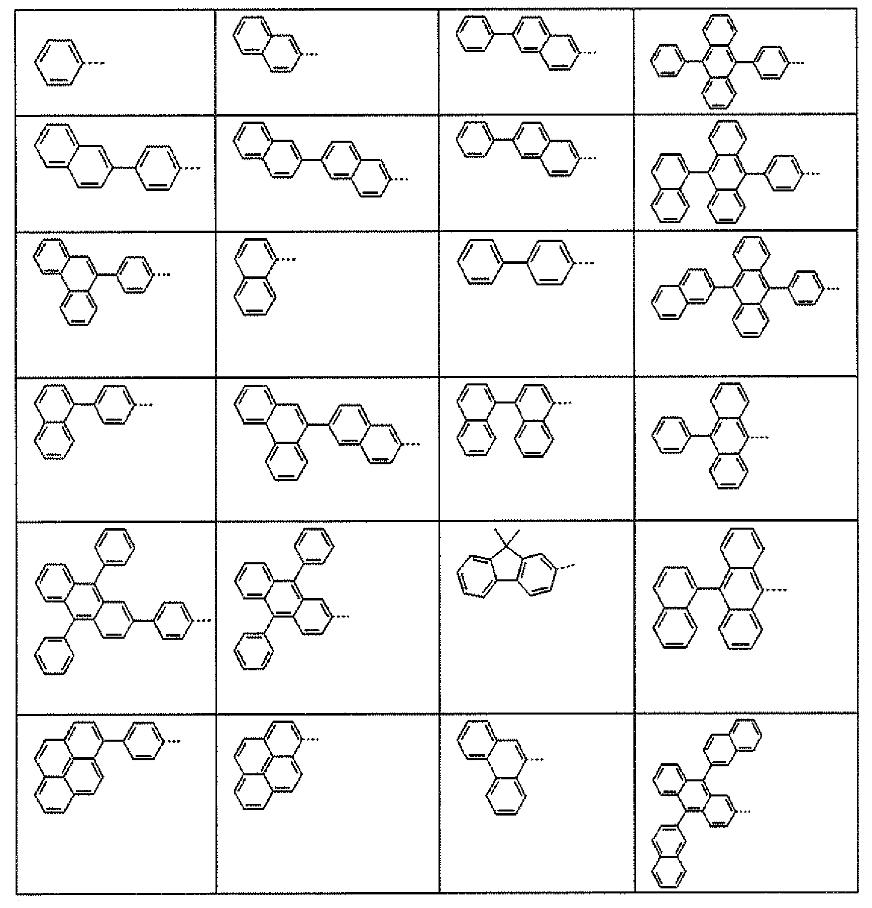
- In addition, the present invention provides a method for manufacturing the derivative that is represented by Formula 1.
- According to an embodiment of the present invention, in Formula 1, the manufacturing method of Formula 1 may be carried out in the same sequence as the following Reaction Equation 1, but is not limited thereto.

- In Reaction Equation 1, Ar1 to Ar5 are the same as those defined in Formula 1.
- According to Reaction Equation 1, pentagonal heteroaryl boronic acid is subjected to Suzuki coupling in conjunction with the alkyne compound to which the halogen group is introduced under the Pd catalyst. To the manufactured compound, the mixture in which ICl is dissolved in CH2Cl2 is dropped and agitated according to the manufacturing method that is described in the document [Journal of Organic Chemistry 2005, 70(9), 3511-3517], such that the compound A to which the iodo group is introduced is obtained in a solid form. By the manufacturing method that includes the method in which under the Pd catalyst, after the boronic acid or boron ester reactants are subjected to Suzuki Coupling and Ar2 is introduced, the bromo group is introduced by NBS or Br2, and while under the Pd catalyst, the Suzuki coupling and the bromination reaction are repeated, Ar3, Ar4 are sequentially introduced, the compound of Formula 1 according to the present invention may be manufactured.
- According to another embodiment of the present invention, in Reaction Equation 1, by using pentagonal 5-heteroaryl boronic acid in which the benzene ring is condensated instead of the pentagonal heteroaryl boronic acid, the compound of Formula 4 may be manufactured.
- As shown in Reaction Equations 1-1 to 1-4, Ar1 may be introduced from the substituted or unsubstituted acetylene group. In detail, in the case of Ar1, the phenyl group is intorduced from the substituted or unsubstituted phenylacetylene, and the naphthyl group may be introduced from the substituted or unsubstituted naphthylacetylene. In addition, from the substituted or unsubstituted phenanthrylacetylene, the phenanthryl group may be introduced, and from the substituted or unsubstituted pyridylacetylene, the pyridyl group may be introduced. Ar1 may be substituted by Ar1', Ar1' may introduce the other substituent groups by a general known reaction. The possible acetylene compound is shown in Table 2.
-

-

-

-

[Table 2] Reactant Reactant Reactant Reactant 


- In Table 2, p is an integer in the range of 0 to 5.
- In Reaction Equations 1-1 to 1-4 and Table 2,
- Ar1 is preferably substituted or unsubstituted phenyl group, substituted or unsubstituted naphthyl group, substituted or unsubstituted phenanthryl group, substituted or unsubstituted pyridyl group, and more preferably phenyl group.
- At this time, as the substituent group, as shown in Table 2, heavy hydrogen, halogen atoms such as fluorine, chlorine, and bromine, hydroxy group, nitrile group, nitro group, amino group, substituted amin group, alkoxy group such as methoxy group, alkyl group such as methyl group, ethyl group, tert-butyl group, and carbonyl group are preferable.
- In addition, at this time, as the substituent group, when the substituent group Ar1' introduced to the acetylene group is Br-, TfO-, since the substituent group such as aryl group, heteroaryl group, arylamin group is easily introduced under the Pd catalyst, as defined in Formula 1, Ar1 may be aryl group or heteroaryl group introduced as various substituent groups.
- In addition, at this time, as the substituent group, when the substituent group Ar1' which is introduced to the acetylene group is -CHO (formyl group), by a known reaction, since the heteroaryl group such as imidazole group, oxazole group, thiazole group including N,O or S may be manufactured, as defined in Formula 1, Ar1 may be the aryl group to which the heteroaryl group is introduced.
- In Formulas 1 to 4, Ar2 is preferably hydrogen, heavy hydrogen, iodo group, boronic acid, silyl group, and alkyl group. This is because Ar2 introduced by the iodo may introduce hydrogen, heavy hydrogen, silyl group, alkyl group by lithiation.
- In addition, Ar2 may be substituted by substituted or unsubstituted aryl group, substituted or unsubstituted heteroaryl group,or substituted or unsubstituted arylamin group and the like. These substituents may be introduced under the Pd catalyst through Suzuki coupling or arylamin coupling.
- The preferable aryl group is phenyl group, biphenyl group, terphenyl group, fluorene group, naphthyl group, phenanthryl, pyrenyl, anthracenyl group.
- The preferable heteroaryl group is carbazole group, triazine group, quinoline group, imidazole group, quinazoline group, thiophenyl group, imidazole group, oxazole group, thiazole group and the like.
- The preferable arylamino group is amino group that is substituted by aryl group, arylamino group that is substituted by aryl group, arylamino group that is substituted by heteroaryl group, and arylamino group that is substituted by alkylaryl group.
- Since Ar3 is introduced by using the same manufacturing method as Ar2, it is preferably hydrogen, heavy hydrogen, bromo group, boronic acid, silyl group, alkyl group, aryl group, heteroaryl group, arylamin group and the like.
- Since Ar4 is introduced by using the same manufacturing method as Ar2, it is preferably hydrogen, heavy hydrogen, bromo group, boronic acid, silyl group, alkyl group, aryl group, heteroaryl group, arylamin group and the like.
- In addition, the present invention provides an organic electronic device which includes a first electrode, a second electrode, and one or more organic material layers that are disposed between the first electrode and the second electrode, wherein one or more layers of the organic material layers include the compound that is represented by Formula 1.
- The organic electronic device according to the present invention may be manufactured by using a manufacturing method and a material of a general organic electronic device, except that one or more organic material layers are formed by using the above compounds.
- It is preferable that the organic material layer includes a hole injection layer or a hole transport layer, and the hole injection layer or hole transport layer includes the compound of Formula 1.
- In addition, the hole injection layer or hole transport layer may further include a dopant material.
- It is preferable that the organic material layer includes a light emitting layer, and the light emitting layer includes the compound of Formula 1.
- In addition, the light emitting layer may further include a fluorescent dopant material or phosphorescent dopant material.
- In addition, it is preferable that the organic material layer includes an electron injection layer or an electron transport layer, and the electron injection layer or electron transport layer includes the compound of Formula 1.
- In addition, the electron injection layer or electron transport layer may further include a dopant material.
- It is preferable that the organic electronic device may be selected from the group consisting of an organic light emitting device, an organic solar cell, an organic photoconductor (OPC) drum and an organic transistor, and the organic light emitting device is the most preferable example.
- Hereinafter, the organic light emitting device will be described.
- The compound of Formula 1 may be used as an organic material layer in the organic light emitting device because of pecularity of the structure.
- In an embodiment of the present invention, the organic light emitting device may have a structure that includes a first electrode, a second electrode, and an organic material layer that is disposed between them. The organic light emitting device may be manufactured by using a manufacturing method and a material of a general organic electronic device, except that the compound according to the present invention is used in one or more layers of the organic material layer of the organic light emitting device. The organic material layer of the organic light emitting device according to the present invention may have a single layer structure including one layer and a multilayered structure that includes two or more layers including a light emitting layer. In the case of when the organic material layer of the organic light emitting device according to the present invention has the multilayered structure, for example, this may be a structure in which hole injection layer, hole transport layer, light emitting layer, electron transport layer and the like are layered. However, the structure of the organic light emitting device is not limited to this, but may comprise a smaller number of organic material layers. In the organic material layer having a multilayered structure, the compound of Formula 1 may be included in a light emitting layer, a layer that performs simultaneously hole injection/hole transport and light emission, a layer that performs simultaneously hole transport and light emission, or a layer that performs simultaneously electron transport and light emission.
- For example, the structure of the organic light emitting device may have a structure shown in
FIGS. 1 to 4 , but is not limited thereto. -
FIG. 1 illustrates a structure of the organic light emitting device in which ananode 102, alight emitting layer 105 and acathode 107 are sequentially layered on asubstrate 101. In this structure, the compound of Formula 1 may be included in thelight emitting layer 105. -
FIG. 2 illustrates a structure of the organic light emitting device in which ananode 102, a hole injection/hole transport and light emittinglayer 105, anelectron transport layer 106 and acathode 107 are sequentially layered on asubstrate 101. In this structure, the compound of Formula 1 may be included in the hole injection/hole transport and light emittinglayer 105. -
FIG. 3 illustrates a structure of the organic light emitting device in which asubstrate 101, ananode 102, ahole injection layer 103, a hole transport and light emittinglayer 105, anelectron transport layer 106 and acathode 107 are sequentially layered. In this structure, the compound of Formula 1 may be included in the hole injection/hole transport and light emittinglayer 105. -
FIG. 4 illustrates a structure of the organic light emitting device in which asubstrate 101, ananode 102, ahole injection layer 103, ahole transport layer 104, an electron transport and light emittinglayer 105 and acathode 107 are sequentially layered. In this structure, the compound of Formula 1 may be included in the electron transport and light emittinglayer 105. - For example, the organic light emitting device according to the present invention may be manufactured by forming an anode by depositing metal or metal oxides having the conductivity or an alloy thereof on a substrate by using a PVD (physical vapor deposition) method such as sputtering or e-beam evaporation, forming the organic material layer that includes hole injection layer, hole transport layer, light emitting layer and electron transport layer thereon, and depositing the material that is capable of being used as a cathode thereon. In addition to this method, an organic light emitting device may be manufactured by sequentially depositing a cathode, an organic material layer, and an anode material on a substrate.
- The organic material layer may have a multilayered structure that includes a hole injection layer, a hole transport layer, a light emitting layer, and an electron transport layer, but is not limited thereto and may have a single layer structure. The organic material layer may be manufactured in a smaller number of layer by using various polymer materials and by using not a deposition method but a solvent process, for example, spin coating, dip coating, doctor blading, screen printing, inkjet printing, heat transferring method and the like.
- As the anode material, in general, it is preferable to use the material having the large work function so as to smoothly perform hole injection into the organic material layer. As examples of the anode material that is capable of being used in the present invention, there are metal or alloy thereof such as vanadium, chrome, copper, zinc, gold and the like; metal oxides such as zinc oxides, indium oxides, indium tin oxides (ITO), (indium zinc oxides (IZO) and the like; a combination of metal and oxides such as ZnO:Al or SnO2:Sb; conductive polymers such as poly(3-methyl compound), poly[3,4-(ethylene-1,2-dioxy) compound](PEDT), polypyrole and polyaniline, but it is not limited thereto.
- As the cathode material, in general, it is preferable to use the material having the small work function so as to smoothly perform electron injection into the organic material layer. As detailed examples of the cathode material, there are metal such as magnesium, calcium, sodium, potassium, titanium, indium, yttrium, lithium, gadolinium, aluminium, silver, tin, and lead or an alloy thereof; a multilayered structure material such as LiF/Al or LiO2/Al, but it is not limited thereto.
- The hole injection material is a material that is capable of well receiving holes from the anode at a low voltage, and it is preferable that the HOMO (highest occupied molecular orbital) of the hole injection material is a value between the work function of the anode material and the HOMO of the organic material layer around them. As detailed examples of the hole injection material, there are metal porphyrine, oligo compound, arylamine-based organic material, hexanitrilehexaazatriphenylene-based organic material, quinacridone-based organic material, perylene-based organic material, anthraquinone and polyaniline and poly compound-based conductive polymers, but it is not limited thereto.
- The hole transport material is a material that receives the holes from the anode or the hole injection layer and transfer them to the light emitting layer, and it is preferable to use the material having the large mobility to the holes. As detailed examples thereof, there are arylamine-based organic material, a conductive polymer, and a block copolymer in which a conjugate portion and a conjugate portion are simultaneously included, but it is not limited thereto.
- The light emitting material is a material that receives the holes and the electrons from the hole transport layer and the electron transport layer, combines them, such that light at a range of visible rays is emitted, and it is preferable to use the material having excellent photon efficiency to fluorescence or phosphorescence. As detailed examples thereof, there are a 8-hydroxy-quinoline aluminium complex (Alq3); a carbazole-based compound; a dimerized styryl compound; BAlq; 10-hydroxybenzoquinoline-metal compound; a benzoxazole, benzthiazole and benzimidazole-based compound; a poly(p-phenylenevinylene) (PPV)-based polymer; a spiro compound; polyfluorene, lubrene, anthracene, pyrene and the like, but it is not limited thereto.
- The electron transport material is a material that receives the electrons from the cathode and transfer them to the light emitting layer, and it is preferable to use the material having the large mobility to the electrons. As detailed examples thereof, there are a 8-hydroxyquinoline Al complex; a complex including Alq3; an organic radical compound; a hydroxyflavone-metal complex; oxazole, thiazole and imidazole-based compound and condensated ring compound thereof; quinoline and quinoline condensated ring compound; phenanthroline and phenanthroline condensated rinig compound; quinazoline and quinazoline condensated ring compound and the like, but it is not limited thereto.
- The organic light emitting device according to the present invention may be a front side light emitting type, a rear side light emitting type, or a both sides light emitting type according to the used material.
- The compound according to the present invention may be operated in a principle that is similar to a principle applied to the organic light emitting device in organic solar cell, organic photoconductor, organic transistor, and organic electronic device.
- Hereinafter, preferable Preparation Examples will be described in order to help understanding of the present invention. However, the following Preparation Examples are set forth to illustrate the present invention, but the scope of the present invention is not limited thereto.
- The compound of Formula 1 according to the present invention can be manufactured with multistage chemical reactions. The above compounds may be manufactured by using the methods described in the following Preparation Examples. As described in the following Synthesis Examples, the compounds of Formula 1 may be manufactured from the following intermediate compounds. In the intermediate compounds, Br may be substituted by any other reactive atom or functional group.
- Table 1 shows reactants that were used in the manufacturing of Formula 1, and the reactants were synthesized by using a general or known method, or used by purchasing commercial product.
[TABLE 1] No. Reactant No. Reactant S-1 
S-2 
S-3 
S-4 
S-5 
S-6 
S-7 
S-8 
S-9 
S-10 
S-11 
S-12 
S-13 
S-14 
S-15 
S-16 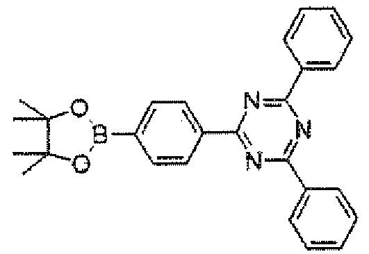
S-17 
S-18 
S-19 
S-20 
S-21 
S-22 
S-23 
S-24 
S-25 
S-26 
S-27 
S-28 
S-29 
S-30 
S-31 
S-32 
S-33 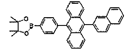
S-34 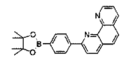
S-35 
S-36 
S-37 
S-38 
S-39 
S-40 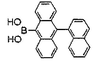
S-41 
S-42 
S-43 
S-44 
-

- 1-bromo-2-(2-phenylethynyl)-benzene (16.3 g, 63.5 mmol), thiophen-3-yl-3-boronic acid (9.75 g, 76.2 mmol), and sodium carbonate (21.1 g, 152.4 mmol) were suspended in the mixture of toluene (200 mL), ethanol (1.00 mL) and water (100 mL). To the suspension solution, tetrakis(triphenylphosphine)palladium (2.1 g, 1.83 mmol) was applied. The mixture was refluxed and agitated for about 24 hours, and the refluxed mixture was cooled to room temperature. The organic material layer was separated, wahsed with water, and the aqueous layer was extracted with chloroform. The organic extract was dried on magnesium sulfate and concentrated under the vacuum to synthesize the compound A-1-1 (16.7 g, yield 84%).
MS [M+H]+ = 261 - After the compound A-1-1 (6.2 g, 23.8 mmol) was dissolved in CHCl3 (100 mL), ICl (3.87 g, 23.8 mmol) was dissolved in
CHCl 3 10 mL, slowly dropped, and agitated for 12 hours. The formed yellow solid was filtered, washed with hexane, and dried to synthesize the compound A-1 (3 g, yield 32%).
MS [M]+ = 386 -

- 1-bromo-2-(2-phenylethynyl}-benzene (15.4 g, 60.0 mmol), furan-3-yl-3-boronic acid (4.8 g, 58.0 mmol), and sodium carbonate (17.6 g, 152.4 mmol) were suspended in the mixture of toluene (200 mL), ethanol (100 mL) and water (100 mL). To the suspension solution, tetrakis(triphenylphosphine)palladium (2.0 g, 2.00 mmol) was applied. The mixture was refluxed and agitated for about 24 hours, and the refluxed mixture was cooled to room temperature. The organic material layer was separated, wahsed with water, and the aqueous layer was extracted with chloroform. The organic extract was dried on magnesium sulfate and concentrated under the vacuum to synthesize the compound A-2-1 (14.4 g, yield 67%).
MS [M+H]+= 245 - After the compound A-1-2 (14.4 g, 58.9 mmol) was dissolved in CHCl3 (120 mL), ICl (9.58 g, 58.9 mmol) was dissolved in CHCl3 15 mL, slowly dropped, and agitated for 12 hours. The formed yellow solid was filtered, washed with hexane, and dried to synthesize the compound A-2 (10.5 g, yield 48%).
MS [M]+= 370 -

- In the synthesis of the compound A-1-1, the compound A-3-1 (13.2 g, yield 56%) was synthesized by using the same method as the compound A-1-1, except that benzo[b]thiophen-3-yl-3-boronic acid (13.6 g, 76.2 mmol) was used instead of thiophene-3-boronic acid, and 1-bromo-2-(2-phenylethynyl)-benzene (19.6 g, 76.2 mmol), and sodium carbonate (21.1 g, 153 mmol) were used.
MS[M+H]+=311 - After the compound A-3-1 (11 g, 35.6 mmol) was dissolved in CHCl3 (100 mL), ICl (5.79 g, 23.8 mmol) was dissolved in
CHCl 3 10 mL, slowly dropped, and agitated for 12 hours. The fonned yellow solid was filtered, washed with hexane, and dried to synthesize the compound A-3 (11.2 g, yield 72%).
MS [M]+=436 -

- In the synthesis of the compound A-1-1, the compound A-4-1 (9.1 g, yield 62%) was synthesized by using the same method as the compound A-1-1, except that benzofuran-3-yl-3-boronic acid (8.1 g, 50.0 mmol) was used instead of thiophene-3-boronic acid, and 1-bromo-2-(2-phenylethynyl)-benzene (13.4 g, 52.0 mmol), and sodium carbonate (15.8 g, 153 mmol) were used.
MS [M+H]+= 295 - After the compound A-4-1 (9.1 g, 30.9 mmol) was dissolved in CHCl3 (80 mL), ICl (5.4 g, 33.0 mmol) was dissolved in
CHCl 3 20 mL, slowly dropped, and agitated for 12 hours. The formed yellow solid was filtered, washed with hexane, and dried to synthesize the compound A-4 (8.3 g, yield 64%).
MS [M]+= 420 - The compound A-1, and 1 to 1.5 equivalents of the substituted or unsubstituted arylboronic acid (or arylboron ester) or the substituted or unsubstituted heteroarylboronic acid (or arylboron ester) like the reactant S-No. described in Table 1-I were put, dissolved in THF, 0.02 equivalents of Pd(PPh3) and 2 equivalents or more of 2M K2CO3/H2O aqueous solution were added, and heated and agitated for 3 to 16 hours. The reaction mixture was cooled to normal temperature, filtered or extracted with the organic solvent, separated, purified, and dried to synthesize the 1B-1-No compound, and the results thereof are described in Table 1-1-1.

[Table 1-1-1] Syn. Ex. 1-1-No Product 1B-1-No Reactant Ar2 MS [M+H]+ 1-1-1 compound 1B-1-1 S-1 
387 1-1-2 compound 1B-1-2 S-3 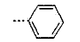
337 1-1-3 compound 1B-1-3 S-5 
639 1-1-4 compound 1B-1-4 S-8 
589 1-1-5 compound 1B-1-5 S-13 
370 1-1-6 compound 1B-1-6 S-14 
446 1-1-7 compound 1B-1-7 S-10 
589 1-1-8 compound 1B-1-8 S-9 
689 - Naphthalen-2-yl-2-boronic acid (1.6 g, 9.3 mmol) that was the reactant S-1 of Table 1, the compound A-1 (3 g, 7.8 mmol), and sodium carbonate (2.4 g, 15.5 mmol) were suspended in the mixture of toluene (100 mL), ethanol (10 mL) and water (20 mL).
- To the suspension solution, tetrakis(triphenylphosphine)palladium (0.2 g, 1.6 mmol) was applied. The mixture was refluxed and agitated for about 24 hours, and the refluxed mixture was cooled to room temperature. The organic material layer was separated, wahsed with water, and the aqueous layer was extracted with chloroform. The organic extract was dried on magnesium sulfate and concentrated under the vacuum to synthesize the compound 1B-1-1 (2.3 g, yield 77%).
MS [M+H]+= 387 - In Synthesis Example 1-1-1, it was synthesized by using the same method to synthesize the compound 1B-1-2, except that phenylboronic acid S-3 was used instead of naphthalene-2-yl-2-boronic acid.
MS: [M+H]+=337 - In Synthesis Example 1-1-1, it was synthesized by using the same method to synthesize the compounds 1B-1-3, 1B-1-4, 1B-1-5, 1B-1-6, 1B-1-7, and 1B-1-8, except that the reactants S-5, S-8, S-13, S-14, S-10, and S-9 were used instead of naphthalene-2-yl-2-boronic acid.
- The compound 1B-1-No was dissolved in chloroform, and 1 equivalent of N-bromo succinimide was added thereto, and agitated for 3 to 8 hours at normal temperature. Distilled water was put into the reaction solution, the termination of the reaction was carried out, and the organic material layer was extracted. The reaction solution was concentrated, and recrystalized with EtOH to synthesize the compound 1C-1-No, and the results are described in Table 1-2-1.

[Table 1-2-1] Syn. Ex. 1-2-No Product 1C-1-No Reactant 1B-1-No Ar2 MS [M]+ 1-2-1 compound 1C-1-1 compound 1B -1-1 
465 1-2-2 compound 1C-1-2 compound 1B-1-2 
415 1-2-3 compound C-1-3 compound 1B-1-3 
717 1-2-4 compound 1C-1-4 compound 1B-1-4 
667 1-2-5 compound 1C-1-5 compound 1B-1-5 
449 1-2-6 compound 1C-1-6 compound 1B-1-6 
525 1-2-7 compound 1C-1-7 compound 1B-1-7 
667 1-2-8 compound 1C-1-8 compounds 1B-1-8 
767 - Alter the compound 1B-1-1 (2.3 g, 6.0 mmol) was dissolved in
DMF 20 mL, NBS (1.1 g, 6.0 mmol) was applied thereto and agitated at normal temperature for 2 hours. Afterwater 50 mL was applied thereto to precipitate the solid, it was filtered, washed with ethanol, and dried to synthesize the compound 1C-1-1 (2.1 g, yield 85%).
MS [M]+= 465 - In Synthesis Example 1-2-1, it was synthesized by using the same method to synthesize the compound 1C-1-2, except that the compound 1B-1-2 was used instead of the compound 1B-1-1.
MS: [M]+ = 415 - In Synthesis Example 1-2-1, it was synthesized by using the same method to synthesize the compounds 1C-1-3, 1C-1-4, 1C-1-5, 1C-1-6, 1C-1-7, 1C-1-8, except that the compounds 1B-1-3, 1B-1-4, 1B-1-5, 1B-1-6, 1B-1-7, and 1B-1-8 were used instead of the compound 1B-1-1.
- The compound 1C-1-No, and 1 to 1.5 equivalents of the substituted or unsubstituted arylboronic acid (or arylboron ester) or the substituted or unsubstituted heteroarylboronic acid (or arylboron ester) like the reactant S-No. described in Table 1-1 were put, dissolved in THF, 0.02 equivalents of Pd(PPh3) and 2 equivalents or more of 2M K2CO3/H2O aqueous solution were added, and heated and agitated for 3 to 16 hours. The reaction mixture was cooled to normal temperature, filtered or extracted with the organic solvent, separated, purified, and dried to synthesize the 1D-1-5-No compound.
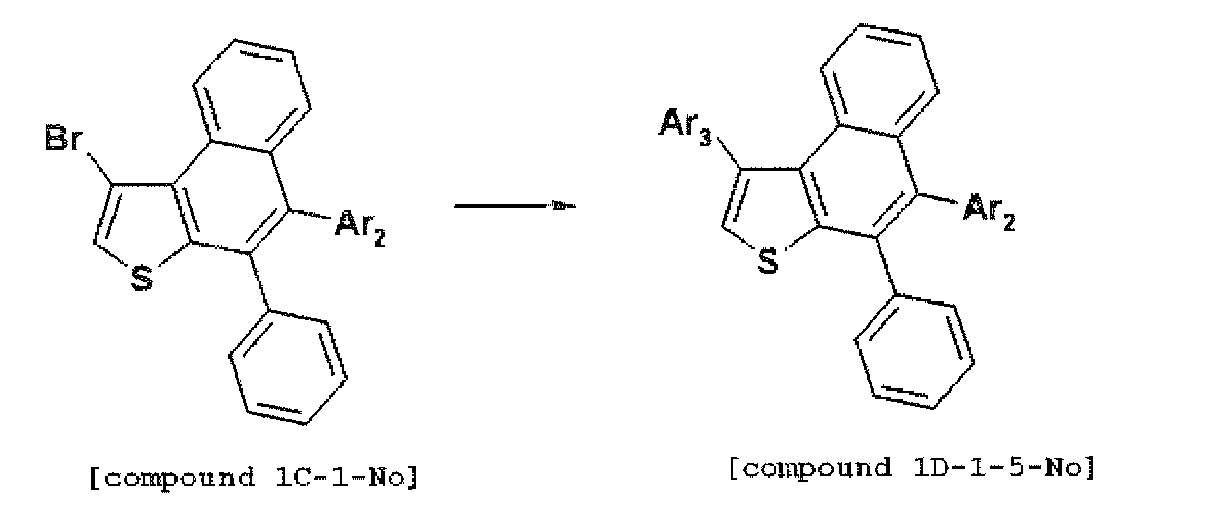
-

- Phenyl boronic acid (1 g, 8.2 mmol), the compound 1C-1-1 (2.1 g, 5.1 mmol), and sodium carbonate (1.4 g, 10.2 mmol) were suspended in the mixture of toluene (50 mL), ethanol (10 mL) and water (20 mL). To the suspension solution, tetrakis(triphenylphosphine)palladium (0.12 g, 1.0 mmol) was applied. The mixture was refluxed and agitated for about 1 hours, and the refluxed mixture was cooled to room temperature. The organic material layer was separated, wahsed with water, and the aqueous layer was extracted with chloroform. The organic extract was dried on magnesium sulfate and concentrated under the vacuum to synthesize the compound 1D-1-1 (1.8 g, yield 77%).
- In Synthesis Example 1-3-1, it was synthesized by using the same method to synthesize the compound 1D-1-2, except that the reactant S-1 was used instead of the phenyl boronic acid reactant S-3.
- In Synthesis Example 1-3-1, it was synthesized by using the same method to synthesize the compound 1D-1-3, except that the reactant S-11 was used instead of the phenyl boronic acid reactant S-3.
- In Synthesis Example 1-3-1, it was synthesized by using the same method to synthesize the compounds 1D-1-4, 1D-1-5, 1D-1-6, 1D-1-7, and 1D-1-8, except that the reactants S-20, S-12, S-8, S-10, and S-4 were used instead of the phenyl boronic acid reactant S-3.
[Table 1-3-1] Syn. Ex. 1-3-No Product 1D-1-No Ar3 Ar2 MS [M+H]+ 1-3-1 compound 1D-1-1 

463 1-3-2 compounds 1D-1-2 

513 1-3-3 compound 1D-1-3 

539 1-3-4 compound 1D-1-4 

621 1-3-5 compound 1D-1-5 

544 1-3-6 compound 1D-1-6 

715 1-3-7 compound 1D-1-7 

715 1-3-8 compound 1D-1-8 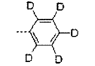

468 -

- Phenyl boronic acid S-3 (2.2 g, 18.0 mmol), the compound 1C-1-2 (7.45 g, 16.0 mmol), and sodium carbonate (4.98 g, 36.0 mmol) were suspended in the mixture of toluene (150 mL), ethanol (20 mL) and water (40 mL). To the suspension solution, tetrakis(triphenylphosphine)palladium (0.24 g, 2.00 mmol) was applied. The mixture was refluxed and agitated for about 15 hours, and the refluxed mixture was cooled to room temperature. The organic material layer was separated, wahsed with water, and the aqueous layer was extracted with chloroform. The organic extract was dried on magnesium sulfate and concentrated under the vacuum to synthesize the compound 1D-2-1 (6.7 g, yield 90%).
- In Synthesis Example 1-4-1. it was synthesized by using the same method to synthesize the compounds 1D-2-2 to 1D-2-11, except that the reactants S-1, S-11, S-20, S-12, S-8, S-10, S-4, S-19, S-15, and S-17 were used instead of the phenyl boronic acid reactant S-3.
- The results are described in Table 1-4-1.
[TABLE 1-4-1] Syn. Ex. 1-4-No. Product 1D-2-No Ar3 Ar2 MS [M+H]+ 1-4-1 compound 1D-2-1 

413 1-4-2 compound 1D-2-2 

463 1-4-3 compound 1D-2-3 

489 1-4-4 compound 1D-2-4 

571 1-4-5 compound 1D-2-5 

494 1-4-6 compound 1D-2-6 

665 1-4-7 compound 1D-2-7 

665 1-4-8 compound 1D-2-8 

413 1-4-9 compound 1D-2-9 

529 1-4-10 compound 1D-2-10 

605 1-4-11 compound 1D-2-11 

707 -

- Phenyl boronic acid S-3 (2.2 g, 18.0 mmol), the compound 1C-1-7 (10.68 g, 16.0 mmol), and sodium carbonate (4.98 g, 36.0 mmol) were suspended in the mixture of toluene (150 mL), ethanol (20 mL) and water (40 mL). To the suspension solution, tetrakis(triphenylphosphine)palladium (0.24 g, 2.0 mmol) was applied. The mixture was refluxed and agitated for about 15 hours, and the refluxed mixture was cooled to room temperature. The formed solid was filtered and washed with water and ethanol. It was dried in the oven under the vacuum to synthesize the compound 1D-3-1 (9.26 g, yield 87%).
- In Synthesis Example 1-5-1, it was synthesized by using the same method to synthesize the compound 1D-3-2, except that the reactant S-1 was used instead of the reactant S-3.
- In Synthesis Example 1-5-1, it was synthesized by using the same method to synthesize the compounds 1D-3-3 to 1D-3-13, except that the reactants S-11, S-12, and S-4 were used instead of the phenyl boronic acid reactant S-3.
[TABLE 1-5-1] Syn. Ex. 1-5-No. Product 1D-3-No Ar3 Ar2 MS [M+H]+ 1-5-1 compound 1D-3-1 

665 1-5-2 compounds 1D-3-2 
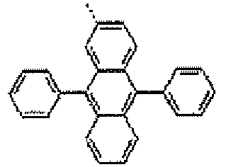
715 1-5-3 compound 1D-3-3 
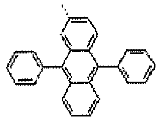
741 1-5-4 compound 1D-3-4 

746 1-5-5 compounds 1D-3-5 

670 -

- Phenyl boronic acid S-3 (2.2 g, 18.0 mmol), the compound 1C-1-3 (10.68 g, 16.0 mmol), and sodium carbonate (4.98 g, 36.0 mmol) were suspended in the mixture of toluene (150 mL), ethanol (20 mL) and water (40 mL). To the suspension solution, tetrakis(triphenylphosphine)palladium (0.24 g, 2.0 mmol) was applied. The mixture was refluxed and agitated for about 15 hours, and the refluxed mixture was cooled to room temperature. The formed solid was filtered and washed with water and ethanol. It was dried in the oven under the vacuum to synthesize the compound 1D-4-1 (9.26 g, yield 87%).
- In Synthesis Example 1-6-1, it was synthesized by using the same method to synthesize the compound 1D-4-2, except that the reactant S-1 was used instead of the phenyl boronic acid reactant S-3.
[TABLE 1-6-1] Syn. Ex. 1-6-No Product 1D-4-No Ar3 Ar2 MS [M+H]+ 1-6-1 compound 1D-4-1 

714 1-6-2 compound 1D-4-9 
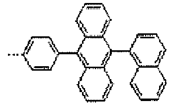
764 -

- Phenyl moronic acid S-3 (2.44 g, 20.0 mmol), the compound 1C-1-5 (8.1 g, 18.0 mmol), and sodium carbonate (4.98 g, 36.0 mmol) were suspended in the mixture of toluene (150 mL), ethanol (20 mL) and water (40 mL). To the suspension solution, tetrakis(triphenylphosphine)palladium (0.24 g, 2.0 mmol) was applied. The mixture was refluxed and agitated for about 15 hours, and the refluxed mixture was cooled to room temperature. The formed solid was filtered and washed with water and ethanol. It was dried in the oven under the vacuum to synthesize the compound 1D-5-1 (7.08 g, yield 88%).
- In Synthesis Example 1-7-1, it was synthesized by using the same method to synthesize the compounds 1D-5-2 to 1D-5-3, except that the reactants S-1, and S-11 were used instead of the phenyl boronic acid reactant S-3.
- In Synthesis Example 1-7-4, it was synthesized by using the same method to synthesize the compound 1D-5-4, except that the reactant S-11 was used instead of the phenyl boronic acid reactant S-3 and the compound 1C-1-6 was used instead of the compound 1C-1-5.
[TABLE 1-7-1] Syn. Ex. 1-7-No Product 1D-5-No Ar3 Ar2 MS [M+H]+ 1-7-1 compound 1D-5-1 

447 1-7-2 compound 1D-5-2 

496 1-7-3 compound 1D-5-3 

522 1-7-4 compound 1D-5-4 

599 - The compounds 1D-1-No to 1D-5-No were dissolved in chloroform, and 1 equivalent of N-bromo succinimide was added thereto, and agitated for 3 to 6 hours at normal temperature. The solid was formed by applying distilled water to the reaction solution, filtered and dried, and recrystallized with CHCl3/EtOH to synthesize the compounds 1E-1-No. 1E-2-No, 1E-3-No, and 1E-4-No.

-

- After the compound 1D-1-1 (4.6g, 10.0 mmol)) was dissolved in
DMF 40 mL, NBS (1.8 g, 10.0 mmol) was applied thereto and agitated at normal temperature for 3 hours. Afterwater 100 mL was applied thereto to precipitate the solid, it is filtered, washed with ethanol, and dried to synthesize the compound 1E-1-1 (4.98 g, yield 92%). - The compound was manufactured by using the same method as Synthesis Example 1-8-1, except that the corresponding compounds 1D-1-No to 1D-5-No were used instead of the compound 1D-1-1. The results are described in the following Tables 1-8-1 to 1-11-1.
[TABLE 1-8-1] Syn. Ex. 1-8-No Product 1E-1-No Ar3 Ar2 MS [M]+ 1-8-1 compound 1E-1-1 

541 1-8-2 compound 1E-1-2 

591 1-8-3 compound 1E-1-3 
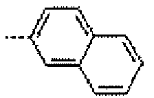
617 1-8-4 compound 1E-1-4 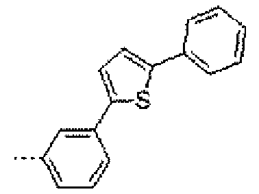
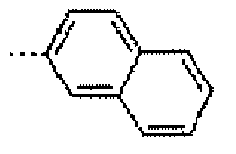
699 1-8-5 compound 1E-1-5 

622 1-8-6 compound 1E-1-6 

793 1-8-7 compound 1E-1-7 

793 1-8-8 compound 1E-1-8 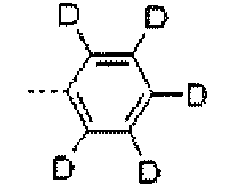
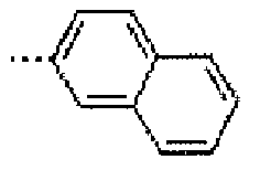
546 [TABLE 1-9-1] Syn. Ex. 1-9-No Product. 1E-2-No Ar3 Ar2 MS [M]+ 1-9-1 compound 1E-2-1 

491 1-9-2 compound 1E-2-2 

541 1-9-3 compound 1E-2-3 

567 1-9-4 compound 1E-2-4 

649 1-9-5 compound 1E-2-5 

572 1-9-6 compound 1E-2-6 

743 1-9-7 compound 1E-2-7 

743 1-9-8 compound 1E-2-8 

496 1-9-9 compound 1E-2-9 

607 1-9-10 compound 1E-2-10 

683 1-9-11 compound 1E-2-11 

785 [TABLE 1-10-1] Syn. Ex. 1-10-No Product 1E-3-No Ar3 Ar2 MS [M]+ 1-10-1 compound 1E-3-1 

793 1-10-2 compound 1E-3-2 

843 1-10-3 compound 1E-3-3 

743 1-10-4 compound 1E-3-4 

743 1-10-5 compound 1E-3-5 

843 1-10-6 compound 1E-3-6 

819 1-10-7 compound E-3-7 

793 1-10-8 compound E-3-8 

824 1-10-9 compound 1E-3-9 

793 [TABLE 1-11-1] Syn. Ex. 1-11-No Product 1E-4-No Ar3 Ar2 MS [M]+ 1-11-1 compound 1E-4-1 

525 1-11-2 compound 1E-4-2 

601 1-11-3 compound 1E-4-3 

601 1-11-4 compound 1E-4-4 
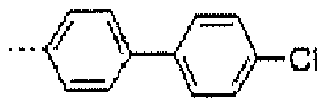
677 1-11-5 compound 1E-4-5 

575 - The compound A-2, and 1 to 1.5 equivalents of the substituted or unsubstituted arylboronic acid (or arylboron ester) or the substituted or unsubstituted heteroarylboronic acid (or arylboron ester) like the reactant S-No. described in Table 1 were put, dissolved in THF, 0.02 equivalents of Pd(PPh3) and 2 equivalents or more of 2M K2CO3/H2O aqueous solution were added, and heated and agitated for 3 to 16 hours. The reaction mixture was cooled to formal temperature, filtered or extracted with the organic solvent, separated, purified, and dried to synthesize the 2B-1-No compound, and the results thereof are described in Table 2-1-1.

- In Synthesis Example 1-1-1, the compound 2B-1-1 was synthesized by using the same method, except that naphthalen-2-yl-2-boronic acid that was the reactant S-1 or Table 1 and the compound A-2 were used.
- In Synthesis Example 2-1-1, it was synthesized by using the same method to synthesize the compounds 2B-1-2, 2B-1-3, 2B-1-4, 2B-1-5, and 2B-1-6, except that the reactants S-3, S-5, S-8, S-10, and S-9 were used instead of naphthalene-2-yl-2-boronic acid.
[TABLE 2-1-1] Syn. Ex. 2-1-No Product 2B-1-No reactant Ar2 MS [M+H]+ 2-1-1 compound 2B-1-1 S-1 
371 2-1-2 compound 2B-1-2 S-3 
321 2-1-3 compound 2B-1-3 S-5 
623 2-1-4 compound 2B-1-4 S-8 
573 2-1-5 compound 2B-1-5 S-10 
572 2-1-6 compound 2B-1-6 S-9 
673 - The compound 2B-1-No was dissolved in chloroform, and 1 equivalent of N-bromo succinimide was added thereto, and agitated for 3 to 8 hours at normal temperature. Distilled water was put into the reaction solution, the termination of the reaction was carried out, and the organic material layer was extracted. The reaction solution was concentrated, and recrystalized with EtOH to synthesize the compound 2C-1-No, and the results are described in Table 2-2-1.

- In Synthesis Example 1-2-1, it was synthesized by using the same method to synthesize the compound 2C-1-1, except that the compound 2B-1-1 ways used instead of the compound 1B-1-1.
- In Synthesis Example 2-2-1, it was synthesized by using the same method to synthesize the compounds 2C-1-2, 2C-1-3, 2C-1-4, 2C-1-5, and 2C-1-6, except that the compounds 2B-1-2, 2B-1-3, 2B-1-4 2B-1-5, and 2B-1-6 were used instead of the compound 2B-1-1.
- The results are described in Table 2-2-1.
[TABLE 2-2-1] Syn. Ex. 2-2-No Product 2C-1-No reactant 23-1-No Ar2 MS [M]+ 2-2-1 compound 2C-1-1 compound 2B-1-1 
449 2-2-2 compound 2C-1-2 compound 23-1-2 
399 2-2-3 compounds 2C-1-3 compound 2B-1-3 
701 2-2-4 compounds 2C-1-4 compound 2B-1-4 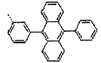
651 2-2-5 compound 2C-1-5 compound 23-1-5 
651 2-2-6 compound 2C-1-6 compound 23-1-6 
751 - The compound 2C-1-No, and 1 to 1.5 equivalents of the substituted or unsubstituted arylboronic acid (or arylboron ester) or the substituted or unsubstituted heteroarylboronic acid (or arylboron ester) like the reactant S-No. described in Table 1 were put, dissolved in THF, 0.02 equivalents of Pd(PPh3) and 2 equivalents or more of 2M K2CO3/H2O aqueous solution were added, and heated and agitated for 3 to 16 hours. The reaction mixture was cooled to normal temperature, filtered or extracted with the organic solvent, separated, purified, and dried to synthesize the 2D-1-No compound.

- In Synthesis Example 1-3-1, it was synthesized by using the same method to synthesize the compound 2D-1-1, except that the phenyl boronic acid reactant S-3 and the compound 2C-1-1 were used instead of the compound 1C-1-1.
- In Synthesis Example 2-3-1, it was synthesized by using the same method to synthesize the compound 2D-1-2, except that the reactant S-1 was used instead of the phenyl boronic acid reactant S-3.
- In Synthesis Example 2-3-1, it was synthesized by using the same method to synthesize the compound 2D-1-3, except that the reactant S-1 was used instead of the phenyl boronic acid reactant S-3 and the compound 2C-1-2 was used instead of the compound 2C-1-1.
- In Synthesis Example 2-3-1, it was synthesized by using the same method to synthesize the compound 2D-1-4, except that the compound 2C-1-3 was used instead of the compound 2C-1-1.
- In Synthesis Example 2-3-1, it was synthesized by using the same method to synthesize the compound 2D-1-5, except that the reactant S-11 was used instead of the phenyl boronic acid reactant S-3 and the compound 2C-1-4 was used instead of the compound 2C-1-1.
- In Synthesis Example 2-3-1, it was synthesized by using the same method to synthesize the compound 2D-1-6, except that the reactant S-4 was used instead of the phenyl boronic acid reactant S-3 and the compound 2C-1-5 was used instead of the compound 2C-1-1.
- In Synthesis Example 2-3-1, it was synthesized by using the same method to synthesize the compound 2D-1-7, except that the compound 2C-1-6 was used instead of the compound 2C-1-1.
- The results are described in Table 2-3-1.
[TABLE 2-3-1] Syn. Ex. 2-3-No Product 2D-1-No Ar3 Ar2 MS [M+H]+ 2-3-1 compound 2D-1-1 
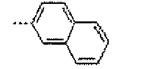
447 2-3-2 compound 2D-1-2 

497 2-3-3 compound 2D-1-3 

447 2-3-4 compound 2D-1-4 
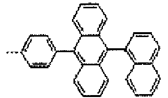
699 2-3-5 compound 2D-1-5 

725 2-3-6 compound 2D-1-6 

654 2-3-7 compound 2D-1-7 

749 - In Synthesis Example 1-4-1, it was synthesized by using the same method to synthesize the compounds 2E-1-1 to 2E-1-7, except that the compounds 2D-1-1 to 2D-1-7 were used instead of the compound 1-4-1.
[TABLE 2-4-1] Syn. Ex. 2-4-No Product 2E-1-No Ar3 Ar2 MS [M]+ 2-4-1 compound 2E-1-1 

525 2-4-2 compound 2E-1-2 

575 2-4-3 compound 2E-1-3 

525 2-4-4 compound 2E-1-4 
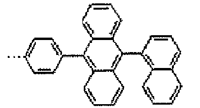
696 2-4-5 compound 2E-1-5 

724 2-4-6 compound 2E-1-6 

653 2-4-7 compound 2E-1-7 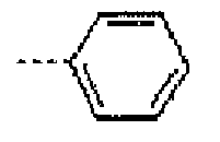

748 -

[TABLE 3-1-1] Syn. Ex. 3-1-No Product 1F-1-No MS [M+H]+ 3-1-1 compound 1F-1-1 
457 3-1-2 compound 1F-1-2 
507 3-1-3 compounds 1F-1-3 
491 - To the compound 1E-2-1 (20.3 g, 41.3 mmol) solution that was manufactured in Synthesis Example 1-9-1 in anhydrous THF (50 mL), n-BuLi (61.9 mmol), 24.8 mL in 2.5 M hexane solution) was dropped under the nitrogen atmosphere at -78°C. After the mixture was agitated for about 1 hour, trimethyl borate (14 mL, 123.9 mmol) was dropped at -78°C. After about 30 min, the cooling vessel was removed, and the mixture was agitated at room temperature for about 3 hours. 1N HCl (200 mL) was added to the above mixture, and extracted with ethyl acetate. The organic material layer was dried on magnesium sulfate and concentrated under the vacuum. The crude product was agitated with petroleum ether and precipitated, filtered, and dried to synthesize the compound 1F-1-1 (11.9 g, yield 63%).
- In Synthesis Example 3-1-1, is was synthesized by using the same method to synthesize the compound 1F-1-2, except that the compound 1E-1-1 was used instead of the compound 1E-2-1.
- In Synthesis Example 3-1-1, it was synthesized by using the same method to synthesize the compound 1F-1-3, except that the compound 2E-1-1 was used instead of the compound 1E-2-1.
-

- The compound 1E-1-No, and 1 to 1.5 equivalents of the substituted or unsubstituted arylboronic acid (or arylboron ester) or the substituted or unsubstituted heteroarylboronic acid (or arylboron ester) were put, dissolved in THF, 0.02 equivalents of Pd(PPh3) and 2 equivalents or more of 2M K2CO3/H2O aqueous solution were added, and heated and agitated for 3 to 16 hours. The reaction mixture was cooled to normal temperature, filtered or extracted with the organic solvent, separated, purified, and dried to prepare the following 1-1-No compound, and the results thereof are described in Table 1-1.
-

- 2-[9,10-diphenyl-2-anthracenyl]-4,4,5,5-tetramethyl-1,3,2-dioxaborolane (2.2 g, 4,9 mmol) that was the reactant S-10, the compound 1E-1-1 (2.2 g, 4.1 mmol) that was prepared in Synthesis Example 1-8-1, and sodium carbonate (1.4 g, 10.0 mmol) were suspended in the mixture of tetrahydrofurane (100 mL) and water (50 mL). Tetrakis(triphenylphosphine)palladium (0.1 g, 0.1 mmol) was applied to the suspension solution. The mixture was refluxed and agitated for about 24 hours, and the refluxed mixture was cooled to room temperature. The prepared solid was purified with filtered THF/EtOH to prepare the compound 1-1-7 (2.5 g, yield 76%).
- In Synthesis Example 1-1-7. it was synthesized by using the same method to prepare the compounds 1-1-1, 1-1-2, 1-1-3, 1-1-4, 1-1-5, and 1-1-6, except that the reactants S-1, S-11, S-20, S-12, S-8, S-10 were used instead of the reactant S-3.
- In Synthesis Example 1-1-7, it was synthesized by using the same method to prepare the compounds 1-1-8, 1-1-9, 1-1-10, 1-1-11, 1-1-12, 1-1-13, and 1-1-14, except that the reactants S-4, S-19, S-15, S-17, S-21, S-18, and S-16 were used instead of the reactant S-3.
- In Preparation Examples 1-1-1 to 1-1-6 and Preparation Examples 1-1-8 tol-1-14, they were prepared by using the same method as Preparation Example 1-1-7 by using the compound 1E-1-1 and boronic acid or boron ester compounds in the reactants of Table 1.
[TABLE 1-1] Prep. Ex. 1-1-No Product 1-1-No structure MS [M+H] + 1-1-1 compound 1-1-1 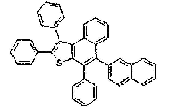
539 1-1-2 compound 1-1-2 
589 1-1-3 compound 1-1-3 
615 1-1-4 compound 1-1-4 
697 1-1-5 compound 1-1-5 
620 1-1-6 compound 1-1-6 
791 1-1-7 compound 1-1-7 
791 1-1-8 compound 1-1-8 
544 1-1-9 compound 1-1-9 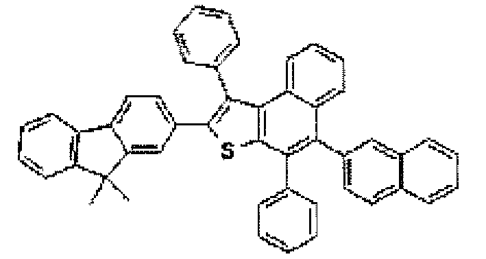
655 1-1-10 compound 1-1-10 
731 1-1-11 compound 1-1-11 
833 1-1-12 compound 1-1-12 
621 1-1-13 compound 1-1-13 
704 1-1-14 compound 1-1-14 
770 -

- [4-(9H-carbazol]-9-yl)phenyl boronic acid (1.4 g, 4.9 mmol), the compound E-2 (2.0 g, 4.1 mmol) that was prepared in Preparation Example 2, and sodium carbonate (1.4 g, 10.0 mmol) were suspended in the mixture of tetrahydrofurane (100 mL) and water (50 mL). Tetrakis(triphenylphosphine)palladium (0.1 g, 0.1 mmol) was applied to the suspension solution. The mixture was refluxed and agitated for about 24 hours, and the refluxed mixture was cooled to room temperature. The prepared solid was purified with filtered THF/EtOH to prepare the compound 1-2-4 (1.6 g, yield 58%).
- In Preparation Examples 1-2-1 to 1-2-3, Preparation Examples 1-2-5 to 1-2-7, Preparation Examples 1-2-11, 1-2-13, 1-2-15 and Preparation Examples 1-2-16 to 1-2-20, they were prepared by using the same method as Preparation Example 1-2-8, except that the reactants having different substituent groups were used as the boronic acid or boron ester reactant.
-

- 2-[9,10-diphenyl-2-antliracenyl]-4,4,5,5-tetramethyl-1,3,2-dioxaborolane (2.2 g, 4.9 mmol) that was the reactant S-10, the compound 1E-1-2 (2.0 g, 4.1 mmol) that was prepared in Synthesis Example 1-9-1, and sodium carbonate (1.4 g, 10.0 mmol) were suspended in the mixture of tetrahydrofurane (100 mL) and water (50 mL). Tetrakis(triphenylphosphine)palladium (0.1 g, 0.1 mmol) was applied to the suspension solution. The mixture was refluxed and agitated for about 24 hours, and the refluxed mixture was cooled to room temperature. The prepared solid was purified with filtered THF/EtOH to prepare the compound 1-2-8 (2.2 g, yield 73%).
-

- 2-[9,10-di-2-naphthalenyl-2-anthracenyl]-4,4,5,5-tetramethyl- 1,3,2-dioxaborolane (2.7 g, 4.9 mmol) that was the reactant S-10, the compound 1E-2-1 (2.0 g, 4.1 mmol) that was prepared in Synthesis Example 1-1-9, and sodium carbonate (1.4 g, 10.0 mmol) were suspended in the mixture of tetrahydrofurane (100 mL) and water (50 m), Tetrakis(triphenylphosphine)palladium (0.1 g, 0.1 mmol) was applied to the suspension solution. The mixture was refluxed and agitated for about 24 hours, and the refluxed mixture was cooled to room temperature. The prepared solid was purified with filtered THF/EtOH to prepare the compound 1-2-9 (2.5 g, yield 76%).
-

- 2-[9,10-diphenyl-2-anthracenyl]-4,4,5,5-tetramethyl-1,3,2-dioxaborolane (2.6 g, 4.9 mmol) that was the reactant S-22, the compound 1E-2-1 (2.0 g, 4.1 mmol) that was prepared in Synthesis Example 1-9-1, and sodium carbonate (1.4 g, 10.0 mmol) were suspended in the mixture of tetrahydrofurane (100 mL) and water (50 mL). Tetrakis(triphenylphosphine)palladium (0.1 g, 0.1 mmol) was applied to the suspension solution. The mixture was refluxed and agitated for about 24 hours, and the refluxed mixture was cooled to room temperature. The prepared solid was purified with filtered THF/EtOH to prepare the compound 1-2-10 (2.5 g, yield 75%).
-

- 4-[9-(2-naphthyl-10-phenylene]-4,4,5,5-tetramethyl-1,3,2-dioxaborolane) (2.2 g, 4.9 mmol) that was the reactant S-6, the compound 1E-2-1 (2.0 g, 4.1 mmol) that was prepared in Synthesis Example 1-9-1, and sodium carbonate (1.4 g, 10.0 mmol) were suspended in the mixture of tetrahydrofurane (100 mL) and water (50 mL). Tetrakis(triphenylphosphine)palladium (0.1 g, 0.1 mmol) was applied to the suspension solution. The mixture was refluxed and agitated for about 24 hours, and the refluxed mixture was cooled to room temperature. The prepared solid was purified with filtered THF/EtOH to prepare the compound 1-2-12 (2.5 g, yield 77%).
-

- The reactant S-15 (1.9 g, 4.9 mmol), the compound 1E-2-1 (2.0 g, 4.1 mmol) that was prepared in Synthesis Example 1-9-1, and sodium carbonate (1.4 g, 10.0 mmol) were suspended in the mixture of tetrahydrofurane (100 mL) and water (50 mL). Tetrakis(triphenylphosphine)palladium (0.1 g, 0.1 mmol) was applied to the suspension solution. The mixture was refluxed and agitated for about 24 hours, and the refluxed mixture was cooled to room temperature. The prepared solid was purified with filtered THF/EtOH to prepare the compound 1-2-14 (1.9 g, yield 67%).
[TABLE 1-2] Prep. Ex. 1-2-No Product 1-2-No structure MS [M+H]+ 1-2-1 compound 1-2-1 
666 1-2-2 compound 1-2-2 
665 1-2-3 compound 1-2-3 
641 1-2-4 compound 1-2-4 
654 1-2-5 compound 1-2-5 
730 1-2-6 compound 1-2-6 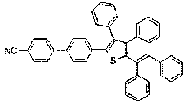
590 1-2-7 compound 1-2-7 
741 1-2-8 compound 1-2-8 
741 1-2-9 compound 1-2-9 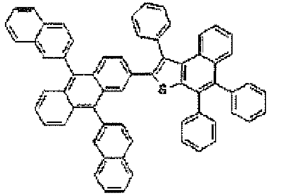
841 1-2-10 compound 1-2-10 
817 1-2-11 compound 1-2-11 
791 1-2-12 compound 1-2-12 
791 1-2-13 compound 1-2-13 
975 1-2-14 compound 1-2-14 
681 1-2-15 compound 1-2-15 
781 1-2-16 compound 1-2-16 
613 1-2-17 compound 1-2-17 
1023 1-2-16 compound 1-2-16 
719 1-2-17 compound 1-2-17 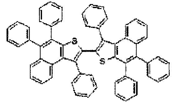
823 1-2-18 compound 1-2-18 
808 1-2-19 compound 1-2-19 
808 1-2-20 compound 1-2-20 
884 -

- Phenyl boronic acid (2.5 g, 20.5 mmol), the compound 1E-3-4 (5.6 g, 9.3 mmol) that was prepared in Synthesis Example 1-10-4, and sodium carbonate (2.8 g, 20.5 mmol) were suspended in the mixture of tetrahydrofurane (100 mL) and water (50 mL). Tetrakis(triphenylphosphine)palladium (0.1 g, 0.2 mmol) was applied to the suspension solution. The mixture was refluxed and agitated for about 24 hours, and the refluxed mixture was cooled to room temperature. The prepared solid was purified with filtered THF/EtOH to prepare the compound 1-3-1 (3.2 g, yield 46%).
MS [M+H]+= 741 - In Preparation Example 1-3-1, it was prepared by using the same method to prepare the compound 1-3-2, except that the compound of 1E-3-6 synthesized in Synthesis Example 1-10-6 was used.
- In Preparation Example 1-3-1, it was prepared by using the same method to prepare the compound 1-3-3, except that the compound of 1E-3-7 synthesized in Synthesis Example 1-10-7 was used.
- In Preparation Example 1-3-1, it was prepared by using the same method to prepare the compound 1-3-4, except that the compound of 1E-3-8 synthesized in Synthesis Example 1-10-8 was used.
[TABLE 1-3] Prep. Ex. 1-3-No Product 1-3-No structure MS [M+H]+ 1-3-1 compound 1-3-1 
741 1-3-2 compound 1-3-2 
817 1-3-3 compound 1-3-3 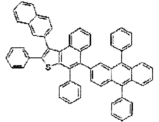
665 1-3-4 compound 1-3-4 
822 - In Preparation Example 1-4-2, the compound 1-4-1 was prepared by using the same method, except that phenyl boronic acid was used instead of naphthyl boronic acid.
-

- Naphthyl boronic acid (3.5 g, 20.5 mmol), the compound 1E-3-2 (5.6 g, 9.3 mmol) that was prepared in Synthesis Example 1-10-2, and sodium carbonate (2.8 g, 20.5 mmol) were suspended in the mixture of tetrahydrofurane (100 mL) and water (50 mL). Tetrakis(triphenylphosphine)palladium (0.1 g, 0.2 mmol) was applied to the suspension solution. The mixture was refluxed and agitated for about 24 hours, and the refluxed mixture was cooled to room temperature. The prepared solid was purified with filtered THF/EtOH to prepare the compound 1-4-2 (3.2 g, yield 46%).
- In Preparation Example 1-4-1, it was prepared by using the same method to prepare the compound 1-4-3, except that the compound of 1E-3-2 synthesized in Synthesis Example 1-10-2 was used.
[TABLE 1-4] Prep. Ex. 1-4-No Product 1-4-No structure MS [M+H]+ 1-4-1 compound 1-4-1 
791 1-4-2 compound 1-4-2 
841 1-4-3 compound 1-4-3 
841 -

- In Preparation Example z-2, it was prepared by using the same method to prepare the compound 1-12-1, except that phenyl boronic acid was used instead of naphthyl boronic acid and the compound 1E-4-1 was used instead of the compound 1E-3-2.
- The compound 1-12-1 (20.2 g, 38.6 mmol), and the reactant S-28 (12.4 g, 38.6 mmol) were dissolved in 200 ml of xylene, 5.6 g of sodium-tertiary-botoxide (57.9 mmol), and Pd[P(t-Bu)3]2 (0.19 g, 0.386 mmol) were added thereto, and refluxed for 5 hours under the nitrogen atmosphere. Distilled water was put into the reaction solution, the termination of the reaction was carried out, and the organic material layer was extracted. After the column separation was carried out with normal-hexane/tetrahydrofurane = 10/1 solvent, it was agitated in petroleum ether, and dried under vacuum to manufacture the compound 1-5-1 (22.5 g, yield 72%).
-

- In Preparation Example 1-4-2, it was prepared by using the same method to prepare the compound 1-12-3, except that phenyl boronic acid was used instead of naphthyl boronic acid and the compound 1E-4-3 was used instead of the compound 1E-3-2.
- In Preparation Example 1-5-1, the compound 1-5-2 was prepared by using the same method, except that the compound 1-12-3 was used instead of the compound 1-12-1.
-

- In Preparation Example 1-4-2, it was prepared by using the same method to prepare the compound 1-12-6, except that the reactant S-18 was used instead of naphthyl boronic acid and the compound 1E-4-1 was used instead of the compound 1E-3-2.
- In Preparation Example 1-5-1, the compound 1-5-3 was prepared by using the same method, except that the compound 1-12-6 was used instead of the compound 1-12-1 and the reactant S-30 was used instead of the reactant S-28.
-

- In Preparation Example 1-4-2, it was prepared by using the same method to prepare the compound 1-12-2, except that phenyl boronic acid was used instead of naphthyl boronic acid and the compound 1E-4-2 was used instead of the compound 1E-3-2.
- In Preparation Example 1-5-1, the compound 1-5-4 was prepared by using the same method, except that the compound 1-12-2 was used instead of the compound 1-1.2-1 and the reactant S-29 was used instead of the reactant 8-28.
- In Preparation Example 1-5-1, the compound 1-5-5 was prepared by using the same method, except that the reactant S-27 was used instead of the reactant S-28.
[TABLE 1-5] Prep. Ex. 1-5-No Product 1-5-No structure MS [M+H]+ 1-5-1 compound 1-5-1 
808 1-5-2 compound 1-5-2 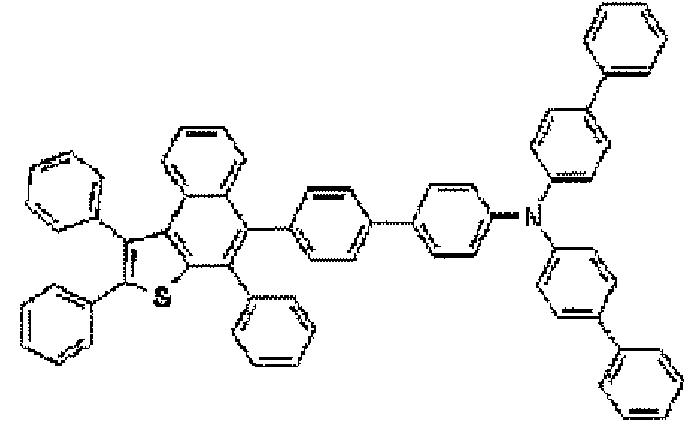
885 1-5-3 compound 1-5-3 
819 1-5-4 compound 1-5-4 
782 1-5-5 compound 1-5-5 
823 -

- In Preparation Example 1-4-2, it was prepared by using the same method to prepare the compound 1-12-7, except that the reactant S-14 was used instead of naphthyl boronic acid and the compound 1E-2-1 was used instead of the compound 1E-3-2.
- In Preparation Example 1-5-1, the compound 1-6-1 was prepared by using the same method, except that the compound 1-12-7 was used instead of the compound 1-12-1 and the reactant S-30 was used instead of the reactant S-28.
-

- In Preparation Example 1-4-2, it was prepared by using the same method to prepare the compound 1-12-8, except that the reactant S-13 was used instead of naphthyl boronic acid and the compound 1E-2-1 was used instead of the compound 1E-3-2.
- In Preparation Example 1-5-1, the compound 1-6-2 was prepared by using the same method, except that the compound 1-12-8 was used instead of the compound 1-12-1 and the reactant S-30 was used instead of the reactant S-28.
- In Preparation Example 1-5-1, the compound 1-6-3 was prepared by using the same method, except that the compound 1-12-7 was used instead of the compound 1-12-1.
[TABLE 1-6] Prep. Ex. 1-6-No Product 1-6-No structure MS [M+H]+ 1-6-1 compound 1-6-1 
730 1-6-2 compound 1-6-2 
808 1-6-3 compound 1-6-3 
884 - In Preparation Example 1-4-2, it was prepared by using the same method to prepare the compound 1-7-1, except that phenyl boronic acid compound was used instead of naphthyl boronic acid and the compound 1E-3-3 was used instead of the compound 1E-3-2.
- In Preparation Example 1-4-2, it was prepared by using the same method to prepare the compound 1-7-2, except that phenyl boronic acid compound was used instead of naphthyl boronic acid and the compound 1E-3-9 was used instead of the compound 1E-3-2.
- In Preparation Example 1-4-2, it was prepared by using the same method to prepare the compound 1-7-3, except that phenyl boronic acid compound was used instead of naphthyl boronic acid and the compound 1E-3-5 was used instead of the compound 1E-3-2.
[TABLE 1-7] Prep. Ex. 1-7-No Product 1-7-No structure MS [M+H]+ 1-7-1 compound 1-7-1 
741 1-7-2 compound 1-7-2 
885 1-7-3 compound 1-7-3 
841 - In Preparation Example 1-4-2, it was prepared by using the same method to prepare the compound 2-1-1, except that the reactant S-10 was used instead of naphthyl boronic acid and the compound 2E-1-1 was used instead of the compound 1E-3-2.
- In Preparation Example 1-4-2, it was prepared by using the same method to prepare the compound 2-1-2, except that the reactant S-31 was used instead of naphthyl boronic acid and the compound 2E-1-2 was used instead of the compound 1E-3-2.
- In Preparation Example 1-4-2, it was prepared by using the same method to prepare the compound 2-1-3, except that phenyl boronic acid compound was used instead of naphthyl boronic acid and the compound 2E-1-4 was used instead of the compound 1E-3-2.
- In Preparation Example 1-4-2, it was prepared by using the same method to prepare the compound 2-1-4, except that phenyl boronic acid was used instead of naphthyl boronic acid and the compound 2E-1-6 was used instead of the compound 1E-3-2.
- In Preparation Example 1-4-2, it was prepared by using the same method to prepare the compound 2-1-5, except that phenyl boronic acid was used instead of naphthyl boronic acid and the compound 2E-1-5 was used instead of the compound 1E-3-2.
- In Preparation Example 1-4-2, it was prepared by using the same method to prepare the compound 2-1-6, except that the reactant S-33 was used instead of naphthyl boronic acid in an equivalent of 2.4 and the compound 2E-1-1 was used instead of the compound 1E-3-2.
[TABLE 2-1] Prep. Ex. 2-1-No Product 2-1-No structure MS [M+H]+ 2-1-1 compound 2-1-1 
776 2-1-2 compound 2-1-2 
749 2-1-3 compound 2-1-3 
775 2-1-4 compound 2-1-4 
730 2-1-5 compound 2-1-5 
801 2-1-6 2-1-6 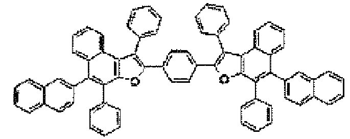
967 -

- 2-[9,10-diphenyl-2-anthracenyl]-4,4,5,5-tetramethyl-1,3,2-dioxaborolane (2.2 g, 4.9 mmol) that was the reactant S-10, the prepared compound A-3 (1.8 g, 4.1 mmol), and sodium carbonate (1.4 g, 10.0 mmol) were suspended in the mixture of tetrahydrofurane (100 mL) and water (50 mL). Tetrakis(triphenylphosphine)palladium (0.1 g, 0.1 mmol) was applied to the suspension solution. The mixture was refluxed and agitated for about 24 hours, and the refluxed mixture was cooled to room temperature. The prepared solid was purified with filtered THF/EtOH to prepare the compound 3-1-2 (2.1 g, yield 68%).
-

- 2-[9,10-di-2-naphthalenyl-2-anthracenyl]-4,4,5,5,-tetramethyl-1,3,2-dioxaborolane (2.7 g, 4.9 mmol) that was the reactant S-9, the prepared compound A-3 (1.8 g, 4.1 mmol), and sodium carbonate (1.4 g, 10.0 mmol) were suspended in the mixture of tetrahydrofurane (100 mL) and water (50 mL). Tetrakis(triphenylphosphine)palladium (0.1 g, 0.1 mmol) was applied to the suspension solution. The mixture was refluxed and agitated for about 24 hours, and the refluxed mixture was cooled to room temperature. The prepared solid was purified with filtered THF/EtOH to prepare the compound 3-1-3 (2.5 g, yield 82%).
-
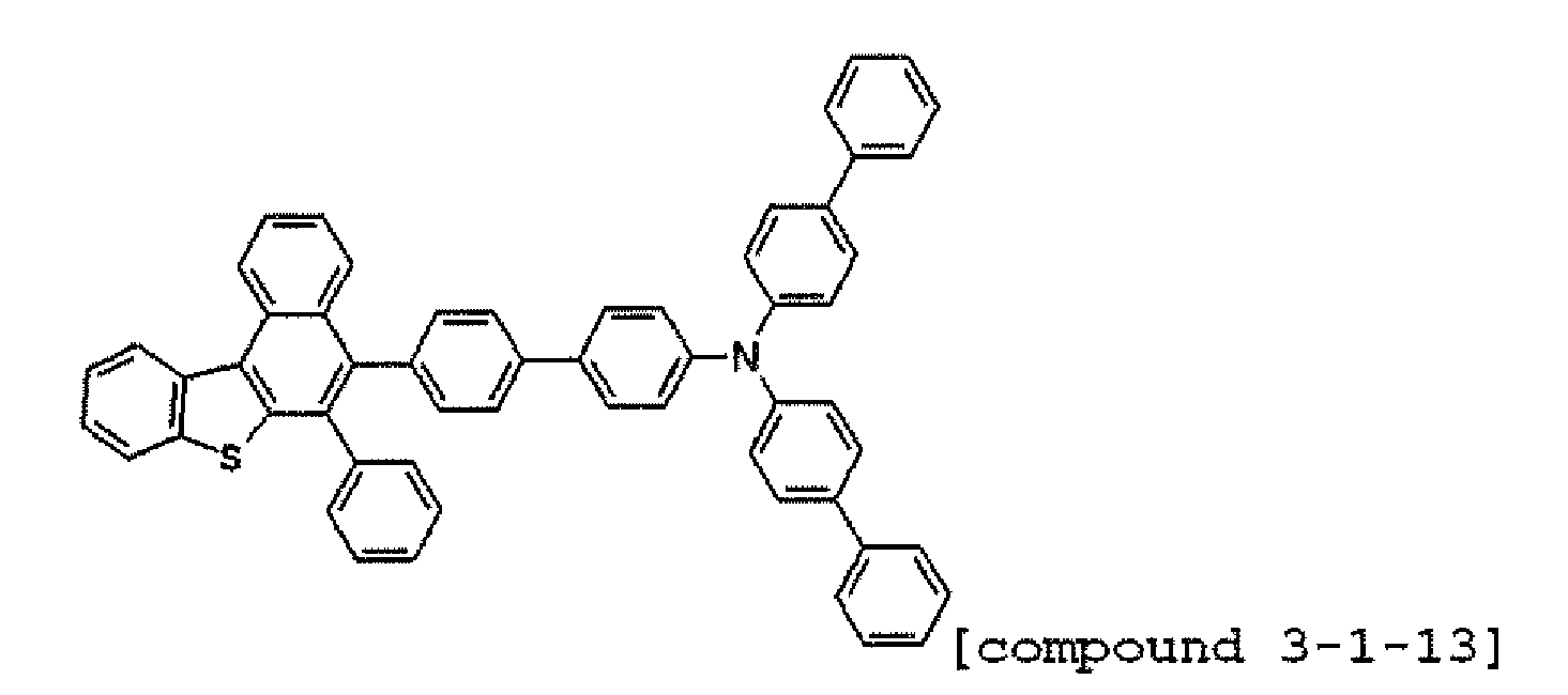
- 4'-(dibiphenylamino)(1,1'-biphenyl)-4-yl boronic acid (2.5 g, 4.9 mmol) that was the reactant S-23, the prepared compound A-3 (1.8 g, 4.1 mmol), and sodium carbonate (1.4 g, 10.0 mmol) were suspended in the mixture of tetrahydrofurane (100 mL) and water (50 mL). Tetrakis(triphenylphosphine)palladium (0.1 g, 0.1 mmol) was applied to the suspension solution. The mixture was refluxed and agitated for about 24 hours, and the refluxed mixture was cooled to room temperature. The prepared solid was purified with filtered THF/EtOH to prepare the compound 3-1-13 (1.8 g, yield 56%).
-

- The reactant S-23 (1.9 g, 4.9 mmol), the prepared compound A-3 (1.8 g, 4.1 mmol), and sodium carbonate (1.4 g, 10.0 mmol) were suspended in the mixture of tetrahydrofurane (100 mL) and water (50 mL). Tetrakis(triphenylphosphine)palladium (0.1 g, (3.1 mmol) was applied to the suspension solution. The mixture was refluxed and agitated for about 24 hours, and the refluxed mixture was cooled to room temperature. The prepared solid was purified with filtered THF/EtOH to prepare the compound 3-1-15 (1.5 g, yield 47%).
-

- 4-[9-(2-naphthyl-10-phenylene]-4,4,5,5-tetramethyl-1,3,2-dioxaborolane (2.2 g, 4.9 mmol) that was the reactant S-33, the prepared compound A-3 (1.8 g, 4.1 mmol), and sodium carbonate (1.4 g, 10.0 mmol) were suspended in the mixture of tetrahydrofurane (100 mL) and water (50 mL). Tetrakis(triphenylphosphine)palladium (0.1 g, 0.1 mmol) was applied to the suspension solution. The mixture was refluxed and agitated for about 24 hours, and the refluxed mixture was cooled to room temperature. The prepared solid was purified with filtered THF/EtOH to prepare the compound 3-1-16(1.47 g, yield 52%).
- In Preparation Example 3-1-16, the compound 3-1-1 was prepared by using the same method, except that the reactant S-10 was used instead of the reactant S-33.
- In Preparation Example 3-1-16, the compound 3-1-4 was prepared by using the same method, except that the reactant S-5 was used instead of the reactant S-33.
- In Preparation Example 3-1-16, the compound 3-1-5 was prepared by using the same method, except that the reactant S-8 was used instead of the reactant S-33.
- In Preparation Example 3-1-16, it was prepared by using the same method to prepare the compound 3-1-6, except that the reactant S-7 was used instead of the reactant S-33.
- In Preparation Example 3-1-16, it was prepared by using the same method to prepare the compound 3-1-7, except that the reactant S-31 was used instead of the reactant S-33.
- In Preparation Example 3-1-16, it was prepared by using the same method to prepare the compound 3-1-8. except that the reactant S-38 was used instead of the reactant S-33.
- In Preparation Example 3-1-16, it was prepared by using the same method to prepare the compound 3-1-9, except that the reactant S-39 was used instead of the reactant S-33.
- In Preparation Example 3-1-16, it was prepared by using the same method to prepare the compound 3-1-10, except that the reactant S-36 was used instead of the reactant S-33.
- In Preparation Example 3-1-16, it was prepared by using the same method to prepare the compound 3-1-11, except that the reactant S-35 was used instead of the reactant S-33.
- In Preparation Example 3-1-16, it was prepared by using the same method to prepare the compound 3-1-12, except that the reactant S-34 was used instead of the reactant S-33.
[TABLE 3-1] Prep. Ex. 3-1-No Product 3-1-No structure MS [M+H] + 3-1-1 compound 3-1-1 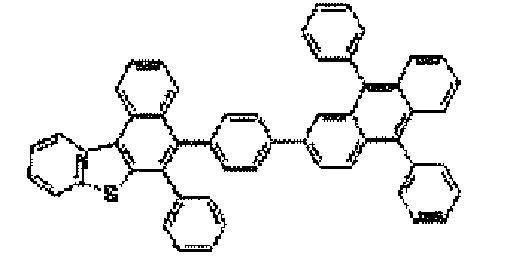
715 3-1-2 compound 3-1-2 
639 3-1-3 compound 3-1-3 
739 3-1-4 compound 3-1-4 
680 3-1-5 compound 3-1-5 
639 3-1-6 compound 3-1-6 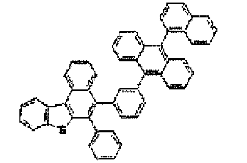
689 3-1-7 compound 3-1-7 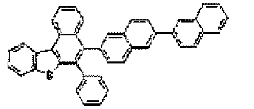
563 3-1-8 compound 3-1-8 
655 3-1-9 compound 3-1-9 
628 3-1-10 compound 3-1-10 
783 3-1-11 compound 3-1-11 
587 3-1-12 compound 3-1-12 
565 3-1-13 compound 3-1-13 
782 3-1-14 compound 3-1-14 
771 3-1-15 compound 3-1-15 
771 3-1-16 compound 3-1-16 
689 3-1-17 compound 3-1-17 
953 3-1-18 compound 3-1-18 
873 3-1-19 compound 3-1-19 
771 3-1-20 compound 3-1-20 
719 - In Preparation Example 1-5-1, the compound 3-1-17 was prepared by using the same method, except that 2.4 equivalents of the compound A-3 and 4.8 equivalents of sodium-tertiary-botoxide were used instead of the compound 1-12-1 and the reactant S-41 was used instead of the reactant S-28.
- In Preparation Example 1-5-1, the compound 3-1-18 was prepared by using the same method, except that the compound A-3 was used instead of the compound 1-12-1 and the reactant S-43 was used instead of the reactant S-28.
- In Preparation Example 1-5-1, the compound 3-1-19 was prepared by using the same method, except that the compound A-3 was used instead of the compound 1-12-1 and the reactant S-44 was used instead of the reactant S-28.
- In Preparation Example 1-5-1, the compound 3-1-20 was prepared by using the same method, except that the compound A-3 was used instead of the compound 1-12-1 and the reactant S-42 was used instead of the reactant S-28.
-

- The reactant S-15 (1.5 g, 4.9 mmol), the prepared compound A-4 (1.7 g, 4.1 mmol), and sodium carbonate (1.4 g, 10.0 mmol) were suspended in the mixture of tetrahydrofurane (100 mL) and water (50 mL). Tetrakis(triphenylphosphine)palladium (0.1 g, 0.1 mmol) was applied to the suspension solution. The mixture was refluxed and agitated for about 24 hours, and the refluxed mixture was cooled to room temperature. The prepared solid was purified with filtered THF/EtOH to prepare the compound 4-1-14 (2.3 g, yield 82%).
- In Preparation Example 4-1-14, it was prepared by using the same method to prepare the compounds 4-1-1 to 4-1-12, except that the reactants S-22, S-10, S-9, S-5. S-8, S-7, S-31, S-38, S-36, S-34, and S-25 were used instead of the reactant S-15.
- In Preparation Example 4-1-14, it was prepared by using the same method to prepare the compound 4-1-13, except that the reactant S-23 was used instead of the reactant S-15 in an equaivalent of 2.4.
[TABLE 4-1] Prep. Ex. 4-1-No Product 4-1-No structure MS [M+H]+ 4-1-1 compound 4-1-1 
699 4-1-2 compound 4-1-2 
623 4-1-3 compound 4-1-3 
723 4-1-4 compound 4-1-4 
673 4-1-5 compound 4-1-5 
623 4-1-6 compound 4-1-6 
673 4-1-7 compound 4-1-7 
547 4-1-8 compound 4-1-8 
639 4-1-9 compound 4-1-9 
767 4-1-10 compound 4-1-10 
549 4-1-11 compound 4-1-11 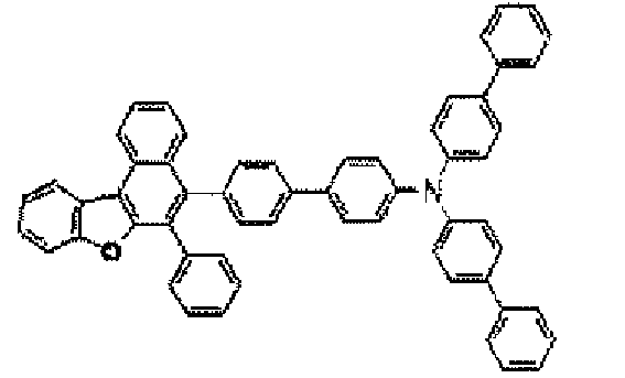
766 4-1-12 compound 4-1-12 
755 4-1-13 compound 4-1-13 
739 4-1-14 compound 4-1-14 
563 -

- In Preparation Example 3-1-16, it was prepared by using the same method to prepare the compound A-5, except that the phenyl boronic acid that was the reactant S-3 was used instead of the reactant S-33.
- After the compound B-5-1 (4.6 g, 12.0 mmol) was dissolved in DMF 60 mL, NBS (2.2 g, 12.0 mmol) was applied thereto and agitated at normal temperature for 2 hours. After water 120 mL was applied thereto to precipitate the solid, it was filtered, washed with ethanol, and dried to prepare the compound C-5-1 (3.8 g, yield 68%).
MS [M]+ = 465 - In Preparation Example 3-1-16, the compound 5-1-1 was prepared by using the same method, except that the compound A-5 was used instead of the compound A-3 and the reactant S-26 was used instead of the reactant S-33.
- In Preparation Example 3-1-16, the compound 5-1-2 was prepared by using the same method, except that the compound A-5 was used instead of the compound A-3 and the reactant S-16 was used instead of the reactant S-33.
- In Preparation Example 3-1-16, the compound 5-1-3 was prepared by using the same method, except that the compound A-5 was used instead of the compound A-3 and the reactant S-40 was used instead of the reactant S-33.
[TABLE 5-1] Prep. Ex. 5-1-No Product 5-1-No structure MS [M+H]+ 5-1-1 compound 5-1-1 
782 5-1-2 compound 5-1-2 
694 5-1-3 compound 5-1-3 
689 - A glass substrate on which a thin film of ITO (indium tin oxide) was coated to a thickness of 1500 Å was immersed in distilled water having a detergent dissolved therein to wash the substrate with ultrasonic waves. At this time, the detergent as used herein was a product commercially available from Fisher Co. and the distilled water was one which had been twice filtered by using a filter commercially available from Millipore Co. ITO was washed for 30 minutes, and then washing with ultrasonic waves was repeated twice for 10 minutes by using distilled water. After the completion of washing with distilled water, washing with ultrasonic waves was subsequently carried out by using solvents such as isopropyl alcohol, acetone and methanol, the resultant product was dried, and transported to the plasma washing machine. In addition, the substrate was washed by using the oxygen plasma for 5 min, and the substrate was transported to the vacuum deposition machine.
- On the ITO transparent electrode thus prepared, hexanitrile hexaazatriphenylene was coated to thicknesses of 500 Å by thermal vacuum deposition to form a hole injecting layer. After NPB (400 Å) that was the material transporting the holes was deposited under the vacuum state thereon, the host H1 and the dopant D1 compound were deposited under the vacuum state in a thickness of 300 Å as a light emitting layer.

- On the light emitting layer, the compound 1-1-10- prepared in Preparation Example 1-1-10 was deposited under the vacuum state in a thickness of 200 Å to form the electron injection and transport layer. On the electron injection and transport layer, lithium fluoride (LiF) in a thickness of 12 Å and aluminium in a thickness of 2000 Å were subsequently deposited to form a cathode.
- In the above process, the deposition speed of the organic substance was maintained at 1 Å/sec, that of lithium fluoride was maintained at 0.2 Å/sec, and that of aluminium was maintained at 3 to 7 Å/sec.
- In Experimental Example 1-1, the same experiment was performed, except that on the light emitting layer, the compounds 1-1-11, 1-1-14, 1-2-1, 1-2-5, 1-2-11, 1-2-14, 3-1-8, 3-1-12, 4-1-8, 4-1-10, 4-1-14, and 5-1-2 were used instead of the compound 1-1-10 prepared in Preparation Example 1-1-10.
- In Experimental Example 1-1, the same experiment was performed, except that on the light emitting layer, the compound Alq3 was used instead of the compound 1-1-10.

- Like Experimental Examples 1-1 to 1-12 and Comparative Example 1, the test results of the organic light emitting device that was prepared by using each compound as the electron injection and transport layer material are described in Table 11.
[TABLE 11] Exp. Ex. 100mA/cm2 compound Voltage (V) Cur. Eff. (cd/A) Color Coordinate (x,y) Com. Ex. 1 Alq3 10.91 10.96 (0.323, 0.644) Exp. Ex. 1-1 1-1-10 7.76 21.06 (0.317, 0.649) Exp. Ex.1-2 1-1-11 7.05 24.22 (0.323, 0.647) Exp. Ex.1-3 1-1-14 8.14 24.28 (0.314, 0.650) Exp. Ex. 1-4 1-2-1 6.91 23.27 (0.310, 0.652) Exp. Ex. 1-5 1-2-5 8.29 24.63 (0.318. 0.653) Exp. Ex. 1-6 1-2-11 8.91 18.44 (0.317, 0.645) Exp. Ex. 1-7 1-2-14 8.28 18.61 (0.318, 0.652) Exp. Ex. 1-8 3-1-8 7.31 21.12 (0.318, 0.658) Exp. Ex. 1-9 3-1-12 7.12 24.34 (0.319, 0.657) Exp. Ex. 1-10 4-1-8 8.19 24.65 (0.318, 0.658) Exp. Ex. 1-11 4-1-10 8.37 22.52 (0.318, 0.653) Exp. Ex. 1-11 4-1-14 8.31 22.91 (0.317, 0.651) Exp. Ex. 1-12 5-1-2 8.32 20.98 (0.317, 0.653) - As shown in the results of Table 11, properties are improved in terms of low voltage and efficiency in comparison with the results of the device of Comparative Example 1. In the compounds of Table 11, the substituent group having relatively excellent electron injection and transport properties is introduced. The properties of them are not lowered but improved by the basic structure of Formula 1. This is because the structure of Formula 1 has an appropriate LUMO so as to easily transport electrons to the light emitting layer by introducing the frame having the relatively large energy band gap or the substituent groups having the electron injection and transport properties.
- A glass substrate on which a thin film of ITO (indium tin oxide) was coated to a thickness of 1500 Å was immersed in distilled water having a detergent dissolved therein to wash the substrate with ultrasonic waves. At this time, the detergent as used herein was a product commercially available from Fisher Co. and the distilled water was one which had been twice filtered by using a filter commercially available from Millipore Co. ITO was washed for 30 minutes, and then washing with ultrasonic waves was repeated twice for 10 minutes by using distilled water. After the completion of washing with distilled water, washing with ultrasonic waves was subsequently carried out by using solvents such as isopropyl alcohol, acetone and methanol, the resultant product was dried, and transported to the plasma washing machine. In addition, the substrate was washed by using the oxygen plasma for 5 min, and the substrate was transported to the vacuum deposition machine.
- On the ITO transparent electrode thus prepared, hexanitrile hexaazatriphenylene was coated to thicknesses of 500 Å by thermal vacuum deposition to form a hole injecting layer. After NPB (400 Å) that was the material transporting the holes was deposited under the vacuum state thereon, the compound 1-1-7 that was prepared in Preparation Example 1-1-7 as the host H1 and the dopant D1 compound were deposited under the vacuum state in a thickness of 300 Å as a light emitting layer. On the light emitting layer, the electron injection and transport layer was formed by depositing E1 under the vacuum state in a thickness of 200 Å on the light emitting layer. On the electron transport layer, lithium fluoride (LiF) in a thickness of 12 Å and aluminium in a thickness of 2000 Å were subsequently deposited to form a cathode, thereby manufacturing the organic light emitting device.
- In the above process, the deposition speed of the organic material was maintained at 0.4 to 0.7 Å/sec, the deposition speed of the lithium fluoride of the cathode was maintained at 0.3 Å/see, the deposition speed of aluminium was maintained at 2 Å/see, and the degree of vacuum in the deposition was maintained at 2 × 10⁻⁷ to 5 × 10⁻⁸ torr.
- In Experimental Example 2-1, the organic light emitting device was experimented by using the same method, except that the compounds 1-1-6, 1-2-6, 1-2-7, 1-2-8, 1-2-9, 1-2-10, 1-2-12, 1-2-13, 1-3-1, 1-3-2, 1-3-3, 1-3-4, 1-4-1, 1-4-2, 1-4-3, 1-7-1, 1-7-3, 2-1-1, 2-1-3, 2-1-4, 2-1-5, 3-1-1, 3-1-2, 3-1-3, 3-1-4, 3-1-5, 3-1-6, 4-1-1, 4-1-2, 4-1-3, 4-1-4, 4-1-5, 4-1-6, 4-1-7, and 5-1-3 were used instead of the compound 1-1-7 on the hole transport layer, and the results thereof are described in Table 12.
[TABLE 12] Exp. Ex. 100mA/cm2 Host Material Dopant Material Voltage (V) Cur. Eff. (cd/A) Color Coordinate (x, y) Exp. Ex. 2-1 1-1-7 D1 7.34 23.35 (0.314, 0.652) Exp. Ex. 2-2 1-1-6 D1 7.61 21.62 (0.314, 0.650) Exp. Ex. 2-3 1-2-6 D1 8.82 22.04 (0.315, 0.648) Exp. Ex. 2-4 1-2-7 D1 8.09 21.63 (0.317, 0.650) Exp. Ex. 2-5 1-2-8 D1 7.67 23.06 (0.315, 0.651) Exp. Ex. 2-6 1-2-9 D1 8.67 20.23 (0.315, 0.650) Exp. Ex. 2-7 1-2-10 D1 10.51 16.26 (0.314, 0.650) Exp. Ex. 2-8 1-2-12 D1 10.06 20.46 (0.317, 0.650) Exp. Ex. 2-9 1-2-13 D1 8.08 21.40 (0.317, 0.647) Exp. Ex. 2-10 1-3-1 D1 8.05 26-10 (0.315, 0.648) Exp. Ex. 2-11 1-3-2 D1 8.01 26.18 (0.316, 0.648) Exp. Ex. 2-12 1-3-3 D1 7.62 20.26 (0.314, 0.650) Exp. Ex. 2-13 1-3-4 D1 8.01 21.36 (0.317, 0.650) Exp. Ex. 2-14 1-4-1 D1 7.65 23.63 (0.315, 0.651) Exp. Ex. 2-15 1-4-2 D1 8.53 22.21 (0.315, 0.650) Exp. Ex. 2-16 1-4-S D1 8.10 20.05 (0.314, 0.650) Exp. Ex. 2-17 1-7-1 D1 11.71 24.02 (0.319, 0,649) Exp. Ex. 2-18 1-7-3 D1 10,32 21.46 (0.317, 0.650) Exp. Ex. 2-19 2-1-1 D1 8.23 23.40 (0.317, 0.647) Exp. Ex. 2-20 2-1-3 D1 8.91 22.02 (0.319, 0.649) Exp. Ex. 2-21 2-1-4 D1 7.22 22.10 (0.315, 0.648) Exp. Ex. 2-22 2-1-5 D1 7.67 20.06 (0.315, 0.651) Exp. Ex. 2-23 3-1-1 D1 7.15 21.06 (0.315, 0.651) Exp. Ex. 2-24 3-1-2 D1 8.47 21.23 (0.315, 0.650) Exp. Ex. 2-25 3-1-3 D1 8.85 22.08 (0.317, 0.648) Exp. Ex. 2-26 3-1-4 D1 7.66 20.57 (0.315, 0.649) Exp. Ex. 2-27 3-1-5 D1 7.46 21.22 (0.316, 0.652) Exp. Ex. 2-28 3-1-6 D1 7.98 19.98 (0.314, 0.652) Exp. Ex. 2-29 4-1-1 D1 8.38 19.89 (0.314. 0.650) Exp. Ex. 2-30 4-1-2 D1 8.32 21.89 (0.315, 0.647) Exp. Ex. 2-31 4-1-3 D1 7-55 20.02 (0.319, 0,649) Exp. Ex. 2-32 4-1-4 D1 7.97 23.07 (0.318, 0.651) Exp. Ex. 2-33 4-1-5 D1 8.29 24.01 (0.317, 0.649) Exp. Ex. 2-34 4-1-6 D1 8.43 20.78 (0.317, 0.651) Exp. Ex. 2-35 4-1-7 D1 9.03 16-56 (0.317, 0.650) Exp. Ex. 2-36 5-1-3 D1 8.81 23.80 (0.317, 0.647) - As shown in the results of Table 12, the compounds of Formula 1 may be used as the light emitting layer in conjunction with the dopant by introducing the aryl group such as anthracene.
- A glass substrate (coming 7059 glass) on which a thin film of ITO (indium tin oxide) was coated to a thickness of 1000 Å was immersed in distilled water having a detergent dissolved therein to wash the substrate with ultrasonic waves. The detergent as used herein was a product commercially available from Fisher Co. and the distilled water was one which had been twice filtered by using a filter commercially available from Millipore Co. ITO was washed for 30 minutes, and then washing with ultrasonic waves was repeated twice for 10 minutes by using distilled water. After the completion of washing with distilled water, washing with ultrasonic waves was carried out by using solvents such as isopropyl alcohol, acetone and methanol, and the resultant product was dried.
- On the ITO transparent electrode thus prepared, hexanitrile hexaazatriphenylene was coated to thicknesses of 500 Å by thermal vacuum deposition to form a hole injecting layer. After the compound 1-5-1 (400 Å) prepared in Preparation Example 1-5-1, which was the material transporting the holes was deposited under the vacuum state thereon, the host H1 and the dopant D1 compound were deposited under the vacuum state in a thickness of 300 Å as a light emitting layer. Thereafter, the E1 compound (300 Å) was deposited by heating under the vacuum as the electron injection and the transport layer. On the electron transport layer, lithium fluoride (LiF) in a thickness of 12 Å and aluminium in a thickness of 2,000 Å were subsequently deposited to form a cathode, thereby manufacturing the organic light emitting device.
- In the above process, the deposition speed of the organic substance was maintained at 1 Å/sec, that of lithium fluoride was maintained at 0.2 Å/sec, and that of aluminium was maintained at 3 to 7 Å/sec.
- In Experimental Example 3-1, the organic light emitting device was experimented by using the same method, except that the compounds 11-5-2, 1-5-3, 1-5-4, 1-5-5, 1-6-1, 1-6-2, 1-6-3, 3-1-13, 3-1-14, 3-1-15, 4-1-11, 4-1-12, 5-1-1, 3-1-17, 3-1-18, 3-1-19, and 3-1-20 were used, and the results thereof are described in Table 13.
[TABLE 13] Exp. Ex. 100mA/cm2 HTL Material Voltage (V) Cur. Eff. (cd/A) Color Coordinate (x,y) Com. Ex. 2 NPB 8.89 21.23 (0.323, 0.644) Exp. Ex. 3-1 1-5-1 7.17 22.05 (0.316, 0.650) Exp. Ex. 3-2 1-5-2 6.49 19.08 (0.312, 0.650) Exp. Ex. 3-3 1-5-3 7.28 20.53 (0.315, 0.648) Exp. Ex. 3-4 1-5-4 7.73 23.72 (0.310, 0.647) Exp. Ex. 3-5 1-5-5 6.88 21.11 (0.312, 0.651) Exp. Ex. 3-6 1-6-1 6.17 20.05 (0.313, 0.650) Exp. Ex. 3-7 1-6-2 7.28 21.53 (0.315, 0.648) Exp. Ex. 3-8 1-6-3 7.73 24.72 (0.310, 0.65(13 Exp. Ex. 3-9 3-1-13 6.89 21.67 (0.313, 0.651) Exp. Ex. 3-10 3-1-14 7.02 21.05 (0.317, 0.650) Exp. Ex. 3-11 3-1-15 9.07 18.88 (0.315, 0.651) Exp. Ex. 3-12 4-1-11 7.27 21.87 (0.312, 0.650) Exp. Ex. 3-13 4-1-12 7.98 22.43 (0.314, 0.648) Exp. Ex. 3-14 5-1-1 7.48 20.07 (0.314, 0.650) Exp. Ex. 3-15 3-1-17 8.21 21.10 (0.316, 0.649) Exp. Ex. 3-16 3-1-18 7.68 22.02 (0.318, 0.648) Exp. Ex. 3-17 3-1-19 7.74 20.19 (0.317, 0.650) Exp. Ex. 3-18 3-1-20 7.51 19.78 (0.312, 0.648) - As shown in the results of Table 13, in the compound of Formula 1, low voltage and efficiency increase may be obtained by using the compounds that were prepared by introducing the aryl group substituted by the arylamin group as the hole transport layer.
- A glass substrate (coming 7059 glass) on which a thin film of ITO (indium tin oxide) was coated to a thickness of 1000 Å was immersed in distilled water having a detergent dissolved therein to wash the substrate with ultrasonic waves. The detergent as used herein was a product commercially available from Fisher Co. and the distilled water was one which had been twice filtered by using a filter commercially available from Millipore Co. ITO was washed for 30 minutes, and then washing with ultrasonic waves was repeated twice for 10 minutes by using distilled water. After the completion of washing with distilled water, washing with ultrasonic waves was carried out by using solvents such as isopropyl alcohol, acetone and methanol, and the resultant product was dried.
- On the ITO transparent electrode thus prepared, hexanitrile hexaazatriphenylene was coated to thicknesses of 500 Å by thermal vacuum deposition to form a hole injecting layer. NPB (400 Å) was deposited under the vacuum state as the material transporting the holes thereon. As the light emitting layer, the compound 3-1-10 prepared in Preparation Example 3-1-10 and the dopant D2 (doping concentration 14%) compound were deposited under the vacuum state in a thickness of 300 Å.

- Thereafter, the E1 compound (300 Å) was deposited by heating under the vacuum as the electron injection and the transport layer. On the electron transport layer, lithium fluoride (LiF) in a thickness of 12 Å and aluminium in a thickness of 2,000 Å were subsequently deposited to form a cathode, thereby manufacturing the organic light emitting device.
- In the above process, the deposition speed of the organic substance was maintained at 1 Å/sec, that of lithium fluoride was maintained at 0.2 Å/sec, and that of aluminium was maintained at 3 to 7 Å/sec.
- In Experimental Example 4-1, the compounds represented by Formulas 1-1-13, 1-1-14, 1-2-1, 1-2-4, 1-5-2, 1-5-3, 1-6-1, 3-1-9, and 4-1-9 were used instead of the compound 3-1-10, and the organic light emitting device was manufactured by using the compound E1, and the experimental results thereof are described in the following Table 14.
- In Experimental Example 4-1, the same experiment was performed, except that the compound H2 was used instead of the compound 3-1-10.
[TABLE 14] Exp. Ex. 20 mA/cm2 EML (Host:D3) Voltage (V) Cur. Eff. (cd/A) Color Coordinate (x, y) Com. Ex. 3 H2 6.74 16.28 (0.371, 0.595) Exp. Ex. 4-1 3-1-10 5.71 33.28 (0.371, 0.595) Exp. Ex. 4-2 1-1-13 5.24 31.28 (0.371, 0.595) Exp. Ex. 4-3 1-1-14 5.52 18.75 (0.354, 0.611) Exp. Ex. 4-4 1-2-1 5.74 28.28 (0.371, 0.595) Exp. Ex. 4-5 1-2-4 4.89 31.12 (0,365, 0.601) Exp. Ex. 4-6 1-5-2 4.31 32.07 (0.362, 0.607) Exp. Ex. 4-7 1-5-3 4.96 33.07 (0.362, 0.607) Exp. Ex. 4-8 1-6-1 4.57 33.96 (0.380, 0.589) Exp. Ex. 4-9 3-1-9 4.31 30.07 (0.362, 0.607) Exp. Ex. 4-10 4-1-9 6.23 22.77 (0.367, 0.601) - As shown in Table 14, the compound derivative that is represented by Formula according to the present invention can function as the light emitting material in the organic light emitting device and the organic electronic device, and the device according to the present invention shows excellent characteristics in views of efficiency, the driving voltage, and stability. In particular, in views of efficiency, the high light emitting characteristics are shown.
- An organic light emitting device and an organic electronic device that were prepared by using a novel compound according to the present invention as an organic material layer may act as a hole injection, hole transport, electron injection and transport, or light emitting material, and show excellent properties in terms of efficiency, a driving voltage, and stability.
Claims (18)
- A compound that is represented by the following Formula 1:

n is an integer in the range of 0 to 4,
Ar1, Ar2, Ar3, Ar4, and Ar5 may be the same as or different from each other, and each independently selected from the group consisting of hydrogen atom; heavy hydrogen atom; halogen group; amino group; nitrile group; nitro group; amide group; C1 ~ C30 alkoxy group that is substituted or unsubstituted by one or more groups that are selected from the group consisting of heavy hydrogen atom, halogen group, hydroxy group, formyl group, amino group, nitrile group, nitro group, C1 ~ C30 alkyl group, C2 ~ C30 alkenyl group, C1 ~ C30 alkoxy group, C3 ~ C30 cycloalkyl group, C2 ~ C30 heterocycloalkyl group, C6 ~ C60 aryl group and C3 ~ C60 heteroaryl group; C6 ~ C30 aryloxy group that is substituted or unsubstituted by one or more groups that are selected from the group consisting of heavy hydrogen atom, halogen group, hydroxy group, formyl group, amino group, nitrile group, nitro group, C1 ~ C30 alkyl group, C2 ~ C30 alkenyl group, C1 ~ C30 alkoxy group, C3 ~ C30 cycloalkyl group, C2 ~ C30 heterocycloalkyl group, C6 ~ C60 aryl group and C3 ~ C60 heteroaryl group; C1 ~ C30 alkylthioxy group that is substituted or unsubstituted by one or more groups that are selected from the group consisting of heavy hydrogen atom, halogen group, hydroxy group, formyl group, amino group, nitrile group, nitro group, C1 ~ C30 alkyl group, C2 ~ C30 alkenyl group, C1 ~ C30 alkoxy group, C3 ~ C30 cycloalkyl group, C2 ~ C30 heterocycloalkyl group, C6 ~ C60 aryl group and C3 ~ C60 heteroaryl group; C6 ~ C30 arylthioxy group that is substituted or unsubstituted by one or more groups that are selected from the group consisting of heavy hydrogen atom, halogen group, hydroxy group, formyl group, amino group, nitrile group, nitro group, C1 ~ C30 alkyl group, C2 ~ C30 alkenyl group, C1 ~ C30 alkoxy group, C3 ~ C30 cycloalkyl group, C2 ~ C30 heterocycloalkyl group, C6 ~ C60 aryl group and C3 ~ C60 heteroaryl group; C1 ~ C30 alkylaminyl group that is substituted or unsubstituted by one or more groups that are selected from the group consisting of heavy hydrogen atom, halogen group, hydroxy group, formyl group, amino group, nitrile group, nitro group, C1 ~ C30 alkyl group, C2 ~ C30 alkenyl group, C1 ~ C30 alkoxy group, C3 ~ C30 cycloalkyl group, C2 ~ C30 heterocycloalkyl group, C6 ~ C60 aryl group and C3 ~ C60 heteroaryl group; C6 ~ C60 aralkylaminyl group that is substituted or unsubstituted by one or more groups that are selected from the group consisting of heavy hydrogen atom, halogen group, hydroxy group, formyl group, amino group, nitrile group, nitro group, C1 ~ C30 alkyl group, C2 ~ C30 alkenyl group, C1 ~ C30 alkoxy group, C3 ~ C30 cycloalkyl group, C2 ~ C30 heterocycloalkyl group, C6 ~ C60 aryl group and C3 ~ C60 heteroaryl group; C6 ~ C60 arylaminyl group that is substituted or unsubstituted by one or more groups that are selected from the group consisting of heavy hydrogen atom, halogen group, hydroxy group, formyl group, amino group, nitrile group, nitro group, C1 ~ C30 alkyl group, C2 ~ C30 alkenyl group, C1 ~ C30 alkoxy group, C3 ~ C30 cycloalkyl group, C2 ~ C30 heterocycloalkyl group, C6 ~ C60 aryl group and C3 ~ C60 heteroaryl group; C6 ~ C60 aryl group that is substituted or unsubstituted by one or more groups that are selected from the group consisting of heavy hydrogen atom, halogen group, hydroxy group, formyl group, amino group, nitrile group, nitro group, C1 ~ C30 alkyl group, C2 ~ C30 alkenyl group, C1 ~ C30 alkoxy group, C6 ~ C30 aryloxy group, C1 ~ C30 alkylthioxy group, C6 ~ C30 arylthioxy group, C3 ~ C30 cycloalkyl group, C2 ~ C30 heterocycloalkyl group, substituted or unsubstituted C1 ~ C30 alkylaminyl group, substituted or unsubstituted C1 ~ C30 aralkylaminyl group, substituted or unsubstituted C6 ~ C60 arylaminyl group, C6 ~ C60 aryl group and C3 ~ C60 heteroaryl group; C3 ~ C60 heteroaryl group that is substituted or unsubstituted by one or more groups that are selected from the group consisting of heavy hydrogen atom, halogen group, hydroxy group, formyl group, amino group, nitrile group, nitro group, C1 ~ C30 alkyl group, C2 ~ C30 alkenyl group, C1 ~ C30 alkoxy group, C6 ~ C30 aryloxy group, C1 ~ C30 alkylthioxy group, C6 ~ C30 arylthioxy group, C3 ~ C30 cycloalkyl group, C2 ~ C30 heterocycloalkyl group, substituted or unsubstituted C1 ~ C30 alkylaminyl group, substituted or unsubstituted C1 ~ C30 aralkylaminyl group, substituted or unsubstituted C6 ~ C60 arylaminyl group, C6 ~ C60 aryl group and C3 ~ C60 heteroaryl group; boron group that is substituted or unsubstituted by one or more groups that are selected from the group consisting of heavy hydrogen atom, halogen group, hydroxy group, formyl group, amino group, nitrile group, nitro group, C1 ~ C30 alkyl group, C2 ~ C30 alkenyl group, C1 ~ C30 alkoxy group, C3 ~ C30 cycloalkyl group, C2 ~ C30 heterocycloalkyl group, C6 ~ C60 aryl group and C3 ~ C60 heteroaryl group; silyl group that is substituted or unsubstituted by one or more groups that are selected from the group consisting of heavy hydrogen atom, halogen group, hydroxy group, formyl group, amino group, nitrile group, nitro group, C1 ~ C30 alkyl group, C2 ~ C30 alkenyl group, C1 ~ C30 alkoxy group, C3 ~ C30 cycloalkyl group, C2 ~ C30 heteracycloalkyl group, C6 ~ C60 aryl group and C3 ~ C60 heteroaryl group; and ester group that is substituted or unsubstituted by one or more groups that are selected from the group consisting of heavy hydrogen atom, halogen group, hydroxy group, formyl group, amino group, nitrile group, nitro group, C1 ~ C30 alkyl group, C2 ~ C30 alkenyl group, C1 ~ C30 alkoxy group, C3 ~ C30 cycloalkyl group, C2 ~ C30 heterocycloalkyl group, C6 ~ C60 aryl group and C3 ~ C60 heteroaryl group, or may form an aliphatic, aromatic, aliphatic hetero or aromatic hetero condensated ring or a spiro bond in conjunction with an adjacent group. - The compound as set forth in claim 1, wherein the compound that is represented by Formula 1 is represented by the following Formula 2 or 3:

- The compound as set forth in claim 1, wherein the compound that is represented by Formula 1 is represented by the following Formula 4:

m and n are each independently 0 to 4,
Ar1, Ar2, Ar5 and Ar6 and n are the same as definition of Ar1 to Ar5 of Formula 1. - The compound as set forth in claim 1, wherein in Formula 1, Ar2 to Ar5 may be the same as or different from each other, and each independently C6 ~ C60 arylaminyl group that is substituted or unsubstituted by one or more groups that are selected from the group consisting of heavy hydrogen atom, halogen group, amino group, nitrile group, nitro group, C1 ~ C30 alkyl group, C2 ~ C30 alkenyl group, C1 ~ C30 alkoxy group, C3 ~ C30 cycloalkyl group, C2 ~ C30 heterocycloalkyl group, C6 ~ C60 aryl group and C3 ~ C30 heteroaryl group.
- The compound as set forth in claim 1, wherein in Formula 1, Ar2 to Ar5 may be the same as or different from each other, and each independently C6 ~ C60 aryl group that is substituted or unsubstituted by one or more groups that are selected from the group consisting of heavy hydrogen atom, halogen group, amino group, nitrile group, nitro group, C1 ~ C30 alkyl group, C2 ~ C30 alkenyl group, C1 ~ C30 alkoxy group, C6 ~ C30 aryloxy group, C1 ~ C30 alkylthioxy group, C6 ~ C30 arylthioxy group, C3 ~ C30 cycloalkyl group, C2 ~ C30 heterocycloalkyl group, substituted or unsubstituted C1 ~ C30 alkylaminyl group, substituted or unsubstituted C1 ~ C30 aralkylaminyl group, substituted or unsubstituted C6 ~ C60 arylaminyl group, C6 ~ C60 aryl group and C3 ~ C60 heteroaryl group.
- The compound as set forth in claim 1, wherein in Formula 1, Ar2 to Ar5 may be the same as or different from each other, and each independently C3 ~ C60 heteroaryl group that is substituted or unsubstituted by one or more groups that are selected from the group consisting of heavy hydrogen atom, halogen group, amino group, nitrile group, nitro group, C1 ~ C30 alkyl group, C2 ~ C30 alkenyl group, C1 ~ C30 alkoxy group, C6 ~ C30 aryloxy group, C1 ~ C30 alkylthioxy group, C6 ~ C30 arylthioxy group, C3 ~ C30 cycloalkyl group, C2 ~ C30 heterocycloalkyl group, substituted or unsubstituted C1 ~ C30 alkylaminyl group, substituted or unsubstituted C1 ~ C30 aralkylaminyl group, substituted or unsubstituted C6 ~ C60 arylaminyl group, C6 ~ C60 aryl group and C3 ~ C60 heteroaryl group.
- The compound as set forth in claim 1, wherein in Formula 1, the aryl group is selected from the group consisting of phenyl group, biphenyl group, naphthyl group, phenanthryl group, anthracenyl group, pyrenyl group, crycenyl group and fluorenyl group that is represented by the following Structural Formulas:

- The compound as set forth in claim 1, wherein in Formula 1, the heteroaryl is selected from the following Structural Formulas or condensated ring group thereof:
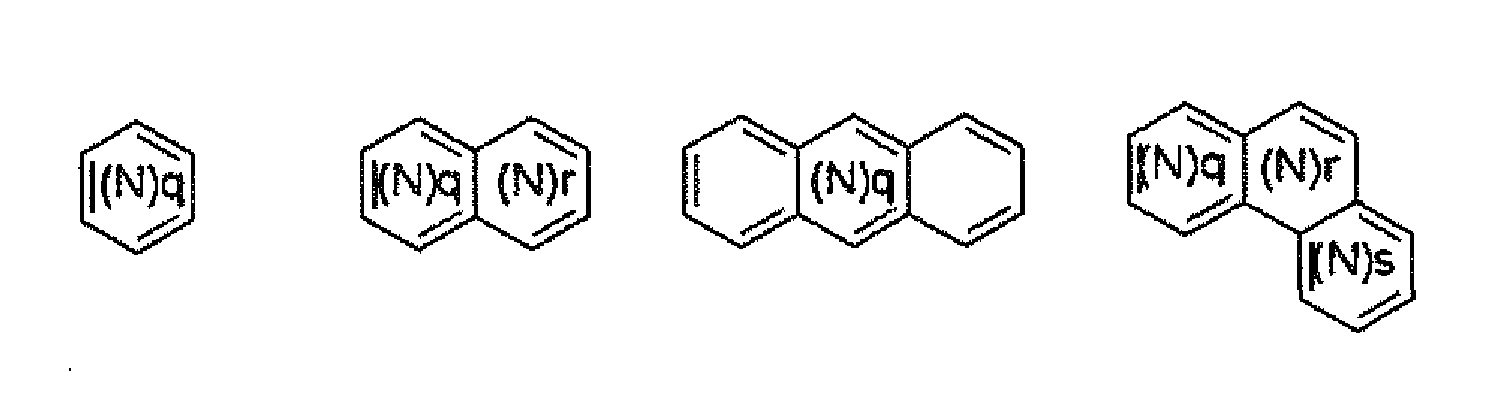

- The compound as set forth in claim 1, wherein Ar1 is a phenyl group.
- The compound as set forth in claim 1, wherein the compound that is represented by Formula 1 is selected from the compounds that are represented by the compounds described in the following Table:
[Table 1-1] Product 1-1-No structure compound 1-1-1 
compound 1-1-2 
compound 1-1-3 
compound 1-1-4 
compound 1-1-5 
compound 1-1-6 
compound 1-1-7 
compound 1-1-8 
compound 1-1-9 
compound 1-1-10 
compound 1-1-11 
compound 1-1-12 
compound 1-1-13 
compound 1-1-14 
[Table 1-2] Product 1-2-No structure compound 1-2-1 
compound 1-2-2 
compound 1-2-3 
compound 1-2-4 
compound 1-2-5 
compound 1-2-6 
compound 1-2-7 
compound 1-2-8 
compound 1-2-9 
compound 1-2-10 
compound 1-2-11 
compound 1-2-12 
compound 1-2-13 
Compound 1-2-14 
compound 1-2-15 
compound 1-2-16 
compound 1-2-17 
compound 1-2-16 
compound 1-2-17 
compound 1-2-18 
compound 1-2-19 
compound 1-2-20 
[Table 1-3] Product 1-3-No structure compound 1-3-1 
compound 1-3-2 
compound 1-3-3 
compound 1-3-4 
[Table 1-4] Product 1-4-No structure compound 1-4-1 
compound 1-4-2 
compound 1-4-3 
[Table 1-5] Product 1-5-No structure compound 1-5-1 
compound 1-5-2 
compound 1-5-3 
compound 1-5-4 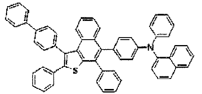
compound 1-5-5 
[Table 1-6] Product 1-6-No structure compound 1-6-1 
compound 1-6-2 
compound 1-6-3 
[Table 1-7] Product 1-7-No structure compound 1-7-1 
compound 1-7-2 
compound 1-7-3 
[Table 2-1] Product 2-1-No structure compound 2-1-1 
compound 2-1-2 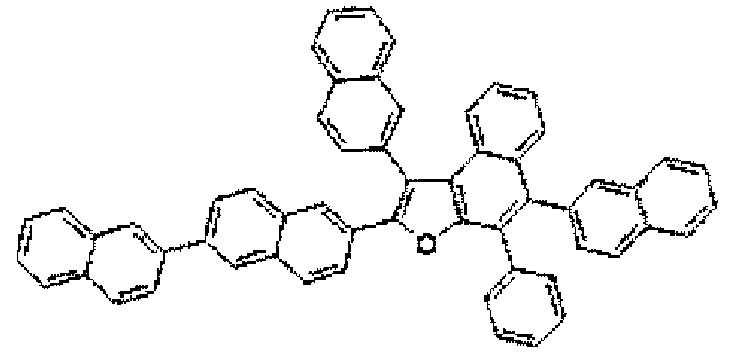
compound 2-1-3 
compound 2-1-4 
compound 2-1-5 
2-1-6 
[Table 3-1] Product 3-1-No. structure compound 3-1-1 
compound 3-1-2 
compound 3-1-3 
compound 3-1-4 
compound 3-1-5 
compound 3-1-6 
compound 3-1-7 
compound 3-1-8 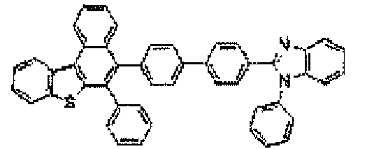
compound 3-1-9 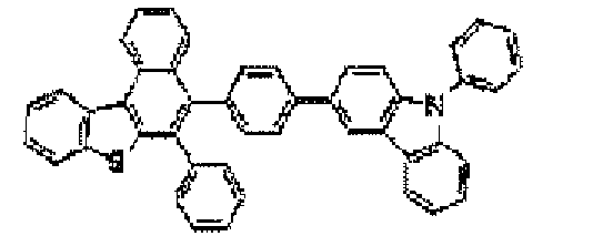
compound 3-1-10 
compound 3-1-11 
compound 3-1-12 
compound 3-1-13 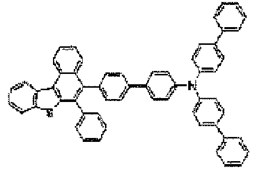
compound 3-1-14 
compound 3-1-15 
compound 3-1-16 
compound 3-1-17 
compound 3-1-18 
compound 3-1-19 
compound 3-1-20 
[Table 4-1] Product 4-1-No structure compound 4-1-1 
compound 4-1-2 
compound 4-1-3 
compound 4-1-4 
compound 4-1-5 
compound 4-1-6 
compound 4-1-7 
compound 4-1-8 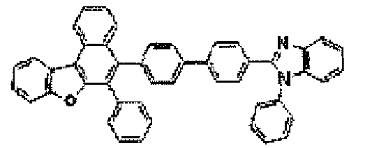
compound 4-1-9 
compound 4-1-10 
compound 4-1-11 
compound 4-1-12 
compound 4-1-13 
compound 4-1-14 
[Table 5-1] Product 5-1-No structure compound 5-1-1 
compound 5-1-2 
compound 5-1-3 
- An organic electronic device which includes a first electrode, a second electrode, and one or more organic material layers that are disposed between the first electrode and the second electrode, wherein one or more layers of the organic material layers include the compound according to any one of claims 1 to 10.
- The organic electronic device as set forth in claim 11, wherein the organic material layer includes a hole injection layer or a hole transport layer, and the hole injection layer or hole transport layer includes the compound of Formula 1.
- The organic light emitting device as set forth in claim 12, wherein the hole injection layer or hole transport layer further includes a dopant material.
- The organic electronic device as set forth in claim 11, wherein the organic material layer includes a light emitting layer, and the light emitting layer includes the compound of Formula 1.
- The organic light emitting device as set forth in claim 14, wherein the light emitting layer that includes the compound of Formula 1 further includes a fluorescent dopant material or phosphorescent dopant material.
- The organic electronic device as set forth in claim 11, wherein the organic material layer includes an electron injection layer or an electron transport, layer, and the electron injection layer or electron transport layer includes the compound of Formula 1.
- The organic light emitting device as set forth in claim 16, wherein the electron injection layer or electron transport layer further includes a dopant material.
- The organic electronic device as set forth in claim 11, wherein the organic electronic device is selected from the group consisting of an organic light emitting device, an organic solar cell, an organic photoconductor (OPC) drum and an organic transistor.
Applications Claiming Priority (2)
| Application Number | Priority Date | Filing Date | Title |
|---|---|---|---|
| KR20080093440 | 2008-09-23 | ||
| PCT/KR2009/005431 WO2010036027A2 (en) | 2008-09-23 | 2009-09-23 | Novel compound, method for preparing same and organic electronic device using same |
Publications (3)
| Publication Number | Publication Date |
|---|---|
| EP2332931A2 true EP2332931A2 (en) | 2011-06-15 |
| EP2332931A4 EP2332931A4 (en) | 2012-02-29 |
| EP2332931B1 EP2332931B1 (en) | 2015-04-22 |
Family
ID=42060273
Family Applications (1)
| Application Number | Title | Priority Date | Filing Date |
|---|---|---|---|
| EP20090816420 Active EP2332931B1 (en) | 2008-09-23 | 2009-09-23 | Novel compound, method for preparing same and organic electronic device using same |
Country Status (6)
| Country | Link |
|---|---|
| US (1) | US9028977B2 (en) |
| EP (1) | EP2332931B1 (en) |
| JP (2) | JP5484472B2 (en) |
| KR (1) | KR101262443B1 (en) |
| CN (2) | CN102224148B (en) |
| WO (1) | WO2010036027A2 (en) |
Cited By (8)
| Publication number | Priority date | Publication date | Assignee | Title |
|---|---|---|---|---|
| EP2436679A4 (en) * | 2009-05-29 | 2012-12-19 | Idemitsu Kosan Co | ANTHRACENE DERIVATIVE AND ORGANIC ELECTROLUMINESCENT ELEMENT USING THE SAME |
| EP2527334A4 (en) * | 2010-01-21 | 2013-10-16 | Idemitsu Kosan Co | AROMATIC AMINE DERIVATIVE, AND ORGANIC ELECTROLUMINESCENCE ELEMENT COMPRISING THE SAME |
| US8604224B2 (en) | 2010-12-28 | 2013-12-10 | Semiconductor Energy Laboratory Co., Ltd. | Benzo[b]naphtho[1,2-d]furan compound as light-emitting element material |
| WO2014030921A1 (en) * | 2012-08-21 | 2014-02-27 | Rohm And Haas Electronic Materials Korea Ltd. | Novel organic electroluminescence compounds and organic electroluminescence device containing the same |
| US8674117B2 (en) | 2010-12-28 | 2014-03-18 | Semiconductor Energy Laboratory Co., Ltd. | Organoboron compound and method for manufacturing the same |
| EP3048654A3 (en) * | 2015-01-20 | 2016-12-14 | Samsung Display Co., Ltd. | Organic light-emitting device |
| EP3904353A4 (en) * | 2018-12-27 | 2022-08-17 | LT Materials Co., Ltd. | POLYCYCLIC COMPOUND AND ORGANIC LIGHT EMITTING DEVICE THEREOF |
| US12089491B2 (en) | 2016-01-29 | 2024-09-10 | Semiconductor Energy Laboratory Co., Ltd. | Light-emitting element, light-emitting device, electronic device, and lighting device |
Families Citing this family (58)
| Publication number | Priority date | Publication date | Assignee | Title |
|---|---|---|---|---|
| JP5484472B2 (en) * | 2008-09-23 | 2014-05-07 | エルジー・ケム・リミテッド | NOVEL COMPOUND, PROCESS FOR PRODUCING THE SAME, AND ORGANIC ELECTRONIC DEVICE USING THE SAME |
| KR101427457B1 (en) * | 2009-02-27 | 2014-08-08 | 이 아이 듀폰 디 네모아 앤드 캄파니 | Deuterated compounds for electronic applications |
| US8759818B2 (en) | 2009-02-27 | 2014-06-24 | E I Du Pont De Nemours And Company | Deuterated compounds for electronic applications |
| JP5587023B2 (en) | 2010-04-22 | 2014-09-10 | キヤノン株式会社 | Novel naphthothiophene compound and organic light emitting device having the same |
| US8968887B2 (en) * | 2010-04-28 | 2015-03-03 | Universal Display Corporation | Triphenylene-benzofuran/benzothiophene/benzoselenophene compounds with substituents joining to form fused rings |
| KR101420318B1 (en) * | 2010-06-17 | 2014-07-16 | 이-레이 옵토일렉트로닉스 테크놀로지 컴퍼니 리미티드 | Compound for organic electroluminescent device and organic electroluminescent device having the same |
| WO2012070226A1 (en) * | 2010-11-22 | 2012-05-31 | 出光興産株式会社 | Oxygenated fused ring derivative and organic electroluminescence element containing the same |
| US20130264560A1 (en) * | 2010-12-20 | 2013-10-10 | E I Du Pont De Nemours And Company | Triazine derivatives for electronic applications |
| KR20130025190A (en) * | 2011-09-01 | 2013-03-11 | 롬엔드하스전자재료코리아유한회사 | Novel compounds for organic electronic material and organic electroluminescent device using the same |
| WO2013036043A2 (en) * | 2011-09-09 | 2013-03-14 | 주식회사 엘지화학 | Material for organic light-emitting device, and organic light-emitting device using same |
| CN103159745B (en) * | 2011-12-16 | 2016-01-20 | 昱镭光电科技股份有限公司 | Compound for organic electroluminescent device and organic electroluminescent device |
| WO2013096543A1 (en) * | 2011-12-20 | 2013-06-27 | E. I. Du Pont De Nemours And Company | Process and materials for making contained layers and devices made with same |
| CN103360322A (en) * | 2012-03-30 | 2013-10-23 | 海洋王照明科技股份有限公司 | Organic semiconductor material made of benzimidazole substituted pyrene as well as preparation method and applications thereof |
| KR101740486B1 (en) | 2012-07-25 | 2017-05-29 | 삼성디스플레이 주식회사 | Heteroring compound and organic light-emitting device including the same |
| US9312500B2 (en) | 2012-08-31 | 2016-04-12 | Idemitsu Kosan Co., Ltd. | Organic electroluminescence device |
| TW201418238A (en) * | 2012-08-31 | 2014-05-16 | Idemitsu Kosan Co | Organic electroluminescent element |
| CN110003199B (en) | 2012-09-12 | 2022-09-23 | 出光兴产株式会社 | Novel compound, material for organic electroluminescent element, and electronic device |
| KR102202171B1 (en) * | 2012-12-26 | 2021-01-12 | 이데미쓰 고산 가부시키가이샤 | Oxygen-containing fused ring amine compound, sulphur-containing fused ring amine compound, and organic electroluminescent element |
| EP2924029B1 (en) | 2013-03-15 | 2018-12-12 | Idemitsu Kosan Co., Ltd | Anthracene derivative and organic electroluminescence element using same |
| US9425408B2 (en) | 2013-03-22 | 2016-08-23 | Nitto Denko Corporation | Organic light emitting host materials |
| WO2014199637A1 (en) | 2013-06-11 | 2014-12-18 | 出光興産株式会社 | Material for organic electroluminescent elements, organic electroluminescent element using same, and electronic device |
| DE112014003458T5 (en) * | 2013-07-26 | 2016-04-07 | Semiconductor Energy Laboratory Co., Ltd. | Organic compound, light-emitting element, light-emitting device, electronic device and lighting device |
| CN103525400A (en) * | 2013-09-17 | 2014-01-22 | 吉林奥来德光电材料股份有限公司 | Styryl derivative organic electroluminescent material and preparation method thereof |
| CN104638105B (en) * | 2013-11-08 | 2018-01-23 | 北京鼎材科技有限公司 | A kind of OTFT and preparation method thereof |
| TWI583682B (en) * | 2013-12-16 | 2017-05-21 | 昆山維信諾顯示技術有限公司 | Benzothiophene derivatives and organic electroluminescent devices using the same |
| KR102203101B1 (en) * | 2014-04-18 | 2021-01-15 | 삼성디스플레이 주식회사 | Amine-based compounds and organic light-emitting device comprising the same |
| KR101763222B1 (en) | 2014-06-27 | 2017-07-31 | 희성소재 (주) | Hetero-cyclic compound and organic light emitting device using the same |
| CN107591496A (en) * | 2015-01-05 | 2018-01-16 | 北京鼎材科技有限公司 | Organic electroluminescence device and its compound |
| TWI723007B (en) * | 2015-02-18 | 2021-04-01 | 德商諾瓦發光二極體有限公司 | Semiconducting material and naphthofurane matrix compound for it |
| EP3274419B1 (en) * | 2015-03-25 | 2019-04-03 | Merck Patent GmbH | Materials for organic electroluminescent devices |
| KR101923171B1 (en) | 2015-05-27 | 2018-11-28 | 덕산네오룩스 주식회사 | Compound for organic electric element, organic electric element comprising the same and electronic device thereof |
| KR102399573B1 (en) * | 2015-08-04 | 2022-05-19 | 삼성디스플레이 주식회사 | Compound and Organic light emitting device comprising same |
| US10519166B2 (en) * | 2015-10-26 | 2019-12-31 | Lg Chem, Ltd. | Heterocyclic compound and organic light emitting device comprising the same |
| US9985579B2 (en) | 2016-04-12 | 2018-05-29 | Preformed Line Products Co. | Mounting assembly for mounting a solar panel |
| US12384796B2 (en) | 2016-06-03 | 2025-08-12 | Lg Chem, Ltd. | Electroactive compounds |
| KR101801003B1 (en) * | 2016-08-23 | 2017-11-24 | 주식회사 두산 | Organic compounds and organic electro luminescence device comprising the same |
| TWI909429B (en) | 2016-09-14 | 2025-12-21 | 日商半導體能源研究所股份有限公司 | Organic compound, light-emitting element, light-emitting device, electronic device, and lighting device |
| US10741769B2 (en) * | 2016-10-14 | 2020-08-11 | Semiconductor Energy Laboratory Co., Ltd. | Organic compound, light-emitting element, light-emitting device, electronic device, and lighting device |
| KR102701648B1 (en) | 2016-12-28 | 2024-09-03 | 가부시키가이샤 한도오따이 에네루기 켄큐쇼 | Organic compound, light-emitting element, light-emitting device, electronic device, display device, and lighting device |
| EP3583636B1 (en) * | 2017-02-20 | 2023-05-24 | Novaled GmbH | Electronic semiconducting device, method for preparing the electronic semiconducting device and compound |
| KR102414653B1 (en) * | 2017-09-29 | 2022-06-30 | 엘티소재주식회사 | Heterocyclic compound and organic light emitting device comprising the same |
| KR102855273B1 (en) | 2018-07-31 | 2025-09-05 | 가부시키가이샤 한도오따이 에네루기 켄큐쇼 | Organic compounds, light-emitting elements, light-emitting devices, electronic devices, and lighting devices |
| KR102887183B1 (en) * | 2019-03-05 | 2025-11-18 | 삼성디스플레이 주식회사 | Organic electroluminescence device and polycyclic compound for organic electroluminescence device |
| KR20210008812A (en) * | 2019-07-15 | 2021-01-25 | 롬엔드하스전자재료코리아유한회사 | A plurality of host materials and organic electroluminescent device comprising the same |
| CN114514225A (en) * | 2019-07-31 | 2022-05-17 | 杜邦电子公司 | Electroactive compounds |
| KR102484481B1 (en) * | 2019-10-31 | 2023-01-05 | 주식회사 동진쎄미켐 | New organic compound for capping layer and Organic light emitting diode comprising to the same |
| KR102603291B1 (en) | 2020-01-30 | 2023-11-15 | 삼성에스디아이 주식회사 | Compound for organic optoelectronic device, composition for organic optoelectronic device, organic optoelectronic device and display device |
| KR20210150996A (en) * | 2020-06-04 | 2021-12-13 | 주식회사 동진쎄미켐 | New compound for capping layer and Organic light emitting diode comprising to the same |
| CN113972332B (en) * | 2021-11-05 | 2024-05-24 | 陕西莱特光电材料股份有限公司 | Organic electroluminescent device and electronic device including the same |
| CN114335399B (en) * | 2021-12-03 | 2024-04-09 | 陕西莱特迈思光电材料有限公司 | Organic electroluminescent device and electronic device including the same |
| CN116813606B (en) * | 2022-03-15 | 2026-03-06 | 江苏三月科技股份有限公司 | A carbazole-based organic compound containing a naphthanoheterocyclic group and an organic electroluminescent device comprising the same. |
| KR102814310B1 (en) * | 2022-06-29 | 2025-05-29 | 주식회사 엘지화학 | Compound and organic light emitting device comprising same |
| KR20240002594A (en) * | 2022-06-29 | 2024-01-05 | 주식회사 엘지화학 | Compound and organic light emitting device comprising same |
| KR102749880B1 (en) * | 2022-06-29 | 2025-01-03 | 주식회사 엘지화학 | Compound and organic light emitting device comprising same |
| JP7803478B2 (en) * | 2022-07-07 | 2026-01-21 | エルジー・ケム・リミテッド | Compound and organic light-emitting device containing the same |
| CN116283814B (en) * | 2022-12-27 | 2026-03-10 | 长春海谱润斯科技股份有限公司 | Heterocyclic compound and organic electroluminescent device thereof |
| KR20250095557A (en) * | 2023-12-19 | 2025-06-26 | 주식회사 엘지화학 | Compound and organic light emitting device comprising same |
| WO2025135823A1 (en) * | 2023-12-19 | 2025-06-26 | 주식회사 엘지화학 | Compound and organic light-emitting device comprising same |
Citations (4)
| Publication number | Priority date | Publication date | Assignee | Title |
|---|---|---|---|---|
| EP1593675A1 (en) | 2003-02-14 | 2005-11-09 | Idemitsu Kosan Co., Ltd. | Hetero-polycyclic compounds, and coloring matters, pigments, dyes, color-changing material compositions, and color-changing films, made by using the compounds |
| WO2006128800A1 (en) | 2005-05-30 | 2006-12-07 | Ciba Specialty Chemicals Holding Inc. | Electroluminescent device |
| US20070063190A1 (en) | 2003-10-06 | 2007-03-22 | Sumitomo Chemical Company, Limited | Aromatic compound |
| EP1962354A1 (en) | 2005-12-15 | 2008-08-27 | Idemitsu Kosan Co., Ltd. | Organic electroluminescence element material and organic electroluminescence element using same |
Family Cites Families (19)
| Publication number | Priority date | Publication date | Assignee | Title |
|---|---|---|---|---|
| US5077142A (en) * | 1989-04-20 | 1991-12-31 | Ricoh Company, Ltd. | Electroluminescent devices |
| JPH0534904A (en) * | 1990-07-24 | 1993-02-12 | Konica Corp | Photosensitive composition |
| JPH05197140A (en) * | 1992-01-22 | 1993-08-06 | Konica Corp | Free radical generating agent and photosensitive composition |
| US5543631A (en) * | 1993-06-17 | 1996-08-06 | Weinberger; Lester | Hybrid organic-inorganic bistable nonlinear optical gate |
| JPH09210472A (en) | 1996-01-31 | 1997-08-12 | Canon Inc | Heat collecting panel and passive solar system |
| JP3556391B2 (en) * | 1996-05-09 | 2004-08-18 | 三菱製紙株式会社 | Organic photoconductive material and electrophotographic photoreceptor using the same |
| JP3589796B2 (en) * | 1996-07-10 | 2004-11-17 | 京セラミタ株式会社 | Electrophotographic photoreceptor |
| JP3736252B2 (en) * | 2000-01-26 | 2006-01-18 | 凸版印刷株式会社 | Organic EL device using 1,2-dithiophene-yl-ethylene derivative |
| TWI314947B (en) * | 2002-04-24 | 2009-09-21 | Eastman Kodak Compan | Organic light emitting diode devices with improved operational stability |
| JP3969300B2 (en) * | 2002-12-24 | 2007-09-05 | 東洋インキ製造株式会社 | Composition for organic electroluminescence device and organic electroluminescence device using the same |
| JP5034157B2 (en) * | 2003-10-06 | 2012-09-26 | 住友化学株式会社 | Aromatic compounds |
| JP4158044B2 (en) | 2003-10-09 | 2008-10-01 | 大塚化学株式会社 | Penicillin crystals and production method thereof |
| KR20080031872A (en) * | 2005-06-24 | 2008-04-11 | 이데미쓰 고산 가부시키가이샤 | Benzothiophene Derivatives and Organic Electroluminescent Devices Using the Same |
| US20080166594A1 (en) * | 2005-06-24 | 2008-07-10 | Idemitsu Kosan Co., Ltd. | Benzothiophene derivative and organic electroluminescence device making use of the same |
| JP5145544B2 (en) * | 2005-11-02 | 2013-02-20 | 和歌山県 | Benzodithiophene derivative and organic electroluminescence device using the benzodithiophene derivative as a light emitting layer |
| US7996962B2 (en) * | 2006-03-15 | 2011-08-16 | Smart Tie, Llc | Adjustable length rope clip system |
| DE102006031990A1 (en) * | 2006-07-11 | 2008-01-17 | Merck Patent Gmbh | New materials for organic electroluminescent devices |
| JP2009049090A (en) * | 2007-08-16 | 2009-03-05 | Mitsui Chemicals Inc | Organic transistor |
| JP5484472B2 (en) * | 2008-09-23 | 2014-05-07 | エルジー・ケム・リミテッド | NOVEL COMPOUND, PROCESS FOR PRODUCING THE SAME, AND ORGANIC ELECTRONIC DEVICE USING THE SAME |
-
2009
- 2009-09-23 JP JP2011528932A patent/JP5484472B2/en active Active
- 2009-09-23 CN CN200980146553.5A patent/CN102224148B/en active Active
- 2009-09-23 US US13/120,380 patent/US9028977B2/en active Active
- 2009-09-23 EP EP20090816420 patent/EP2332931B1/en active Active
- 2009-09-23 KR KR1020090090239A patent/KR101262443B1/en active Active
- 2009-09-23 WO PCT/KR2009/005431 patent/WO2010036027A2/en not_active Ceased
- 2009-09-23 CN CN201410166657.5A patent/CN104045623B/en active Active
-
2013
- 2013-12-09 JP JP2013253992A patent/JP2014111598A/en active Pending
Patent Citations (4)
| Publication number | Priority date | Publication date | Assignee | Title |
|---|---|---|---|---|
| EP1593675A1 (en) | 2003-02-14 | 2005-11-09 | Idemitsu Kosan Co., Ltd. | Hetero-polycyclic compounds, and coloring matters, pigments, dyes, color-changing material compositions, and color-changing films, made by using the compounds |
| US20070063190A1 (en) | 2003-10-06 | 2007-03-22 | Sumitomo Chemical Company, Limited | Aromatic compound |
| WO2006128800A1 (en) | 2005-05-30 | 2006-12-07 | Ciba Specialty Chemicals Holding Inc. | Electroluminescent device |
| EP1962354A1 (en) | 2005-12-15 | 2008-08-27 | Idemitsu Kosan Co., Ltd. | Organic electroluminescence element material and organic electroluminescence element using same |
Non-Patent Citations (2)
| Title |
|---|
| See also references of WO2010036027A2 |
| YAO T. ET AL: "Synthesis of polycyclic aromatics and heteroaromatics via electrophilic cyclization", THE JOURNAL OF ORGANIC CHEMISTRY, vol. 70, no. 9, 1 January 2005 (2005-01-01), pages 3511 - 3517, XP002493803 |
Cited By (13)
| Publication number | Priority date | Publication date | Assignee | Title |
|---|---|---|---|---|
| US8866135B2 (en) | 2009-05-29 | 2014-10-21 | Idemitsu Kosan Co., Ltd. | Anthracene derivative and organic electroluminescent element using the same |
| US8629430B2 (en) | 2009-05-29 | 2014-01-14 | Idemitsu Kosan Co., Ltd. | Anthracene derivative and organic electroluminescent element using the same |
| EP2436679A4 (en) * | 2009-05-29 | 2012-12-19 | Idemitsu Kosan Co | ANTHRACENE DERIVATIVE AND ORGANIC ELECTROLUMINESCENT ELEMENT USING THE SAME |
| US9147847B2 (en) | 2009-05-29 | 2015-09-29 | Idemitsu Kosan Co., Ltd. | Anthracene derivative and organic electroluminescent element using the same |
| US9373792B2 (en) | 2009-05-29 | 2016-06-21 | Idemitsu Kosan Co., Ltd. | Anthracene derivative and organic electroluminescent element using the same |
| EP2527334A4 (en) * | 2010-01-21 | 2013-10-16 | Idemitsu Kosan Co | AROMATIC AMINE DERIVATIVE, AND ORGANIC ELECTROLUMINESCENCE ELEMENT COMPRISING THE SAME |
| US8604224B2 (en) | 2010-12-28 | 2013-12-10 | Semiconductor Energy Laboratory Co., Ltd. | Benzo[b]naphtho[1,2-d]furan compound as light-emitting element material |
| US8674117B2 (en) | 2010-12-28 | 2014-03-18 | Semiconductor Energy Laboratory Co., Ltd. | Organoboron compound and method for manufacturing the same |
| WO2014030921A1 (en) * | 2012-08-21 | 2014-02-27 | Rohm And Haas Electronic Materials Korea Ltd. | Novel organic electroluminescence compounds and organic electroluminescence device containing the same |
| EP3048654A3 (en) * | 2015-01-20 | 2016-12-14 | Samsung Display Co., Ltd. | Organic light-emitting device |
| US12089491B2 (en) | 2016-01-29 | 2024-09-10 | Semiconductor Energy Laboratory Co., Ltd. | Light-emitting element, light-emitting device, electronic device, and lighting device |
| DE112017000558B4 (en) | 2016-01-29 | 2025-04-30 | Semiconductor Energy Laboratory Co., Ltd. | Hole transport material, organic compound, light-emitting element and light-emitting device |
| EP3904353A4 (en) * | 2018-12-27 | 2022-08-17 | LT Materials Co., Ltd. | POLYCYCLIC COMPOUND AND ORGANIC LIGHT EMITTING DEVICE THEREOF |
Also Published As
| Publication number | Publication date |
|---|---|
| CN104045623B (en) | 2017-05-24 |
| JP2014111598A (en) | 2014-06-19 |
| KR101262443B1 (en) | 2013-05-08 |
| KR20100034719A (en) | 2010-04-01 |
| EP2332931A4 (en) | 2012-02-29 |
| WO2010036027A3 (en) | 2010-06-24 |
| US9028977B2 (en) | 2015-05-12 |
| CN104045623A (en) | 2014-09-17 |
| JP5484472B2 (en) | 2014-05-07 |
| EP2332931B1 (en) | 2015-04-22 |
| CN102224148A (en) | 2011-10-19 |
| US20110168992A1 (en) | 2011-07-14 |
| WO2010036027A2 (en) | 2010-04-01 |
| CN102224148B (en) | 2015-07-15 |
| JP2012503027A (en) | 2012-02-02 |
Similar Documents
| Publication | Publication Date | Title |
|---|---|---|
| EP2332931B1 (en) | Novel compound, method for preparing same and organic electronic device using same | |
| EP2570412B1 (en) | Novel nitrogen-containing heterocyclic compound and organic electronic device using the same | |
| US8344368B2 (en) | Fused cyclic compound and organic electronic device | |
| EP2749560B1 (en) | Novel nitrogen-containing heterocyclic compounds and organic electronic device using same | |
| US8318325B2 (en) | Anthracene derivatives and organic electronic device using same | |
| KR101317501B1 (en) | Novel compound, derivatives thereof and organic electronic device using the same | |
| EP3032606B1 (en) | Organic optoelectric device and display device | |
| JP5902655B2 (en) | Organic electronic device and its compound, terminal | |
| TWI664183B (en) | Compound having spiro structure and organic light emitting device comprising the same | |
| EP3260438B1 (en) | Double-spiro type compound and organic light-emitting device containing same | |
| JP6058818B2 (en) | Heterocyclic compound and organic light emitting device using the same | |
| KR20170037522A (en) | Amine-based compound and organic light emitting device comprising the same | |
| EP3330249B1 (en) | Amine-based compound and organic light emitting device comprising same | |
| EP3263555B1 (en) | Hetero ring compound and organic luminescent element comprising same | |
| EP3321246B1 (en) | Double spiro compound and organic light-emitting element comprising same | |
| WO2018155826A1 (en) | Novel compound and organic light emitting element using same | |
| CN116326250A (en) | organic light emitting device | |
| KR101578475B1 (en) | Compound Containing Dibenzothiophene, Arylamine Derivatives And Organic Electronic Element Using The Same, Terminal Thereof | |
| EP2390249B1 (en) | Novel cycloalkene derivatives and organic electronic devices using the same | |
| KR101405736B1 (en) | Novel anthracene derivatives and organic electronic devices using the same | |
| KR102103503B1 (en) | Novel compound and organic light emitting device comprising the same | |
| TW202421760A (en) | Organic light emitting device, and composition for formation of organic material layer | |
| CN118496069A (en) | Organic compound based on aryl bonded through sixth main group atom at periphery of central benzene ring, and preparation method and application thereof | |
| KR20130098260A (en) | New anthracene derivatives and organic electronic device using the same |
Legal Events
| Date | Code | Title | Description |
|---|---|---|---|
| PUAI | Public reference made under article 153(3) epc to a published international application that has entered the european phase |
Free format text: ORIGINAL CODE: 0009012 |
|
| 17P | Request for examination filed |
Effective date: 20110323 |
|
| AK | Designated contracting states |
Kind code of ref document: A2 Designated state(s): AT BE BG CH CY CZ DE DK EE ES FI FR GB GR HR HU IE IS IT LI LT LU LV MC MK MT NL NO PL PT RO SE SI SK SM TR |
|
| AX | Request for extension of the european patent |
Extension state: AL BA RS |
|
| DAX | Request for extension of the european patent (deleted) | ||
| A4 | Supplementary search report drawn up and despatched |
Effective date: 20120126 |
|
| RIC1 | Information provided on ipc code assigned before grant |
Ipc: C07D 333/74 20060101AFI20120120BHEP |
|
| 17Q | First examination report despatched |
Effective date: 20121008 |
|
| TPAC | Observations filed by third parties |
Free format text: ORIGINAL CODE: EPIDOSNTIPA |
|
| GRAP | Despatch of communication of intention to grant a patent |
Free format text: ORIGINAL CODE: EPIDOSNIGR1 |
|
| INTG | Intention to grant announced |
Effective date: 20150120 |
|
| GRAS | Grant fee paid |
Free format text: ORIGINAL CODE: EPIDOSNIGR3 |
|
| GRAA | (expected) grant |
Free format text: ORIGINAL CODE: 0009210 |
|
| AK | Designated contracting states |
Kind code of ref document: B1 Designated state(s): AT BE BG CH CY CZ DE DK EE ES FI FR GB GR HR HU IE IS IT LI LT LU LV MC MK MT NL NO PL PT RO SE SI SK SM TR |
|
| REG | Reference to a national code |
Ref country code: GB Ref legal event code: FG4D |
|
| REG | Reference to a national code |
Ref country code: CH Ref legal event code: EP |
|
| REG | Reference to a national code |
Ref country code: AT Ref legal event code: REF Ref document number: 723144 Country of ref document: AT Kind code of ref document: T Effective date: 20150515 |
|
| REG | Reference to a national code |
Ref country code: IE Ref legal event code: FG4D |
|
| REG | Reference to a national code |
Ref country code: DE Ref legal event code: R096 Ref document number: 602009030868 Country of ref document: DE Effective date: 20150603 |
|
| REG | Reference to a national code |
Ref country code: NL Ref legal event code: VDEP Effective date: 20150422 |
|
| REG | Reference to a national code |
Ref country code: AT Ref legal event code: MK05 Ref document number: 723144 Country of ref document: AT Kind code of ref document: T Effective date: 20150422 |
|
| REG | Reference to a national code |
Ref country code: LT Ref legal event code: MG4D |
|
| PG25 | Lapsed in a contracting state [announced via postgrant information from national office to epo] |
Ref country code: NL Free format text: LAPSE BECAUSE OF FAILURE TO SUBMIT A TRANSLATION OF THE DESCRIPTION OR TO PAY THE FEE WITHIN THE PRESCRIBED TIME-LIMIT Effective date: 20150422 |
|
| PG25 | Lapsed in a contracting state [announced via postgrant information from national office to epo] |
Ref country code: NO Free format text: LAPSE BECAUSE OF FAILURE TO SUBMIT A TRANSLATION OF THE DESCRIPTION OR TO PAY THE FEE WITHIN THE PRESCRIBED TIME-LIMIT Effective date: 20150722 Ref country code: HR Free format text: LAPSE BECAUSE OF FAILURE TO SUBMIT A TRANSLATION OF THE DESCRIPTION OR TO PAY THE FEE WITHIN THE PRESCRIBED TIME-LIMIT Effective date: 20150422 Ref country code: LT Free format text: LAPSE BECAUSE OF FAILURE TO SUBMIT A TRANSLATION OF THE DESCRIPTION OR TO PAY THE FEE WITHIN THE PRESCRIBED TIME-LIMIT Effective date: 20150422 Ref country code: PT Free format text: LAPSE BECAUSE OF FAILURE TO SUBMIT A TRANSLATION OF THE DESCRIPTION OR TO PAY THE FEE WITHIN THE PRESCRIBED TIME-LIMIT Effective date: 20150824 Ref country code: FI Free format text: LAPSE BECAUSE OF FAILURE TO SUBMIT A TRANSLATION OF THE DESCRIPTION OR TO PAY THE FEE WITHIN THE PRESCRIBED TIME-LIMIT Effective date: 20150422 Ref country code: ES Free format text: LAPSE BECAUSE OF FAILURE TO SUBMIT A TRANSLATION OF THE DESCRIPTION OR TO PAY THE FEE WITHIN THE PRESCRIBED TIME-LIMIT Effective date: 20150422 |
|
| PG25 | Lapsed in a contracting state [announced via postgrant information from national office to epo] |
Ref country code: LV Free format text: LAPSE BECAUSE OF FAILURE TO SUBMIT A TRANSLATION OF THE DESCRIPTION OR TO PAY THE FEE WITHIN THE PRESCRIBED TIME-LIMIT Effective date: 20150422 Ref country code: IS Free format text: LAPSE BECAUSE OF FAILURE TO SUBMIT A TRANSLATION OF THE DESCRIPTION OR TO PAY THE FEE WITHIN THE PRESCRIBED TIME-LIMIT Effective date: 20150822 Ref country code: AT Free format text: LAPSE BECAUSE OF FAILURE TO SUBMIT A TRANSLATION OF THE DESCRIPTION OR TO PAY THE FEE WITHIN THE PRESCRIBED TIME-LIMIT Effective date: 20150422 Ref country code: GR Free format text: LAPSE BECAUSE OF FAILURE TO SUBMIT A TRANSLATION OF THE DESCRIPTION OR TO PAY THE FEE WITHIN THE PRESCRIBED TIME-LIMIT Effective date: 20150723 |
|
| REG | Reference to a national code |
Ref country code: DE Ref legal event code: R097 Ref document number: 602009030868 Country of ref document: DE |
|
| PG25 | Lapsed in a contracting state [announced via postgrant information from national office to epo] |
Ref country code: DK Free format text: LAPSE BECAUSE OF FAILURE TO SUBMIT A TRANSLATION OF THE DESCRIPTION OR TO PAY THE FEE WITHIN THE PRESCRIBED TIME-LIMIT Effective date: 20150422 Ref country code: EE Free format text: LAPSE BECAUSE OF FAILURE TO SUBMIT A TRANSLATION OF THE DESCRIPTION OR TO PAY THE FEE WITHIN THE PRESCRIBED TIME-LIMIT Effective date: 20150422 |
|
| PLBE | No opposition filed within time limit |
Free format text: ORIGINAL CODE: 0009261 |
|
| STAA | Information on the status of an ep patent application or granted ep patent |
Free format text: STATUS: NO OPPOSITION FILED WITHIN TIME LIMIT |
|
| PG25 | Lapsed in a contracting state [announced via postgrant information from national office to epo] |
Ref country code: RO Free format text: LAPSE BECAUSE OF NON-PAYMENT OF DUE FEES Effective date: 20150422 Ref country code: CZ Free format text: LAPSE BECAUSE OF FAILURE TO SUBMIT A TRANSLATION OF THE DESCRIPTION OR TO PAY THE FEE WITHIN THE PRESCRIBED TIME-LIMIT Effective date: 20150422 Ref country code: SK Free format text: LAPSE BECAUSE OF FAILURE TO SUBMIT A TRANSLATION OF THE DESCRIPTION OR TO PAY THE FEE WITHIN THE PRESCRIBED TIME-LIMIT Effective date: 20150422 Ref country code: PL Free format text: LAPSE BECAUSE OF FAILURE TO SUBMIT A TRANSLATION OF THE DESCRIPTION OR TO PAY THE FEE WITHIN THE PRESCRIBED TIME-LIMIT Effective date: 20150422 |
|
| 26N | No opposition filed |
Effective date: 20160125 |
|
| PG25 | Lapsed in a contracting state [announced via postgrant information from national office to epo] |
Ref country code: MC Free format text: LAPSE BECAUSE OF FAILURE TO SUBMIT A TRANSLATION OF THE DESCRIPTION OR TO PAY THE FEE WITHIN THE PRESCRIBED TIME-LIMIT Effective date: 20150422 Ref country code: LU Free format text: LAPSE BECAUSE OF FAILURE TO SUBMIT A TRANSLATION OF THE DESCRIPTION OR TO PAY THE FEE WITHIN THE PRESCRIBED TIME-LIMIT Effective date: 20150923 Ref country code: IT Free format text: LAPSE BECAUSE OF FAILURE TO SUBMIT A TRANSLATION OF THE DESCRIPTION OR TO PAY THE FEE WITHIN THE PRESCRIBED TIME-LIMIT Effective date: 20150422 |
|
| REG | Reference to a national code |
Ref country code: CH Ref legal event code: PL |
|
| PG25 | Lapsed in a contracting state [announced via postgrant information from national office to epo] |
Ref country code: SI Free format text: LAPSE BECAUSE OF FAILURE TO SUBMIT A TRANSLATION OF THE DESCRIPTION OR TO PAY THE FEE WITHIN THE PRESCRIBED TIME-LIMIT Effective date: 20150422 |
|
| REG | Reference to a national code |
Ref country code: IE Ref legal event code: MM4A |
|
| PG25 | Lapsed in a contracting state [announced via postgrant information from national office to epo] |
Ref country code: IE Free format text: LAPSE BECAUSE OF NON-PAYMENT OF DUE FEES Effective date: 20150923 Ref country code: CH Free format text: LAPSE BECAUSE OF NON-PAYMENT OF DUE FEES Effective date: 20150930 Ref country code: LI Free format text: LAPSE BECAUSE OF NON-PAYMENT OF DUE FEES Effective date: 20150930 |
|
| REG | Reference to a national code |
Ref country code: FR Ref legal event code: PLFP Year of fee payment: 8 |
|
| PG25 | Lapsed in a contracting state [announced via postgrant information from national office to epo] |
Ref country code: BE Free format text: LAPSE BECAUSE OF FAILURE TO SUBMIT A TRANSLATION OF THE DESCRIPTION OR TO PAY THE FEE WITHIN THE PRESCRIBED TIME-LIMIT Effective date: 20150422 |
|
| PG25 | Lapsed in a contracting state [announced via postgrant information from national office to epo] |
Ref country code: MT Free format text: LAPSE BECAUSE OF FAILURE TO SUBMIT A TRANSLATION OF THE DESCRIPTION OR TO PAY THE FEE WITHIN THE PRESCRIBED TIME-LIMIT Effective date: 20150422 |
|
| PG25 | Lapsed in a contracting state [announced via postgrant information from national office to epo] |
Ref country code: BG Free format text: LAPSE BECAUSE OF FAILURE TO SUBMIT A TRANSLATION OF THE DESCRIPTION OR TO PAY THE FEE WITHIN THE PRESCRIBED TIME-LIMIT Effective date: 20150422 Ref country code: SM Free format text: LAPSE BECAUSE OF FAILURE TO SUBMIT A TRANSLATION OF THE DESCRIPTION OR TO PAY THE FEE WITHIN THE PRESCRIBED TIME-LIMIT Effective date: 20150422 Ref country code: HU Free format text: LAPSE BECAUSE OF FAILURE TO SUBMIT A TRANSLATION OF THE DESCRIPTION OR TO PAY THE FEE WITHIN THE PRESCRIBED TIME-LIMIT; INVALID AB INITIO Effective date: 20090923 |
|
| PG25 | Lapsed in a contracting state [announced via postgrant information from national office to epo] |
Ref country code: CY Free format text: LAPSE BECAUSE OF FAILURE TO SUBMIT A TRANSLATION OF THE DESCRIPTION OR TO PAY THE FEE WITHIN THE PRESCRIBED TIME-LIMIT Effective date: 20150422 Ref country code: SE Free format text: LAPSE BECAUSE OF FAILURE TO SUBMIT A TRANSLATION OF THE DESCRIPTION OR TO PAY THE FEE WITHIN THE PRESCRIBED TIME-LIMIT Effective date: 20150422 |
|
| REG | Reference to a national code |
Ref country code: FR Ref legal event code: PLFP Year of fee payment: 9 |
|
| PG25 | Lapsed in a contracting state [announced via postgrant information from national office to epo] |
Ref country code: TR Free format text: LAPSE BECAUSE OF FAILURE TO SUBMIT A TRANSLATION OF THE DESCRIPTION OR TO PAY THE FEE WITHIN THE PRESCRIBED TIME-LIMIT Effective date: 20150422 |
|
| PG25 | Lapsed in a contracting state [announced via postgrant information from national office to epo] |
Ref country code: MK Free format text: LAPSE BECAUSE OF FAILURE TO SUBMIT A TRANSLATION OF THE DESCRIPTION OR TO PAY THE FEE WITHIN THE PRESCRIBED TIME-LIMIT Effective date: 20150422 |
|
| REG | Reference to a national code |
Ref country code: FR Ref legal event code: PLFP Year of fee payment: 10 |
|
| PGFP | Annual fee paid to national office [announced via postgrant information from national office to epo] |
Ref country code: DE Payment date: 20250820 Year of fee payment: 17 |
|
| PGFP | Annual fee paid to national office [announced via postgrant information from national office to epo] |
Ref country code: GB Payment date: 20250820 Year of fee payment: 17 |
|
| PGFP | Annual fee paid to national office [announced via postgrant information from national office to epo] |
Ref country code: FR Payment date: 20250821 Year of fee payment: 17 |