EP2332890A1 - Method for cutting a brittle material - Google Patents
Method for cutting a brittle material Download PDFInfo
- Publication number
- EP2332890A1 EP2332890A1 EP10190949A EP10190949A EP2332890A1 EP 2332890 A1 EP2332890 A1 EP 2332890A1 EP 10190949 A EP10190949 A EP 10190949A EP 10190949 A EP10190949 A EP 10190949A EP 2332890 A1 EP2332890 A1 EP 2332890A1
- Authority
- EP
- European Patent Office
- Prior art keywords
- brittle material
- nozzle
- stream
- glass
- ribbon
- Prior art date
- Legal status (The legal status is an assumption and is not a legal conclusion. Google has not performed a legal analysis and makes no representation as to the accuracy of the status listed.)
- Granted
Links
Images


Classifications
-
- C—CHEMISTRY; METALLURGY
- C03—GLASS; MINERAL OR SLAG WOOL
- C03B—MANUFACTURE, SHAPING, OR SUPPLEMENTARY PROCESSES
- C03B33/00—Severing cooled glass
- C03B33/02—Cutting or splitting sheet glass or ribbons; Apparatus or machines therefor
- C03B33/023—Cutting or splitting sheet glass or ribbons; Apparatus or machines therefor the sheet or ribbon being in a horizontal position
- C03B33/033—Apparatus for opening score lines in glass sheets
-
- C—CHEMISTRY; METALLURGY
- C03—GLASS; MINERAL OR SLAG WOOL
- C03B—MANUFACTURE, SHAPING, OR SUPPLEMENTARY PROCESSES
- C03B33/00—Severing cooled glass
- C03B33/02—Cutting or splitting sheet glass or ribbons; Apparatus or machines therefor
- C03B33/0215—Cutting or splitting sheet glass or ribbons; Apparatus or machines therefor the ribbon being in a substantially vertical plane
-
- B—PERFORMING OPERATIONS; TRANSPORTING
- B23—MACHINE TOOLS; METAL-WORKING NOT OTHERWISE PROVIDED FOR
- B23K—SOLDERING OR UNSOLDERING; WELDING; CLADDING OR PLATING BY SOLDERING OR WELDING; CUTTING BY APPLYING HEAT LOCALLY, e.g. FLAME CUTTING; WORKING BY LASER BEAM
- B23K26/00—Working by laser beam, e.g. welding, cutting or boring
- B23K26/14—Working by laser beam, e.g. welding, cutting or boring using a fluid stream, e.g. a jet of gas, in conjunction with the laser beam; Nozzles therefor
- B23K26/146—Working by laser beam, e.g. welding, cutting or boring using a fluid stream, e.g. a jet of gas, in conjunction with the laser beam; Nozzles therefor the fluid stream containing a liquid
-
- B—PERFORMING OPERATIONS; TRANSPORTING
- B23—MACHINE TOOLS; METAL-WORKING NOT OTHERWISE PROVIDED FOR
- B23K—SOLDERING OR UNSOLDERING; WELDING; CLADDING OR PLATING BY SOLDERING OR WELDING; CUTTING BY APPLYING HEAT LOCALLY, e.g. FLAME CUTTING; WORKING BY LASER BEAM
- B23K26/00—Working by laser beam, e.g. welding, cutting or boring
- B23K26/36—Removing material
- B23K26/38—Removing material by boring or cutting
-
- B—PERFORMING OPERATIONS; TRANSPORTING
- B23—MACHINE TOOLS; METAL-WORKING NOT OTHERWISE PROVIDED FOR
- B23K—SOLDERING OR UNSOLDERING; WELDING; CLADDING OR PLATING BY SOLDERING OR WELDING; CUTTING BY APPLYING HEAT LOCALLY, e.g. FLAME CUTTING; WORKING BY LASER BEAM
- B23K26/00—Working by laser beam, e.g. welding, cutting or boring
- B23K26/36—Removing material
- B23K26/40—Removing material taking account of the properties of the material involved
-
- B—PERFORMING OPERATIONS; TRANSPORTING
- B23—MACHINE TOOLS; METAL-WORKING NOT OTHERWISE PROVIDED FOR
- B23K—SOLDERING OR UNSOLDERING; WELDING; CLADDING OR PLATING BY SOLDERING OR WELDING; CUTTING BY APPLYING HEAT LOCALLY, e.g. FLAME CUTTING; WORKING BY LASER BEAM
- B23K26/00—Working by laser beam, e.g. welding, cutting or boring
- B23K26/70—Auxiliary operations or equipment
- B23K26/702—Auxiliary equipment
- B23K26/703—Cooling arrangements
-
- B—PERFORMING OPERATIONS; TRANSPORTING
- B23—MACHINE TOOLS; METAL-WORKING NOT OTHERWISE PROVIDED FOR
- B23K—SOLDERING OR UNSOLDERING; WELDING; CLADDING OR PLATING BY SOLDERING OR WELDING; CUTTING BY APPLYING HEAT LOCALLY, e.g. FLAME CUTTING; WORKING BY LASER BEAM
- B23K37/00—Auxiliary devices or processes, not specially adapted for a procedure covered by only one of the other main groups of this subclass
- B23K37/003—Cooling means for welding or cutting
-
- C—CHEMISTRY; METALLURGY
- C03—GLASS; MINERAL OR SLAG WOOL
- C03B—MANUFACTURE, SHAPING, OR SUPPLEMENTARY PROCESSES
- C03B33/00—Severing cooled glass
- C03B33/02—Cutting or splitting sheet glass or ribbons; Apparatus or machines therefor
-
- C—CHEMISTRY; METALLURGY
- C03—GLASS; MINERAL OR SLAG WOOL
- C03B—MANUFACTURE, SHAPING, OR SUPPLEMENTARY PROCESSES
- C03B33/00—Severing cooled glass
- C03B33/09—Severing cooled glass by thermal shock
-
- C—CHEMISTRY; METALLURGY
- C03—GLASS; MINERAL OR SLAG WOOL
- C03B—MANUFACTURE, SHAPING, OR SUPPLEMENTARY PROCESSES
- C03B33/00—Severing cooled glass
- C03B33/09—Severing cooled glass by thermal shock
- C03B33/091—Severing cooled glass by thermal shock using at least one focussed radiation beam, e.g. laser beam
-
- B—PERFORMING OPERATIONS; TRANSPORTING
- B23—MACHINE TOOLS; METAL-WORKING NOT OTHERWISE PROVIDED FOR
- B23K—SOLDERING OR UNSOLDERING; WELDING; CLADDING OR PLATING BY SOLDERING OR WELDING; CUTTING BY APPLYING HEAT LOCALLY, e.g. FLAME CUTTING; WORKING BY LASER BEAM
- B23K2103/00—Materials to be soldered, welded or cut
- B23K2103/50—Inorganic materials other than metals or composite materials
-
- B—PERFORMING OPERATIONS; TRANSPORTING
- B23—MACHINE TOOLS; METAL-WORKING NOT OTHERWISE PROVIDED FOR
- B23K—SOLDERING OR UNSOLDERING; WELDING; CLADDING OR PLATING BY SOLDERING OR WELDING; CUTTING BY APPLYING HEAT LOCALLY, e.g. FLAME CUTTING; WORKING BY LASER BEAM
- B23K2103/00—Materials to be soldered, welded or cut
- B23K2103/50—Inorganic materials other than metals or composite materials
- B23K2103/52—Ceramics
Definitions
- This invention is directed to a method of scoring and/or separating a brittle material, such as a glass or ceramic material.
- One method of cutting a brittle material includes making a mechanical score on a surface of the brittle material.
- the score can produce a small crack that extends essentially perpendicular to the surface of the material, and may sometimes be referred to as a vent crack or simply vent.
- Stress applied to the score line such that a tension stress is produced across the score line (and consequently the vent crack), grows the vent so that it extends across the full thickness of the material, thereby separating the material into several pieces.
- the stress may be applied, for example, by bending the material, hence a term often applied to the technique is "score and snap".
- the mechanical score and snap method wherein a score is produced by the mechanical application of a hard scoring wheel or scribe, suffers in that substantial damage is done to the surface, and to some meaningful depth into the brittle material, so that the edges of the separated pieces are weakened by the presence of small cracks or chips produced during the scoring.
- laser scoring techniques were developed that used a laser beam to form a score line, after which stress was again applied.
- a surface of the brittle material was heated by a laser beam.
- a cooling fluid was then applied to the heated glass, and the accompanying high stress was capable of producing a rupture of the brittle material at the surface thereof and forming a vent crack. Separation occurred after the subsequent application of a bending stress.
- Variations of the technique include so-called full body separation wherein, instead of first forming a score line, the heating and cooling is sufficient to produce a vent that extends through the full thickness of the brittle material without the application of a subsequent bending stress. While laser scoring has proved to be superior to mechanical scoring, the technique suffers from inconsistencies, largely as a result of the cooling phase.
- a method of separating a brittle material such as a sheet of glass, is disclosed.
- the method employs a laser to heat the brittle material along a predetermined path, followed by a stream of a cooling fluid, for example, water, produced by a nozzle that cools the heated predetermined path.
- the nozzle is capable of producing a stream that is substantially columnar (i.e. substantially cylindrical) for at least about 30 mm, preferably in excess of 50 mm.
- the length of the columnar portion of the stream is referred to as the coherence length of the stream. It has been found that consistency of the separation process, such as in the straightness of the score or cut, uniformity of the vent depth and overall process repeatability can be significantly increased if the coherent portion of the stream contacts the brittle material along the heated predetermined path.
- a method of forming a vent crack in a brittle material comprising heating a surface of the brittle material with a laser along a predetermined path, cooling the heated surface of the brittle material with a coherent stream of cooling liquid dispensed by a nozzle, the stream comprising a coherence length equal to or greater than 50 mm and a diameter in the range from about 70 micrometers to about 150 micrometers and wherein a working distance between the nozzle aperture and the surface of the brittle material is less than the coherence length of the stream.
- the coherent stream of cooling liquid is formed by a convergent nozzle with a circularly symmetric aperture.
- the coherent stream of cooling liquid is formed by a nozzle having a straight walled orifice with a circularly symmetric aperture.
- the working distance between the aperture of the nozzle and the surface of the brittle material is greater than 5 mm, and in some instances can be in excess of 50 mm.
- the brittle material may be glass, and in some embodiments is a continuous ribbon of glass, such as might be produced in a fusion downdraw process.
- the vent crack may comprise a score (score line).
- a tension stress may be produced across the score line by bending, or a tension may be produced by applying a linear force on the material (for example, by applying a pulling force).
- vent crack can extend through a full thickness of the brittle material after the cooling such that the brittle material is separated.
- Some applications of the method comprise separating a glass ribbon, wherein the ribbon has a temperature that exceeds 300°C.
- the ribbon may be non-planar, in which case the long working distance (e.g. long coherence length) of the stream allows for cutting and/or scoring without adjusting the position of the nozzle relative to the surface of the ribbon. That is, the distance between the nozzle aperture and the surface of the brittle material varies along the predetermined path, but without significant effect on the character of the formed vent crack.
- a pressure of the cooling liquid in the nozzle is in a range between about 0.35 kg/cm 2 and about 0.70 kg/cm 2 .
- a method of separating edges of a glass ribbon comprising forming a continuous ribbon of glass, the continuous ribbon of glass comprising a viscous region and an elastic region, heating a surface of the continuous ribbon of glass in the elastic region with a laser along a predetermined path.
- the heated predetermined path is then cooled with a coherent stream of cooling liquid dispensed by a nozzle, the stream comprising a coherence length equal to or greater than 50 mm and a diameter in the range from about 70 micrometers to about 150 micrometers to separate an edge from the continuous ribbon of glass.
- a working distance between the nozzle aperture and the surface of the continuous ribbon of glass is less than the coherence length of the stream.
- a temperature of the continuous ribbon of glass in the elastic region before the heating is greater than about 300°C.
- the working distance between the nozzle aperture and the surface of the continuous ribbon of glass is greater than about 5 mm.
- the pressure of the cooling liquid in the nozzle is in a range between about 0.35 kg/cm 2 and about 0.70 kg/cm 2 .
- the nozzle preferably comprises a divergent, circularly symmetric orifice or a straight walled, circularly symmetric orifice
- the continuous ribbon of glass in the elastic region is non-planar.
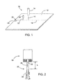
- FIG. 1 is a perspective view of a laser scoring and/or cutting apparatus.
- FIG. 2 is a side view of a stream of water discharging from a straight walled nozzle showing the coherent portion and the non-coherent portion.
- FIGS. 3A - 3C illustrate three simple nozzles, a divergent nozzle, a straight walled nozzle and a convergent nozzle, respectively.
- FIG. 4 is a plot of coherence length vs. pressure for an exemplary nozzle having a straight walled cylindrical orifice.
- FIG. 5 is a front view of an exemplary fusion downdraw apparatus for producing glass sheet comprising lasers and cooling nozzles for separating edges from a continuous glass ribbon formed by the apparatus.
- FIG. 1 Shown in FIG. 1 is an exemplary laser scoring an/or cutting apparatus 10 used to score or cut (e.g. full body cut) a sheet of brittle material 12, such as a sheet of glass, glass ceramic or ceramic, comprising a laser 14 that produces a beam of electromagnetic energy (light) 16 that irradiates and heats a portion of the sheet along a predetermined path 18.
- the predetermined path originates with a pre-existing flaw 20 formed at an edge of the sheet.
- the heated portion of the sheet is subsequently cooled by a closely following stream of cooling fluid 22 discharged by a nozzle 24.
- the heating, followed immediately by rapid cooling produces high stress in the sheet that drives a crack 26, such as produced by the pre-existing flaw, into the sheet and along the predetermined path.
- a liquid stream 22 produced by a simple nozzle opening goes through at least several phases depicted in FIG. 2 . Assuming a circular aperture, the stream begins as a substantially columnar flow 28 with little turbulence or surface degeneration (e.g. breakup at the stream surface leading to orphaned droplets, surface ripples etc.) and minimal entrained voids or bubbles over a distance L.
- turbulence or surface degeneration e.g. breakup at the stream surface leading to orphaned droplets, surface ripples etc.
- FIGS. 3A - 3C Three simple orifices are shown in FIGS. 3A - 3C.
- FIG. 3A illustrates a divergent nozzle 24, wherein the liquid leaving the nozzle aperture 30 immediately traverses an orifice 32 that rapidly expands in the form of a cone.
- FIG. 3B illustrates a straight walled nozzle 24 wherein the walls of the orifice 32 are substantially parallel.
- FIG. 3C depicts a convergent nozzle 24, wherein the liquid first traverses a converging cone-shaped portion of orifice 32 before exiting the nozzle aperture 30.
- nozzle refers to the overall structure of the member that forms the stream
- orifice describes the nozzle portion immediately adjacent the aperture (indicated by a dashed circle 32)
- aperture 30 refers to the planar geometric shape of the exit pupil from which the fluid exits the nozzle, generally selected as the narrowest portion of the orifice and indicated with a diameter D.
- each of the nozzles of FIGS. 3A - 3C comprises a circular aperture.
- FIGS. 3A and 3C illustrate conical orifices
- FIG. 3B depicts a cylindrical aperture.
- the aperture and the orifice are the same.
- the columnar nature of the stream degenerates into a turbulent, disassociated flow of droplets - in short, a non-coherent stream (e.g. a mist) represented by numeral 34.
- a non-coherent stream e.g. a mist
- inconsistent cooling may occur, leading to unsatisfactory scoring performance, such as deviation from an intended scoring and/or cutting path and weakened edges of the finally separated pieces.
- Several factors drive both the quality and extent of the columnar, or coherent, portion 28 of stream 22: the quality of the aperture inside edge and the length L of the columnar portion of the stream.
- coherent or coherence shall be used to describe a substantially columnar flow of liquid from a nozzle without significant surface disruption and/or generation of separate (orphaned or accompanying) droplets of liquid originating from the stream surface. More simply put, a coherent flow is a substantially cylindrical flow of liquid, and the length L of this region shall be referred to as the coherence length.
- the use of a coherent stream of cooling liquid can halve the conventional deviation performance, producing scoring and/or cutting paths with a deviation less than about +/- 11 micrometers vs. the typical +/- 20 micrometers produced by conventional laser scoring/cutting techniques.
- FIG. 4 depicts a plot of coherence length vs. pressure for a stream of water produced by a nozzle with a straight walled cylindrical orifice having an aperture with a diameter D of approximately 200 micrometers.
- the coherence length of this stream can exceed 50 mm, depending on the pressure driving the liquid. Above a given pressure, the coherence length rapidly deteriorates, reducing the useable working distance.
- FIG. 4 shows that pressurizing the water (such as with pressurized air) to a pressure between about 0.35 kg/cm 2 and 0.70 kg/cm 2 results in a coherence length between about 51 mm and 53 mm.
- a pressure of between about 0.70 kg/cm 2 and about 1 kg/cm 2 still delivers a respectable coherence length of greater than about 30 mm.
- a long coherence length is useful, for example, when scoring and/or cutting a brittle material having an uneven surface.
- a stream having a long coherence length enables a long working distance between the nozzle aperture and the work piece (brittle material), and movement of the nozzle as the surface topology varies is unnecessary and facilitates faster scoring and/or cutting speed.
- working distances in excess of 5 mm may be used, such as a working distance in the range between about 10 mm and 50 mm, in a range between 20 mm and 50 mm, in a range between 30 mm and 50 mm or in a range between 40 mm and 50 mm.
- a surface of a brittle material is irradiated and heated along a predetermined path with a laser beam produced by a laser, and quickly thereafter cooled with a stream of liquid discharged by a nozzle.
- the nozzle may be, for example, a simple divergent or straight walled nozzle having a circularly symmetric aperture and orifice.
- a coherence length of the stream is equal to or greater than 50 mm, and a distance between the nozzle aperture and the surface of the brittle material is less than the coherence length of the stream.
- a diameter of the coherent stream is in the range between 70 micrometers and 150 micrometers.
- a coherent stream of cooling liquid also facilitates accurate scoring and/or cutting of brittle material at high temperature, such as separating the edges from a glass ribbon as the high temperature ribbon is drawn from a forming apparatus.
- the drawing of a glass ribbon is well known in the art, and will not be described in detail, however, such methods include float methods, downdraw methods including fusion downdraw and slot draw, and up draw methods.
- a molten glass is flowed over converging forming surfaces 36 that meet along a line 38 at the bottom of the forming body, commonly called a root.
- the separate streams of molten glass coming from the converging forming surfaces join, or fuse, to form a single ribbon of glass 40.
- Glass ribbon 40 comprises a viscous region, a visco-elastic region and an elastic region.
- Glass ribbon 40 is contacted by various edge rolls 42 that grip edges 44 of the ribbon in the viscous and/or visco-elastic region and, depending on their specific function, guide or pull the glass ribbon. The contact between the edge rolls 42 and edges 44 mars the edges and makes the glass unsatisfactory for sale.
- laser cutting of the ribbon edge portions from the ribbon can be facilitated by employing a laser cutting method that employs a coherent stream of cooling liquid as described above.
- Laser beams 16 irradiate the glass ribbon along predetermined paths 18 generally parallel to the side edges of ribbon 40 in the elastic region of the ribbon.
- coherent streams 22 of cooling liquid e.g. water
- a coherence length of the streams is equal to or greater than 50 mm, and a distance between the nozzle apertures and the surface of the ribbon is less than the coherence length of the stream.
- a diameter of the coherent streams is in the range between 70 micrometers and 200 micrometers, and preferably in the range between 70 micrometers and 150 micrometers. This technique has been successfully demonstrated on non-flat glass ribbon at a temperature in excess of 300°C in the elastic region of the ribbon and having a bow (deviation from flat) of up to 20 mm.
- Exemplary, non-limiting embodiments according to the present invention include:
- a method of forming a vent crack in a brittle material comprising:
- a method of separating edges of a glass ribbon comprising:
Landscapes
- Engineering & Computer Science (AREA)
- Physics & Mathematics (AREA)
- Chemical & Material Sciences (AREA)
- Optics & Photonics (AREA)
- Mechanical Engineering (AREA)
- Plasma & Fusion (AREA)
- Materials Engineering (AREA)
- Organic Chemistry (AREA)
- Thermal Sciences (AREA)
- Toxicology (AREA)
- Health & Medical Sciences (AREA)
- Re-Forming, After-Treatment, Cutting And Transporting Of Glass Products (AREA)
- Processing Of Stones Or Stones Resemblance Materials (AREA)
Abstract
Description
- This application claims the benefit of
U.S. Application Serial No. 12/621,068, filed on November 18, 2009 - This invention is directed to a method of scoring and/or separating a brittle material, such as a glass or ceramic material.
- One method of cutting a brittle material includes making a mechanical score on a surface of the brittle material. The score can produce a small crack that extends essentially perpendicular to the surface of the material, and may sometimes be referred to as a vent crack or simply vent. Stress applied to the score line, such that a tension stress is produced across the score line (and consequently the vent crack), grows the vent so that it extends across the full thickness of the material, thereby separating the material into several pieces. The stress may be applied, for example, by bending the material, hence a term often applied to the technique is "score and snap".
- The mechanical score and snap method, wherein a score is produced by the mechanical application of a hard scoring wheel or scribe, suffers in that substantial damage is done to the surface, and to some meaningful depth into the brittle material, so that the edges of the separated pieces are weakened by the presence of small cracks or chips produced during the scoring.
- To alleviate this damage, laser scoring techniques were developed that used a laser beam to form a score line, after which stress was again applied. According to this technique, a surface of the brittle material was heated by a laser beam. A cooling fluid was then applied to the heated glass, and the accompanying high stress was capable of producing a rupture of the brittle material at the surface thereof and forming a vent crack. Separation occurred after the subsequent application of a bending stress. Variations of the technique include so-called full body separation wherein, instead of first forming a score line, the heating and cooling is sufficient to produce a vent that extends through the full thickness of the brittle material without the application of a subsequent bending stress. While laser scoring has proved to be superior to mechanical scoring, the technique suffers from inconsistencies, largely as a result of the cooling phase.
- A method of separating a brittle material, such as a sheet of glass, is disclosed. The method employs a laser to heat the brittle material along a predetermined path, followed by a stream of a cooling fluid, for example, water, produced by a nozzle that cools the heated predetermined path. The nozzle is capable of producing a stream that is substantially columnar (i.e. substantially cylindrical) for at least about 30 mm, preferably in excess of 50 mm. The length of the columnar portion of the stream is referred to as the coherence length of the stream. It has been found that consistency of the separation process, such as in the straightness of the score or cut, uniformity of the vent depth and overall process repeatability can be significantly increased if the coherent portion of the stream contacts the brittle material along the heated predetermined path.
- In one embodiment, a method of forming a vent crack in a brittle material comprising heating a surface of the brittle material with a laser along a predetermined path, cooling the heated surface of the brittle material with a coherent stream of cooling liquid dispensed by a nozzle, the stream comprising a coherence length equal to or greater than 50 mm and a diameter in the range from about 70 micrometers to about 150 micrometers and wherein a working distance between the nozzle aperture and the surface of the brittle material is less than the coherence length of the stream.
- Preferably, the coherent stream of cooling liquid is formed by a convergent nozzle with a circularly symmetric aperture. In other embodiments the coherent stream of cooling liquid is formed by a nozzle having a straight walled orifice with a circularly symmetric aperture. The working distance between the aperture of the nozzle and the surface of the brittle material is greater than 5 mm, and in some instances can be in excess of 50 mm.
- The brittle material may be glass, and in some embodiments is a continuous ribbon of glass, such as might be produced in a fusion downdraw process.
- If the brittle material is to be separated by the application of a mechanical stress, the vent crack may comprise a score (score line). In this instance, a tension stress may be produced across the score line by bending, or a tension may be produced by applying a linear force on the material (for example, by applying a pulling force).
- In other cases, the vent crack can extend through a full thickness of the brittle material after the cooling such that the brittle material is separated.
- Some applications of the method comprise separating a glass ribbon, wherein the ribbon has a temperature that exceeds 300°C. The ribbon may be non-planar, in which case the long working distance (e.g. long coherence length) of the stream allows for cutting and/or scoring without adjusting the position of the nozzle relative to the surface of the ribbon. That is, the distance between the nozzle aperture and the surface of the brittle material varies along the predetermined path, but without significant effect on the character of the formed vent crack.
- Preferably, a pressure of the cooling liquid in the nozzle is in a range between about 0.35 kg/cm2 and about 0.70 kg/cm2.
- In another embodiment, a method of separating edges of a glass ribbon is disclosed comprising forming a continuous ribbon of glass, the continuous ribbon of glass comprising a viscous region and an elastic region, heating a surface of the continuous ribbon of glass in the elastic region with a laser along a predetermined path. The heated predetermined path is then cooled with a coherent stream of cooling liquid dispensed by a nozzle, the stream comprising a coherence length equal to or greater than 50 mm and a diameter in the range from about 70 micrometers to about 150 micrometers to separate an edge from the continuous ribbon of glass. A working distance between the nozzle aperture and the surface of the continuous ribbon of glass is less than the coherence length of the stream.
- In some instances a temperature of the continuous ribbon of glass in the elastic region before the heating is greater than about 300°C. Preferably, the working distance between the nozzle aperture and the surface of the continuous ribbon of glass is greater than about 5 mm. Preferably, the pressure of the cooling liquid in the nozzle is in a range between about 0.35 kg/cm2 and about 0.70 kg/cm2. The nozzle preferably comprises a divergent, circularly symmetric orifice or a straight walled, circularly symmetric orifice
- In some embodiment, the continuous ribbon of glass in the elastic region is non-planar.
- The invention will be understood more easily and other objects, characteristics, details and advantages thereof will become more clearly apparent in the course of the following explanatory description, which is given, without in any way implying a limitation, with reference to the attached Figures. It is intended that all such additional systems, methods, features and advantages be included within this description, be within the scope of the present invention, and be protected by the accompanying claims.
-
FIG. 1 is a perspective view of a laser scoring and/or cutting apparatus. -
FIG. 2 is a side view of a stream of water discharging from a straight walled nozzle showing the coherent portion and the non-coherent portion. -
FIGS. 3A - 3C illustrate three simple nozzles, a divergent nozzle, a straight walled nozzle and a convergent nozzle, respectively. -
FIG. 4 is a plot of coherence length vs. pressure for an exemplary nozzle having a straight walled cylindrical orifice. -
FIG. 5 is a front view of an exemplary fusion downdraw apparatus for producing glass sheet comprising lasers and cooling nozzles for separating edges from a continuous glass ribbon formed by the apparatus. - In the following detailed description, for purposes of explanation and not limitation, example embodiments disclosing specific details are set forth to provide a thorough understanding of the present invention. However, it will be apparent to one having ordinary skill in the art, having had the benefit of the present disclosure, that the present invention may be practiced in other embodiments that depart from the specific details disclosed herein. Moreover, descriptions of well-known devices, methods and materials may be omitted so as not to obscure the description of the present invention. Finally, wherever applicable, like reference numerals refer to like elements.
- While laser scoring techniques employing a laser to first heat a brittle material along a predetermined line and wherein the heated zone on the brittle material is immediately cooled by a cooling fluid, are well known in the art. However, while laser scoring is superior to mechanical scoring techniques in terms of the resultant edge strength, they may suffer from inconsistencies in the vent crack formation that can lead to wander of the vent (undesired changes in the vent propagation direction at the surface of the brittle material) and variations in the vent propagation in a direction transverse to the surface. More simply, the depth of the vent crack can vary, resulting in a variation in the quality of the edge surface of the finally separated individual pieces. This inconsistency can be traced to the nature of cooling.
- Shown in
FIG. 1 is an exemplary laser scoring an/or cuttingapparatus 10 used to score or cut (e.g. full body cut) a sheet ofbrittle material 12, such as a sheet of glass, glass ceramic or ceramic, comprising alaser 14 that produces a beam of electromagnetic energy (light) 16 that irradiates and heats a portion of the sheet along a predeterminedpath 18. In some embodiments, the predetermined path originates with apre-existing flaw 20 formed at an edge of the sheet. The heated portion of the sheet is subsequently cooled by a closely following stream ofcooling fluid 22 discharged by anozzle 24. The heating, followed immediately by rapid cooling, produces high stress in the sheet that drives acrack 26, such as produced by the pre-existing flaw, into the sheet and along the predetermined path. - A
liquid stream 22 produced by a simple nozzle opening goes through at least several phases depicted inFIG. 2 . Assuming a circular aperture, the stream begins as a substantiallycolumnar flow 28 with little turbulence or surface degeneration (e.g. breakup at the stream surface leading to orphaned droplets, surface ripples etc.) and minimal entrained voids or bubbles over a distance L. - By simple nozzle what is meant is a single, circularly symmetric orifice. Three simple orifices are shown in
FIGS. 3A - 3C. FIG. 3A illustrates adivergent nozzle 24, wherein the liquid leaving thenozzle aperture 30 immediately traverses anorifice 32 that rapidly expands in the form of a cone.FIG. 3B illustrates a straightwalled nozzle 24 wherein the walls of theorifice 32 are substantially parallel. Finally,FIG. 3C depicts aconvergent nozzle 24, wherein the liquid first traverses a converging cone-shaped portion oforifice 32 before exiting thenozzle aperture 30. For the purpose of eliminating confusion, as used herein nozzle refers to the overall structure of the member that forms the stream, orifice describes the nozzle portion immediately adjacent the aperture (indicated by a dashed circle 32), andaperture 30 refers to the planar geometric shape of the exit pupil from which the fluid exits the nozzle, generally selected as the narrowest portion of the orifice and indicated with a diameter D. As can be seen, each of the nozzles ofFIGS. 3A - 3C comprises a circular aperture.FIGS. 3A and 3C illustrate conical orifices, whileFIG. 3B depicts a cylindrical aperture. For a straight walled nozzle, the aperture and the orifice are the same. - Returning to
FIG. 2 , in a second phase, the columnar nature of the stream degenerates into a turbulent, disassociated flow of droplets - in short, a non-coherent stream (e.g. a mist) represented bynumeral 34. If the mist portion ofstream 22 is incident on the surface of the brittle material, inconsistent cooling may occur, leading to unsatisfactory scoring performance, such as deviation from an intended scoring and/or cutting path and weakened edges of the finally separated pieces. Several factors drive both the quality and extent of the columnar, or coherent,portion 28 of stream 22: the quality of the aperture inside edge and the length L of the columnar portion of the stream. As used hereinafter, the term coherent or coherence, shall be used to describe a substantially columnar flow of liquid from a nozzle without significant surface disruption and/or generation of separate (orphaned or accompanying) droplets of liquid originating from the stream surface. More simply put, a coherent flow is a substantially cylindrical flow of liquid, and the length L of this region shall be referred to as the coherence length. The use of a coherent stream of cooling liquid can halve the conventional deviation performance, producing scoring and/or cutting paths with a deviation less than about +/- 11 micrometers vs. the typical +/- 20 micrometers produced by conventional laser scoring/cutting techniques. -
FIG. 4 depicts a plot of coherence length vs. pressure for a stream of water produced by a nozzle with a straight walled cylindrical orifice having an aperture with a diameter D of approximately 200 micrometers. As is evident from the plot, the coherence length of this stream can exceed 50 mm, depending on the pressure driving the liquid. Above a given pressure, the coherence length rapidly deteriorates, reducing the useable working distance.FIG. 4 shows that pressurizing the water (such as with pressurized air) to a pressure between about 0.35 kg/cm2 and 0.70 kg/cm2 results in a coherence length between about 51 mm and 53 mm. A pressure of between about 0.70 kg/cm2 and about 1 kg/cm2 still delivers a respectable coherence length of greater than about 30 mm. - A long coherence length is useful, for example, when scoring and/or cutting a brittle material having an uneven surface. By employing a stream having a long coherence length enables a long working distance between the nozzle aperture and the work piece (brittle material), and movement of the nozzle as the surface topology varies is unnecessary and facilitates faster scoring and/or cutting speed. For example, working distances in excess of 5 mm may be used, such as a working distance in the range between about 10 mm and 50 mm, in a range between 20 mm and 50 mm, in a range between 30 mm and 50 mm or in a range between 40 mm and 50 mm.
- In accordance with one embodiment, a surface of a brittle material is irradiated and heated along a predetermined path with a laser beam produced by a laser, and quickly thereafter cooled with a stream of liquid discharged by a nozzle. The nozzle may be, for example, a simple divergent or straight walled nozzle having a circularly symmetric aperture and orifice. A coherence length of the stream is equal to or greater than 50 mm, and a distance between the nozzle aperture and the surface of the brittle material is less than the coherence length of the stream. A diameter of the coherent stream is in the range between 70 micrometers and 150 micrometers.
- The use of a coherent stream of cooling liquid also facilitates accurate scoring and/or cutting of brittle material at high temperature, such as separating the edges from a glass ribbon as the high temperature ribbon is drawn from a forming apparatus. The drawing of a glass ribbon is well known in the art, and will not be described in detail, however, such methods include float methods, downdraw methods including fusion downdraw and slot draw, and up draw methods.
- In an exemplary fusion downdraw method, illustrated in
FIG. 5 , a molten glass is flowed over converging formingsurfaces 36 that meet along aline 38 at the bottom of the forming body, commonly called a root. At the root, the separate streams of molten glass coming from the converging forming surfaces join, or fuse, to form a single ribbon ofglass 40.Glass ribbon 40 comprises a viscous region, a visco-elastic region and an elastic region.Glass ribbon 40 is contacted by various edge rolls 42 that grip edges 44 of the ribbon in the viscous and/or visco-elastic region and, depending on their specific function, guide or pull the glass ribbon. The contact between the edge rolls 42 andedges 44 mars the edges and makes the glass unsatisfactory for sale. Consequently, the ribbon edges must be removed. While edge removal can be performed after a separate sheet of glass is removed from the ribbon at the bottom of the draw area, removal of the edges directly from the ribbon offers greater manufacturing efficiency. In accordance with the present embodiment, laser cutting of the ribbon edge portions from the ribbon can be facilitated by employing a laser cutting method that employs a coherent stream of cooling liquid as described above.Laser beams 16 irradiate the glass ribbon alongpredetermined paths 18 generally parallel to the side edges ofribbon 40 in the elastic region of the ribbon. Next,coherent streams 22 of cooling liquid (e.g. water) are directed along the predetermined paths to separate the edges from the ribbon. A coherence length of the streams is equal to or greater than 50 mm, and a distance between the nozzle apertures and the surface of the ribbon is less than the coherence length of the stream. A diameter of the coherent streams is in the range between 70 micrometers and 200 micrometers, and preferably in the range between 70 micrometers and 150 micrometers. This technique has been successfully demonstrated on non-flat glass ribbon at a temperature in excess of 300°C in the elastic region of the ribbon and having a bow (deviation from flat) of up to 20 mm. - Exemplary, non-limiting embodiments according to the present invention include:
- C1. A method of forming a vent crack in a brittle material comprising:
- heating a surface of the brittle material with a laser along a predetermined path;
- cooling the heated surface of the brittle material with a coherent stream of cooling liquid dispensed by a nozzle to produce a vent crack, the stream comprising a coherence length equal to or greater than 50 mm and a diameter in the range from about 70 micrometers to about 200 micrometers; and
- C2. The method according to C1, wherein the coherent stream of cooling liquid is formed by a divergent nozzle with a circularly symmetric aperture.
- C3. The method according to C1, wherein the coherent stream of cooling liquid is formed by a nozzle having a straight walled cylindrical orifice.
- C4. The method according to any of C1 - C3, wherein the working distance is greater than 5 mm.
- C5. The method according to any of C1 - C4, wherein the brittle material is glass.
- C6. The method according to C5, wherein the brittle material is a continuous ribbon of glass.
- C7. The method according to C6 wherein the ribbon was produced in a fusion downdraw process.
- C8. The method according to any of C1 - C7, wherein the vent crack comprises a score.
- C9. The method according to any of C1 - C8, wherein the vent crack extends through a full thickness of the brittle material after the cooling such that the brittle material is separated into a plurality of segments.
- C10. The method according to C6, wherein a temperature of the glass exceeds 300°C.
- C11. The method according to C6, wherein the ribbon was non-planar.
- C12. The method according to any of C1 - C11, wherein the distance between the nozzle aperture and the surface of the brittle material varies along the predetermined path.
- C13. The method according to any of C1 - C12, wherein a pressure of the liquid in the nozzle is in a range between about 0.35 kg/cm2 and about 0.70 kg/cm2.
- C14. A method of separating edges of a glass ribbon comprising:
- forming a continuous ribbon of glass, the continuous ribbon of glass comprising a viscous region and an elastic region
- heating a surface of the continuous ribbon of glass in the elastic region with a laser along a predetermined path;
- cooling the heated surface of the continuous ribbon of glass with a coherent stream of cooling liquid dispensed by a nozzle, the stream comprising a coherence length equal to or greater than 50 mm and a diameter in the range from about 70 micrometers to about 150 micrometers to separate an edge from the continuous ribbon of glass; and
- wherein a working distance between the nozzle aperture and the surface of the continuous ribbon of glass is less than the coherence length of the stream.
- C15. The method according to C14, wherein a temperature of the glass in the elastic region before the heating is greater than about 300°C.
-
C 16. The method according toC 14 or C15, wherein the working distance between the nozzle aperture and the surface of the continuous ribbon of glass is greater than about 5 mm. - C17. The method according to any of C14 - C16, wherein the pressure of the cooling liquid in the nozzle is in a range between about 0.35 kg/cm2 and about 0.70 kg/cm2.
- C18. The method according to any of C14 - C 17, wherein the continuous ribbon of glass in the elastic region is non-planar.
- C19. The method according to any of C14 - C18, wherein the nozzle comprises a divergent, circularly symmetric orifice.
- C20. The method according to any of C14 - C19, wherein the nozzle comprises a straight walled, circularly symmetric orifice.
- It should be emphasized that the above-described embodiments of the present invention, particularly any "preferred" embodiments, are merely possible examples of implementations, merely set forth for a clear understanding of the principles of the invention. Many variations and modifications may be made to the above-described embodiments of the invention without departing substantially from the spirit and principles of the invention. All such modifications and variations are intended to be included herein within the scope of this disclosure and the present invention and protected by the following claims.
Claims (13)
- A method of forming a vent crack in a brittle material comprising:heating a surface of the brittle material with a laser along a predetermined path;cooling the heated surface of the brittle material with a coherent stream of cooling liquid dispensed by a nozzle to produce a vent crack in the brittle material, the stream comprising a coherence length equal to or greater than 50 mm and a diameter in the range from about 70 micrometers to about 200 micrometers; andwherein a working distance between the nozzle aperture and the surface of the brittle material is less than the coherence length of the stream.
- The method according to claim 1, wherein the coherent stream of cooling liquid is formed by a divergent nozzle with a circularly symmetric aperture.
- The method according to claim 1 or claim 2, wherein the coherent stream of cooling liquid is formed by a nozzle having a straight walled cylindrical orifice.
- The method according to any of claims 1 to 3, wherein the working distance is greater than 5 mm.
- The method according to any of claims 1 to 4, wherein the brittle material is glass.
- The method according to any of claims 1 to 4, wherein the brittle material is a continuous ribbon of glass.
- The method according to claim 6 wherein the ribbon was produced in a fusion downdraw process.
- The method according to any preceding claim, wherein the vent crack comprises a score.
- The method according to any of claims 1 to 7, wherein the vent crack extends through a full thickness of the brittle material after the cooling such that the brittle material is separated into a plurality of segments.
- The method according to claim 6, wherein a temperature of the glass exceeds 300°C.
- The method according to claim 6 or 10, wherein the ribbon is non-planar.
- The method according to any preceding claim, wherein the working distance between the nozzle aperture and the surface of the brittle material varies along the predetermined path.
- The method according to any preceding claim, wherein a pressure of the liquid in the nozzle is in a range between about 0.35 kg/cm2 and about 0.70 kg/cm2.
Applications Claiming Priority (1)
| Application Number | Priority Date | Filing Date | Title |
|---|---|---|---|
| US12/621,068 US8171753B2 (en) | 2009-11-18 | 2009-11-18 | Method for cutting a brittle material |
Publications (2)
| Publication Number | Publication Date |
|---|---|
| EP2332890A1 true EP2332890A1 (en) | 2011-06-15 |
| EP2332890B1 EP2332890B1 (en) | 2012-08-22 |
Family
ID=43332619
Family Applications (1)
| Application Number | Title | Priority Date | Filing Date |
|---|---|---|---|
| EP10190949A Not-in-force EP2332890B1 (en) | 2009-11-18 | 2010-11-12 | Method for cutting a brittle material |
Country Status (6)
| Country | Link |
|---|---|
| US (1) | US8171753B2 (en) |
| EP (1) | EP2332890B1 (en) |
| JP (1) | JP5563430B2 (en) |
| KR (1) | KR101605917B1 (en) |
| CN (1) | CN102167505A (en) |
| TW (1) | TWI417262B (en) |
Cited By (1)
| Publication number | Priority date | Publication date | Assignee | Title |
|---|---|---|---|---|
| US10941070B2 (en) | 2014-02-20 | 2021-03-09 | Corning Incorporated | Methods and apparatus for cutting radii in flexible thin glass |
Families Citing this family (16)
| Publication number | Priority date | Publication date | Assignee | Title |
|---|---|---|---|---|
| CN102203943B (en) * | 2008-10-29 | 2013-07-31 | 欧瑞康太阳能股份公司(特吕巴赫) | Method for dividing a semiconductor film formed on a substrate into plural regions by multiple laser beam irradiation |
| US8932510B2 (en) | 2009-08-28 | 2015-01-13 | Corning Incorporated | Methods for laser cutting glass substrates |
| US8946590B2 (en) | 2009-11-30 | 2015-02-03 | Corning Incorporated | Methods for laser scribing and separating glass substrates |
| JP5696393B2 (en) * | 2010-08-02 | 2015-04-08 | 日本電気硝子株式会社 | Cleaving method of glass film |
| TWI513670B (en) * | 2010-08-31 | 2015-12-21 | Corning Inc | Methods of separating strengthened glass substrates |
| US8677783B2 (en) | 2011-11-28 | 2014-03-25 | Corning Incorporated | Method for low energy separation of a glass ribbon |
| US9938180B2 (en) | 2012-06-05 | 2018-04-10 | Corning Incorporated | Methods of cutting glass using a laser |
| US9610653B2 (en) | 2012-09-21 | 2017-04-04 | Electro Scientific Industries, Inc. | Method and apparatus for separation of workpieces and articles produced thereby |
| CN105189022B (en) | 2013-01-30 | 2017-09-01 | 康宁股份有限公司 | The apparatus and method cut for flexible glass continuous laser |
| CN103288340B (en) * | 2013-05-20 | 2016-08-10 | 深圳市华星光电技术有限公司 | The cutting splitting device of glass substrate and cutting splitting method thereof |
| US9260337B2 (en) | 2014-01-09 | 2016-02-16 | Corning Incorporated | Methods and apparatus for free-shape cutting of flexible thin glass |
| US10017411B2 (en) * | 2014-11-19 | 2018-07-10 | Corning Incorporated | Methods of separating a glass web |
| WO2017091529A1 (en) * | 2015-11-25 | 2017-06-01 | Corning Incorporated | Methods of separating a glass web |
| DE102019113635A1 (en) * | 2019-05-22 | 2020-11-26 | Schott Ag | Method and device for processing glass elements |
| CN111014961A (en) * | 2019-12-25 | 2020-04-17 | 深圳市韵腾激光科技有限公司 | Laser cutting lobe of a leaf device |
| CN114734153B (en) * | 2022-03-31 | 2023-02-14 | 武汉华日精密激光股份有限公司 | Splitting method and system for processing brittle material by laser |
Citations (1)
| Publication number | Priority date | Publication date | Assignee | Title |
|---|---|---|---|---|
| US20080283509A1 (en) * | 2007-05-15 | 2008-11-20 | Anatoli Anatolyevich Abramov | Method and apparatus for scoring and separating a brittle material with a single beam of radiation |
Family Cites Families (46)
| Publication number | Priority date | Publication date | Assignee | Title |
|---|---|---|---|---|
| US2589183A (en) * | 1948-11-12 | 1952-03-11 | Zielinski Joseph | High-pressure jet nozzle |
| JPS4867145A (en) * | 1971-12-20 | 1973-09-13 | ||
| DE2619415C2 (en) * | 1976-05-03 | 1986-01-02 | Dietz-Armaturen Gmbh, 5060 Bergisch Gladbach | Dousing shower for generating a free-falling flat jet of liquid |
| JPH0221955A (en) * | 1988-07-07 | 1990-01-24 | Nippon Steel Corp | Fluid injection nozzle |
| RU2024441C1 (en) | 1992-04-02 | 1994-12-15 | Владимир Степанович Кондратенко | Process of cutting of nonmetal materials |
| DE69315643T2 (en) | 1992-09-01 | 1998-04-02 | Corning Inc | Cutting glass panes |
| JP3255479B2 (en) | 1993-02-26 | 2002-02-12 | 東芝テック株式会社 | Inkjet printer |
| US5622540A (en) | 1994-09-19 | 1997-04-22 | Corning Incorporated | Method for breaking a glass sheet |
| DE69629704T2 (en) | 1995-08-31 | 2004-07-08 | Corning Inc. | METHOD AND DEVICE FOR BREAKING BRITTLE MATERIAL |
| US6407360B1 (en) * | 1998-08-26 | 2002-06-18 | Samsung Electronics, Co., Ltd. | Laser cutting apparatus and method |
| US6211488B1 (en) * | 1998-12-01 | 2001-04-03 | Accudyne Display And Semiconductor Systems, Inc. | Method and apparatus for separating non-metallic substrates utilizing a laser initiated scribe |
| US6420678B1 (en) * | 1998-12-01 | 2002-07-16 | Brian L. Hoekstra | Method for separating non-metallic substrates |
| US6252197B1 (en) * | 1998-12-01 | 2001-06-26 | Accudyne Display And Semiconductor Systems, Inc. | Method and apparatus for separating non-metallic substrates utilizing a supplemental mechanical force applicator |
| US6259058B1 (en) * | 1998-12-01 | 2001-07-10 | Accudyne Display And Semiconductor Systems, Inc. | Apparatus for separating non-metallic substrates |
| US6327875B1 (en) * | 1999-03-09 | 2001-12-11 | Corning Incorporated | Control of median crack depth in laser scoring |
| DE19952331C1 (en) * | 1999-10-29 | 2001-08-30 | Schott Spezialglas Gmbh | Method and device for quickly cutting a workpiece from brittle material using laser beams |
| JP3895179B2 (en) * | 1999-11-24 | 2007-03-22 | アプライド・フォトニクス・インコーポレーテッド | Method and apparatus for separating non-metallic substrates |
| DE19959921C1 (en) * | 1999-12-11 | 2001-10-18 | Schott Spezialglas Gmbh | Method and device for cutting flat workpieces made of brittle material |
| DE19963939B4 (en) * | 1999-12-31 | 2004-11-04 | Schott Spezialglas Gmbh | Method and device for cutting flat workpieces made of brittle material |
| US6732952B2 (en) * | 2001-06-08 | 2004-05-11 | Carl L. C. Kah, Jr. | Oscillating nozzle sprinkler with integrated adjustable arc, precipitation rate, flow rate, and range of coverage |
| KR100490048B1 (en) * | 2001-06-19 | 2005-05-17 | 삼성전자주식회사 | In-line system for manufacturing liquid crystal display and method of manufacturing liquid crystal display using the same |
| TW568809B (en) * | 2001-09-21 | 2004-01-01 | Mitsuboshi Diamond Ind Co Ltd | Method for scribing substrate of brittle material and scriber |
| DE10148777B4 (en) * | 2001-10-02 | 2019-01-24 | Air Liquide Deutschland Gmbh | Method and apparatus for cooling a mass of a substance |
| US6744009B1 (en) * | 2002-04-02 | 2004-06-01 | Seagate Technology Llc | Combined laser-scribing and laser-breaking for shaping of brittle substrates |
| EP1690835B1 (en) | 2003-12-05 | 2011-08-17 | Asahi Glass Company Ltd. | Method for cutting glass plates |
| US7185833B2 (en) * | 2004-03-18 | 2007-03-06 | Ernest Geskin | Method for fluid jet formation and apparatus for the same |
| US7820941B2 (en) | 2004-07-30 | 2010-10-26 | Corning Incorporated | Process and apparatus for scoring a brittle material |
| US20060021977A1 (en) | 2004-07-30 | 2006-02-02 | Menegus Harry E | Process and apparatus for scoring a brittle material incorporating moving optical assembly |
| JP4457933B2 (en) * | 2005-03-18 | 2010-04-28 | 澁谷工業株式会社 | Hybrid laser processing equipment |
| US20070039990A1 (en) | 2005-05-06 | 2007-02-22 | Kemmerer Marvin W | Impact induced crack propagation in a brittle material |
| DE102005024563B9 (en) * | 2005-05-28 | 2006-12-14 | Schott Ag | Process for separating glass and using a suitable liquid |
| WO2007018586A1 (en) | 2005-07-28 | 2007-02-15 | Gyrotron Technology, Inc. | A method of separating non-metallic material using microwave radiation |
| GB0519111D0 (en) | 2005-09-20 | 2005-10-26 | Pilkington Deutschland Ag | Glass cutting |
| US20070140311A1 (en) * | 2005-12-20 | 2007-06-21 | House Keith L | Method and apparatus for characterizing a glass ribbon |
| DE102006024825A1 (en) * | 2006-05-23 | 2007-11-29 | Jenoptik Automatisierungstechnik Gmbh | Method and device for edge trimming a float glass ribbon |
| JP2008044804A (en) * | 2006-08-11 | 2008-02-28 | Shibaura Mechatronics Corp | Cleaving device and cleaving method |
| US20080213978A1 (en) * | 2007-03-03 | 2008-09-04 | Dynatex | Debris management for wafer singulation |
| DE202006016674U1 (en) * | 2006-10-27 | 2007-02-22 | Nordson Corporation, Westlake | Application device for flat application of liquid material, especially hot melt glue, has clamping device for fastening of nozzle arrangement on basic body |
| JP2008229715A (en) * | 2007-03-23 | 2008-10-02 | Toray Eng Co Ltd | Laser scribing apparatus |
| CN101687686A (en) | 2007-04-30 | 2010-03-31 | 康宁股份有限公司 | Apparatus, system and method for scoring a moving glass ribbon |
| US7895861B2 (en) * | 2007-05-09 | 2011-03-01 | Corning Incorporated | Conformable nosing device for reducing motion and stress within a glass sheet while manufacturing the glass sheet |
| US20080290077A1 (en) | 2007-05-22 | 2008-11-27 | Demeritt Jeffery Alan | Separation of transparent glasses and systems and methods therefor |
| JP2010538475A (en) | 2007-08-31 | 2010-12-09 | アプライド マテリアルズ インコーポレイテッド | Production line module for forming multi-size photovoltaic devices |
| JP5192216B2 (en) * | 2007-11-09 | 2013-05-08 | 株式会社ディスコ | Laser processing equipment |
| US8011207B2 (en) | 2007-11-20 | 2011-09-06 | Corning Incorporated | Laser scoring of glass sheets at high speeds and with low residual stress |
| US20090178298A1 (en) | 2008-01-15 | 2009-07-16 | Anatoli Anatolyevich Abramov | Device for fluid removal after laser scoring |
-
2009
- 2009-11-18 US US12/621,068 patent/US8171753B2/en not_active Expired - Fee Related
-
2010
- 2010-11-08 TW TW099138385A patent/TWI417262B/en not_active IP Right Cessation
- 2010-11-11 KR KR1020100112027A patent/KR101605917B1/en not_active Expired - Fee Related
- 2010-11-12 EP EP10190949A patent/EP2332890B1/en not_active Not-in-force
- 2010-11-17 CN CN2010106238617A patent/CN102167505A/en active Pending
- 2010-11-18 JP JP2010257622A patent/JP5563430B2/en not_active Expired - Fee Related
Patent Citations (1)
| Publication number | Priority date | Publication date | Assignee | Title |
|---|---|---|---|---|
| US20080283509A1 (en) * | 2007-05-15 | 2008-11-20 | Anatoli Anatolyevich Abramov | Method and apparatus for scoring and separating a brittle material with a single beam of radiation |
Non-Patent Citations (2)
| Title |
|---|
| FRIEDL W: "ON-LINE LASER CUTTING OF THE FLOAT FIBBON", VERRE, INSTITUT DU VERRE, PARIS, FR, vol. 11, no. 6, 1 December 2005 (2005-12-01), pages 35 - 38, XP001240524, ISSN: 0984-7979 * |
| MORGAN M N ET AL: "Optimisation of fluid application in grinding", CIRP ANNALS, ELSEVIER BV, NL, CH, FR, vol. 57, no. 1, 1 January 2008 (2008-01-01), pages 363 - 366, XP022674675, ISSN: 0007-8506, [retrieved on 20080509], DOI: 10.1016/J.CIRP.2008.03.090 * |
Cited By (1)
| Publication number | Priority date | Publication date | Assignee | Title |
|---|---|---|---|---|
| US10941070B2 (en) | 2014-02-20 | 2021-03-09 | Corning Incorporated | Methods and apparatus for cutting radii in flexible thin glass |
Also Published As
| Publication number | Publication date |
|---|---|
| JP5563430B2 (en) | 2014-07-30 |
| JP2011116638A (en) | 2011-06-16 |
| TWI417262B (en) | 2013-12-01 |
| TW201127764A (en) | 2011-08-16 |
| KR20110055406A (en) | 2011-05-25 |
| CN102167505A (en) | 2011-08-31 |
| US20110113830A1 (en) | 2011-05-19 |
| US8171753B2 (en) | 2012-05-08 |
| EP2332890B1 (en) | 2012-08-22 |
| KR101605917B1 (en) | 2016-04-01 |
Similar Documents
| Publication | Publication Date | Title |
|---|---|---|
| EP2332890B1 (en) | Method for cutting a brittle material | |
| US8978417B2 (en) | Method for low energy separation of a glass ribbon | |
| TWI417261B (en) | Non-contact glass shearing device and method for scribing or cutting a moving glass sheet | |
| US8549881B2 (en) | Preventing gas from occupying a spray nozzle used in a process of scoring a hot glass sheet | |
| JP5574747B2 (en) | Method for marking sheets made of fragile materials | |
| JP6703482B2 (en) | Laser-cut composite glass article and cutting method | |
| US10407336B2 (en) | Method and apparatus for continuously cutting glass | |
| KR20120004456A (en) | Precision Laser Scoring | |
| JP2010509179A (en) | Sheet separation by fluid impact | |
| CN107438584A (en) | Method and apparatus for continuous separation of glasses | |
| CN107428588A (en) | Method by cutting glass by laser and the glass according to methods described production | |
| KR102073667B1 (en) | Laser fusion-cutting method for plate glass | |
| WO2009091510A1 (en) | Device and method for fluid removal after laser scoring | |
| US20220081343A1 (en) | Method and apparatus for cutting glass sheets |
Legal Events
| Date | Code | Title | Description |
|---|---|---|---|
| PUAI | Public reference made under article 153(3) epc to a published international application that has entered the european phase |
Free format text: ORIGINAL CODE: 0009012 |
|
| AK | Designated contracting states |
Kind code of ref document: A1 Designated state(s): AL AT BE BG CH CY CZ DE DK EE ES FI FR GB GR HR HU IE IS IT LI LT LU LV MC MK MT NL NO PL PT RO RS SE SI SK SM TR |
|
| AX | Request for extension of the european patent |
Extension state: BA ME |
|
| 17P | Request for examination filed |
Effective date: 20111019 |
|
| REG | Reference to a national code |
Ref country code: DE Ref legal event code: R079 Ref document number: 602010002459 Country of ref document: DE Free format text: PREVIOUS MAIN CLASS: C03B0033090000 Ipc: B23K0026420000 |
|
| RIC1 | Information provided on ipc code assigned before grant |
Ipc: B23K 26/14 20060101ALI20120131BHEP Ipc: C03B 33/02 20060101ALI20120131BHEP Ipc: B23K 26/40 20060101ALI20120131BHEP Ipc: C03B 33/09 20060101ALI20120131BHEP Ipc: B23K 37/00 20060101ALI20120131BHEP Ipc: B23K 26/42 20060101AFI20120131BHEP |
|
| GRAP | Despatch of communication of intention to grant a patent |
Free format text: ORIGINAL CODE: EPIDOSNIGR1 |
|
| GRAS | Grant fee paid |
Free format text: ORIGINAL CODE: EPIDOSNIGR3 |
|
| GRAA | (expected) grant |
Free format text: ORIGINAL CODE: 0009210 |
|
| AK | Designated contracting states |
Kind code of ref document: B1 Designated state(s): AL AT BE BG CH CY CZ DE DK EE ES FI FR GB GR HR HU IE IS IT LI LT LU LV MC MK MT NL NO PL PT RO RS SE SI SK SM TR |
|
| REG | Reference to a national code |
Ref country code: GB Ref legal event code: FG4D |
|
| REG | Reference to a national code |
Ref country code: CH Ref legal event code: EP |
|
| REG | Reference to a national code |
Ref country code: IE Ref legal event code: FG4D |
|
| REG | Reference to a national code |
Ref country code: AT Ref legal event code: REF Ref document number: 571682 Country of ref document: AT Kind code of ref document: T Effective date: 20120915 |
|
| REG | Reference to a national code |
Ref country code: DE Ref legal event code: R096 Ref document number: 602010002459 Country of ref document: DE Effective date: 20121018 |
|
| REG | Reference to a national code |
Ref country code: NL Ref legal event code: VDEP Effective date: 20120822 |
|
| REG | Reference to a national code |
Ref country code: AT Ref legal event code: MK05 Ref document number: 571682 Country of ref document: AT Kind code of ref document: T Effective date: 20120822 |
|
| REG | Reference to a national code |
Ref country code: LT Ref legal event code: MG4D Effective date: 20120822 |
|
| PG25 | Lapsed in a contracting state [announced via postgrant information from national office to epo] |
Ref country code: FI Free format text: LAPSE BECAUSE OF FAILURE TO SUBMIT A TRANSLATION OF THE DESCRIPTION OR TO PAY THE FEE WITHIN THE PRESCRIBED TIME-LIMIT Effective date: 20120822 Ref country code: AT Free format text: LAPSE BECAUSE OF FAILURE TO SUBMIT A TRANSLATION OF THE DESCRIPTION OR TO PAY THE FEE WITHIN THE PRESCRIBED TIME-LIMIT Effective date: 20120822 Ref country code: IS Free format text: LAPSE BECAUSE OF FAILURE TO SUBMIT A TRANSLATION OF THE DESCRIPTION OR TO PAY THE FEE WITHIN THE PRESCRIBED TIME-LIMIT Effective date: 20121222 Ref country code: LT Free format text: LAPSE BECAUSE OF FAILURE TO SUBMIT A TRANSLATION OF THE DESCRIPTION OR TO PAY THE FEE WITHIN THE PRESCRIBED TIME-LIMIT Effective date: 20120822 Ref country code: NO Free format text: LAPSE BECAUSE OF FAILURE TO SUBMIT A TRANSLATION OF THE DESCRIPTION OR TO PAY THE FEE WITHIN THE PRESCRIBED TIME-LIMIT Effective date: 20121122 Ref country code: HR Free format text: LAPSE BECAUSE OF FAILURE TO SUBMIT A TRANSLATION OF THE DESCRIPTION OR TO PAY THE FEE WITHIN THE PRESCRIBED TIME-LIMIT Effective date: 20120822 |
|
| PG25 | Lapsed in a contracting state [announced via postgrant information from national office to epo] |
Ref country code: LV Free format text: LAPSE BECAUSE OF FAILURE TO SUBMIT A TRANSLATION OF THE DESCRIPTION OR TO PAY THE FEE WITHIN THE PRESCRIBED TIME-LIMIT Effective date: 20120822 Ref country code: BE Free format text: LAPSE BECAUSE OF FAILURE TO SUBMIT A TRANSLATION OF THE DESCRIPTION OR TO PAY THE FEE WITHIN THE PRESCRIBED TIME-LIMIT Effective date: 20120822 Ref country code: PT Free format text: LAPSE BECAUSE OF FAILURE TO SUBMIT A TRANSLATION OF THE DESCRIPTION OR TO PAY THE FEE WITHIN THE PRESCRIBED TIME-LIMIT Effective date: 20121224 Ref country code: GR Free format text: LAPSE BECAUSE OF FAILURE TO SUBMIT A TRANSLATION OF THE DESCRIPTION OR TO PAY THE FEE WITHIN THE PRESCRIBED TIME-LIMIT Effective date: 20121123 Ref country code: SE Free format text: LAPSE BECAUSE OF FAILURE TO SUBMIT A TRANSLATION OF THE DESCRIPTION OR TO PAY THE FEE WITHIN THE PRESCRIBED TIME-LIMIT Effective date: 20120822 Ref country code: SI Free format text: LAPSE BECAUSE OF FAILURE TO SUBMIT A TRANSLATION OF THE DESCRIPTION OR TO PAY THE FEE WITHIN THE PRESCRIBED TIME-LIMIT Effective date: 20120822 |
|
| PG25 | Lapsed in a contracting state [announced via postgrant information from national office to epo] |
Ref country code: NL Free format text: LAPSE BECAUSE OF FAILURE TO SUBMIT A TRANSLATION OF THE DESCRIPTION OR TO PAY THE FEE WITHIN THE PRESCRIBED TIME-LIMIT Effective date: 20120822 |
|
| PG25 | Lapsed in a contracting state [announced via postgrant information from national office to epo] |
Ref country code: DK Free format text: LAPSE BECAUSE OF FAILURE TO SUBMIT A TRANSLATION OF THE DESCRIPTION OR TO PAY THE FEE WITHIN THE PRESCRIBED TIME-LIMIT Effective date: 20120822 Ref country code: RO Free format text: LAPSE BECAUSE OF FAILURE TO SUBMIT A TRANSLATION OF THE DESCRIPTION OR TO PAY THE FEE WITHIN THE PRESCRIBED TIME-LIMIT Effective date: 20120822 Ref country code: CZ Free format text: LAPSE BECAUSE OF FAILURE TO SUBMIT A TRANSLATION OF THE DESCRIPTION OR TO PAY THE FEE WITHIN THE PRESCRIBED TIME-LIMIT Effective date: 20120822 Ref country code: EE Free format text: LAPSE BECAUSE OF FAILURE TO SUBMIT A TRANSLATION OF THE DESCRIPTION OR TO PAY THE FEE WITHIN THE PRESCRIBED TIME-LIMIT Effective date: 20120822 Ref country code: ES Free format text: LAPSE BECAUSE OF FAILURE TO SUBMIT A TRANSLATION OF THE DESCRIPTION OR TO PAY THE FEE WITHIN THE PRESCRIBED TIME-LIMIT Effective date: 20121203 |
|
| PG25 | Lapsed in a contracting state [announced via postgrant information from national office to epo] |
Ref country code: IT Free format text: LAPSE BECAUSE OF FAILURE TO SUBMIT A TRANSLATION OF THE DESCRIPTION OR TO PAY THE FEE WITHIN THE PRESCRIBED TIME-LIMIT Effective date: 20120822 Ref country code: PL Free format text: LAPSE BECAUSE OF FAILURE TO SUBMIT A TRANSLATION OF THE DESCRIPTION OR TO PAY THE FEE WITHIN THE PRESCRIBED TIME-LIMIT Effective date: 20120822 Ref country code: SK Free format text: LAPSE BECAUSE OF FAILURE TO SUBMIT A TRANSLATION OF THE DESCRIPTION OR TO PAY THE FEE WITHIN THE PRESCRIBED TIME-LIMIT Effective date: 20120822 |
|
| PLBE | No opposition filed within time limit |
Free format text: ORIGINAL CODE: 0009261 |
|
| STAA | Information on the status of an ep patent application or granted ep patent |
Free format text: STATUS: NO OPPOSITION FILED WITHIN TIME LIMIT |
|
| 26N | No opposition filed |
Effective date: 20130523 |
|
| PG25 | Lapsed in a contracting state [announced via postgrant information from national office to epo] |
Ref country code: RS Free format text: LAPSE BECAUSE OF FAILURE TO SUBMIT A TRANSLATION OF THE DESCRIPTION OR TO PAY THE FEE WITHIN THE PRESCRIBED TIME-LIMIT Effective date: 20120822 Ref country code: BG Free format text: LAPSE BECAUSE OF FAILURE TO SUBMIT A TRANSLATION OF THE DESCRIPTION OR TO PAY THE FEE WITHIN THE PRESCRIBED TIME-LIMIT Effective date: 20121122 |
|
| REG | Reference to a national code |
Ref country code: IE Ref legal event code: MM4A |
|
| REG | Reference to a national code |
Ref country code: DE Ref legal event code: R097 Ref document number: 602010002459 Country of ref document: DE Effective date: 20130523 |
|
| PG25 | Lapsed in a contracting state [announced via postgrant information from national office to epo] |
Ref country code: IE Free format text: LAPSE BECAUSE OF NON-PAYMENT OF DUE FEES Effective date: 20121112 |
|
| PG25 | Lapsed in a contracting state [announced via postgrant information from national office to epo] |
Ref country code: MT Free format text: LAPSE BECAUSE OF FAILURE TO SUBMIT A TRANSLATION OF THE DESCRIPTION OR TO PAY THE FEE WITHIN THE PRESCRIBED TIME-LIMIT Effective date: 20120822 Ref country code: CY Free format text: LAPSE BECAUSE OF FAILURE TO SUBMIT A TRANSLATION OF THE DESCRIPTION OR TO PAY THE FEE WITHIN THE PRESCRIBED TIME-LIMIT Effective date: 20120822 Ref country code: AL Free format text: LAPSE BECAUSE OF FAILURE TO SUBMIT A TRANSLATION OF THE DESCRIPTION OR TO PAY THE FEE WITHIN THE PRESCRIBED TIME-LIMIT Effective date: 20120822 |
|
| PG25 | Lapsed in a contracting state [announced via postgrant information from national office to epo] |
Ref country code: TR Free format text: LAPSE BECAUSE OF FAILURE TO SUBMIT A TRANSLATION OF THE DESCRIPTION OR TO PAY THE FEE WITHIN THE PRESCRIBED TIME-LIMIT Effective date: 20120822 Ref country code: MC Free format text: LAPSE BECAUSE OF NON-PAYMENT OF DUE FEES Effective date: 20121130 |
|
| PG25 | Lapsed in a contracting state [announced via postgrant information from national office to epo] |
Ref country code: SM Free format text: LAPSE BECAUSE OF FAILURE TO SUBMIT A TRANSLATION OF THE DESCRIPTION OR TO PAY THE FEE WITHIN THE PRESCRIBED TIME-LIMIT Effective date: 20120822 Ref country code: LU Free format text: LAPSE BECAUSE OF NON-PAYMENT OF DUE FEES Effective date: 20121112 |
|
| PG25 | Lapsed in a contracting state [announced via postgrant information from national office to epo] |
Ref country code: HU Free format text: LAPSE BECAUSE OF FAILURE TO SUBMIT A TRANSLATION OF THE DESCRIPTION OR TO PAY THE FEE WITHIN THE PRESCRIBED TIME-LIMIT Effective date: 20101112 |
|
| REG | Reference to a national code |
Ref country code: CH Ref legal event code: PL |
|
| GBPC | Gb: european patent ceased through non-payment of renewal fee |
Effective date: 20141112 |
|
| PG25 | Lapsed in a contracting state [announced via postgrant information from national office to epo] |
Ref country code: LI Free format text: LAPSE BECAUSE OF NON-PAYMENT OF DUE FEES Effective date: 20141130 Ref country code: CH Free format text: LAPSE BECAUSE OF NON-PAYMENT OF DUE FEES Effective date: 20141130 Ref country code: MK Free format text: LAPSE BECAUSE OF FAILURE TO SUBMIT A TRANSLATION OF THE DESCRIPTION OR TO PAY THE FEE WITHIN THE PRESCRIBED TIME-LIMIT Effective date: 20120822 |
|
| PG25 | Lapsed in a contracting state [announced via postgrant information from national office to epo] |
Ref country code: GB Free format text: LAPSE BECAUSE OF NON-PAYMENT OF DUE FEES Effective date: 20141112 |
|
| REG | Reference to a national code |
Ref country code: FR Ref legal event code: PLFP Year of fee payment: 6 |
|
| REG | Reference to a national code |
Ref country code: FR Ref legal event code: PLFP Year of fee payment: 7 |
|
| PGFP | Annual fee paid to national office [announced via postgrant information from national office to epo] |
Ref country code: FR Payment date: 20161123 Year of fee payment: 7 Ref country code: DE Payment date: 20161123 Year of fee payment: 7 |
|
| REG | Reference to a national code |
Ref country code: DE Ref legal event code: R119 Ref document number: 602010002459 Country of ref document: DE |
|
| REG | Reference to a national code |
Ref country code: FR Ref legal event code: ST Effective date: 20180731 |
|
| PG25 | Lapsed in a contracting state [announced via postgrant information from national office to epo] |
Ref country code: FR Free format text: LAPSE BECAUSE OF NON-PAYMENT OF DUE FEES Effective date: 20171130 Ref country code: DE Free format text: LAPSE BECAUSE OF NON-PAYMENT OF DUE FEES Effective date: 20180602 |