EP2332843B1 - Longitudinal welding device for a film packaging machine - Google Patents
Longitudinal welding device for a film packaging machine Download PDFInfo
- Publication number
- EP2332843B1 EP2332843B1 EP10193768A EP10193768A EP2332843B1 EP 2332843 B1 EP2332843 B1 EP 2332843B1 EP 10193768 A EP10193768 A EP 10193768A EP 10193768 A EP10193768 A EP 10193768A EP 2332843 B1 EP2332843 B1 EP 2332843B1
- Authority
- EP
- European Patent Office
- Prior art keywords
- film
- pair
- longitudinal
- welding device
- longitudinal separation
- Prior art date
- Legal status (The legal status is an assumption and is not a legal conclusion. Google has not performed a legal analysis and makes no representation as to the accuracy of the status listed.)
- Not-in-force
Links
Images


Classifications
-
- B—PERFORMING OPERATIONS; TRANSPORTING
- B65—CONVEYING; PACKING; STORING; HANDLING THIN OR FILAMENTARY MATERIAL
- B65B—MACHINES, APPARATUS OR DEVICES FOR, OR METHODS OF, PACKAGING ARTICLES OR MATERIALS; UNPACKING
- B65B51/00—Devices for, or methods of, sealing or securing package folds or closures; Devices for gathering or twisting wrappers, or necks of bags
- B65B51/10—Applying or generating heat or pressure or combinations thereof
- B65B51/26—Devices specially adapted for producing transverse or longitudinal seams in webs or tubes
-
- B—PERFORMING OPERATIONS; TRANSPORTING
- B29—WORKING OF PLASTICS; WORKING OF SUBSTANCES IN A PLASTIC STATE IN GENERAL
- B29C—SHAPING OR JOINING OF PLASTICS; SHAPING OF MATERIAL IN A PLASTIC STATE, NOT OTHERWISE PROVIDED FOR; AFTER-TREATMENT OF THE SHAPED PRODUCTS, e.g. REPAIRING
- B29C65/00—Joining or sealing of preformed parts, e.g. welding of plastics materials; Apparatus therefor
- B29C65/02—Joining or sealing of preformed parts, e.g. welding of plastics materials; Apparatus therefor by heating, with or without pressure
- B29C65/18—Joining or sealing of preformed parts, e.g. welding of plastics materials; Apparatus therefor by heating, with or without pressure using heated tools
-
- B—PERFORMING OPERATIONS; TRANSPORTING
- B29—WORKING OF PLASTICS; WORKING OF SUBSTANCES IN A PLASTIC STATE IN GENERAL
- B29C—SHAPING OR JOINING OF PLASTICS; SHAPING OF MATERIAL IN A PLASTIC STATE, NOT OTHERWISE PROVIDED FOR; AFTER-TREATMENT OF THE SHAPED PRODUCTS, e.g. REPAIRING
- B29C65/00—Joining or sealing of preformed parts, e.g. welding of plastics materials; Apparatus therefor
- B29C65/74—Joining or sealing of preformed parts, e.g. welding of plastics materials; Apparatus therefor by welding and severing, or by joining and severing, the severing being performed in the area to be joined, next to the area to be joined, in the joint area or next to the joint area
- B29C65/743—Joining or sealing of preformed parts, e.g. welding of plastics materials; Apparatus therefor by welding and severing, or by joining and severing, the severing being performed in the area to be joined, next to the area to be joined, in the joint area or next to the joint area using the same tool for both joining and severing, said tool being monobloc or formed by several parts mounted together and forming a monobloc
- B29C65/7439—Joining or sealing of preformed parts, e.g. welding of plastics materials; Apparatus therefor by welding and severing, or by joining and severing, the severing being performed in the area to be joined, next to the area to be joined, in the joint area or next to the joint area using the same tool for both joining and severing, said tool being monobloc or formed by several parts mounted together and forming a monobloc for continuously and longitudinally welding and severing webs
-
- B—PERFORMING OPERATIONS; TRANSPORTING
- B29—WORKING OF PLASTICS; WORKING OF SUBSTANCES IN A PLASTIC STATE IN GENERAL
- B29C—SHAPING OR JOINING OF PLASTICS; SHAPING OF MATERIAL IN A PLASTIC STATE, NOT OTHERWISE PROVIDED FOR; AFTER-TREATMENT OF THE SHAPED PRODUCTS, e.g. REPAIRING
- B29C65/00—Joining or sealing of preformed parts, e.g. welding of plastics materials; Apparatus therefor
- B29C65/78—Means for handling the parts to be joined, e.g. for making containers or hollow articles, e.g. means for handling sheets, plates, web-like materials, tubular articles, hollow articles or elements to be joined therewith; Means for discharging the joined articles from the joining apparatus
- B29C65/7858—Means for handling the parts to be joined, e.g. for making containers or hollow articles, e.g. means for handling sheets, plates, web-like materials, tubular articles, hollow articles or elements to be joined therewith; Means for discharging the joined articles from the joining apparatus characterised by the feeding movement of the parts to be joined
- B29C65/7861—In-line machines, i.e. feeding, joining and discharging are in one production line
- B29C65/787—In-line machines, i.e. feeding, joining and discharging are in one production line using conveyor belts or conveyor chains
- B29C65/7873—In-line machines, i.e. feeding, joining and discharging are in one production line using conveyor belts or conveyor chains using cooperating conveyor belts or cooperating conveyor chains
-
- B—PERFORMING OPERATIONS; TRANSPORTING
- B29—WORKING OF PLASTICS; WORKING OF SUBSTANCES IN A PLASTIC STATE IN GENERAL
- B29C—SHAPING OR JOINING OF PLASTICS; SHAPING OF MATERIAL IN A PLASTIC STATE, NOT OTHERWISE PROVIDED FOR; AFTER-TREATMENT OF THE SHAPED PRODUCTS, e.g. REPAIRING
- B29C66/00—General aspects of processes or apparatus for joining preformed parts
- B29C66/01—General aspects dealing with the joint area or with the area to be joined
- B29C66/05—Particular design of joint configurations
- B29C66/10—Particular design of joint configurations particular design of the joint cross-sections
- B29C66/13—Single flanged joints; Fin-type joints; Single hem joints; Edge joints; Interpenetrating fingered joints; Other specific particular designs of joint cross-sections not provided for in groups B29C66/11 - B29C66/12
- B29C66/133—Fin-type joints, the parts to be joined being flexible
-
- B—PERFORMING OPERATIONS; TRANSPORTING
- B29—WORKING OF PLASTICS; WORKING OF SUBSTANCES IN A PLASTIC STATE IN GENERAL
- B29C—SHAPING OR JOINING OF PLASTICS; SHAPING OF MATERIAL IN A PLASTIC STATE, NOT OTHERWISE PROVIDED FOR; AFTER-TREATMENT OF THE SHAPED PRODUCTS, e.g. REPAIRING
- B29C66/00—General aspects of processes or apparatus for joining preformed parts
- B29C66/01—General aspects dealing with the joint area or with the area to be joined
- B29C66/344—Stretching or tensioning the joint area during joining
-
- B—PERFORMING OPERATIONS; TRANSPORTING
- B29—WORKING OF PLASTICS; WORKING OF SUBSTANCES IN A PLASTIC STATE IN GENERAL
- B29C—SHAPING OR JOINING OF PLASTICS; SHAPING OF MATERIAL IN A PLASTIC STATE, NOT OTHERWISE PROVIDED FOR; AFTER-TREATMENT OF THE SHAPED PRODUCTS, e.g. REPAIRING
- B29C66/00—General aspects of processes or apparatus for joining preformed parts
- B29C66/40—General aspects of joining substantially flat articles, e.g. plates, sheets or web-like materials; Making flat seams in tubular or hollow articles; Joining single elements to substantially flat surfaces
- B29C66/41—Joining substantially flat articles ; Making flat seams in tubular or hollow articles
- B29C66/43—Joining a relatively small portion of the surface of said articles
-
- B—PERFORMING OPERATIONS; TRANSPORTING
- B29—WORKING OF PLASTICS; WORKING OF SUBSTANCES IN A PLASTIC STATE IN GENERAL
- B29C—SHAPING OR JOINING OF PLASTICS; SHAPING OF MATERIAL IN A PLASTIC STATE, NOT OTHERWISE PROVIDED FOR; AFTER-TREATMENT OF THE SHAPED PRODUCTS, e.g. REPAIRING
- B29C66/00—General aspects of processes or apparatus for joining preformed parts
- B29C66/80—General aspects of machine operations or constructions and parts thereof
- B29C66/81—General aspects of the pressing elements, i.e. the elements applying pressure on the parts to be joined in the area to be joined, e.g. the welding jaws or clamps
- B29C66/816—General aspects of the pressing elements, i.e. the elements applying pressure on the parts to be joined in the area to be joined, e.g. the welding jaws or clamps characterised by the mounting of the pressing elements, e.g. of the welding jaws or clamps
- B29C66/8161—General aspects of the pressing elements, i.e. the elements applying pressure on the parts to be joined in the area to be joined, e.g. the welding jaws or clamps characterised by the mounting of the pressing elements, e.g. of the welding jaws or clamps said pressing elements being supported or backed-up by springs or by resilient material
-
- B—PERFORMING OPERATIONS; TRANSPORTING
- B29—WORKING OF PLASTICS; WORKING OF SUBSTANCES IN A PLASTIC STATE IN GENERAL
- B29C—SHAPING OR JOINING OF PLASTICS; SHAPING OF MATERIAL IN A PLASTIC STATE, NOT OTHERWISE PROVIDED FOR; AFTER-TREATMENT OF THE SHAPED PRODUCTS, e.g. REPAIRING
- B29C66/00—General aspects of processes or apparatus for joining preformed parts
- B29C66/80—General aspects of machine operations or constructions and parts thereof
- B29C66/83—General aspects of machine operations or constructions and parts thereof characterised by the movement of the joining or pressing tools
- B29C66/834—General aspects of machine operations or constructions and parts thereof characterised by the movement of the joining or pressing tools moving with the parts to be joined
- B29C66/8341—Roller, cylinder or drum types; Band or belt types; Ball types
- B29C66/83421—Roller, cylinder or drum types; Band or belt types; Ball types band or belt types
- B29C66/83423—Roller, cylinder or drum types; Band or belt types; Ball types band or belt types cooperating bands or belts
-
- B—PERFORMING OPERATIONS; TRANSPORTING
- B29—WORKING OF PLASTICS; WORKING OF SUBSTANCES IN A PLASTIC STATE IN GENERAL
- B29C—SHAPING OR JOINING OF PLASTICS; SHAPING OF MATERIAL IN A PLASTIC STATE, NOT OTHERWISE PROVIDED FOR; AFTER-TREATMENT OF THE SHAPED PRODUCTS, e.g. REPAIRING
- B29C66/00—General aspects of processes or apparatus for joining preformed parts
- B29C66/80—General aspects of machine operations or constructions and parts thereof
- B29C66/84—Specific machine types or machines suitable for specific applications
- B29C66/843—Machines for making separate joints at the same time in different planes; Machines for making separate joints at the same time mounted in parallel or in series
- B29C66/8432—Machines for making separate joints at the same time mounted in parallel or in series
-
- B—PERFORMING OPERATIONS; TRANSPORTING
- B29—WORKING OF PLASTICS; WORKING OF SUBSTANCES IN A PLASTIC STATE IN GENERAL
- B29C—SHAPING OR JOINING OF PLASTICS; SHAPING OF MATERIAL IN A PLASTIC STATE, NOT OTHERWISE PROVIDED FOR; AFTER-TREATMENT OF THE SHAPED PRODUCTS, e.g. REPAIRING
- B29C66/00—General aspects of processes or apparatus for joining preformed parts
- B29C66/80—General aspects of machine operations or constructions and parts thereof
- B29C66/84—Specific machine types or machines suitable for specific applications
- B29C66/849—Packaging machines
-
- B—PERFORMING OPERATIONS; TRANSPORTING
- B29—WORKING OF PLASTICS; WORKING OF SUBSTANCES IN A PLASTIC STATE IN GENERAL
- B29C—SHAPING OR JOINING OF PLASTICS; SHAPING OF MATERIAL IN A PLASTIC STATE, NOT OTHERWISE PROVIDED FOR; AFTER-TREATMENT OF THE SHAPED PRODUCTS, e.g. REPAIRING
- B29C65/00—Joining or sealing of preformed parts, e.g. welding of plastics materials; Apparatus therefor
- B29C65/02—Joining or sealing of preformed parts, e.g. welding of plastics materials; Apparatus therefor by heating, with or without pressure
- B29C65/38—Impulse heating
-
- B—PERFORMING OPERATIONS; TRANSPORTING
- B29—WORKING OF PLASTICS; WORKING OF SUBSTANCES IN A PLASTIC STATE IN GENERAL
- B29C—SHAPING OR JOINING OF PLASTICS; SHAPING OF MATERIAL IN A PLASTIC STATE, NOT OTHERWISE PROVIDED FOR; AFTER-TREATMENT OF THE SHAPED PRODUCTS, e.g. REPAIRING
- B29C65/00—Joining or sealing of preformed parts, e.g. welding of plastics materials; Apparatus therefor
- B29C65/74—Joining or sealing of preformed parts, e.g. welding of plastics materials; Apparatus therefor by welding and severing, or by joining and severing, the severing being performed in the area to be joined, next to the area to be joined, in the joint area or next to the joint area
- B29C65/743—Joining or sealing of preformed parts, e.g. welding of plastics materials; Apparatus therefor by welding and severing, or by joining and severing, the severing being performed in the area to be joined, next to the area to be joined, in the joint area or next to the joint area using the same tool for both joining and severing, said tool being monobloc or formed by several parts mounted together and forming a monobloc
-
- B—PERFORMING OPERATIONS; TRANSPORTING
- B29—WORKING OF PLASTICS; WORKING OF SUBSTANCES IN A PLASTIC STATE IN GENERAL
- B29C—SHAPING OR JOINING OF PLASTICS; SHAPING OF MATERIAL IN A PLASTIC STATE, NOT OTHERWISE PROVIDED FOR; AFTER-TREATMENT OF THE SHAPED PRODUCTS, e.g. REPAIRING
- B29C66/00—General aspects of processes or apparatus for joining preformed parts
- B29C66/01—General aspects dealing with the joint area or with the area to be joined
- B29C66/05—Particular design of joint configurations
- B29C66/10—Particular design of joint configurations particular design of the joint cross-sections
- B29C66/11—Joint cross-sections comprising a single joint-segment, i.e. one of the parts to be joined comprising a single joint-segment in the joint cross-section
- B29C66/112—Single lapped joints
- B29C66/1122—Single lap to lap joints, i.e. overlap joints
-
- B—PERFORMING OPERATIONS; TRANSPORTING
- B29—WORKING OF PLASTICS; WORKING OF SUBSTANCES IN A PLASTIC STATE IN GENERAL
- B29C—SHAPING OR JOINING OF PLASTICS; SHAPING OF MATERIAL IN A PLASTIC STATE, NOT OTHERWISE PROVIDED FOR; AFTER-TREATMENT OF THE SHAPED PRODUCTS, e.g. REPAIRING
- B29C66/00—General aspects of processes or apparatus for joining preformed parts
- B29C66/40—General aspects of joining substantially flat articles, e.g. plates, sheets or web-like materials; Making flat seams in tubular or hollow articles; Joining single elements to substantially flat surfaces
- B29C66/41—Joining substantially flat articles ; Making flat seams in tubular or hollow articles
- B29C66/43—Joining a relatively small portion of the surface of said articles
- B29C66/431—Joining the articles to themselves
- B29C66/4312—Joining the articles to themselves for making flat seams in tubular or hollow articles, e.g. transversal seams
-
- B—PERFORMING OPERATIONS; TRANSPORTING
- B29—WORKING OF PLASTICS; WORKING OF SUBSTANCES IN A PLASTIC STATE IN GENERAL
- B29C—SHAPING OR JOINING OF PLASTICS; SHAPING OF MATERIAL IN A PLASTIC STATE, NOT OTHERWISE PROVIDED FOR; AFTER-TREATMENT OF THE SHAPED PRODUCTS, e.g. REPAIRING
- B29C66/00—General aspects of processes or apparatus for joining preformed parts
- B29C66/40—General aspects of joining substantially flat articles, e.g. plates, sheets or web-like materials; Making flat seams in tubular or hollow articles; Joining single elements to substantially flat surfaces
- B29C66/41—Joining substantially flat articles ; Making flat seams in tubular or hollow articles
- B29C66/43—Joining a relatively small portion of the surface of said articles
- B29C66/438—Joining sheets for making hollow-walled, channelled structures or multi-tubular articles
-
- B—PERFORMING OPERATIONS; TRANSPORTING
- B29—WORKING OF PLASTICS; WORKING OF SUBSTANCES IN A PLASTIC STATE IN GENERAL
- B29C—SHAPING OR JOINING OF PLASTICS; SHAPING OF MATERIAL IN A PLASTIC STATE, NOT OTHERWISE PROVIDED FOR; AFTER-TREATMENT OF THE SHAPED PRODUCTS, e.g. REPAIRING
- B29C66/00—General aspects of processes or apparatus for joining preformed parts
- B29C66/80—General aspects of machine operations or constructions and parts thereof
- B29C66/81—General aspects of the pressing elements, i.e. the elements applying pressure on the parts to be joined in the area to be joined, e.g. the welding jaws or clamps
- B29C66/814—General aspects of the pressing elements, i.e. the elements applying pressure on the parts to be joined in the area to be joined, e.g. the welding jaws or clamps characterised by the design of the pressing elements, e.g. of the welding jaws or clamps
- B29C66/8141—General aspects of the pressing elements, i.e. the elements applying pressure on the parts to be joined in the area to be joined, e.g. the welding jaws or clamps characterised by the design of the pressing elements, e.g. of the welding jaws or clamps characterised by the surface geometry of the part of the pressing elements, e.g. welding jaws or clamps, coming into contact with the parts to be joined
- B29C66/81411—General aspects of the pressing elements, i.e. the elements applying pressure on the parts to be joined in the area to be joined, e.g. the welding jaws or clamps characterised by the design of the pressing elements, e.g. of the welding jaws or clamps characterised by the surface geometry of the part of the pressing elements, e.g. welding jaws or clamps, coming into contact with the parts to be joined characterised by its cross-section, e.g. transversal or longitudinal, being non-flat
- B29C66/81415—General aspects of the pressing elements, i.e. the elements applying pressure on the parts to be joined in the area to be joined, e.g. the welding jaws or clamps characterised by the design of the pressing elements, e.g. of the welding jaws or clamps characterised by the surface geometry of the part of the pressing elements, e.g. welding jaws or clamps, coming into contact with the parts to be joined characterised by its cross-section, e.g. transversal or longitudinal, being non-flat being bevelled
- B29C66/81417—General aspects of the pressing elements, i.e. the elements applying pressure on the parts to be joined in the area to be joined, e.g. the welding jaws or clamps characterised by the design of the pressing elements, e.g. of the welding jaws or clamps characterised by the surface geometry of the part of the pressing elements, e.g. welding jaws or clamps, coming into contact with the parts to be joined characterised by its cross-section, e.g. transversal or longitudinal, being non-flat being bevelled being V-shaped
-
- B—PERFORMING OPERATIONS; TRANSPORTING
- B29—WORKING OF PLASTICS; WORKING OF SUBSTANCES IN A PLASTIC STATE IN GENERAL
- B29C—SHAPING OR JOINING OF PLASTICS; SHAPING OF MATERIAL IN A PLASTIC STATE, NOT OTHERWISE PROVIDED FOR; AFTER-TREATMENT OF THE SHAPED PRODUCTS, e.g. REPAIRING
- B29C66/00—General aspects of processes or apparatus for joining preformed parts
- B29C66/80—General aspects of machine operations or constructions and parts thereof
- B29C66/81—General aspects of the pressing elements, i.e. the elements applying pressure on the parts to be joined in the area to be joined, e.g. the welding jaws or clamps
- B29C66/818—General aspects of the pressing elements, i.e. the elements applying pressure on the parts to be joined in the area to be joined, e.g. the welding jaws or clamps characterised by the cooling constructional aspects, or by the thermal or electrical insulating or conducting constructional aspects of the welding jaws or of the clamps ; comprising means for compensating for the thermal expansion of the welding jaws or of the clamps
- B29C66/8181—General aspects of the pressing elements, i.e. the elements applying pressure on the parts to be joined in the area to be joined, e.g. the welding jaws or clamps characterised by the cooling constructional aspects, or by the thermal or electrical insulating or conducting constructional aspects of the welding jaws or of the clamps ; comprising means for compensating for the thermal expansion of the welding jaws or of the clamps characterised by the cooling constructional aspects
-
- B—PERFORMING OPERATIONS; TRANSPORTING
- B29—WORKING OF PLASTICS; WORKING OF SUBSTANCES IN A PLASTIC STATE IN GENERAL
- B29C—SHAPING OR JOINING OF PLASTICS; SHAPING OF MATERIAL IN A PLASTIC STATE, NOT OTHERWISE PROVIDED FOR; AFTER-TREATMENT OF THE SHAPED PRODUCTS, e.g. REPAIRING
- B29C66/00—General aspects of processes or apparatus for joining preformed parts
- B29C66/80—General aspects of machine operations or constructions and parts thereof
- B29C66/83—General aspects of machine operations or constructions and parts thereof characterised by the movement of the joining or pressing tools
- B29C66/832—Reciprocating joining or pressing tools
- B29C66/8322—Joining or pressing tools reciprocating along one axis
- B29C66/83221—Joining or pressing tools reciprocating along one axis cooperating reciprocating tools, each tool reciprocating along one axis
-
- B—PERFORMING OPERATIONS; TRANSPORTING
- B65—CONVEYING; PACKING; STORING; HANDLING THIN OR FILAMENTARY MATERIAL
- B65B—MACHINES, APPARATUS OR DEVICES FOR, OR METHODS OF, PACKAGING ARTICLES OR MATERIALS; UNPACKING
- B65B9/00—Enclosing successive articles, or quantities of material, e.g. liquids or semiliquids, in flat, folded, or tubular webs of flexible sheet material; Subdividing filled flexible tubes to form packages
- B65B9/02—Enclosing successive articles, or quantities of material between opposed webs
Landscapes
- Engineering & Computer Science (AREA)
- Mechanical Engineering (AREA)
- Manufacturing & Machinery (AREA)
- Containers And Plastic Fillers For Packaging (AREA)
Description
Die vorliegende Erfindung betrifft eine Längstrennschweißvorrichtung zum Längsverschweißen einer Längsseite einer oberen und einer unteren Folienbahn, wobei die Längstrennschweißvorrichtung mindestens ein erstes Paar von über jeweils mindestens zwei Rollen laufenden Endlosriemen aufweist, die die obere und die untere Folienbahn zwischen sich einziehen und in einer Folienebene führen, wobei parallel zu dem mindesten einen ersten Paar von Endlosriemen ein durch die Folienebene ragendes Schweißmesser auf einer ersten Seite der Folienebene angeordnet ist, wobei ein auf der ersten Seite der Folienebene angeordneter Endlosriemen des ersten Paars von Endlosriemen an der Folienebene in einer Nut einer Stützschiene geführt ist.The present invention relates to a longitudinal separation welding device for longitudinally welding a longitudinal side of an upper and a lower film web, wherein the longitudinal separation welding device comprises at least a first pair of endless belts running over at least two rollers, which move the upper and lower film web between them and guide them in a film plane. wherein parallel to the at least one first pair of endless belts a projecting through the film plane welding knife on a first side of the film plane is arranged, wherein an arranged on the first side of the film plane endless belt of the first pair of endless belts is guided on the film plane in a groove of a support rail ,
Eine derartige Längstrennschweißvorrichtung ist bspw. aus der Druckschrift
Des Weiteren betrifft die vorliegende Erfindung ein Längstrennschweißsystem mit zwei erfindungsgemäßen Längstrennschweißvorrichtungen und eine Folienverpackungsmaschine mit einer erfindungsgemäßen Längstrennschweißvorrichtung, bei der in Bezug auf eine Folientransportrichtung vor der Längstrennschweißvorrichtung eine Quertrennschweißvorrichtung vorgesehen ist, die die obere und die untere Folienbahn zumindest teilweise verschweißt und trennt, wobei an mindestens einer Längsseite der oberen und der unteren Folienbahn mindestens ein Paar von Rädern angeordnet ist, deren Abrollrichtung relativ zu der Transportrichtung unter einem Winkel nach außen verläuft.Furthermore, the present invention relates to a longitudinal separation welding system with two longitudinal separation welding devices according to the invention and a film packaging machine with a longitudinal separation welding device according to the invention is provided in relation to a film transport direction in front of the longitudinal separation welding device, a cross-cutting device which at least partially welds and separates the upper and lower film web at least one longitudinal side of the upper and lower film web at least one pair of wheels is arranged, the Abrollrichtung runs relative to the transport direction at an angle to the outside.
Eine derartige Folienverpackungsmaschine ist bspw. aus der Druckschrift
Folienverpackungsmaschinen sind im Bereich der industriellen Technik bereits seit langem bekannt. Insbesondere werden sie dazu eingesetzt, um Verpackungen für alle Arten von Gütern zu erzeugen. Beispielsweise werden Datenträger wie DVDs oder CDs regelmäßig in eine Folie verpackt vertrieben. Aber auch Zeitungen mit Beilegern, Bücher, Ersatzteile oder alle Arten von in Supermärkten vertriebenen Artikeln werden gewöhnlicherweise mit einer Folienumverpackung versehen.Film packaging machines have long been known in the field of industrial technology. In particular, they are used to produce packaging for all types of goods. For example, media such as DVDs or CDs are regularly sold packed in a film. But even newspapers with supplements, books, spare parts or all kinds of products distributed in supermarkets are usually provided with a foil wrapper.
Bei den Folienverpackungsmaschinen wird grundsätzlich zwischen zwei Arten von Anlagen unterschieden, zum einen den Formschultermaschinen und zum anderen den Serienpackmaschinen.In the case of film packaging machines, a distinction is made between two types of systems, on the one hand the forming shoulder machines and, on the other hand, the series packing machines.
Bei den Formschultermaschinen wird mittels einer Formschulter zunächst ein Folienhalbschlauch gebildet, der um das zu verpackende Packgut gelegt wird. Mittels einer Quertrennschweißvorrichtung wird dann in der Regel zunächst ein in Bezug auf eine Folientransportrichtung vordere Seite des Folienhalbschlauchs verschweißt und getrennt. Anschließend wird das Packgut fortbewegt und dabei die offen verbleibende Längsseite des Folienhalbschlauchs mittels einer Längstrennschweißvorrichtung verschweißt und der Folienüberstand abgetrennt. Das Packgut hat sich dabei durch die Quertrennschweißvorrichtung hindurchbewegt, so dass nun eine hintere Querseite verschweißt und abgetrennt wird, was gleichzeitig auch den Quertrennschweißvorgang der Vorderseite des nachfolgenden Packguts darstellt. Bei Formschultermaschinen werden somit drei Seiten verschweißt.In the Formschultermaschinen a film half tube is first formed by a Formschulter, which is placed around the packaged goods to be packaged. By means of a cross-cutting device, a first side of the film half-tube, which is the front in relation to a direction of film transport, is then generally first welded and separated. Subsequently, the packaged product is moved while the open remaining longitudinal side of the film half-tube by means of a longitudinal separation welding device welded and separated the film supernatant. The packaged goods has thereby moved through the cross-cutting device, so that now a rear transverse side is welded and separated, which also represents the cross-cutting of the front of the subsequent packaged goods. Form shoulder machines thus weld three sides.
Bei Serienpackmaschinen wird jeweils eine Folienbahn von oben und eine Folienbahn von unten um das Packgut gelegt. Die beiden Folienbahnen hüllen somit das Packgut ein. Häufig werden die obere Folie und die untere Folie dann von einer Quertrennschweißvorrichtung zunächst an einer in Bezug auf eine Transportrichtung der Folien vorderen Seite des Packguts zusammengeschweißt und getrennt und das Packgut dann durch ein Längsschweißsystem geführt. Ein derartiges Längsschweißsystem weist an jeder Seite jeweils eine Längsschweißvorrichtung auf, so dass die obere Folie und die untere Folie an beiden Seiten längsverschweißt und ein Folienüberstand abgetrennt wird. Dabei hat sich das Packgut durch die Quertrennschweißvorrichtung hindurchbewegt, so dass nun die obere Folie und die untere Folie an einer Hinterseite des Packguts mittels der Quertrennschweißvorrichtung verschweißt und abgetrennt werden können. Grundsätzlich kann alternativ aber auch vorgesehen sein, dass zunächst eine Längsverschweißung der Folien stattfindet und daran anschließend erst die Quertrennschweißung der oberen und der unteren Folie vorgenommen wird.In the case of series packing machines, in each case a film web is laid from above and a film web from below around the packaged goods. The two film webs thus wrap the packaged goods. Frequently, the upper film and the lower film are then welded together by a cross-cutting device initially on a front side with respect to a transport direction of the packaged goods and separated and then the packaged goods passed through a longitudinal welding system. Such a longitudinal welding system has on each side in each case a longitudinal welding device, so that the upper film and the lower film longitudinally welded on both sides and a film supernatant is separated. In this case, the packaged goods has moved through the cross-cutting device, so that now the upper film and the lower film can be welded and separated at the rear side of the packaged goods by means of the cross-cutting device. In principle, however, it may alternatively also be provided that initially a longitudinal welding of the foils takes place and only then is the cross-cutting welding of the upper and lower foils carried out.
Die im Rahmen dieser Erfindung vorgestellten Verbesserungen sind vorzugsweise zur Anwendung in Serienpackmaschinen vorgesehen, können jedoch grundsätzlich auch in Formschultermaschinen Anwendung finden.The improvements presented in the context of this invention are preferably intended for use in series packing machines, but can in principle also be used in form shoulder machines.
Bei der Verwendung von Folienverpackungsmaschinen spielt grundsätzlich die Menge der verwendeten Folie eine Rolle. Da die Umverpackung möglichst kostengünstig erzielt werden soll, wird an die Konstruktion von Folienverpackungsmaschinen die Anforderung gestellt, den bei der Verpackung anfallenden Verschnitt an Folie zu minimieren. Dabei ist zu unterscheiden zwischen als Überstand abgetrenntem Folienmaterial, das grundsätzlich als Abfall anfällt, aber recycelt werden kann, und zwischen nicht notwendigerweise für die Umverpackung verwendetem Folienmaterial. Dies bedeutet, das abhängig von der Konstruktion der Folienverpackungsmaschine mehr Material zur Umverpackung eines bestimmten Packguts verwendet wird, als dies minimal notwendig ist. Dadurch entstehen Mehrkosten, die vermeidbar sind.When using film packaging machines, basically the amount of film used plays a role. Since the outer packaging is to be achieved as inexpensively as possible, the requirement is made to minimize the costs incurred in the packaging waste of film to the construction of film packaging machines. It is important to distinguish between as supernatant separated sheet material, which is generally waste, but can be recycled, and between not necessarily used for the outer packaging film material. This means that, depending on the design of the film packaging machine, more material is used to repackage a specific packaged item than is minimally necessary. This results in additional costs that can be avoided.
Derartiges überschüssiges Material kann auch sichtbar zutage treten und dadurch einen optischen Mangel darstellen. Daher werden häufig im Anschluss an die Folienverpackungsmaschine sog. Schrumpftunnel verwendet, die die Folien erwärmen und auf das zu verpackende Packgut aufschrumpfen, so dass zwischen der Verpackungsfolie und dem Packgut keinerlei Spiel mehr besteht. Insbesondere bei Serienpackmaschinen und bei der Verpackung von wenig wärmebeständigen Materialien, bspw. Papier bzw. Zeitschriften, wird aber kein anschließender Schrumpftunnel verwendet. So kommt es dann häufig vor, dass die Folienumverpackung an den Rändern der Zeitschrift bzw. dem Packgut um einige Millimeter oder sogar Zentimeter übersteht und die Zeitschrift mit Spiel in der Folienverpackung bewegbar ist.Such excess material may also be visible and thus constitute a visual defect. Therefore, so-called shrink tunnels are often used following the film packaging machine, which heat the films and shrink onto the packaged goods to be packaged, so that there is no longer any play between the packaging film and the packaged goods. Especially in series packing machines and in the packaging of less heat-resistant materials, such as paper or magazines, but no subsequent shrink tunnel is used. So it often happens that the Folienumverpackung at the edges of the magazine or the packaged good by a few millimeters or even inches and the magazine is movable with play in the film packaging.
Insbesondere bei Längstrennschweißvorrichtungen in Serienpackmaschinen ist ein abhängig von der Konstruktion der Längstrennschweißvorrichtung anfallender Überstand zwischen einem Rand des Packguts und der Schweißnaht besonders kritisch, da dieser auf beiden Seiten des Packguts anfällt, so dass sich der so erzeugte Überstand verdoppelt.Particularly in the case of longitudinal part-splice devices in series packing machines, a projection depending on the design of the longitudinal splintering device between an edge of the packaged product and the weld seam is particularly critical since it accumulates on both sides of the packaged article, so that the supernatant thus produced doubles.
Der Folienüberstand zwischen Packgut und Schweißnaht wird bei Längstrennschweißvorrichtungen dadurch bedingt, dass im Bereich eines Trennschweißmessers eine Spannung und Führung der Folie zu beiden Seiten des Trennschweißmessers erfolgen muss, um eine den qualitativen Anforderungen entsprechende Schweißnaht zu erzeugen. Dies geschieht mittels zweier Endlosriemenpaare, die die Folienbahn zwischen sich einziehen und in einer Folienebene führen. Einer dieser Endlosriemen liegt somit auf einer dem Packgut zugewandten Seite des Schweißmessers, während der andere auf der dem Packgut abgewandten des Schweißmessers liegt. Der Abstand zwischen dem Schneidmesser und dem Packgut wird somit durch verschiedene Faktoren beeinflusst, bspw. die Riemenbreite, weitere eventuell vorgesehene Riemenführungselemente, die Ausgestaltung der Schneide des Schneidmessers usw.The film overhang between packaged goods and weld seam is caused in the case of longitudinal separation welding devices in that a tension and guidance of the film must take place on both sides of the separating welding knife in the region of a separating welding knife in order to produce a weld seam corresponding to the qualitative requirements. This is done by means of two endless belt pairs, which move the film web between them and lead in a film plane. One of these endless belts thus lies on a side of the packaged goods Welding knife, while the other is located on the side facing away from the packaged the welding knife. The distance between the cutting blade and the packaged goods is thus influenced by various factors, for example. The belt width, further possibly provided belt guide elements, the design of the cutting edge of the cutting blade, etc.
Bei der Konstruktion dieser Längsschweißvorrichtungen ist somit stets eine schwierige Abwägung zwischen Anzahl und Breite der Führungselemente und der Qualität der Querstraffung der Folie im Bereich des Schneidmessers zu treffen.In the construction of these longitudinal welding devices is thus always a difficult balance between number and width of the guide elements and the quality of the cross-tightening of the film in the field of cutting blade to meet.
Im Stand der Technik wurden verschiedene Versuche unternommen, diesen Kompromiss zufriedenstellend zu lösen. So zeigt bspw. die Druckschrift
Des Weiteren zeigt die Druckschrift
Des Weiteren zeigt die Druckschrift
All diese Maßnahmen haben den Folienüberstand, insbesondere den von Serienpackmaschinen, aber bisher nicht zufriedenstellend bei gleichzeitiger Einhaltung von qualitativ hochwertigen Schweißnähten minimiert. Gegenwärtig fällt pro Längstrennschweißvorrichtung in etwa ein Folienüberstand von 8 mm an, was sich bei beidseitiger Längsschweißung auf einen Gesamtüberstand von 16 mm summiert.All these measures have the film supernatant, especially those of series packing machines, but so far not satisfactorily minimized while maintaining high quality welds. At present, approximately 8 mm of film protrusion per longitudinal splice device accumulates, which adds up to a total projection of 16 mm with longitudinal welding on both sides.
Es ist daher eine Aufgabe der vorliegenden Erfindung, den zwischen einem Packgut und einer Schweißnaht bei Längstrennschweißung anfallenden Überstand zu minimieren, wobei die Qualitätsanforderungen an hochwertige dichte Schweißnähte eingehalten werden sollen.It is therefore an object of the present invention to minimize the resulting between a packaged goods and a weld at longitudinal separation of supernatant, the quality requirements for high-quality tight welds should be met.
Gemäß einem ersten Aspekt der vorliegenden Erfindung wird daher vorgeschlagen, eine Längstrennschweißvorrichtung der eingangs genannten Art dahingehend weiterzubilden, dass eine Seitenwand der Nut eine Aussparung aufweist, in der das Schweißmesser unmittelbar an dem Endlosriemen angeordnet ist.According to a first aspect of the present invention, therefore, it is proposed to develop a longitudinal separation welding device of the type mentioned in that a side wall of the groove has a recess in which the welding knife is arranged directly on the endless belt.
Bislang war stets ein Sicherheitsabstand zwischen dem dem Packgut zugewandten Endlosriemen und dem Schweißmesser einzuhalten, um auf jeden Fall zu vermeiden, dass das Schweißmesser eventuell den Endlosriemen beschädigt oder durchtrennt. In der eingangs vorgestellten
Durch die aus der Druckschrift
Durch die Aussparung in der Seitenwand der Nut wiederum wird es möglich, das Schweißmesser sehr nahe an den Endlosriemen heranzuführen, wobei gleichzeitig eine ausreichende Führung des Endlosriemens in Querrichtung erhalten bleibt. Eine Beschädigung des Endlosriemens durch das Schneidmesser kann somit zuverlässig vermieden werden, die Einhaltung eines bisher vorzusehenden Sicherheitsabstandes wird auf nahezu Null herabgesetzt.By the recess in the side wall of the groove, in turn, it is possible to bring the welding knife very close to the endless belt, while maintaining sufficient guidance of the endless belt in the transverse direction. Damage to the endless belt by the cutting blade can thus be reliably avoided, compliance with a previously provided safety distance is reduced to almost zero.
Somit wird auch der Abstand zwischen dem Packgut und der Längsschweißnaht auf diese Weise deutlich herabgesetzt.Thus, the distance between the packaged product and the longitudinal weld is significantly reduced in this way.
Gemäß einem zweiten Aspekt der Erfindung wird ein Längstrennschweißsystem vorgeschlagen, das durch zwei Längstrennschweißvorrichtungen gemäß dem ersten Aspekt der Erfindung gekennzeichnet ist.According to a second aspect of the invention, there is provided a longitudinal separation welding system characterized by two longitudinal separation welding devices according to the first aspect of the invention.
Das Längstrennschweißsystem gemäß dem zweiten Aspekt der Erfindung weist somit dieselben Vorteile auf wie die Längstrennschweißvorrichtung gemäß dem ersten Aspekt der Erfindung.The longitudinal separation welding system according to the second aspect of the invention thus has the same advantages as the longitudinal separation welding device according to the first aspect of the invention.
Gemäß einem dritten Aspekt der Erfindung wird vorgeschlagen, eine Folienverpackungsmaschine der eingangs genannten Art dahingehend weiterzubilden, dass ein Rad des mindestens einen Paars von Rädern eine gummierte Oberfläche aufweist und ein anderes Rad des mindestens einen Paars von Radern eine gerändelte Oberfläche aufweist und die des Weiteren durch eine Längstrennschweißvorrichtung gemäß dem ersten Aspekt gekennzeichnet ist.According to a third aspect of the invention, it is proposed to further develop a film packaging machine of the type mentioned above in that one wheel of the at least one pair of wheels has a rubberized surface and another wheel of the at least one pair of wheels has a knurled surface and further through a longitudinal separation welding device according to the first aspect is characterized.
Wie bereits voranstehend ausgeführt wurde, ist man grundsätzlich bemüht die Querstraffung im Bereich des Schweißmessers zu erhöhen. Mit Verringerung der Breite der im Bereich des Schweißmessers vorhandenen Endlosriemen wird es zunehmend schwerer in unmittelbarer Umgebung des Schweißmessers eine entsprechende Querstraffung zu erzeugen. Zudem sollte auch bereits im Bereich eines Quertrennschweißmessers eine ausreichende Querstraffung der Folienbahnen vorliegen. Ist das Quertrennschweißmesser vor der Längstrennschweißvorrichtung angeordnet, muss somit ohnehin für eine ausreichende Querstraffung mittels einer separaten Einrichtung gesorgt werden.As already stated above, it is fundamentally endeavored to increase the cross-tightening in the area of the welding knife. With reduction The width of the existing in the field of welding knife endless belt, it is increasingly difficult to produce in the immediate vicinity of the welding knife a corresponding cross-tightening. In addition, a sufficient transverse tightening of the film webs should already be present in the area of a cross-cut welding knife. If the cross-cutting welding knife is arranged in front of the longitudinal separating welding device, it is thus necessary to provide sufficient cross-tightening by means of a separate device anyway.
Dies ist bei Formschultermaschinen relativ unproblematisch, da diese mit einem bereits vorgeformten Halbschlauch arbeiten, so dass an dem offenen Ende des Halbschlauchs mit relativ großer Kraft gezogen werden kann.This is relatively unproblematic in form shoulder machines, since they work with an already preformed half-hose, so that can be pulled at the open end of the half-hose with a relatively large force.
Bei Serienpackmaschinen jedoch, bei denen die Folienbahnen an beiden Seiten offen sind, kann zu starkes Ziehen an einer Seite der Folienbahnen eine Querbewegung der Folienbahnen verursachen. Idealerweise sollte die Querstraffung daher mit an beiden Seiten gleich großen Querkräften bewirkt werden. Dazu ist es insbesondere notwendig, die Folienbahnen zuverlässig mittels des Querstraffungssystems zu ergreifen, um ein Herausrutschen der Folienbahnen zu vermeiden.However, in case of a series packing machine in which the film webs are open on both sides, excessive pulling on one side of the film webs can cause transverse movement of the film webs. Ideally, the cross-tightening should therefore be effected with equal lateral forces on both sides. For this purpose, it is particularly necessary to reliably grasp the film webs by means of the cross-tightening system in order to prevent the film webs from slipping out.
Gemäß dem dritten Aspekt der Erfindung wird dies dadurch erzielt, dass ein Rad eine gummierte Oberfläche aufweist und ein anderes Rad des mindestens einen Paars von Rädern eine gerändelte Oberfläche aufweist.According to the third aspect of the invention, this is achieved in that one wheel has a rubberized surface and another wheel of the at least one pair of wheels has a knurled surface.
Die Rändelung kann somit um ein gewisses Maß in die gummierte Oberfläche der gegenüberliegenden Rolle eindrücken und die Folienbahn zuverlässig erfassen. Durch Vorsehung derartiger Räderpaare an beiden gegenüberliegenden Seitenrändern der Folienbahnen wird eine gute Querstraffung der Folienbahnen mit sicherem Halt zwischen den Rädern in den Führungseinrichtungen erzielt. Somit werden die Folienbahnen bereits mit ausreichender Querstraffung in die Längstrennschweißvorrichtung eingeführt, so dass die dort vorhandenen Endlosriemenelemente entlastet sind und mit geringerer Breite ausgeführt werden können. Die Endlosriemenelemente der Längstrennschweißvorrichtung müssen die Querstraffung nur noch aufrechterhalten, sie aber nicht bewirken.The knurling can thus press to a certain extent in the rubberized surface of the opposite role and reliably detect the film web. By providing such pairs of wheels on both opposite side edges of the film webs, a good transverse tightening of the film webs with a secure hold between the wheels in the guide devices is achieved. Thus, the film webs are already introduced with sufficient transverse tightening in the longitudinal separation welding device, so that the endless belt elements present there are relieved and can be performed with a smaller width. The endless belt elements the longitudinal separation welding device must only maintain the cross-tightening, but they do not cause.
Unter einer "gummierten Oberfläche" wird dabei gemäß der vorliegenden Erfindung nicht zwingend eine aus einem Gummi bzw. aus Kautschuk bestehende Oberfläche verstanden. Vielmehr ist unter dem Begriff "gummiert" eine Oberfläche mit einem hohen Haftreibungskoeffizienten und einer gewissen Nachgiebigkeit bzw. Elastizität zu verstehen, so dass die gerändelte Oberfläche der gegenüberliegenden Rolle um ein gewisses Maß in die Oberfläche der gummierten Rolle eindrücken kann.In this case, a "rubberized surface" is not necessarily understood to mean, according to the present invention, a surface consisting of a rubber or of rubber. Rather, the term "rubberized" is to be understood as meaning a surface having a high static friction coefficient and a certain resilience or elasticity, so that the knurled surface of the opposing roller can be pressed into the surface of the rubberized roller by a certain amount.
Des Weiteren wird im Rahmen der vorliegenden Erfindung sowohl bei einer Halbschlauchfolie als auch bei zwei separat zugeführten Folien von einer "oberen" und einer "unteren" Folienbahn gesprochen, unabhängig davon, ob die obere und die untere Folienbahn an einer Seite ineinander übergehen oder nicht.Furthermore, in the context of the present invention, both a half-tubular film and two separately supplied films are referred to as "upper" and "lower" film webs, irrespective of whether the upper and lower film web merge into one another on one side or not.
Die eingangs gestellte Aufgabe wird somit vollkommen gelöst.The object initially posed is thus completely solved.
In einer vorteilhaften Weiterbildung der Erfindung gemäß dem ersten Aspekt hüllen die obere und die untere Folie ein Packgut zwischen sich ein und die Seitenwand ist eine dem Packgut abgewandte Seitenwand.In an advantageous development of the invention according to the first aspect, the upper and the lower film wrap a packaged goods between them and the side wall is a side wall facing away from the packaged goods.
Auf diese Weise wird erreicht, dass die Folie fest am Packgut anliegt und der Endlosriemen nicht an das Packgut schlagen kann.In this way it is achieved that the film rests firmly on the packaged goods and the endless belt can not hit the packaged goods.
Des Weiteren kann in vorteilhafter Weiterbildung vorgesehen sein, dass die Nut einen U-förmigen Querschnitt aufweist und die Seitenwand einen Schenkel des U bildet.Furthermore, it can be provided in an advantageous development that the groove has a U-shaped cross-section and the side wall forms a leg of the U.
Mittels einer derartigen Nutform wird auf besonders einfache Weise eine sichere Führung des entsprechenden Endlosriemens bereitgestellt.By means of such a groove shape, a secure guidance of the corresponding endless belt is provided in a particularly simple manner.
Vorzugsweise ist des Weiteren ein zweites Paar von über jeweils mindestens zwei Rollen laufenden Endlosriemen vorgesehen, die die obere und die untere Folienbahn zwischen sich einziehen und in der Folienebene führen, wobei zwischen dem ersten Paar von Endlosriemen und dem zweiten Paar von Endlosriemen ein Längsspalt gebildet ist, in dem das Schweißmesser angeordnet ist.Preferably, there is further provided a second pair of endless belts running over at least two rollers which sandwich the upper and lower film webs and guide them in the film plane with a longitudinal gap formed between the first pair of endless belts and the second pair of endless belts , in which the welding knife is arranged.
Durch das zusätzliche zweite Paar von Endlosriemen kann zusätzlich der sichere Transport der Folienbahnen sichergestellt werden. Des Weiteren wird so erreicht, dass auch die auf der dem Packgut abgewandten Seite des Schweißmessers befindliche Folie, die durch das Schweißmesser an sich abgetrennt wird, weiter gefördert wird.The additional second pair of endless belts can additionally ensure the secure transport of the film webs. Furthermore, it is thus achieved that the film located on the side of the welding knife facing away from the packaged goods, which is separated by the welding knife itself, is further conveyed.
Vorzugsweise ist vorgesehen, dass die Breite des ersten Paars von Endlosriemen kleiner als die Breite des zweiten Paars von Endlosriemen ist.It is preferably provided that the width of the first pair of endless belts is smaller than the width of the second pair of endless belts.
Die Breite des zweiten Paars von Endlosriemen hat keinen Einfluss auf den zu minimierenden Folienüberstand. Daher kann das zweite Paar von Endlosriemen grundsätzlich breiter ausgeführt werden, um wesentliche Spann- und Haltefunktionen zu übernehmen. Das erste Paar von Endlosriemen kann dann entsprechend schmaler ausgebildet sein, und der Abstand zwischen Schweißmesser und Packgut weiter reduziert werden.The width of the second pair of endless belts has no influence on the film projection to be minimized. Therefore, the second pair of endless belts can basically be made wider to take on essential tensioning and holding functions. The first pair of endless belts can then be made correspondingly narrower, and the distance between welding knife and packaged goods can be further reduced.
Insbesondere kann vorgesehen sein, dass die Breite des ersten Paars von Endlosriemen 2,5 bis 6 mm, vorzugsweise 2,5 bis 4 mm, beträgt.In particular, it may be provided that the width of the first pair of endless belts is 2.5 to 6 mm, preferably 2.5 to 4 mm.
Vorzugsweise ist vorgesehen, dass das erste Paar von Endlosriemen über mindestens zwei Rollen läuft, wobei zwei der mindestens zwei Rollen in einem Betriebszustand relativ zueinander verschiebbar sind.It is preferably provided that the first pair of endless belts runs over at least two rollers, wherein two of the at least two rollers are displaceable in an operating state relative to one another.
Insbesondere ist dabei vorgesehen, dass an den Einlauf der Folienbahnen jeder Endlosriemen eines Paars von Endlosriemen mittels zweier vertikal übereinander angeordneten Rollen geführt ist. Dabei kann bspw. vorgesehen sein, dass die obere Rolle relativ zu der unteren Rolle verschiebbar ist, indem sie in einem Langloch gelagert ist. Auf diese Weise kann wahlweise die Spannung von dem Endlosriemen genommen werden, um ihn bspw. auszutauschen.In particular, it is provided that at the inlet of the film webs each endless belt of a pair of endless belts by means of two vertically is guided on superposed rollers. It may, for example, be provided that the upper roller is displaceable relative to the lower roller by being mounted in a slot. In this way, optionally, the tension can be taken from the endless belt to exchange it, for example.
Des Weiteren kann vorgesehen sein, dass das zweite Paar von Endlosriemen über mindestens drei Rollen läuft, wobei zwei der mindestens drei Rollen in einem Betriebszustand übereinander angeordnet und relativ zueinander verschiebbar sind.Furthermore, it can be provided that the second pair of endless belts runs over at least three rollers, wherein two of the at least three rollers are arranged one above the other in an operating state and are displaceable relative to one another.
In der Regel ist das zweite Paar von Endlosriemen über einen längeren Abschnitt entlang der Transportrichtung der Folienbahnen ausgebildet, so dass zur besseren Stützung des jeweiligen Endlosriemens mindestens drei Rollen vorgesehen werden. Wie bei dem ersten Paar von Endlosriemens sind entsprechend die am Einlauf der oberen und der unteren Folienbahn vorgesehenen Rollen jeweils zweifach vertikal übereinander angeordnet und relativ zueinander verschiebbar vorgesehen, bspw. indem die obere der beiden Rollen in einem Langloch gelagert ist.In general, the second pair of endless belts is formed over a longer portion along the transport direction of the film webs, so that at least three rollers are provided for better support of the respective endless belt. As in the case of the first pair of endless belts, the rollers provided at the inlet of the upper and lower film webs are each arranged twice vertically above one another and displaceable relative to one another, for example by the upper of the two rollers being mounted in a slot.
Bevorzugterweise kann des Weiteren vorgesehen sein, dass in dem Längsspalt vor dem Schweißmesser eine Spannrolle auf der der ersten Seite gegenüberliegenden Seite der Folienebene angeordnet ist, wobei die Spannrolle federnd abgestützt ist und die Folienebene durchdringt.Preferably, it may further be provided that in the longitudinal gap in front of the welding knife, a tensioning roller is arranged on the side opposite the first side of the film plane, wherein the tensioning roller is resiliently supported and penetrates the film plane.
Mittels einer derartigen Spannrolle kann eine weitere Straffung der oberen und der unteren Folienbahn bewirkt werden. Insbesondere wird mittels einer derartigen Spannrolle bewirkt, dass einer eventuell in einer der Folienbahnen vorhandenen Falte von der entsprechend anderen Folienbahn gefolgt wird, so dass dennoch eine dichte Schweißnaht erzeugt werden kann.By means of such a tensioning roller, a further tightening of the upper and lower film web can be effected. In particular, by means of such a tensioning roller it is ensured that a fold which may be present in one of the film webs is followed by the correspondingly different film web, so that nevertheless a dense weld seam can be produced.
Des Weiteren kann vorgesehen sein, dass auch ein auf der der ersten Seite gegenüberliegenden Seite der Folienebene angeordneter Endlosriemen des ersten Paars von Endlosriemen an der Folienebene in einer Nut einer Stützschiene geführt ist, und eine Seitenwand der Nut eine Aussparung aufweist, in der das Schweißmesser zumindest teilweise angeordnet ist.Furthermore, it can be provided that an endless belt arranged on the opposite side of the film plane on the first side of the first pair of endless belts is guided on the film plane in a groove of a support rail, and a side wall of the groove has a recess in which the welding blade is at least partially arranged.
Unter Umständen und abhängig von Art und Form des Schweißmessers kann auch auf der gegenüberliegenden Seite der Folienebene eine entsprechende Anordnung einer Stützschiene mit Nut und Aussparung vorgesehen sein, falls das Schweißmesser bspw. entsprechend weit von der eine Seite der Folienebene durch die Folienebene auf die andere Seite der Folienebene herüberragt.Under certain circumstances, and depending on the type and shape of the welding knife, a corresponding arrangement of a support rail with groove and recess can be provided on the opposite side of the film plane, if the welding knife, for example, correspondingly far from one side of the film plane through the film plane to the other side the film level towers over.
Bei einem Längstrennschweißsystem gemäß einem zweiten Aspekt der Erfindung kann insbesondere vorgesehen sein, dass die zwei Längstrennschweißvorrichtungen - bezüglich einer Transportrichtung - einander gegenüberliegend angeordnet und bezüglich der Transportrichtung der oberen und der unteren Folie spiegelbildlich ausgebildet sind.In a longitudinal separation welding system according to a second aspect of the invention can be provided in particular that the two longitudinal separation welding - with respect to a transport direction - arranged opposite to each other and with respect to the transport direction of the upper and lower film are mirror images.
Auf diese Weise ist besonders einfach eine für eine Serienpackmaschine geeignete Konfiguration geschaffen, so dass sich das Längstrennschweißsystem zum Einsatz in einer Serienpackmaschine eignet.In this way, a configuration suitable for a series packing machine is created particularly simply, so that the longitudinal separating welding system is suitable for use in a series packing machine.
Bei einer Folienverpackungsmaschine gemäß einem dritten Aspekt der Erfindung kann insbesondere vorgesehen sein, dass an beiden Längsseiten der oberen und der unteren Folienbahn jeweils mindestens ein Paar von Rädern angeordnet ist, wobei die eine gummierte Oberfläche aufweisenden Räder einander gegenüberliegen und die eine gerändelte Oberfläche aufweisenden Räder einander gegenüberliegen.In a film packaging machine according to a third aspect of the invention may be provided in particular that at both longitudinal sides of the upper and lower film web each at least one pair of wheels is arranged, wherein the rubberized surface having wheels facing each other and having a knurled surface having wheels each other are opposite.
Auch auf diese Weise ist die Folienverpackungsmaschine insbesondere zur Verarbeitung von separat zugeführten Folienbahnen, bspw. innerhalb einer Serienpackmaschine, geeignet. Durch die entsprechend gleichartige Zuordnung der Oberflächen auf beiden Seiten der Folienbahnen wird ein Verziehen der Folien aufgrund unterschiedlicher Oberflächeneigenschaften der Führungsräder vermieden.Also in this way the film packaging machine is particularly suitable for processing separately supplied film webs, for example. Within a series packing machine, suitable. By correspondingly similar assignment of Surfaces on both sides of the film webs warping of the films due to different surface properties of the guide wheels is avoided.
Des Weiteren kann das mindestens eine Paar von Rädern in Bezug auf eine Folientransportrichtung vor der Quertrennschweißvorrichtung angeordnet sein.Furthermore, the at least one pair of wheels may be arranged in front of the cross-divisional welding device with respect to a film transporting direction.
Auf diese Weise wir eine ausreichende Querstraffung bereits im Bereich der Quertrennschweißvorrichtung sichergestellt. Alternativ oder kumulativ kann auch mindestens ein Paar von Rädern in der Längstrennschweißvorrichtung, insbesondere vor dem Schweißmesser und vor der Spannrolle, vorgesehen sein.In this way, we ensure a sufficient cross-tightening already in the field of cross-cutting device. Alternatively or cumulatively, at least one pair of wheels may also be provided in the longitudinal separating welding device, in particular in front of the welding blade and upstream of the tensioning roller.
Die Rändelung kann beispielsweise gemäß DIN 82 RGE 1 vom Deutschen Institut für Normung e.V. (DIN) ausgebildet sein.The knurling may, for example, be designed according to
Es versteht sich, dass die vorstehend genannten und die nachstehend noch zu erläuternden Merkmale nicht nur in der jeweils angegebenen Kombination, sondern auch in anderen Kombinationen oder in Alleinstellung verwendbar sind, ohne den Rahmen der vorliegenden Erfindung zu verlassen.It is understood that the features mentioned above and those yet to be explained below can be used not only in the particular combination given, but also in other combinations or in isolation, without departing from the scope of the present invention.
Ausführungsbeispiele der Erfindung sind in der Zeichnung dargestellt und werden in der nachfolgenden Beschreibung näher erläutert. Es zeigen:
- Fig. 1
- eine schematische Ansicht einer erfindungsgemäßen Folienverpa- ckungsmaschine,
- Fig. 2
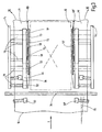
- eine Seitenansicht einer erfindungsgemäßen Längstrennschweißvor- richtung,
- Fig. 3
- eine Draufsicht auf ein erfindungsgemäßes Längstrennschweißsys- tem entlang einer Linie III-III in
Fig. 2 , und - Fig. 4
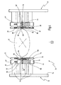
- einer Querschnittsansicht eines erfindungsgemäßen Längstrenn- schweißsystems entlang einer Linie IV-IV in
Fig. 2 .
- Fig. 1
- a schematic view of a Folienverpa- ckungsmaschine invention,
- Fig. 2
- a side view of a Längsegendschweißvor- direction invention,
- Fig. 3
- a plan view of an inventive longitudinal separation welding system along a line III-III in
Fig. 2 , and - Fig. 4
- a cross-sectional view of a longitudinal separation welding system according to the invention along a line IV-IV in
Fig. 2 ,
Das Packgut 12 wird von der Folienverpackungsmaschine 10 mit einer oberen Folienbahn 14, die von einer oberen Folienzuführung 15 abgewickelt wird, und einer unteren Folienbahn 16, die von einer unteren Folienzuführung 17 abgewickelt wird, eingehüllt. Diese Art der Einhellung entspricht dem Prinzip einer sog. Serienpackmaschine, so dass dementsprechend die vorliegende Erfindung am Beispiel einer als Serienpackmaschine ausgestalteten Folienverpackungsmaschine 10 erläutert wird.The packaged
Die obere Folienbahn 14 und die untere Folienbahn 16 laufen in einer Folienebene 18 zusammen. Das Packgut 12 fährt somit in die aufeinander zulaufende obere Folienbahn 14 und untere Folienbahn 16 ein, wobei die Folienbahnen 14, 16 zunächst einer Querstraffung unterzogen werden.The
Dazu ist eine Querstraffungsvorrichtung 20 vorgesehen. Die mögliche Ausgestaltung dieser Querstraffungsvorrichtung wird mit Blick auf die folgenden Figuren noch näher erläutert. Das umhüllte Packgut 12 mit den quer gestrafften Folienbahnen 14, 16 erreicht dann eine Quertrennschweißvorrichtung 22. Die Quertrennschweißvorrichtung 22 schweißt die Folienbahnen 14, 16 quer zu der Transportrichtung T zusammen und durchtrennt die Folienbahnen 14, 16 zumindest teilweise, so dass das Packgut 12 entlang der Schweißnaht keinen Kontakt mehr zu dem ihm vorhergehenden Packgut hat. Die in Transportrichtung T weisende Seite des Packguts 12 ist somit bereits verschweißt.For this purpose, a
Anschließend fährt das Packgut durch ein Längstrennschweißsystem 24, das dazu vorgesehen ist, die Folienbahnen 14, 16 seitlich des Packguts 12 zusammenzuschweißen und einen seitlichen Folienüberstand abzutrennen. Schließlich wird die entgegengesetzt zu der Transportrichtung T weisende Seite des Packguts 12 erneut von der Quertrennschweißvorrichtung 22 verschweißt und abgetrennt. Dieser Vorgang stellt dabei gleichzeitig die Abtrennung und Verschweißung der in die Transportrichtung T weisenden Seite eines nachfolgenden Packguts dar. Das Packgut 12 ist nun an allen vier Seiten verschweißt und beschnitten, so dass das Packgut 12 von einer Folienumhüllung komplett umgeben ist.Subsequently, the packaged goods passes through a longitudinal
Die Abfolge der Quertrennschweißvorrichtung 22, des Längstrennschweißsystems 24 und der Querstraffungsvorrichtung 20 ist lediglich beispielhaft in einer häufig auftretenden Konfiguration wiedergegeben. Die Abfolge dieser Einrichtungen kann auch anders sein, bspw. kann vorgesehen sein, die Quertrennschweißvorrichtung 22 nach dem Längstrennschweißsystem 24 anzuordnen. Auch können Elemente der Querstraffungsvorrichtung 20 zwischen oder in der Quertrennschweißvorrichtung 22 oder dem Längstrennschweißsystem 24 vorgesehen sein.The sequence of
In der Regel ist vorgesehen, dass sich dann ein Schrumpftunnel 26 anschließt, der auf eine bestimmte Temperatur erwärmt ist und die Folienbahnen 14, 16 auf das Packgut 12 aufschrumpft, so dass die Folienbahnen 14, 16 das Packgut 12 fest und ohne Spiel umschließen. Der Verpackungsvorgang ist dann abgeschlossen.In general, it is provided that then a
Das Vorhandensein eines Schrumpftunnels 26 hängt grundsätzlich von den an die Verpackung gestellten Anforderungen ab. Ein Schrumpftunnel 26 muss insbesondere bei Serienpackmaschinen nicht zwingend vorhanden sein.The presence of a
Des Weiteren weist die Folienverpackungsmaschine 10 in der Regel Verstelleinrichtungen 28 auf, um die Verpackungsmaschine 10 an Packgüter unterschiedlicher Breite, Länge und Höhe einstellen zu können. Auch die Geschwindigkeit des Verpackungsvorgangs kann mittels der Verstelleinrichtungen 28 eingestellt werden. Des Weiteren sind Möglichkeiten vorgesehen, die Verpackungsmaschine 10 auf unterschiedliche Folientypen, die bspw. in Dicke, Reißfestigkeit und Oberflächenbeschaffenheit unterschiedlich sein können, einzustellen.Furthermore, the
Letztlich ist in der Regel eine Folienrückführung 30 vorgesehen, die von dem Längstrennschweißsystem 24 abgetrenntes überschüssiges Folienmaterial sammelt, um es bspw. einem Recyclingprozess zuzuführen.Finally, a
Mit II ist ein Ausschnitt der Folienverpackungsmaschine 10 bezeichnet, der in
Um sicherzustellen, dass die Räder 32, 33 die Folienbahnen 14, 16 sicher einziehen und durch die aufgebrachte Querkraft die Folienbahnen 14, 16 nicht in den Räder 32, 33 verrutschen, weist bspw. das Rad 32 eine gummierte Oberfläche auf, wohingegen das Rad 33 eine gerändelte Oberfläche aufweist, die etwa aus einem Metall besteht. Die Oberfläche des Rads 33 drückt dann in die Oberfläche des Rads 32 ein, so dass ein rutschfestes Erfassen und Halten der Folienbahnen 14, 16 sichergestellt ist.In order to ensure that the
Selbstverständlich kann die Oberflächenbeschaffenheit der Räder 32, 33 auch umgekehrt sein, so dass das Rad 32 die Rändelung und das Rad 33 die gummierte Oberfläche aufweist.Of course, the surface finish of the
Die Räder 32, 33 stellen insbesondere eine optimale Querstraffung für den Quertrennschweißvorgang mittels der Quertrennschweißvorrichtung 22 sicher. Entsprechend ist in der Längstrennschweißvorrichtung 31 ein aus zwei Rädern 35, 36 bestehendes Räderpaar 37 vorgesehen, das dieselbe Funktion wie das erste Räderpaar 34 mit den Rädern 32, 33 erfüllt. Das Räderpaar 37 stellt so eine optimale Querstraffung der Folienbahnen 14, 16 für den Längstrennschweißvorgang bereit.In particular, the
Der Quertrennschweißvorgang mittels der Quertrennschweißvorrichtung 22 wird von einem Oberstempel 39 und einem Unterstempel 40 bewirkt. Der Oberstempel 39 weist ein Schweißmesser auf, das gegen den Unterstempel 40 gedrückt wird und die Folienbahnen 14, 16 miteinander verschweißt und diese durchtrennt. Dazu werden der Oberstempel 39 und der Unterstempel 40 aufeinander zubewegt, so dass sie sich im Bereich der Folienebene 18 treffen. Der Schweißvorgang wird in der Regel mittels einer erhitzten Schneidklinge erzielt. Als Alternative zu der Schneidklinge kann auch ein beheizter Draht verwendet werden. Der Draht wird dabei nicht ständig auf einer hohen Temperatur gehalten, sondern nur impulsbeheizt. Der Draht kann sich dann bei geschlossenen Stempeln 39, 40 wieder abkühlen, was zu einem besseren Schweißergebnis führen kann.The cross-cutting welding operation by means of the
Zum Transport und zur Fixierung der Folienbahnen 14, 16 sind in der Längstrennschweißvorrichtung zwei Endlosriemen 42, 44 vorgesehen, die die Folienbahnen 14, 16 in der Folienebene 18 zwischen sich einziehen und klemmen und die Folienbahnen 14, 16 und das Packgut 12 fördern. Jeweils ein Endlosriemen 42, 44 ist somit auf jeder Seite der Folienebene 18 angeordnet.For transporting and fixing the
Der Endlosriemen 42 läuft um drei Rollen 46, 48, 49 um. Der Endlosriemen 44 läuft um drei Rollen 51, 53, 54 um.The
Die Laufbahnen der Rollen 46 und 47 sowie 51 und 52 weisen denselben Durchmesser auf. Im Bereich den Endlosriemens 42 weisen die Rollen 47 und 52 jedoch bereits wieder einen geringeren Durchmesser auf, so dass die Endlosriemen 42, 44 nicht über die Rollen 47 und 52 laufen.The raceways of the
An der Stelle, an der die Folienbahnen 14, 16 von den Endlosriemen 42, 44 zwischen sich eingezogen werden, befinden sich die Rollen 48 und 53. Jeweils vertikal versetzt zu den Rollen 48 und 53 sind Rollen 49 bzw. 54 vorgesehen. Die Rollen 48 und 49 bzw. 53 und 54 sind relativ zueinander verschiebbar, bspw. indem die Rollen 49 und 54 in einem sich vertikal erstreckenden Langloch (nicht dargestellt) befestigt sind. Auf diese Weise kann die Spannung der Endlosriemen 42, 44 reguliert werden, insbesondere kann so auch ein leichtes Austauschen der Endlosriemen 42, 44 erreicht werden.At the point where the
Die Folienbahnen 14, 16 werden entlang der Folienebene 18 von den Endlosriemen 42, 44 gefördert und durch ein Schweißmesser 56 geführt. In dem dargestellten Beispiel ist das Schweißmesser 56 ein feststehendes Schweißmesser, es kann grundsätzlich aber auch ein rotierendes Schweißmesser vorgesehen sein. Das Schweißmesser 56 wird mit einer geeigneten Vorrichtung erwärmt, so dass das Schweißmesser 56 die Folienbahnen 14, 16 durchtrennt und an ihrem Ende verschmelzt bzw. verschweißt.The
Um dem Schweißmesser 56 die Folienbahnen 14, 16 möglichst faltenfrei zuzuführen, ist vor dem Schweißmesser 56 eine Spannrolle 58 vorgesehen, die auf der dem Schweißmesser 56 gegenüberliegenden Seite der Folienebene 18 angeordnet ist und diese durchdringt. Durch die Spannrolle 58 werden die Folienbahnen 14, 16 kurzzeitig angehoben und weitestgehend faltenfrei gezogen. Selbst wenn eine Falte nicht durch die Spannrolle 58 entfernt werden könnte, wird so zumindest sichergestellt, dass auch die jeweils andere Folienbahn 14, 16 sich entsprechend in die Falte legt, so dass die Folienbahnen 14, 16 ohne Lufteinschlüsse aufeinanderliegen, wenn sie verschweißt werden. So wird die Qualität einer hochwertigen Schweißnaht sichergestellt.In order to supply the
Des Weiteren ist eine Stützschiene 60 vorgesehen, die dazu vorgesehen ist, die Folienbahnen 14, 16 im Bereich des Schweißmessers 56 fest und glatt aufeinander zu pressen. Die Anpresskraft der Stützschiene 60 wird mittels geeigneter Federelemente 62, 64 erzeugt. Diese drücken die Stützschiene 60 auf eine gegenüberliegende Stützschiene 66. Die Stützschienen 60, 66 weisen dabei eine in
Bei der in diesem Ausführungsbeispiel beschriebenen Folienverpackungsmaschine handelt es sich um eine sog. Serienpackmaschine. Entsprechend werden zwei Längsseiten 69 des Packguts 12 mittels einer entsprechenden Längstrennschweißvorrichtung 31 verschweißt. Somit weist das Längstrennschweißsystem 24 zwei Längstrennschweißvorrichtungen 31 auf, die einander gegenüberliegend angeordnet und spiegelbildlich aufgebaut sind. Folglich wird lediglich eine der beiden Längstrennschweißvorrichtungen 31 näher erläutert, Bezugszeichen der gegenüberliegenden Längstrennschweißvorrichtung 31 sind mit einem Strich trunkiert.The film packaging machine described in this embodiment is a so-called series packing machine. Accordingly, two
Der Ansicht in
Das Schweißmesser 56 durchtrennt an der jeweiligen Längsseiten 69 die Folienbahnen 14, 16. Dadurch wird ein Abfallstreifen 71 erzeugt, der von den Endlosriemen 42, 44 gefördert wird. Dieser Abfallstreifen 71 wird der Folienrückführung 30 zugeführt.The
Parallel zu dem Endlosriemen 44 ist ein zweiter Endlosriemen 72 auf der dem Packgut 12 zugewandten Seite des Schweißmessers 56 angeordnet. Dieser Endlosriemen 72 ist deutlich schmaler als der Endlosriemen 44 ausgebildet, insbesondere kann er eine Breite von etwa 3 mm aufweisen.Parallel to the
Somit werden die Folienbahnen 14, 16 im Bereich des Schweißmessers 56 zu beiden Seiten des Schweißmessers zusammengedrückt, geführt und transportiert.Thus, the
Der Endlosriemen 72 läuft über eine Hilfsrolle 73 und die Rolle 52. Die Hilfsrolle 73 verläuft dabei konzentrisch zu der Rolle 51.The
Des Weiteren ist ein Halteelement 74 vorgesehen, um die Rollen 51, 73, 52, 53, 54 und die entsprechend auf der gegenüberliegenden Seite der Folienebene 18 vorhandenen Rollenelemente zu halten.Furthermore, a holding
Der Endlosriemen 44 und der Endlosriemen 72 bilden zwischen sich einen Längsspalt 75 aus, in dem das Schweißmesser 56 und die Spannrolle 58 angeordnet sind. Von dem Halteelement 74 aus erstrecken sich mehrere Haltewellen 76 (nicht einzeln nummeriert), die jeweils entsprechende Längen aufweisen, um die Rollenelemente 51, 52, 53, 54, 73, das Schweißmesser 56 und die Spannrolle 58 in entsprechenden, den Längsspalt 75 ausbildenden Abständen zueinander zu stützen.The
Abgebildet in
In Bezug auf die Endlosriemen 42, 44 wird in dieser Ansicht erkennbar, dass diese auf den Rollen 46 bzw. 51 einer entsprechenden Nut 77 bzw. 77' geführt sind. Die Nut weist ein U-förmiges Querschnittsprofil auf, so dass die Schenkel des U eine seitliche Führung 78 bzw. 78' auf beiden Seiten des entsprechenden Riemens 42, 44 bereitstellt. Auf diese Weise wird verhindert, dass der entsprechende Endlosriemen 42, 44 von der jeweiligen Rollenführung seitlich abrutschen kann.With respect to the
Eine erfindungsgemäße Verbesserung liegt hierbei bezüglich des schmaleren, unmittelbar am Packgut 12 anliegenden oberen Endlosriemens 72 bzw. eines entsprechenden unteren Endlosriemens 79 vor.An improvement according to the invention is in this case with regard to the narrower upper
Die Verbesserung wird zunächst für den auf der Seite des Schweißmessers 56 der Folienebene 18 angeordneten Endlosriemens 72 beschrieben. Dieser wird wie auch bei dem entsprechenden breiteren parallelen Endlosriemen 42 von einer Stützschiene 80 auf die Folienebene 18 gedrückt. Die Stützschiene 80 ist dafür mittels eines Federelements 82 gespannt. Auch die Stützschiene 80 weist eine Nut 83 auf, in der der Endlosriemen 72 geführt ist. Die Nut 83 weist ebenfalls einen U-förmigen Querschnitt auf. Eine Seitenwand 84, die benachbart zu dem Schweißmesser 56, d.h. auf der dem Packgut 12 abgewandten Seite der Nut 83 liegt, weist im Bereich des Schweißmessers 56 die Aussparung 68 auf. In der in
Gleichzeitig wird es auf diese Weise möglich, wertvolle Millimeter bei der Positionierung der Schweißnaht so nah wie möglich an dem Packgut 12 zu gewinnen und den Folienüberstand zu minimieren.At the same time it is possible in this way to gain valuable millimeters in the positioning of the weld as close as possible to the packaged
Insbesondere wenn kein Schrumpftunnel 26 verwendet wird, wie dies in einer Serienpackmaschine häufig der Fall ist, führt es dazu, dass das Packgut 12 innerhalb der Folienverpackung Spiel hat, was vermieden werden soll und durch die Erfindung im Wesentlichen vermieden wird.In particular, if no
Ragt das Schweißmesser 56 durch die Folienebene 18 über den Endlosriemen 79 nach unten heraus, ist auch dort die Aussparung 68 fortzusetzen. Der Endlosriemen 79 ist entsprechend in einer Nut 85 geführt, die Aussparung 68 ist dann in einer Seitenwand 86 der Nut 85 vorgesehen. Entsprechend weist eine Stützschiene 87 für den unteren Endlosriemen 79 eine Aussparung 88 auf, die im Bereich des Schweißmessers 56 der Nut 85 einen L-förmigen Querschnitt verleiht, so dass in dem Bereich des Schweißmessers 56 ebenfalls keine Seitenwand 86 vorhanden ist. Die Aussparung 88 setzt so die Aussparung 68 für das Schweißmesser 56 über die Folienebene 18 hinaus fort.If the
Claims (15)
- Longitudinal separation welding device (31) for the longitudinal welding of a longitudinal side (69) of an upper (14) and a lower (16) film web, the longitudinal separation welding device (31) having at least one first pair of endless belts (72, 79) which run in each case over at least two rollers (47, 46; 51, 52) and which draw the upper (14) and lower (16) film web in between themselves and guide them in a film plane (18), a welding knife (56) being arranged parallel to the at least one first pair of endless belts (72, 79) on a first side of the film plane (18), an endless belt (72), arranged on the first side of the film plane (18), of the first pair of endless belts (72, 79) being guided on the film plane (18) in a groove (83) of a supporting rail (80), characterized in that a side wall (84) of the groove (83) has a clearance (68) in which the welding knife (56) is arranged directly on the endless belt (72).
- Longitudinal separation welding device according to Claim 1, characterized in that the upper (14) and lower (16) film envelop a packageable article (12) between themselves, and the side wall (84) is a side wall facing away from the packageable article (12).
- Longitudinal separation welding device according to Claim 1 or 2, characterized in that the groove (83) has a U-shaped cross section and the side wall (84) forms one leg of the U.
- Longitudinal separation welding device according to one of Claims 1 to 3, characterized in that a second pair of endless belts (42, 44) is provided, which run in each case over at least two rollers (46, 48, 49; 51, 53, 54) and which draw the upper (14) and lower (16) film web between themselves and guide them in the film plane (18), a longitudinal gap (75) in which the welding knife (56) is arranged, being formed between the first pair of endless belts (42, 44) and the second pair of endless belts (72, 79).
- Longitudinal separation welding device according to one of Claims 1 to 4, characterized in that the width of the first pair of endless belts (72, 79) is smaller than the width of the second pair of endless belts (42, 44).
- Longitudinal separation welding device according to one of Claims 1 to 5, characterized in that the width of the first pair of endless belts (72, 79) amounts to 2.5 to 6 mm.
- Longitudinal separation welding device according to one of Claims 1 to 6, characterized in that the first pair of endless belts (72, 79) runs in each case over at least two rollers (47, 46; 51, 52), two of the at least two rollers (47, 46; 51, 52) being displaceable in relation to one another in an operating state.
- Longitudinal separation welding device according to one of Claims 4 to 7, characterized in that the second pair of endless belts (42, 49) runs in each case over at least three rollers (46, 48, 49; 51, 53, 54), two (48, 49; 53, 54) of the at least three rollers (46, 48, 49; 51, 53, 54) being arranged one above the other and being displaceable in relation to one another in an operating state.
- Longitudinal separation welding device according to one of Claims 1 to 8, characterized in that a tension roller (58) is arranged in the longitudinal gap (75), upstream of the welding knife (56) on that side of the film plane (18) which lies opposite the first side, the tensioning roller (58) being supported resiliently and penetrating through the film plane (18).
- Longitudinal separation welding device according to one of Claims 1 to 9, characterized in that an endless belt (79) of the first pair of endless belts (72, 79), the said endless belt being arranged on that side of the film plane (18) which lies opposite the first side, is also guided on the film plane (18) in a groove (85) of a supporting rail (87), and a side wall (86) of the groove (85) has a clearance (88) in which the welding knife (56) is at least partially arranged.
- Longitudinal separation welding system (24), characterized by two longitudinal separation welding devices (31) according to one of Claims 1 to 10 for the longitudinal welding of both longitudinal sides (69) of the upper (14) and lower (16) film web.
- Longitudinal separation welding system according to Claim 11, characterized in that the two longitudinal separation welding devices (31) are arranged opposite one another and are designed mirror-symmetrically with respect to a film transport direction (T) of the upper (14) and lower (16) film.
- Film packaging machine (10), there being provided upstream of the longitudinal separation welding device (31) with respect to a film transport direction (T) a transverse separation welding device (22) which at least partially welds and separates the upper (14) and lower (16) film web, there being arranged on at least one longitudinal side (69) of the upper (14) and lower (16) film web at least one pair of wheels (32, 34; 35, 36), on which the rolling direction in relation to the transport direction (T) runs outwards at an angle (70), one wheel of the at least one pair of wheels (32, 34; 35, 36) having a rubberized surface, and another wheel of the at least one pair of wheels (32, 34; 35, 36) having a knurled surface, characterized by a longitudinal separation welding device (31) according to one of Claims 1 to 10.
- Film packaging machine according to Claim 13, characterized in that at least one pair of wheels (32, 34; 35, 36) is arranged in each case on both longitudinal sides (69) of the upper (14) and lower (16) film web, the wheels which have a rubberized surface lying opposite one another, and the wheels which have a knurled surface lying opposite one another.
- Film packaging machine according to Claim 13 or 14, characterized in that the at least one pair of wheels (32, 34; 35, 36) is arranged upstream of the transverse separation welding device (22) with respect to a film transport direction (T).
Applications Claiming Priority (1)
| Application Number | Priority Date | Filing Date | Title |
|---|---|---|---|
| DE102009059049A DE102009059049A1 (en) | 2009-12-14 | 2009-12-14 | Longitudinal part welding device for a film packaging machine |
Publications (2)
| Publication Number | Publication Date |
|---|---|
| EP2332843A1 EP2332843A1 (en) | 2011-06-15 |
| EP2332843B1 true EP2332843B1 (en) | 2012-06-20 |
Family
ID=43587354
Family Applications (1)
| Application Number | Title | Priority Date | Filing Date |
|---|---|---|---|
| EP10193768A Not-in-force EP2332843B1 (en) | 2009-12-14 | 2010-12-06 | Longitudinal welding device for a film packaging machine |
Country Status (2)
| Country | Link |
|---|---|
| EP (1) | EP2332843B1 (en) |
| DE (1) | DE102009059049A1 (en) |
Cited By (1)
| Publication number | Priority date | Publication date | Assignee | Title |
|---|---|---|---|---|
| DE102015116294A1 (en) | 2015-09-25 | 2017-03-30 | Beck Packautomaten Gmbh & Co. Kg | Improved longitudinal separating welding device, longitudinal separating welding system and film wrapping machine |
Families Citing this family (2)
| Publication number | Priority date | Publication date | Assignee | Title |
|---|---|---|---|---|
| DE102015122560A1 (en) | 2015-12-22 | 2017-06-22 | Beck Packautomaten Gmbh + Co Kg | Longitudinal part welding device for a film packaging machine, film packaging machine and method |
| DE102016217896A1 (en) | 2016-09-19 | 2018-03-22 | Krones Aktiengesellschaft | Device and method for the production of containers with carrying handles |
Family Cites Families (12)
| Publication number | Priority date | Publication date | Assignee | Title |
|---|---|---|---|---|
| US2715024A (en) * | 1951-03-07 | 1955-08-09 | Johnson & Johnson | Strip feeding device |
| US2947057A (en) * | 1956-02-03 | 1960-08-02 | Plainfield Patents Corp | Flexible web reeling and guiding mechanisms |
| US3142608A (en) * | 1960-08-22 | 1964-07-28 | Techtmann Ind Inc | Bag and wrapper sealing and cutoff mechanism |
| GB1027626A (en) * | 1962-01-26 | 1966-04-27 | Halley & Sons Ltd James | Improvements relating to the feed of webs of material |
| DE2751118C2 (en) * | 1977-11-16 | 1979-10-18 | Beck, Hans, 7440 Nuertingen | Separation welding device for sheets that are pushed forward and stacked on top of one another |
| IT8021194V0 (en) * | 1980-03-17 | 1980-03-17 | Leptons Italia Srl | PAPER HANDLING DEVICE FOR OVERPRINTERS OF LABELS OR SIMILAR. |
| DE19905888A1 (en) | 1999-02-11 | 2000-08-17 | Kallfass Gmbh | Welding device for weldable foils or the like |
| DE10021470B4 (en) | 2000-05-04 | 2004-12-09 | Werner Diez | Tubular bag packaging machine with transverse extenders |
| US20060167445A1 (en) * | 2002-08-27 | 2006-07-27 | Gal Shafirstein | Selective conductive interstitial thermal therapy device |
| DE102005033775B4 (en) | 2005-07-15 | 2008-12-11 | Beck Packautomaten Gmbh & Co. | Device for transverse tightening of film webs |
| US20070157554A1 (en) * | 2005-12-19 | 2007-07-12 | Liao Benker P | Plastic film sealing blade |
| DE102006042822B3 (en) | 2006-09-08 | 2008-01-31 | Beck Packautomaten Gmbh & Co. | Longitudinal welding device for sheeting lying on each other for use in sheet packing machine, has belt pulley which is arranged in longitudinal slot in transport direction in front of welding cutter |
-
2009
- 2009-12-14 DE DE102009059049A patent/DE102009059049A1/en not_active Withdrawn
-
2010
- 2010-12-06 EP EP10193768A patent/EP2332843B1/en not_active Not-in-force
Cited By (1)
| Publication number | Priority date | Publication date | Assignee | Title |
|---|---|---|---|---|
| DE102015116294A1 (en) | 2015-09-25 | 2017-03-30 | Beck Packautomaten Gmbh & Co. Kg | Improved longitudinal separating welding device, longitudinal separating welding system and film wrapping machine |
Also Published As
| Publication number | Publication date |
|---|---|
| DE102009059049A1 (en) | 2011-06-16 |
| EP2332843A1 (en) | 2011-06-15 |
Similar Documents
| Publication | Publication Date | Title |
|---|---|---|
| DE102017207247A1 (en) | Device for sealing a packaging | |
| EP2931495B1 (en) | Longitudinal sealing device | |
| EP2332843B1 (en) | Longitudinal welding device for a film packaging machine | |
| DE102006001594A1 (en) | Packaged goods pieces wrapping method, involves adjusting breadth of each packaged goods piece and welding opened sides of foil covers at longitudinal sides of packaged goods pieces | |
| EP3885274A2 (en) | Packaging machine and method for packaging a product with packaging produced from an upper paper sheet and a lower paper sheet | |
| DE102012103352B4 (en) | Packaging machine with revolving cross-cutting device | |
| DE102009060342A1 (en) | Packaging machine for e.g. packaged goods, has transport device movable relative to another transport device, where movement of lower stamp is coupled with movement of latter transport device relative to former transport device | |
| EP3757046B1 (en) | Device and method for joining two sheets of material each running from a reel | |
| EP2112069B1 (en) | Method and device for packaging portioned products in a wrapper | |
| EP2336033B1 (en) | Method and device for wrapping a stack of goods with a film | |
| EP2364914B1 (en) | Width-adjustable lower punch | |
| DE102015116294A1 (en) | Improved longitudinal separating welding device, longitudinal separating welding system and film wrapping machine | |
| DE102020106030B4 (en) | Longitudinal separation welding device for a packaging machine and method for packaging a packaged goods with an outer packaging produced from an upper paper web and a lower paper web | |
| DE3409702C2 (en) | ||
| EP2345586B1 (en) | Width-variable packaging machine | |
| DE19817870B4 (en) | Winding device for a web | |
| EP3715266A1 (en) | Film packaging machine and method for packaging a packed product | |
| EP0681957A1 (en) | Method and device for wrapping cubolds, especially bales of insulating material with wrapping material | |
| EP1857366B1 (en) | Device for packing objects simultaneously | |
| DE102022112633A1 (en) | Packaging machine and method for packaging objects in a paper packaging | |
| EP0410226A2 (en) | Apparatus for adhesive-free joining of layers of paper, thin carton, or similar materials | |
| DE102010018381B4 (en) | Device and method for film welding flat products | |
| DE2412676B2 (en) | TOOL FOR WELDING PLASTIC FILMS | |
| EP3181478A1 (en) | Packaging unit with extension film envelope | |
| DE7409205U (en) | Tool for welding plastic foils enveloping packaging objects |
Legal Events
| Date | Code | Title | Description |
|---|---|---|---|
| PUAI | Public reference made under article 153(3) epc to a published international application that has entered the european phase |
Free format text: ORIGINAL CODE: 0009012 |
|
| AK | Designated contracting states |
Kind code of ref document: A1 Designated state(s): AL AT BE BG CH CY CZ DE DK EE ES FI FR GB GR HR HU IE IS IT LI LT LU LV MC MK MT NL NO PL PT RO RS SE SI SK SM TR |
|
| AX | Request for extension of the european patent |
Extension state: BA ME |
|
| 17P | Request for examination filed |
Effective date: 20110826 |
|
| GRAP | Despatch of communication of intention to grant a patent |
Free format text: ORIGINAL CODE: EPIDOSNIGR1 |
|
| RIC1 | Information provided on ipc code assigned before grant |
Ipc: B65H 23/025 20060101ALI20111020BHEP Ipc: B65B 51/26 20060101AFI20111020BHEP Ipc: B29C 65/74 20060101ALI20111020BHEP |
|
| GRAS | Grant fee paid |
Free format text: ORIGINAL CODE: EPIDOSNIGR3 |
|
| GRAA | (expected) grant |
Free format text: ORIGINAL CODE: 0009210 |
|
| AK | Designated contracting states |
Kind code of ref document: B1 Designated state(s): AL AT BE BG CH CY CZ DE DK EE ES FI FR GB GR HR HU IE IS IT LI LT LU LV MC MK MT NL NO PL PT RO RS SE SI SK SM TR |
|
| REG | Reference to a national code |
Ref country code: GB Ref legal event code: FG4D Free format text: NOT ENGLISH |
|
| REG | Reference to a national code |
Ref country code: CH Ref legal event code: EP |
|
| REG | Reference to a national code |
Ref country code: AT Ref legal event code: REF Ref document number: 562930 Country of ref document: AT Kind code of ref document: T Effective date: 20120715 |
|
| REG | Reference to a national code |
Ref country code: IE Ref legal event code: FG4D Free format text: LANGUAGE OF EP DOCUMENT: GERMAN |
|
| REG | Reference to a national code |
Ref country code: DE Ref legal event code: R096 Ref document number: 502010000913 Country of ref document: DE Effective date: 20120816 |
|
| PG25 | Lapsed in a contracting state [announced via postgrant information from national office to epo] |
Ref country code: LT Free format text: LAPSE BECAUSE OF FAILURE TO SUBMIT A TRANSLATION OF THE DESCRIPTION OR TO PAY THE FEE WITHIN THE PRESCRIBED TIME-LIMIT Effective date: 20120620 Ref country code: RS Free format text: LAPSE BECAUSE OF FAILURE TO SUBMIT A TRANSLATION OF THE DESCRIPTION OR TO PAY THE FEE WITHIN THE PRESCRIBED TIME-LIMIT Effective date: 20120620 Ref country code: SE Free format text: LAPSE BECAUSE OF FAILURE TO SUBMIT A TRANSLATION OF THE DESCRIPTION OR TO PAY THE FEE WITHIN THE PRESCRIBED TIME-LIMIT Effective date: 20120620 Ref country code: FI Free format text: LAPSE BECAUSE OF FAILURE TO SUBMIT A TRANSLATION OF THE DESCRIPTION OR TO PAY THE FEE WITHIN THE PRESCRIBED TIME-LIMIT Effective date: 20120620 Ref country code: NO Free format text: LAPSE BECAUSE OF FAILURE TO SUBMIT A TRANSLATION OF THE DESCRIPTION OR TO PAY THE FEE WITHIN THE PRESCRIBED TIME-LIMIT Effective date: 20120920 |
|
| REG | Reference to a national code |
Ref country code: NL Ref legal event code: VDEP Effective date: 20120620 |
|
| REG | Reference to a national code |
Ref country code: LT Ref legal event code: MG4D Effective date: 20120620 |
|
| PG25 | Lapsed in a contracting state [announced via postgrant information from national office to epo] |
Ref country code: HR Free format text: LAPSE BECAUSE OF FAILURE TO SUBMIT A TRANSLATION OF THE DESCRIPTION OR TO PAY THE FEE WITHIN THE PRESCRIBED TIME-LIMIT Effective date: 20120620 Ref country code: SI Free format text: LAPSE BECAUSE OF FAILURE TO SUBMIT A TRANSLATION OF THE DESCRIPTION OR TO PAY THE FEE WITHIN THE PRESCRIBED TIME-LIMIT Effective date: 20120620 Ref country code: GR Free format text: LAPSE BECAUSE OF FAILURE TO SUBMIT A TRANSLATION OF THE DESCRIPTION OR TO PAY THE FEE WITHIN THE PRESCRIBED TIME-LIMIT Effective date: 20120921 Ref country code: LV Free format text: LAPSE BECAUSE OF FAILURE TO SUBMIT A TRANSLATION OF THE DESCRIPTION OR TO PAY THE FEE WITHIN THE PRESCRIBED TIME-LIMIT Effective date: 20120620 |
|
| PG25 | Lapsed in a contracting state [announced via postgrant information from national office to epo] |
Ref country code: SK Free format text: LAPSE BECAUSE OF FAILURE TO SUBMIT A TRANSLATION OF THE DESCRIPTION OR TO PAY THE FEE WITHIN THE PRESCRIBED TIME-LIMIT Effective date: 20120620 Ref country code: CZ Free format text: LAPSE BECAUSE OF FAILURE TO SUBMIT A TRANSLATION OF THE DESCRIPTION OR TO PAY THE FEE WITHIN THE PRESCRIBED TIME-LIMIT Effective date: 20120620 Ref country code: EE Free format text: LAPSE BECAUSE OF FAILURE TO SUBMIT A TRANSLATION OF THE DESCRIPTION OR TO PAY THE FEE WITHIN THE PRESCRIBED TIME-LIMIT Effective date: 20120620 Ref country code: RO Free format text: LAPSE BECAUSE OF FAILURE TO SUBMIT A TRANSLATION OF THE DESCRIPTION OR TO PAY THE FEE WITHIN THE PRESCRIBED TIME-LIMIT Effective date: 20120620 Ref country code: CY Free format text: LAPSE BECAUSE OF FAILURE TO SUBMIT A TRANSLATION OF THE DESCRIPTION OR TO PAY THE FEE WITHIN THE PRESCRIBED TIME-LIMIT Effective date: 20120620 Ref country code: IS Free format text: LAPSE BECAUSE OF FAILURE TO SUBMIT A TRANSLATION OF THE DESCRIPTION OR TO PAY THE FEE WITHIN THE PRESCRIBED TIME-LIMIT Effective date: 20121020 |
|
| PG25 | Lapsed in a contracting state [announced via postgrant information from national office to epo] |
Ref country code: PL Free format text: LAPSE BECAUSE OF FAILURE TO SUBMIT A TRANSLATION OF THE DESCRIPTION OR TO PAY THE FEE WITHIN THE PRESCRIBED TIME-LIMIT Effective date: 20120620 Ref country code: IT Free format text: LAPSE BECAUSE OF FAILURE TO SUBMIT A TRANSLATION OF THE DESCRIPTION OR TO PAY THE FEE WITHIN THE PRESCRIBED TIME-LIMIT Effective date: 20120620 Ref country code: PT Free format text: LAPSE BECAUSE OF FAILURE TO SUBMIT A TRANSLATION OF THE DESCRIPTION OR TO PAY THE FEE WITHIN THE PRESCRIBED TIME-LIMIT Effective date: 20121022 |
|
| PG25 | Lapsed in a contracting state [announced via postgrant information from national office to epo] |
Ref country code: NL Free format text: LAPSE BECAUSE OF FAILURE TO SUBMIT A TRANSLATION OF THE DESCRIPTION OR TO PAY THE FEE WITHIN THE PRESCRIBED TIME-LIMIT Effective date: 20120620 |
|
| PLBE | No opposition filed within time limit |
Free format text: ORIGINAL CODE: 0009261 |
|
| STAA | Information on the status of an ep patent application or granted ep patent |
Free format text: STATUS: NO OPPOSITION FILED WITHIN TIME LIMIT |
|
| PG25 | Lapsed in a contracting state [announced via postgrant information from national office to epo] |
Ref country code: DK Free format text: LAPSE BECAUSE OF FAILURE TO SUBMIT A TRANSLATION OF THE DESCRIPTION OR TO PAY THE FEE WITHIN THE PRESCRIBED TIME-LIMIT Effective date: 20120620 Ref country code: ES Free format text: LAPSE BECAUSE OF FAILURE TO SUBMIT A TRANSLATION OF THE DESCRIPTION OR TO PAY THE FEE WITHIN THE PRESCRIBED TIME-LIMIT Effective date: 20121001 |
|
| 26N | No opposition filed |
Effective date: 20130321 |
|
| BERE | Be: lapsed |
Owner name: BECK PACKAUTOMATEN G.M.B.H. & CO. KG Effective date: 20121231 |
|
| REG | Reference to a national code |
Ref country code: DE Ref legal event code: R097 Ref document number: 502010000913 Country of ref document: DE Effective date: 20130321 |
|
| PG25 | Lapsed in a contracting state [announced via postgrant information from national office to epo] |
Ref country code: MC Free format text: LAPSE BECAUSE OF NON-PAYMENT OF DUE FEES Effective date: 20121231 Ref country code: BG Free format text: LAPSE BECAUSE OF FAILURE TO SUBMIT A TRANSLATION OF THE DESCRIPTION OR TO PAY THE FEE WITHIN THE PRESCRIBED TIME-LIMIT Effective date: 20120920 |
|
| REG | Reference to a national code |
Ref country code: IE Ref legal event code: MM4A |
|
| REG | Reference to a national code |
Ref country code: FR Ref legal event code: ST Effective date: 20130830 |
|
| PG25 | Lapsed in a contracting state [announced via postgrant information from national office to epo] |
Ref country code: BE Free format text: LAPSE BECAUSE OF NON-PAYMENT OF DUE FEES Effective date: 20121231 |
|
| PG25 | Lapsed in a contracting state [announced via postgrant information from national office to epo] |
Ref country code: IE Free format text: LAPSE BECAUSE OF NON-PAYMENT OF DUE FEES Effective date: 20121206 |
|
| PG25 | Lapsed in a contracting state [announced via postgrant information from national office to epo] |
Ref country code: MT Free format text: LAPSE BECAUSE OF FAILURE TO SUBMIT A TRANSLATION OF THE DESCRIPTION OR TO PAY THE FEE WITHIN THE PRESCRIBED TIME-LIMIT Effective date: 20120620 Ref country code: AL Free format text: LAPSE BECAUSE OF FAILURE TO SUBMIT A TRANSLATION OF THE DESCRIPTION OR TO PAY THE FEE WITHIN THE PRESCRIBED TIME-LIMIT Effective date: 20120620 Ref country code: FR Free format text: LAPSE BECAUSE OF NON-PAYMENT OF DUE FEES Effective date: 20130102 |
|
| PG25 | Lapsed in a contracting state [announced via postgrant information from national office to epo] |
Ref country code: TR Free format text: LAPSE BECAUSE OF FAILURE TO SUBMIT A TRANSLATION OF THE DESCRIPTION OR TO PAY THE FEE WITHIN THE PRESCRIBED TIME-LIMIT Effective date: 20120620 |
|
| PG25 | Lapsed in a contracting state [announced via postgrant information from national office to epo] |
Ref country code: LU Free format text: LAPSE BECAUSE OF NON-PAYMENT OF DUE FEES Effective date: 20121206 Ref country code: SM Free format text: LAPSE BECAUSE OF FAILURE TO SUBMIT A TRANSLATION OF THE DESCRIPTION OR TO PAY THE FEE WITHIN THE PRESCRIBED TIME-LIMIT Effective date: 20120620 |
|
| PG25 | Lapsed in a contracting state [announced via postgrant information from national office to epo] |
Ref country code: HU Free format text: LAPSE BECAUSE OF FAILURE TO SUBMIT A TRANSLATION OF THE DESCRIPTION OR TO PAY THE FEE WITHIN THE PRESCRIBED TIME-LIMIT Effective date: 20101206 |
|
| PG25 | Lapsed in a contracting state [announced via postgrant information from national office to epo] |
Ref country code: MK Free format text: LAPSE BECAUSE OF FAILURE TO SUBMIT A TRANSLATION OF THE DESCRIPTION OR TO PAY THE FEE WITHIN THE PRESCRIBED TIME-LIMIT Effective date: 20120620 |
|
| REG | Reference to a national code |
Ref country code: CH Ref legal event code: PL |
|
| GBPC | Gb: european patent ceased through non-payment of renewal fee |
Effective date: 20141206 |
|
| PG25 | Lapsed in a contracting state [announced via postgrant information from national office to epo] |
Ref country code: LI Free format text: LAPSE BECAUSE OF NON-PAYMENT OF DUE FEES Effective date: 20141231 Ref country code: GB Free format text: LAPSE BECAUSE OF NON-PAYMENT OF DUE FEES Effective date: 20141206 Ref country code: CH Free format text: LAPSE BECAUSE OF NON-PAYMENT OF DUE FEES Effective date: 20141231 |
|
| PGFP | Annual fee paid to national office [announced via postgrant information from national office to epo] |
Ref country code: DE Payment date: 20160203 Year of fee payment: 6 |
|
| REG | Reference to a national code |
Ref country code: AT Ref legal event code: MM01 Ref document number: 562930 Country of ref document: AT Kind code of ref document: T Effective date: 20151206 |
|
| PG25 | Lapsed in a contracting state [announced via postgrant information from national office to epo] |
Ref country code: AT Free format text: LAPSE BECAUSE OF NON-PAYMENT OF DUE FEES Effective date: 20151206 |
|
| REG | Reference to a national code |
Ref country code: DE Ref legal event code: R119 Ref document number: 502010000913 Country of ref document: DE |
|
| PG25 | Lapsed in a contracting state [announced via postgrant information from national office to epo] |
Ref country code: DE Free format text: LAPSE BECAUSE OF NON-PAYMENT OF DUE FEES Effective date: 20170701 |