EP2332830A2 - Aircraft reaction link - Google Patents
Aircraft reaction link Download PDFInfo
- Publication number
- EP2332830A2 EP2332830A2 EP10192687A EP10192687A EP2332830A2 EP 2332830 A2 EP2332830 A2 EP 2332830A2 EP 10192687 A EP10192687 A EP 10192687A EP 10192687 A EP10192687 A EP 10192687A EP 2332830 A2 EP2332830 A2 EP 2332830A2
- Authority
- EP
- European Patent Office
- Prior art keywords
- pair
- reaction link
- linear portions
- metal frame
- frame
- Prior art date
- Legal status (The legal status is an assumption and is not a legal conclusion. Google has not performed a legal analysis and makes no representation as to the accuracy of the status listed.)
- Granted
Links
Images





Classifications
-
- B—PERFORMING OPERATIONS; TRANSPORTING
- B64—AIRCRAFT; AVIATION; COSMONAUTICS
- B64C—AEROPLANES; HELICOPTERS
- B64C13/00—Control systems or transmitting systems for actuating flying-control surfaces, lift-increasing flaps, air brakes, or spoilers
- B64C13/24—Transmitting means
-
- Y—GENERAL TAGGING OF NEW TECHNOLOGICAL DEVELOPMENTS; GENERAL TAGGING OF CROSS-SECTIONAL TECHNOLOGIES SPANNING OVER SEVERAL SECTIONS OF THE IPC; TECHNICAL SUBJECTS COVERED BY FORMER USPC CROSS-REFERENCE ART COLLECTIONS [XRACs] AND DIGESTS
- Y02—TECHNOLOGIES OR APPLICATIONS FOR MITIGATION OR ADAPTATION AGAINST CLIMATE CHANGE
- Y02T—CLIMATE CHANGE MITIGATION TECHNOLOGIES RELATED TO TRANSPORTATION
- Y02T50/00—Aeronautics or air transport
- Y02T50/40—Weight reduction
-
- Y—GENERAL TAGGING OF NEW TECHNOLOGICAL DEVELOPMENTS; GENERAL TAGGING OF CROSS-SECTIONAL TECHNOLOGIES SPANNING OVER SEVERAL SECTIONS OF THE IPC; TECHNICAL SUBJECTS COVERED BY FORMER USPC CROSS-REFERENCE ART COLLECTIONS [XRACs] AND DIGESTS
- Y10—TECHNICAL SUBJECTS COVERED BY FORMER USPC
- Y10T—TECHNICAL SUBJECTS COVERED BY FORMER US CLASSIFICATION
- Y10T403/00—Joints and connections
- Y10T403/32—Articulated members
- Y10T403/32606—Pivoted
- Y10T403/32861—T-pivot, e.g., wrist pin, etc.
- Y10T403/32918—T-pivot, e.g., wrist pin, etc. fork and tongue
-
- Y—GENERAL TAGGING OF NEW TECHNOLOGICAL DEVELOPMENTS; GENERAL TAGGING OF CROSS-SECTIONAL TECHNOLOGIES SPANNING OVER SEVERAL SECTIONS OF THE IPC; TECHNICAL SUBJECTS COVERED BY FORMER USPC CROSS-REFERENCE ART COLLECTIONS [XRACs] AND DIGESTS
- Y10—TECHNICAL SUBJECTS COVERED BY FORMER USPC
- Y10T—TECHNICAL SUBJECTS COVERED BY FORMER US CLASSIFICATION
- Y10T403/00—Joints and connections
- Y10T403/32—Articulated members
- Y10T403/32606—Pivoted
- Y10T403/32951—Transverse pin or stud
Definitions
- the present invention relates to an aircraft reaction link that is used as a constituent component of an actuator for driving a control surface of an aircraft, and that can be coupled pivotably to the control surface and a hydraulically driven cylinder attached to the control surface or to a horn arm member.
- An aircraft is provided with control surfaces that are formed as moving surfaces (flight control surfaces) and are configured as an aileron, a rudder, an elevator, and the like.
- aircraft reaction links as disclosed in JP 05-97095A and JP 62-165007A are known that are coupled pivotably to a control surface and a hydraulically driven cylinder attached to the control surface or a to horn arm member attached to the control surface.
- the aircraft reaction links disclosed in JP 05-97095A and JP 62-165007A are made of light metal such as titanium alloy or aluminum alloy, from the viewpoint of achieving weight reduction while securing a specific strength.
- reaction links that are coupled pivotably to the cylinder and the control surface are formed in the shape of a portal including a pair of linear portions and a coupling portion, in order to stably drive the control surface via actuation of the cylinder.
- the pair of linear portions are disposed alongside each other and each extend linearly, and the coupling portion is provided so as to connect to one end of each of the pair of linear portions on the same side via a bent portion, and also to couple those ends to each other.
- the other end of each of the pair of linear portions is coupled pivotably to the other end of the cylinder, and the center portion of the coupling portion is coupled pivotably to the control surface.
- an object of the present invention to provide an aircraft reaction link that can secure strength and rigidity that are equivalent to or greater than those achieved by the conventional technology while achieving weight reduction, and can also secure a sufficient rigidity against a multi-directional load.
- an air craft reaction link is a reaction link that is used as a constituent component of an actuator for driving a control surface of an aircraft, and that can be coupled to a hydraulically driven cylinder whose one end is attached pivotably to the control surface or to a horn arm member attached to the control surface, of linear portions and a composite frame that is made of fiber-reinforced plastic and that is provided so as to extend at least in the pair of linear portions are bonded together, whereby the pair of linear portions and the coupling portion are formed, and the metal frame is provided so as to extend from the fulcrum shaft attachment portion to the cylinder attachment portion.
- the aircraft reaction link is formed by bonding together the metal frame constituting the pair of linear portions and the coupling portion and the composite frame constituting at least the pair of linear portions.
- the composite frame is made of fiber-reinforced plastic, which has a significantly smaller specific gravity (i.e., also has a significantly smaller density) and has a significantly greater specific strength than light metal such as titanium alloy. Accordingly, it is possible to achieve weight reduction as compared to conventional aircraft reaction links made of metal such as titanium alloy, and to secure strength and rigidity that are equal to or greater than those achieved with conventional reaction links.
- the metal frame is provided so as to extend from the fulcrum shaft attachment portion via the coupling portion and the pair of linear portions to the cylinder attachment portion, and therefore a sufficient rigidity against a multi-directional load exerted on the aircraft reaction link formed in the shape of a portal can also be secured. Accordingly, with this configuration, it is possible to provide an aircraft reaction link that can secure strength and rigidity that are equal to or greater than those achieved with conventional configurations, while achieving weight reduction, and also can secure a sufficient rigidity against a multi-directional load.
- the metal frame and the composite frame are disposed overlapping in a width direction that is the direction in which the pair of linear portions are disposed alongside each other, and the composite frame is bonded to the metal frame provided in the pair of linear portions on inner lateral faces or outer lateral faces of the metal frame in the width direction.
- the composite frame is bonded to the metal frame on inner lateral faces or outer lateral faces of the metal frame in the width direction, and thereby, the metal frame and the composite frame are integrated into one unit in a state in which they overlap each other in the width direction.
- a first through hole that is shaped so as to pass through and communicate with the metal frame and the composite frame is formed in the cylinder attachment portion that is provided as the other end of each of the pair of linear portions, and a bearing for rotatably holding the pivot shaft or a cylindrical slidable member coming into slidable contact with an outer perimeter of the pivot shaft is fixed to the first through hole from the metal frame to the composite frame.
- the first through hole passing through both the metal frame and the composite frame is provided in the cylinder attachment portion, and the bearing or the slidable member for rotatably holding the pivot shaft is fixed to both the metal frame and the composite frame in the first through hole. Accordingly, it is possible to realize a structure in which the aircraft reaction link for which weight reduction has been achieved even for the cylinder attachment portion can be supported relative to the pivot shaft more stably.
- the composite frame is provided so as to extend from the pair of linear portions via the coupling portion to the fulcrum shaft attachment portion, a second through hole that is shaped so as to pass through and communicate with the metal frame and the composite frame is formed in the fulcrum shaft attachment portion, and a bearing for rotatably holding the fulcrum shaft or a cylindrical slidable member coming into slidable contact with an outer perimeter of the fulcrum shaft is fixed to the second through hole from the metal frame to the composite frame.
- the second through hole passing through both the metal frame and the composite frame is formed in the fulcrum shaft attachment portion, and the bearing or the slidable member for rotatably supporting the fulcrum shaft is fixed to both the metal frame and the composite frame in the second through hole. Accordingly, it is possible to realize a structure in which the aircraft reaction link for which weight reduction has been achieved even for the fulcrum shaft attachment portion can be supported relative to the fulcrum shaft more stably.
- the metal frame includes a metal pipe portion that is provided in the pair of linear portions and that is formed in the shape of a pipe having a hollow cross section
- the composite frame includes a composite pipe portion that is provided in the pair of linear portions and that is formed in the shape of a pipe having a hollow cross section
- the metal pipe portion and the composite pipe portion are bonded together as a double tube in which one of the metal pipe portion and the composite pipe portion is disposed inside the other and an inner wall of the one of the metal pipe portion and the composite pipe portion is in close contact with an outer wall of the other.
- the metal frame and the composite frame include their respective pipe portions each having a hollow cross section, and these pipe portions are bonded together in close contact as a double tube, and integrated into one unit. Accordingly, it is possible to efficiently disperse and support the load in the longitudinal direction in the metal frame and the composite frame that extend along the pair of linear portions, while also suppressing the occurrence of an unbalanced load in a cross section perpendicular to the longitudinal direction. Since the metal frame and the composite frame are formed in the shape of a pipe in the pair of linear portions, it is possible to easily set the geometrical moment of inertia large, while realizing a configuration with a reduced weight. This makes it possible to efficiently secure a greater rigidity as the aircraft reaction link as a whole.
- the metal frame and the composite frame are disposed overlapping in at least a center portion in the longitudinal direction of the pair of linear portions in a thickness direction that is a direction perpendicular to a width direction that is a direction in which the pair of linear portions are disposed alongside each other and the longitudinal direction of the pair of linear portions.
- a third through hole that is shaped so as to pass through and communicate with an end of each of the metal frame and the composite frame that are disposed overlapping each other in the width direction is formed in the cylinder attachment portion provided as the other end of each of the pair of linear portions, and a bearing for rotatably holding the pivot shaft or a cylindrical slidable member coming into slidable contact with an outer perimeter of the pivot shaft is fixed to the third through hole from the metal frame to the composite frame.
- the third through hole passing through both the metal frame and the composite frame is provided in the cylinder attachment portion, and the bearing or the slidable member for rotatably holding the pivot shaft is fixed to both the metal frame and the composite frame in the third through hole. Accordingly, it is possible to realize a structure in which the aircraft reaction link for which weight reduction has been achieved even for the cylinder attachment portion can be supported relative to the pivot shaft more stably.
- the composite frame is provided so as to extend from the pair of linear portions via the coupling portion to the fulcrum shaft attachment portion, a fourth through hole that is shaped so as to pass through and communicate with an end of each of the metal frame and the composite frame that are disposed overlapping in the width direction is formed in the fulcrum shaft attachment portion, and a bearing for rotatably holding the fulcrum shaft or a cylindrical slidable member coming into slidable contact with an outer perimeter of the fulcrum shaft is fixed to the fourth through hole from the metal frame to the composite frame.
- the composite frame is provided from the pair of linear portions to the fulcrum shaft attachment portion, and therefore it is possible to achieve a further weight reduction.
- the fourth through hole passing through both the metal frame and the composite frame is formed in the fulcrum shaft attachment portion, and the bearing or the slidable member for rotatably supporting the fulcrum shaft is fixed to both the metal frame and the composite frame in the fourth through hole. Accordingly, it is possible to realize a structure in which the aircraft reaction link for which weight reduction has been achieved even for the fulcrum shaft attachment portion can be supported relative to the fulcrum shaft more stably.
- the metal frame is made of an iron-based material.
- an aircraft reaction link is configured in which an iron-based material, which has a higher modulus of longitudinal elasticity than titanium alloy, is used to make a metal frame and the metal frame is bonded to a composite frame made of fiber-reinforced plastic. Accordingly, with this aircraft reaction link, it is possible to achieve a further weight reduction when desired strength and rigidity are secured, as compared to the case where a metal frame made of titanium alloy is used.
- the embodiments of the present invention can be widely applied as an aircraft reaction link that is used as a constituent component of an actuator for driving a control surface of an aircraft, and that can be coupled pivotably to the control surface and a hydraulically driven cylinder attached to the control surface or to a horn arm member.
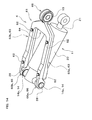
- FIG. 1 is a perspective view showing an aircraft reaction link 1 (hereinafter, may also be simply referred to as a "reaction link 1") according to Embodiment 1 of the present invention, together with a hydraulically driven cylinder 11.
- reaction link 1 an aircraft reaction link 1 (hereinafter, may also be simply referred to as a "reaction link 1") according to Embodiment 1 of the present invention, together with a hydraulically driven cylinder 11.
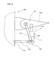
- FIG. 2 is a schematic diagram illustrating a state in which the reaction link 1 is attached to a body 100 of an aircraft, together with a part of the body 100.
- the reaction link 1 that is used as a constituent component of an actuator for driving a control surface 102 of the aircraft is attached to a body frame 101 of the body 100, and is provided so as to prevent a load applied to the control surface 102 from directly affecting the body frame 101.
- Examples of aircraft moving surfaces (flight control surfaces) constituting the control surface 102 include an aileron, a rudder, and an elevator.
- the reaction link 1 is coupled to the hydraulically driven cylinder 11.
- the cylinder 11 includes a cylinder body 20 and a rod portion 21.
- the cylinder 11 is actuated by supplying and discharging pressure oil to and from the inside of the cylinder body 20 using a hydraulic system (not shown) provided in an aircraft (not shown), and the cylinder 11 is actuated such that it is displaced so as to extend or contract from or into the cylinder body 20.
- the cylinder 11 is attached pivotably to the control surface 102 via a hinge portion or the like.
- the cylinder 11 is supported relative to the body frame 101 via a supporting member 103.
- the cylinder 11 is coupled pivotably to the supporting member 103 (in FIG. 1 , the illustration of a state of coupling between the cylinder 11 and the supporting member 103 has been omitted).
- the tip end of the rod portion 21 need not be directly attached to the control surface, and may be attached pivotably to the horn arm member attached to the control surface.
- the reaction link 1 includes a reaction link body 12, a bearing 13, bushes 14, fastening members 15, and so forth.
- FIG. 3 is a perspective view of the reaction link 1.
- FIG. 4 is a plan view of the reaction link 1.
- the reaction link body 12 of the reaction link 1 shown in FIGS. 1 to 4 is provided as a link element formed in the shape of a portal, and includes a pair of linear portions 22 (22a, 22b), a coupling portion 23, a fulcrum shaft attachment portion 24, and cylinder attachment portions 25.
- the reaction link body 12 includes, as will be described later, a metal frame 29 and a composite frame 30, and the metal frame 29 and the composite frame 30 are bonded together into one unit, thus forming the pair of linear portions 22 and the coupling portion 23 described above.
- the pair of linear portions 22 of the reaction link body 12 are made up of a linear portion 22a and a linear portion 22b disposed substantially parallel to each other and each extending linearly.
- the coupling portion 23 is formed as a portion extending so as to connect to one end of each of the pair of linear portions 22 on the same side via bent portions (26a, 26b) and to couple those ends to each other.
- the coupling portion 23 is formed so as to extend in a direction substantially orthogonal to the linear portion 22a and the linear portion 22b, and the bent portions (26a, 26b) are formed as portions that are bent at substantially a right angle.
- the coupling portion 23 is formed so as to connect to one end of the linear portion 22a via the bent portion 26a, to connect to one end of the linear portion 22b via the bent portion 26b, and to couple those ends of the pair of linear portions 22a and 22b to each other.
- the fulcrum shaft attachment portion 24 of the reaction link body 12 is provided so as to protrude from the center portion of the coupling portion 23 (the center portion in the direction in which the pair of linear portions 22 are coupled) toward the control surface 102. Also, the fulcrum shaft attachment portion 24 is provided as a portion that can be attached pivotably via the bearing 13 to a fulcrum shaft 27 (see FIG. 2 ) for rotatably supporting the control surface 102 with respect to the body frame 101. Further, the fulcrum shaft attachment portion 24 is formed as a cylindrical portion integrated with the coupling portion 23 and having a shorter axial length, and the outer ring of the bearing 13 described above is fixed by fitting to the inner wall of the fulcrum shaft attachment portion 24.
- the reaction link body 12 is coupled pivotably to the control surface 102 at the fulcrum shaft attachment portion 24.
- the cylinder attachment portions 25 of the reaction link body 12 are provided as the other end of each of the pair of linear portions 22 that is opposite from the coupling portion 23.
- the cylinder attachment portions 25 are made up of a cylinder attachment portion 25a provided as the other end of the linear portion 22a and a cylinder attachment portion 25b provided as the other end of the linear portion 22b.
- a through hole is formed in each of the cylinder attachment portions (25a, 25b), and the bushes 14 are attached by fitting to the through holes.
- the bushes 14 are made up of a bush 14a for being fixed to the cylinder attachment portion 25a and a bush 14b for being fixed to the cylinder attachment portion 25b.
- the bushes 14a and 14b are each formed in a cylindrical shape having a through hole through which a pivot shaft 28, which will be described later, penetrates.
- the bushes (14a, 14b) are each configured as a slidable member whose inner perimeter comes into slidable contact with the outer perimeter of the pivot shaft 28. Consequently, the cylinder attachment portions (25a, 25b) are attached pivotably to the pivot shafts 28. As shown in FIG.
- the pivot shafts 28 described above are provided as a pair of cylindrical portions that are formed integrally with the cylinder body 20 at the other end of the cylinder body 20 of the cylinder 11 (the side opposite from the side where the rod portion 21 protrudes). Also, the pivot shafts 28 are formed so as to protrude in the opposite directions from each other along the same straight line on both lateral sides of the other end of the cylinder body 20. The pivot shafts 28 come into slidable contact with the bushes 14 and are held in a rotatable state. Consequently, the cylinder attachment portions (25a, 25b) of the reaction link body 12 are attached pivotably to the other end of the cylinder 11 via the bushes 14 and the pivot shafts 28.
- the reaction link body 12 is coupled pivotably to the cylinder 11 and the control surface 102.
- the pivot shafts 28 are formed integrally with the cylinder body 20
- pivot shafts 28 that are each formed as a separate part may be fixed to the cylinder body 20, or the other end of the cylinder body 20 may be attached rotatably to pivot shafts 28 that are each provided as a separate part.
- this embodiment has been described taking, as an example, the bushes 14 as elements for rotatably holding the pivot shafts 28 relative to the cylinder attachment portions 25, this need not be the case.
- bearings may be provided as elements for rotatably holding the pivot shafts 28 relative to the cylinder attachment portions 25.
- FIG. 5 is a cross-sectional view looking in the direction of arrows A-A in FIG. 4 .
- the reaction link body 12 is configured by bonding the metal frame 29 and the composite frame 30 together, thus forming the pair of linear portions 22 and the coupling portion 23.
- the metal frame 29 is made of a metallic material (e.g., titanium alloy), is provided so as to extend across the coupling portion 23 and the pair of linear portions 22, and includes a body member 31 and end members (32, 33).
- the body member 31 is provided as a member constituting, together with a composite frame 30, which will be described later, the basic skeleton of the pair of linear portions 22 and the coupling portion 23, extending across the pair of linear portions 22 and the coupling portion 23, and also constituting the fulcrum shaft attachment portion 24.
- a pair of plate-like portions (31a, 31a) and a bridging portion 31b are provided in portions of the body member 31 that are provided in the pair of linear portions 22.
- the pair of plate-like portions (31a, 31a) are each formed as a plate-like portion and are provided as a pair of portions that are arranged parallel to each other.
- the bridging portion 31b is provided as a portion that is connected, substantially perpendicularly, to one edge of each of the pair of plate-like portions (31a, 31a) and that bridges the pair of plate-like portions (31a, 31a) by coupling them.
- the pair of plate-like portions (31a, 31a) and the bridging portion 31b that are disposed so as to extend in each of the linear portions (22a, 22b) are disposed alongside each other in the thickness direction of the reaction link 1 (the direction indicated by double-ended arrow D in FIG. 5 ).
- the cross section of the body member 31 that is perpendicular to the pair of plate-like portions (31a, 31a) and the bridging portion 31b is formed in a cross-sectional shape such as that of a square pipe one side of which is absent and thus is open toward the outside in the width direction of the reaction link 1. Forming such a cross sectional shape enables a configuration that is light-weight and that can secure a large geometrical moment of inertia.
- the thickness direction of the reaction link 1 is defined as a direction that is perpendicular to both the width direction of the reaction link 1 (the direction indicated by double-ended arrow B in FIG.
- the width direction of the reaction link 1 is defined as a direction in which the pair of linear portions 22 (22a, 22b) is disposed alongside each other.
- the portion of the body member 31 that constitutes the coupling portion 23 and the fulcrum shaft attachment portion 24 is formed integrally with the pair of plate-like portions (31a, 31a) and the bridging portion 31b described above. Also, the fulcrum shaft attachment portion 24 is disposed such that its axial direction (the direction of the cylinder axis) is parallel to the width direction of the reaction link 1.
- the end members (32, 33) are each formed as a member constituting a part of the surface portion of the other end of each of the cylinder attachment portions 25 and the linear portions (22a, 22b).
- the end member 32 is provided with the cylinder attachment portion 25a and a pair of protruding portions formed in the shape of plates extending parallel to each other and protruding from the cylinder attachment portion 25a in the longitudinal direction of the linear portion 22a.
- the end member 33 is provided with the cylinder attachment portion 25b and a pair of protruding portions formed in the shape of plates extending parallel to each other and protruding from the cylinder attachment portion 25b in the longitudinal direction of the linear portion 22b.
- the pairs of protruding portions of each of the end members (32, 33) constitute the surface portion on both sides in the thickness direction at the other end of each of the linear portions (22a, 22b).
- the metal frame 29 includes the body member 31 and the end members (32, 33), and the body member 31 and the end members (32, 33) are bonded together by fastening members 15b, which will be described later, such that they are integrated into one unit. Consequently, the metal frame 29 is provided so as to extend from the fulcrum shaft attachment portion 24 via the coupling portion 23 and the pair of linear portions 22 to the cylinder attachment portions 25.
- the composite frame 30 shown in FIGS. 3 to 5 is provided so as to extend across the pair of linear portions 22 and the coupling portion 23.
- the composite frame 30 is disposed inside the body member 31 of the metal frame 29 in the pair of linear portions 22 and the coupling portion 23. Consequently, the metal frame 29 and the composite frame 30 are disposed overlapping in the width direction of the reaction link 1. Also, the composite frame 30 is bonded by fastening members 15a, which will be described later, to the metal frame 29 provided in the pair of linear portions 22 on lateral surfaces on the insides in the width direction. Further, the composite frame 30 is made of carbon fiber-reinforced plastic (CFRP). Note that the composite frame 30 may be made of fiber-reinforced plastic other than carbon fiber-reinforced plastic.
- CFRP carbon fiber-reinforced plastic
- the composite frame 30 may be made of fiber-reinforced plastic such as glass fiber-reinforced plastic, glass mat reinforced plastics, boron fiber-reinforced plastic, aramid fiber-reinforced plastic, polyethylene fiber-reinforced plastic, and Zylon fiber-reinforced plastic.
- a pair of plate-like portions (30a, 30a) and a bridging portion 30b are provided in portions of the composite frame 30 that are provided in the pair of linear portions 22.
- the pair of plate-like portions (30a, 30a) are each formed as a plate-like portion and are provided as a pair of portions that are arranged parallel to each other.
- the bridging portion 30b is provided as a portion that is connected, substantially perpendicularly, to one edge of each of the pair of plate-like portions (30a, 30a) and that bridges the pair of plate-like portions (30a, 30a) by coupling them.
- the pair of plate-like portions (30a, 30a) and the bridging portion 30b that are disposed so as to extend in each of the linear portions (22a, 22b) are disposed alongside each other in the thickness direction of the reaction link 1.
- the cross section of the composite frame 30 that is perpendicular to the pair of plate-like portions (30a, 30a) and the bridging portion 30b is formed in a cross-sectional shape such as that of a square pipe one side of which is absent and thus is open toward the inside in the width direction of the reaction link 1. Forming such a cross sectional shape enables a configuration that is light-weight and that can secure a large geometrical moment of inertia.
- the fastening members 15 are each provided as a member that bonds the metal frame 29 and the composite frame 30 together into one unit as the reaction link body 12. Also, as shown in FIGS.
- fastening members 15a that bond the body member 31 and the composite frame 30 together, fastening members 15b that bond the body member 31 and the end members (32, 33) together, and fastening members 15c that bond the composite frame 30 and the end members (32, 33) together are provided as the fastening members 15.
- the fastening members 15a are each configured as a unit including a bolt and a nut that is screwed to the bolt, and a plurality of such units (in this embodiment, four units) are provided.
- each of the fastening members 15a the bolt penetrates through the bridging portion 31b of the body member 31 of the metal frame 29 and the bridging portion 30b of the composite frame 30 in the width direction of the reaction link 1, and the nut is screwed to that bolt. Consequently, the body member 31 and the composite frame 30 are bonded together in a state in which the bridging portion 31b and the bridging portion 30b are in close contact.
- each of the fastening members 15a is disposed at both longitudinal ends of the linear portions (22a, 22b).
- the fastening members 15b are each configured as a unit including a bolt, a nut that is screwed to the bolt, and a straight bush.
- a plurality of such units (in this embodiment, four units) are provided, and the same number of the units (two units for each) are disposed for the linear portion 22a and the linear portion 22b.
- the bolt penetrates through the pair of protruding portions of the end members (32, 33) of the metal frame 29 and the pair of plate-like portions (31a, 31a) of the body member 31 of the metal frame 29 in the thickness direction of the reaction link 1, and the nut is screwed to that bolt. Consequently, the body member 31 and the end member 32 are bonded together, and likewise, the body member 31 and the end member 33 are bonded together.
- the fastening members 15c are each configured as a unit including a bolt, a nut that is screwed to the bolt, and a straight bush.
- a plurality of such units in this embodiment, four units are provided, and the same number of the units (two units for each) are disposed for the linear portion 22a and the linear portion 22b.
- the bolt penetrates through the pair of protruding portions of the end members (32, 33) of the metal frame 29 and the pair of plate-like portions (30a, 30a) of the composite frame 30 in the thickness direction of the reaction link 1, and the nut is screwed to the bolt.
- the straight bush in each of the fastening members 15b and the fastening members 15c is formed as a cylindrical member.
- the bolt of each of the fastening members (15b, 15c) is disposed so as to penetrate through the straight bush.
- the straight bush of each of the fastening members 15b is disposed between the pair of plate-like portions (31a, 31a), with both of their ends in the direction of the cylinder axis in contact with the corresponding plate-like portion 31a of the pair of plate-like portions (31a, 31a).
- the straight bush in each of the fastening members 15c is disposed between the pair of plate-like portions (30a, 30a), with both of their ends in the direction of the cylinder axis in contact with the corresponding plate-like portion 30a of the pair of plate-like portions (30a, 30a).
- the straight bush being provided in this way, the pair of plate-like portions (31a, 31a) and the pair of plate-like portions (30a, 30a) are prevented from deformation that could be caused by fastening power exerted when the bolt and the nut are screwed together in each of the fastening members (15b, 15c).
- a hydraulic system is actuated in accordance with an instruction from a controller (not shown), and pressure oil is supplied and discharged to and from the cylinder body 20 of the cylinder 11.
- a controller not shown
- pressure oil is supplied and discharged to and from the cylinder body 20 of the cylinder 11.
- the rod portion 21 is displaced such that it extends or contracts from or into the cylinder body 20. Consequently, the control surface 102 is driven at one end of the rod portion 21 of the cylinder 11 that is pivotable about the pivot shafts 28.
- reaction link body 12 is attached pivotably to the fulcrum shaft 27 of the control surface 102 and the other end thereof is attached pivotably to the pivot shafts 28 as described above, and therefore the control surface 102 is driven so as to pivot about the fulcrum shaft 27.
- the reaction link 1 is configured by bonding the metal frame 29 and the composite frame 30 together, as described above. Therefore, provision of the metal frame 29 allows the reaction link 1 to achieve a greater improvement in fire resistance of an aircraft, for example, at the time of occurrence of a lightning strike during flight, as compared to an aircraft reaction link composed only of fiber-reinforced plastic.
- the pair of linear portions 22 and the coupling portion 23 of the reaction link body 12 are formed by bonding the metal frame 29 and the composite frame 30 together.
- the composite frame 30 is made of fiber-reinforced plastic, which has a significantly smaller specific gravity (i.e., also has a significantly smaller density) and has a significantly greater specific strength than light metal such as titanium alloy. Accordingly, it is possible to achieve weight reduction as compared to conventional aircraft reaction links made of metal such as titanium alloy, and to secure strength and rigidity that are equal to or greater than those achieved with conventional reaction links.
- the metal frame 29 is provided so as to extend from the fulcrum shaft attachment portion 24 via the coupling portion 23 and the pair of linear portions 22 to the cylinder attachment portions 25, and therefore a sufficient rigidity against a multi-directional load exerted on the aircraft reaction link 1 formed in the shape of a portal can also be secured. Accordingly, with this embodiment, it is possible to provide an aircraft reaction link 1 that can secure strength and rigidity that are equal to or greater than those achieved with conventional aircraft reaction links, while achieving weight reduction, and also to secure a sufficient rigidity against a multi-directional load.
- the composite frame 30 is bonded to the metal frame 29 on inner lateral faces of the metal frame 29 in the width direction, and thereby, the metal frame 29 and the composite frame 30 are integrated into one unit in a state in which they overlap each other in the width direction. Accordingly, it is possible to efficiently disperse and support the load in the longitudinal direction in the metal frame 29 and the composite frame 30 that extend along the pair of linear portions 22, while also suppressing the occurrence of an unbalanced load in the width direction. This makes it possible to efficiently secure a greater rigidity as the aircraft reaction link 1 as a whole.
- reaction link 2 (hereinafter, may also be simply referred to as a "reaction link 2") according to Embodiment 2 of the present invention will be described.
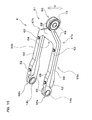
- FIG. 6 is a perspective view showing the reaction link 2 together with a cylinder 11.
- the reaction link 2 is used as a constituent component of an actuator for driving a control surface 102 of an aircraft, and is attached to a body frame 101 of a body 100 (see FIG. 2 ).
- the reaction link 2 is coupled pivotably to the control surface 102 and the cylinder 11, and includes a reaction link body 34, a bearing 13, bushes 14, fastening members 35 and so forth.
- the reaction link 2 is different from the reaction link 1 of Embodiment 1 in the configuration of the reaction link body 34.
- the differences in configuration from Embodiment 1 will be described. The description of those elements configured in the same manner as in Embodiment 1 has been omitted by using the same reference numerals in the drawings, or by referring to the same reference numerals.
- FIG. 7 is a perspective view of the reaction link 2.
- FIG. 8 is a plan view of the reaction link 2.
- the reaction link body 34 of the reaction link 2 shown in FIGS. 6 to 8 is provided as a link element formed in the shape of a portal, and includes a pair of linear portions 36 (36a, 36b), a coupling portion 37, a fulcrum shaft attachment portion 38, and cylinder attachment portions 39.
- the reaction link body 34 includes a metal frame 41 and a composite frame 42, and is configured by bonding the metal frame 41 and the composite frame 42 together into one unit, thus forming the pair of linear portions 36, the coupling portion 37, the fulcrum shaft attachment portion 38, and the cylinder attachment portions 39 described above.
- the pair of linear portions 36 of the reaction link body 34 are made up of a linear portion 36a and a linear portion 36b that are disposed substantially parallel to each other and each extend linearly.
- the coupling portion 37 is formed as a portion connecting to one end of each of the pair of linear portions 36 on the same side via bent portions (40a, 40b), and extending so as to couple those ends to each other. That is, the coupling portion 37 is formed so as to connect to one end of the linear portion 36a via the bent portion 40a, connect to one end of the linear portion 36b via the bent portion 40b, and couple those ends of the linear portion 36a and the linear portion 36b to each other.
- the fulcrum shaft attachment portion 38 of the reaction link body 34 is provided so as to protrude from the center portion of the coupling portion 37 toward the control surface 102. Also, the fulcrum shaft attachment portion 38 is provided as a portion that can be attached pivotably to a fulcrum shaft 27 (see FIG. 2 ) via the bearing 13. Further, the fulcrum shaft attachment portion 38 is formed as a portion integrated with the coupling portion 37 and having a second through hole 44 formed inside thereof, and the outer ring of the bearing 13 is fixed by fitting to the inner wall of the second through hole 44. Consequently, the reaction link body 34 is coupled pivotably to the control surface 102 at the fulcrum shaft attachment portion 38.
- the cylinder attachment portions 39 of the reaction link body 34 are provided as the other end of each of the pair of linear portions 36 that is opposite from the coupling portion 37. Also, the cylinder attachment portions 39 are made up of a cylinder attachment portion 39a that is the other end of the linear portion 36a and a cylinder attachment portion 39b that is the other end of the linear portion 36b. As with Embodiment 1, a bush 14a is attached to the cylinder attachment portion 39a and a bush 14b is attached to the cylinder attachment portion 39b. Consequently, each of the cylinder attachment portions (39a, 39b) is attached pivotably to the pivot shaft 28. As shown in FIGS.
- the reaction link body 34 is configured by bonding the metal frame 41 and the composite frame 42 together, thus forming the pair of linear portions 36, the coupling portion 37, the fulcrum shaft attachment portion 38, and the cylinder attachment portions 39.
- the metal frame 41 is made of a metallic material (e.g., titanium alloy), and is provided so as to extend from the cylinder attachment portions 39 via the pair of linear portions 36 and the coupling portion 37 to the fulcrum shaft attachment portion 38.
- the portion of the metal frame 41 that is provided in the pair of linear portions 36 and the coupling portion 37 is formed as a portion having a rectangular cross section and extending in a plate-like form.
- a pair of plate-like portions extending substantially parallel to each other and having a second through hole 44, which will be described later, and a portion bridging the pair of plate-like portions so as to couple the pair of plate-like portions into one unit at their tip ends is formed in the portion of the metal frame 41 that is provided in the fulcrum shaft attachment portion 38.
- the composite frame 42 is made of carbon fiber-reinforced plastic as with the composite frame 30 of Embodiment 1. Note that the composite frame 42 may be made of fiber-reinforced plastic other than carbon fiber-reinforced plastic.
- the composite frame 42 is provided so as to extend from the cylinder attachment portions 39 via the pair of linear portions 36 and the coupling portion 37 to the fulcrum shaft attachment portion 38, and is disposed inside the metal frame 41. Consequently, the metal frame 41 and the composite frame 42 are disposed overlapping in the width direction of the reaction link 2 (the direction indicated by double-ended arrow B in FIG. 8 ). Also, the composite frame 42 is bonded by the fastening members 35 to the metal frame 41 provided in the pair of linear portions 36 on inner lateral faces of the metal frame 41 in the width direction.
- the fastening members 35 are each provided as a member that bonds the metal frame 41 and the composite frame 42 together such that they are integrated as the reaction link body 34.
- the fastening members 35 are each configured as a unit including a bolt and a nut that is screwed to the bolt, and a plurality of such units (in this embodiment, four units) are provided. Also, in each of the fastening members 35, the bolt penetrates through the metal frame 41 and the composite frame 42 in the pair of linear portions 36 in the width direction of the reaction link 2, and the nut is screwed to that bolt. Consequently, the metal frame 41 and the composite frame 42 are bonded together in close contact. Note that each of the fastening members 35 is disposed at both longitudinal ends of each of the linear portions (36a, 36b).
- a first through hole 43 that is shaped so as to pass through and communicate with the metal frame 41 and the composite frame 42 is formed in each of the cylinder attachment portions (39a, 39b) (see FIG. 8 ). Also, in the first through holes 43, the bushes (14a, 14b) each serving as a cylindrical slidable member that comes into slidable contact with the outer perimeter of the pivot shaft 28 are fixed from the metal frame 41 to the composite frame 42. Further, in the reaction link body 34, the portion of the composite frame 42 that constitutes the fulcrum shaft attachment portion 38 is disposed in a fitted state between the above-described pair of plate-like portions of the metal frame 41 that constitutes the fulcrum shaft attachment portion 38.
- a second through hole 44 that is shaped so as to pass through and communicate with the metal frame 41 and the composite frame 42 is formed in the fulcrum shaft attachment portion 38 (see FIG. 8 ). Also, in the second through hole 44, the bearing 13 for rotatably holding the fulcrum shaft 27 is fixed across the metal frame 41 to the composite frame 42.
- the reaction link 2 described above is actuated in the same manner as the reaction link 1 of Embodiment 1.
- the reaction link 2 is actuated along with the cylinder 11, and thereby the control surface 102 is driven so as to pivot about the fulcrum shaft 27.
- the pair of linear portions 36 and the coupling portion 37 of the reaction link body 34 are formed by bonding the metal frame 41 and the composite frame 42 together.
- the composite frame 42 is made of fiber-reinforced plastic, which has a significantly smaller specific gravity and a significantly greater specific strength than light metal such as titanium alloy. Accordingly, it is possible to achieve weight reduction as compared to conventional aircraft reaction links made of metal such as titanium alloy, and to secure strength and rigidity that are equal to or greater than those achieved with conventional reaction links.
- the metal frame 41 is provided so as to extend from the fulcrum shaft attachment portion 38 via the coupling portion 37 and the pair of linear portions 36 to the cylinder attachment portions 39, and therefore a sufficient rigidity against a multi-directional load exerted on the aircraft reaction link 2 formed in the shape of a portal can also be secured. Accordingly, with this embodiment, it is possible to provide an aircraft reaction link 2 that can secure strength and rigidity that are equal to or greater than those achieved with conventional aircraft reaction links, while achieving weight reduction, and also to secure a sufficient rigidity against a multi-directional load.
- the composite frame 42 is bonded to the metal frame 41 on inner lateral faces of the metal frame 41 in the width direction, and thereby, the metal frame 41 and the composite frame 42 are integrated into one unit in a state in which they overlap each other in the width direction. Accordingly, it is possible to efficiently disperse and support the load in the longitudinal direction in the metal frame 41 and the composite frame 42 that extend along the pair of linear portions 36, while also suppressing the occurrence of an unbalanced load in the width direction. This makes it possible to efficiently secure a greater rigidity as the aircraft reaction link 2 as a whole. Further, with the aircraft reaction link 2, the composite frame 42 is provided from the pair of linear portions 36 to the cylinder attachment portions 39, and therefore it is possible to achieve a further weight reduction.
- the first through holes 43 passing through both the metal frame 41 and the composite frame 42 are provided in the cylinder attachment portions 39, and the bushes 14 for rotatably holding the pivot shafts 28 are fixed to both the metal frame 41 and the composite frame 42 in the first through holes 43. Accordingly, it is possible to realize a structure in which the aircraft reaction link 2 for which weight reduction has been achieved even for the cylinder attachment portions 39 can be supported relative to the pivot shafts 28 more stably. Further, with the aircraft reaction link 2, the composite frame 42 is provided from the pair of linear portions 36 to the fulcrum shaft attachment portion 38, and therefore it is possible to achieve a further weight reduction.
- the second through hole 44 passing through both the metal frame 41 and the composite frame 42 is formed in the fulcrum shaft attachment portion 38, and the bearing 13 for rotatably supporting the fulcrum shaft 27 is fixed to both the metal frame 41 and the composite frame 42 in the second through hole 44. Accordingly, it is possible to realize a structure in which the aircraft reaction link 2 for which weight reduction has been achieved even for the fulcrum shaft attachment portion 38 can be supported relative to the fulcrum shaft 27 more stably.
- reaction link 3 (hereinafter, may also be simply referred to as a "reaction link 3") according to Embodiment 3 of the present invention will be described.
- FIG. 9 is a perspective view showing the reaction link 3 together with a cylinder 11.
- the reaction link 3 is used as a constituent component of an actuator for driving a control surface 102 of an aircraft, and is attached to a body frame 101 of a body 100 (see FIG. 2 ).
- the reaction link 3 is coupled pivotably to the control surface 102 and the cylinder 11, and includes a reaction link body 45, a bearing 13, bushes 14, fastening members 46 and so forth.
- the reaction link 3 is different from the reaction link 1 of Embodiment 1 in the configuration of the reaction link body 45.
- the differences in configuration from Embodiment 1 will be described. The description of those elements configured in the same manner as in Embodiment 1 has been omitted by using the same reference numerals in the drawings, or by referring to the same reference numerals.
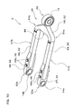
- FIG. 10 is a perspective view of the reaction link 3
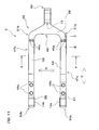
- FIG. 11 is a plan view of the reaction link 3.
- FIG. 12 is a cross-sectional view looking in the direction of arrow E-E in FIG. 11
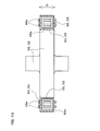
- FIG. 13 is a cross-sectional view looking in the direction of arrow F-F in FIG. 11
- the reaction link body 45 of the reaction link 3 shown in FIGS. 9 to 13 is provided as a link element formed in the shape of a portal, and includes a pair of linear portions 47 (47a, 47b), a coupling portion 48, a fulcrum shaft attachment portion 49, and cylinder attachment portions 50.
- the reaction link body 45 includes, as will be described later, a metal frame 52 and a composite frame 53, and the metal frame 52 and the composite frame 53 are bonded together into one unit, thus forming the pair of linear portions 47 and the coupling portion 48 described above.
- the pair of linear portions 47 of the reaction link body 45 are made up of a linear portion 47a and a linear portion 47b that are disposed substantially parallel to each other and each extend linearly.
- the coupling portion 48 is formed as a portion connecting to one end of each of the pair of linear portions 47 on the same side via bent portions (51a, 51b), and extending so as to couple those ends to each other. That is, the coupling portion 48 is formed so as to connect to one end of the linear portion 47a via the bent portion 51a, connect to one end of the linear portion 47b via the bent portion 51b, and couple those ends of the linear portion 47a and the linear portion 47b to each other.
- the fulcrum shaft attachment portion 49 of the reaction link body 45 is provided so as to protrude from the center portion of the coupling portion 48 toward the control surface 102. Also, the fulcrum shaft attachment portion 49 is provided as a portion that can be attached pivotably to a fulcrum shaft 27 (see FIG. 2 ) via the bearing 13. Furthermore, the fulcrum shaft attachment portion 49 is formed as a cylindrical portion integrated with the coupling portion 48 and having a shorter axial length, and the outer ring of the bearing 13 is fixed by fitting to the inner wall of the fulcrum shaft attachment portion 49. Consequently, the reaction link body 45 is coupled pivotably to the control surface 102 at the fulcrum shaft attachment portion 49.
- the cylinder attachment portions 50 of the reaction link body 45 are provided as the other end of each of the pair of linear portions 47 that is opposite from the coupling portion 48. Also, the cylinder attachment portions 50 are made up of a cylinder attachment portion 50a that is the other end of the linear portion 47a and a cylinder attachment portion 50b that is the other end of the linear portion 47b. As with Embodiment 1, a bush 14a is attached to the cylinder attachment portion 50a, and a bush 14b is attached to the cylinder attachment portion 50b. Consequently, each of the cylinder attachment portions (50a, 50b) is attached pivotably to the pivot shaft 28.
- the reaction link body 45 is configured by bonding the metal frame 52 and the composite frame 53 together, thus forming the pair of linear portions 47.
- the metal frame 52 is made of a metallic material (e.g., titanium alloy), is provided so as to extend from the fulcrum shaft attachment portion 49 via the coupling portion 48 and the pair of linear portions 47 to the cylinder attachment portions 50, and includes pipe members (54, 55), a coupling member 56, and end members (57, 58).
- the pipe members (54, 55) each constitute a metal pipe portion of this embodiment that is provided in the pair of linear portions 47 and are each formed in the shape of a pipe having a hollow cross section.
- the pipe member 54 is provided so as to extend in the linear portion 47a, and the pipe member 55 is provided so as to extend in the linear portion 47b.
- the pipe members (54, 55) are each provided as a square pipe-like member.
- the coupling member 56 is provided as a member constituting the coupling portion 48 and the fulcrum shaft attachment portion 49, and the pipe members (54, 55) and the composite frame 53 are bonded together by fastening members 46a, which will be described later.
- the end members (57, 58) are each formed as a member constituting a part of the surface portion of the other end of each of the cylinder attachment portions 50 and the linear portions (47a, 47b).
- the end member 57 is provided with the cylinder attachment portion 50a and a pair of protruding portions formed in the shape of plates extending parallel to each other and protruding from the cylinder attachment portion 50a in the longitudinal direction of the linear portion 47a.
- the end member 58 is provided with the cylinder attachment portion 50b and a pair of protruding portions formed in the shape of plates extending parallel to each other and protruding from the cylinder attachment portion 50b in the longitudinal direction of the linear portion 47b.
- the pairs of protruding portions of each of the end members (57, 58) constitute the surface portion on both sides in the thickness direction at the other end of each of the linear portions (47a, 47b).
- the end members (57, 58) are bonded to the pipe members (54, 55) and the composite frame 53 via fastening members 46b, which will be described later.
- the composite frame 53 shown in FIGS. 12 and 13 is made of carbon fiber-reinforced plastic as with the composite frame 30 of Embodiment 1. Note that the composite frame 53 may be made of fiber-reinforced plastic other than carbon fiber-reinforced plastic.
- the composite frame 53 includes pipe members (59, 60).
- the pipe members (59, 60) each constitute a composite pipe portion of this embodiment that is provided in the pair of linear portions 47 and are each formed in the shape of a pipe having a hollow cross section.
- the pipe member 59 is provided so as to extend in the linear portion 47a, and the pipe member 60 is provided so as to extend in the linear portion 47b.
- the pipe members (59, 60) are each provided as a square pipe-like member.
- the pipe member 59 is disposed inside the pipe member 54 of the metal frame 52, and the pipe member 60 is disposed inside the pipe member 55 of the metal frame 52.
- the pipe member 54 and the pipe member 59 are bonded together as a double tube in which the inner wall of the pipe member 54 and the outer wall of the pipe member 59 are in close contact.
- the pipe member 55 and the pipe member 60 are bonded together as a double tube in which the inner wall of the pipe member 55 and the outer wall of the pipe member 60 are in close contact.
- the fastening members 46 are each provided as a member that bonds the metal frame 52 and the composite frame 53 together into one unit as the reaction link body 45.
- Fastening members 46a and fastening members 46b are provided as the fastening members 46.
- the fastening members 46a are each provided as a member that bonds the pipe members (54, 55) of the metal frame 52 and the coupling member 56 to the pipe members (59, 60) of the composite frame 53.
- the fastening members 46b are each provided as a member that bonds the pipe members (54, 55) and the end members (57, 58) of the metal frame 52 to the pipe members (59, 60) of the composite frame 53.
- the fastening members 46a are each configured as a unit including a bolt and a nut that is screwed to the bolt, and a plurality of such units (in this embodiment, four units) are provided. Also, in each of the fastening members 46a, the bolt penetrates through an end of each of the pipe members (54, 55), an end of each of the pipe members (59, 60), and an end of the coupling member 56 in the thickness direction of the reaction link 3 (the direction indicated by double-ended arrow D in FIG. 13 ), and the nut is screwed to the bolt. As shown in FIGS. 12 and 13 , joint portions 56a extending in the shape of a short square pipe are provided at ends of the coupling member 56.
- the pipe members (54, 55), the pipe members (59, 60), and the coupling member 56 are bonded together in a state in which each of the pipe members (59, 60) is fitted inside each of the pipe members (54, 55) and each of the joint portions 56a is fitted inside each of the pipe members (59, 60).
- two fastening members 46a are disposed alongside each other in the width direction of the reaction link 3 (the direction indicated by double-ended arrow B in FIG. 11 ) in each of the bonded portions between the coupling portion 48 and the linear portions (47a, 47b).
- the metal frames 52 are provided on both the side of the pair of linear portions 47 and the coupling portion 48 side. Accordingly, even if a tensile load is exerted between the coupling portion 48 and the pair of linear portions 47 in the longitudinal direction of the pair of linear portions 47 (the direction indicated by double-ended arrow C in FIGS. 11 and 12 ), it is possible to prevent the tensile load from being concentrated at ends of the composite frame 53. This makes it possible to prevent the composite frame 53 from being damaged by a tensile load exerted in the longitudinal direction of the pair of linear portions 47.
- the fastening members 46b are each configured as a unit including a bolt and a nut that is screwed to the bolt, and a plurality of such units (in this embodiment, four units) are provided. Also, in each of the fastening members 46b, the bolt penetrates through the pair of protruding potions of the end members (57, 58), an end of each of the pipe members (54, 55), and an end of each of the pipe members (59, 60) in the thickness direction of the reaction link 3, and the nut is screwed to the bolt.
- end members (57, 58), the pipe members (54, 55), and the pipe members (59, 60) are bonded together in a state in which each of the pipe members (54, 55) is fitted between the pair of protruding portions of each of the end members (57, 58), and each of the pipe members (59, 60) is fitted inside each of the pipe members (54, 55).
- two fastening members 46b are disposed alongside each other in the longitudinal direction of the pair of linear portions 47 in each of the bonded portions between the end members (57, 58) and the pipe members (54, 55, 59, 60).
- the metal frames 52 (54, 55, 57, 58) is provided for both bonded portions. Accordingly, even if a tensile load is exerted at the above-described bonded portions in the longitudinal direction of the pair of linear portions 47, it is possible to prevent the tensile load from being concentrated at ends of the composite frame 53. This makes it possible to prevent the composite frame 53 from being damaged by a tensile load exerted in the longitudinal direction of the pair of linear portions 47.
- the reaction link 3 described above is actuated in the same manner as the reaction link 1 of Embodiment 1.
- the reaction link 3 is actuated along with the cylinder 11, and thereby the control surface 102 is driven so as to pivot about the fulcrum shaft 27.
- the pair of linear portions 47 and the coupling portion 48 of the reaction link body 45 are formed by bonding the metal frame 52 and the composite frame 53 together.
- the composite frame 53 is made of fiber-reinforced plastic, which has a significantly smaller specific gravity and a significantly greater specific strength than light metal such as titanium alloy. Accordingly, it is possible to achieve weight reduction as compared to conventional aircraft reaction links made of metal such as titanium alloy, and to secure strength and rigidity that are equal to or greater than those achieved with conventional reaction links.
- the metal frame 52 is provided so as to extend from the fulcrum shaft attachment portion 49 via the coupling portion 48 and the pair of linear portions 47 to the cylinder attachment portions 50, and therefore a sufficient rigidity against a multi-directional load exerted on the aircraft reaction link 3 formed in the shape of a portal can also be secured. Accordingly, with this embodiment, it is possible to provide an aircraft reaction link 3 that can secure strength and rigidity that are equal to or greater than those achieved with conventional aircraft reaction links, while achieving weight reduction, and also to secure a sufficient rigidity against a multi-directional load.
- the metal frame 52 and the composite frame 53 include their respective pipe members (54, 55, 59, 60) that are pipe portions each having a hollow cross section, and these pipe portions are bonded together in close contact as a double tube, and integrated into one unit. Accordingly, it is possible to efficiently disperse and support the load in the longitudinal direction in the metal frame 52 and the composite frame 53 that extend along the pair of linear portions 47, while also suppressing the occurrence of an unbalanced load in a cross section perpendicular to the longitudinal direction. Since the metal frame 52 and the composite frame 53 are formed in the shape of a pipe in the pair of linear portions 47, it is possible to easily set the geometrical moment of inertia large, while realizing a configuration with a reduced weight.
- This embodiment is described, taking as an example, the aircraft reaction link 3 in which the pipe members (54, 55), which are the metal pipe portions, are disposed outside the pipe members (59, 60), which are the composite pipe portions.
- the metal pipe portions serve as electric conductors in case of a lightning strike during the flight of an aircraft, thus easily passing and releasing the lightning current to the aircraft body. This makes it possible to achieve anti-lightning performance that enables avoiding or suppressing the influence of a lightning strike.
- reaction link 4 (hereinafter, may also be simply referred to as a "reaction link 4") according to Embodiment 4 of the present invention will be described.
- FIG. 14 is a perspective view showing the reaction link 4 together with a cylinder 11.
- the reaction link 4 is used as a constituent component of an actuator for driving a control surface 102 of an aircraft, and is attached to a body frame 101 of a body 100 (see FIG. 2 ).
- the reaction link 4 is coupled pivotably to the control surface 102 and the cylinder 11, and includes a reaction link body 61, a bearing 13, bushes 14, fastening members 62 and so forth.
- the reaction link 4 is different from the reaction link 1 of Embodiment 1 in the configuration of the reaction link body 61.
- the differences in configuration from Embodiment 1 will be described. The description of those elements configured in the same manner as in Embodiment 1 has been omitted by using the same reference numerals in the drawings, or by referring to the same reference numerals.
- FIG. 15 is a perspective view of the reaction link 4.
- FIG. 16 is a plan view of the reaction link 4.
- the reaction link body 61 of the reaction link 4 shown in FIGS. 14 to 16 is provided as a link element formed in the shape of a portal, and includes a pair of linear portions 63 (63a, 63b), a coupling portion 64, a fulcrum shaft attachment portion 65, and cylinder attachment portions 66.
- the reaction link body 61 includes a metal frame 68 and a composite frame 69, and is configured by bonding the metal frame 68 and the composite frame 69 together into one unit, thus forming the pair of linear portions 63, the coupling portion 64, the fulcrum shaft attachment portion 65, and the cylinder attachment portions 66 described above.
- the pair of linear portions 63 of the reaction link body 61 are made up of a linear portion 63a and a linear portion 63b that are disposed substantially parallel to each other and each extend linearly.
- the coupling portion 64 is formed as a portion connecting to one end of each of the pair of linear portions 63 on the same side via bent portions (67a, 67b), and extending so as to couple those ends to each other.
- the coupling portion 64 is formed so as to connect to one end of the linear portion 63a via the bent portion 67a, connect to one end of the linear portion 63b via the bent portion 67b, and couple those ends of the linear portion 63a and the linear portion 63b to each other.
- the fulcrum shaft attachment portion 65 of the reaction link body 61 is provided so as to protrude from the center portion of the coupling portion 64 toward the control surface 102.
- the fulcrum shaft attachment portion 65 is provided as a portion that can be attached pivotably to a fulcrum shaft 27 (see FIG. 2 ) via the bearing 13.
- the fulcrum shaft attachment portion 65 is formed as a cylindrical portion integrated with the coupling portion 64 and having a shorter axial length, and the outer ring of the bearing 13 is fixed by fitting to the inner wall of the fulcrum shaft attachment portion 65.
- the reaction link body 61 is coupled pivotably to the control surface 102 at the fulcrum shaft attachment portion 65.
- the cylinder attachment portions 66 of the reaction link body 61 are provided as the other end of each of the pair of linear portions 63 that is opposite from the coupling portion 64.
- the cylinder attachment portions 66 are made up of a cylinder attachment portion 66a that is the other end of the linear portion 63a and a cylinder attachment portion 66b that is the other end of the linear portion 63b.
- a bush 14a is attached to the cylinder attachment portion 66a and a bush 14b is attached to the cylinder attachment portion 66b.
- each of the cylinder attachment portions (66a, 66b) is attached pivotably to the pivot shaft 28.
- the reaction link body 61 is configured by bonding the metal frame 68 and the composite frame 69 together, thus forming the pair of linear portions 63, the coupling portion 64, the fulcrum shaft attachment portion 65, and the cylinder attachment portions 66.
- the metal frame 68 is made of a metallic material (e.g., titanium alloy), and is provided so as to extend from the cylinder attachment portions 66 via the pair of linear portions 63 and the coupling portion 64 to the fulcrum shaft attachment portion 65.
- the portion of the metal frame 68 that is provided in the pair of linear portions 63 and the coupling portion 64 is formed as a portion extending in a plate-like form.
- a pair of ring-like portions disposed substantially parallel to each other and having a fourth through hole 71, which will be described later, provided therein are formed in the portion of the metal frame 68 that is provided in the fulcrum shaft attachment portion 65.
- the composite frame 69 is made of carbon fiber-reinforced plastic as with the composite frame 30 of Embodiment 1. Note that the composite frame 69 may be made of fiber-reinforced plastic other than carbon fiber-reinforced plastic.
- the composite frame 69 is provided so as to extend from the cylinder attachment portions 66 via the pair of linear portions 63 and the coupling portion 64 to the fulcrum shaft attachment portion 65. Also, the metal frame 68 and the composite frame 69 are disposed overlapping in the thickness direction of the reaction link 4 (the direction indicated by double-ended arrow D in FIG. 15 ) and bonded together by fastening members 62 in the major portion of the pair of linear portions 63 that includes the center portion (the portion excluding the other end of the pair of linear portions 63) in the longitudinal direction (the direction indicated by double-ended arrow C in FIG. 16 ).
- the fastening members 62 are each provided as a member that bonds the metal frame 68 and the composite frame 69 together such that they are integrated as the reaction link body 61. Also, the fastening members 62 are each configured as a unit including a bolt and a nut that is screwed to the bolt, and a plurality of such units (in this embodiment, four units) are provided. Also, in each of the fastening members 62, the bolt penetrates through the metal frame 68 and the composite frame 69 in the pair of linear portions 63 in the thickness direction of the reaction link 4, and the nut is screwed to that bolt. Consequently, the metal frame 68 and the composite frame 69 are bonded together in close contact in the thickness direction.
- each of the fastening members 62 is disposed at both longitudinal ends of each of the linear portions (63a, 63b).
- a third through hole 70 (see FIG. 16 ) that is shaped so as to pass through and communicate with an end of each of the metal frame 68 and the composite frame 69 (the portion constituting the cylinder attachment portions 66) that are disposed overlapping in the width direction of the reaction link 4 (the direction indicated by double-ended arrow B in FIG. 16 ) is provided in each of the cylinder attachment portions (66a, 66b).
- the bushes (14a, 14b) each serving as a cylindrical slidable member that comes into slidable contact with the outer perimeter of the pivot shaft 28 are fixed from the metal frame 68 to the composite frame 69.
- this embodiment illustrates a configuration in which an end of the metal frame 68 is disposed outside in the width direction and an end of the composite frame 69 is disposed inside in the width direction in the cylinder attachment portions (66a, 66b).
- the metal frame 68 and the composite frame 69 are configured to be bonded together in the major portion of the coupling portion 64 and the pair of linear portions 63 in a state in which they overlap in the thickness direction, and to be bonded together in the cylinder attachment portions 66 in a state in which they overlap in the width direction.
- the reaction link body 61 is provided with a portion that is formed such that a flat portion extends toward a skew position in each of the metal frame 68 and the composite frame 69 at the cylinder attachment portions (66a, 66b).
- the ring-like portion of the composite frame 69 that constitutes the fulcrum shaft attachment portion 65 is disposed in a fitted state between the above-described pair of ring-like portions of the metal frame 68 that constitutes the fulcrum shaft attachment portion 65. Furthermore, a fourth through hole 71 that is shaped so as to pass through and communicate with an end of each of the metal frame 68 and the composite frame 69 (the portion constituting the fulcrum shaft attachment portion 65) that are disposed overlapping in the width direction is formed in the fulcrum shaft attachment portion 65 (see FIG. 16 ).
- the bearing 13 for rotatably holding the fulcrum shaft 27 is fixed across the metal frame 68 to the composite frame 69.
- this embodiment illustrates a configuration in which an end of the metal frame 68 is disposed outside in the width direction and an end of the composite frame 69 is disposed inside in the width direction in the fulcrum shaft attachment portion 65.
- the metal frame 68 and the composite frame 69 are configured to be bonded together in the major portion of the coupling portion 64 and the pair of linear portions 63 in a state in which they overlap in the thickness direction, and to be bonded together in the fulcrum shaft attachment portion 65 in a state in which they overlap in the width direction.
- the reaction link body 61 is provided with a portion that is formed such that a flat portion extends toward a skew position in each of the metal frame 68 and the composite frame 69 at the fulcrum shaft attachment portion 65.
- the reaction link 4 described above is actuated in the same manner as the reaction link 1 of Embodiment 1. That is, the reaction link 4 is actuated along with the cylinder 11, and thereby the control surface 102 is driven so as to pivot about the fulcrum shaft 27.
- the pair of linear portions 63 and the coupling portion 64 of the reaction link body 61 are formed by bonding the metal frame 68 and the composite frame 69 together.
- the composite frame 69 is made of fiber-reinforced plastic, which has a significantly smaller specific gravity and a significantly greater specific strength than light metal such as titanium alloy. Accordingly, it is possible to achieve weight reduction as compared to conventional aircraft reaction links made of metal such as titanium alloy, and to secure strength and rigidity that are equal to or greater than those achieved with conventional reaction links. Furthermore, with the aircraft reaction link 4, the metal frame 68 is provided so as to extend from the fulcrum shaft attachment portion 65 via the coupling portion 64 and the pair of linear portions 63 to the cylinder attachment portions 66, and therefore a sufficient rigidity against a multi-directional load exerted on the aircraft reaction link 4 formed in the shape of a portal can also be secured.
- an aircraft reaction link 4 that can secure strength and rigidity that are equal to or greater than those achieved with conventional aircraft reaction links, while achieving weight reduction, and also to secure a sufficient rigidity against a multi-directional load. Furthermore, with the aircraft reaction link 4, the metal frame 68 and the composite frame 69 are bonded together and integrated into one unit in a state in which they overlap each other in the thickness direction in the major portion of the pair of linear portions 63 that includes the center portion in the longitudinal direction. Accordingly, it is possible to efficiently disperse and support the load in the longitudinal direction in the metal frame 68 and the composite frame 69 that extend along the pair of linear portions 63, while also suppressing the occurrence of an unbalanced load in the thickness direction.
- the composite frame 69 is provided from the pair of linear portions 63 to the cylinder attachment portions 66, and therefore it is possible to achieve a further weight reduction.
- the third through holes 70 passing through both the metal frame 68 and the composite frame 69 are provided in the cylinder attachment portions 66, and the bushes 14 for rotatably holding the pivot shafts 28 are fixed to both the metal frame 68 and the composite frame 69 in the third through holes 70. Accordingly, it is possible to realize a structure in which the aircraft reaction link 4 for which weight reduction has been achieved even for the cylinder attachment portions 66 can be supported relative to the pivot shafts 28 more stably.
- the composite frame 69 is provided from the pair of linear portions 63 to the fulcrum shaft attachment portion 65, and therefore it is possible to achieve a further weight reduction.
- the fourth through hole 71 passing through both the metal frame 68 and the composite frame 69 is formed in the fulcrum shaft attachment portion 65, and the bearing 13 for rotatably supporting the fulcrum shaft 27 is fixed to both the metal frame 68 and the composite frame 69 in the fourth through hole 71.
Landscapes
- Engineering & Computer Science (AREA)
- Automation & Control Theory (AREA)
- Aviation & Aerospace Engineering (AREA)
- Transmission Devices (AREA)
- Shafts, Cranks, Connecting Bars, And Related Bearings (AREA)
Abstract
Description
- This application claims priority to Japanese Patent Application No.
2009-281372 2009-281372 - The present invention relates to an aircraft reaction link that is used as a constituent component of an actuator for driving a control surface of an aircraft, and that can be coupled pivotably to the control surface and a hydraulically driven cylinder attached to the control surface or to a horn arm member.
- An aircraft is provided with control surfaces that are formed as moving surfaces (flight control surfaces) and are configured as an aileron, a rudder, an elevator, and the like. As a constituent component of an actuator for driving such control surfaces, aircraft reaction links as disclosed in
JP 05-97095A JP 62-165007A JP 05-97095A JP 62-165007A - In view of the above-described situations, it is an object of the present invention to provide an aircraft reaction link that can secure strength and rigidity that are equivalent to or greater than those achieved by the conventional technology while achieving weight reduction, and can also secure a sufficient rigidity against a multi-directional load.
- In order to achieve the above-described object, an air craft reaction link according to a first feature of the present invention is a reaction link that is used as a constituent component of an actuator for driving a control surface of an aircraft, and that can be coupled to a hydraulically driven cylinder whose one end is attached pivotably to the control surface or to a horn arm member attached to the control surface, of linear portions and a composite frame that is made of fiber-reinforced plastic and that is provided so as to extend at least in the pair of linear portions are bonded together, whereby the pair of linear portions and the coupling portion are formed, and the metal frame is provided so as to extend from the fulcrum shaft attachment portion to the cylinder attachment portion. With this configuration, the aircraft reaction link is formed by bonding together the metal frame constituting the pair of linear portions and the coupling portion and the composite frame constituting at least the pair of linear portions. The composite frame is made of fiber-reinforced plastic, which has a significantly smaller specific gravity (i.e., also has a significantly smaller density) and has a significantly greater specific strength than light metal such as titanium alloy. Accordingly, it is possible to achieve weight reduction as compared to conventional aircraft reaction links made of metal such as titanium alloy, and to secure strength and rigidity that are equal to or greater than those achieved with conventional reaction links. Furthermore, with this configuration, the metal frame is provided so as to extend from the fulcrum shaft attachment portion via the coupling portion and the pair of linear portions to the cylinder attachment portion, and therefore a sufficient rigidity against a multi-directional load exerted on the aircraft reaction link formed in the shape of a portal can also be secured. Accordingly, with this configuration, it is possible to provide an aircraft reaction link that can secure strength and rigidity that are equal to or greater than those achieved with conventional configurations, while achieving weight reduction, and also can secure a sufficient rigidity against a multi-directional load. According to a second feature of the present invention, in the aircraft reaction link having the first feature, the metal frame and the composite frame are disposed overlapping in a width direction that is the direction in which the pair of linear portions are disposed alongside each other, and the composite frame is bonded to the metal frame provided in the pair of linear portions on inner lateral faces or outer lateral faces of the metal frame in the width direction. With this configuration, the composite frame is bonded to the metal frame on inner lateral faces or outer lateral faces of the metal frame in the width direction, and thereby, the metal frame and the composite frame are integrated into one unit in a state in which they overlap each other in the width direction. Accordingly, it is possible to efficiently disperse and support the load in the longitudinal direction in the metal frame and the composite frame that extend along the pair of linear portions, while also suppressing the occurrence of an unbalanced load in the width direction. This makes it possible to efficiently secure a greater rigidity as the aircraft reaction link as a whole. According to a third feature of the present invention, in the aircraft reaction link having the second feature, a first through hole that is shaped so as to pass through and communicate with the metal frame and the composite frame is formed in the cylinder attachment portion that is provided as the other end of each of the pair of linear portions, and a bearing for rotatably holding the pivot shaft or a cylindrical slidable member coming into slidable contact with an outer perimeter of the pivot shaft is fixed to the first through hole from the metal frame to the composite frame. With this configuration, the composite frame is provided from the pair of linear portions to the cylinder attachment portion, and therefore it is possible to achieve a further weight reduction. Also, the first through hole passing through both the metal frame and the composite frame is provided in the cylinder attachment portion, and the bearing or the slidable member for rotatably holding the pivot shaft is fixed to both the metal frame and the composite frame in the first through hole. Accordingly, it is possible to realize a structure in which the aircraft reaction link for which weight reduction has been achieved even for the cylinder attachment portion can be supported relative to the pivot shaft more stably. According to a fourth feature of the present invention, in the aircraft reaction link having the second feature, the composite frame is provided so as to extend from the pair of linear portions via the coupling portion to the fulcrum shaft attachment portion, a second through hole that is shaped so as to pass through and communicate with the metal frame and the composite frame is formed in the fulcrum shaft attachment portion, and a bearing for rotatably holding the fulcrum shaft or a cylindrical slidable member coming into slidable contact with an outer perimeter of the fulcrum shaft is fixed to the second through hole from the metal frame to the composite frame. With this configuration, the composite frame is provided from the pair of linear portions to the fulcrum shaft attachment portion, and therefore it is possible to achieve a further weight reduction. Also, the second through hole passing through both the metal frame and the composite frame is formed in the fulcrum shaft attachment portion, and the bearing or the slidable member for rotatably supporting the fulcrum shaft is fixed to both the metal frame and the composite frame in the second through hole. Accordingly, it is possible to realize a structure in which the aircraft reaction link for which weight reduction has been achieved even for the fulcrum shaft attachment portion can be supported relative to the fulcrum shaft more stably. According to a fifth feature of the present invention, in the aircraft reaction link having the first feature, the metal frame includes a metal pipe portion that is provided in the pair of linear portions and that is formed in the shape of a pipe having a hollow cross section, the composite frame includes a composite pipe portion that is provided in the pair of linear portions and that is formed in the shape of a pipe having a hollow cross section, and the metal pipe portion and the composite pipe portion are bonded together as a double tube in which one of the metal pipe portion and the composite pipe portion is disposed inside the other and an inner wall of the one of the metal pipe portion and the composite pipe portion is in close contact with an outer wall of the other. With this configuration, the metal frame and the composite frame include their respective pipe portions each having a hollow cross section, and these pipe portions are bonded together in close contact as a double tube, and integrated into one unit. Accordingly, it is possible to efficiently disperse and support the load in the longitudinal direction in the metal frame and the composite frame that extend along the pair of linear portions, while also suppressing the occurrence of an unbalanced load in a cross section perpendicular to the longitudinal direction. Since the metal frame and the composite frame are formed in the shape of a pipe in the pair of linear portions, it is possible to easily set the geometrical moment of inertia large, while realizing a configuration with a reduced weight. This makes it possible to efficiently secure a greater rigidity as the aircraft reaction link as a whole. According to a sixth feature of the present invention, in the aircraft reaction link having the first feature, the metal frame and the composite frame are disposed overlapping in at least a center portion in the longitudinal direction of the pair of linear portions in a thickness direction that is a direction perpendicular to a width direction that is a direction in which the pair of linear portions are disposed alongside each other and the longitudinal direction of the pair of linear portions. With this configuration, the metal frame and the composite frame are bonded together and integrated into one unit in a state in which they overlap each other in the thickness direction at least in the center portion in the longitudinal direction of the pair of linear portions. Accordingly, it is possible to efficiently disperse and support the load in the longitudinal direction in the metal frame and the composite frame that extend along the pair of linear portions, while also suppressing the occurrence of an unbalanced load in the width direction. This makes it possible to efficiently secure a greater rigidity as the aircraft reaction link as a whole. According to a seventh feature of the present invention, in the aircraft reaction link having the sixth feature, a third through hole that is shaped so as to pass through and communicate with an end of each of the metal frame and the composite frame that are disposed overlapping each other in the width direction is formed in the cylinder attachment portion provided as the other end of each of the pair of linear portions, and a bearing for rotatably holding the pivot shaft or a cylindrical slidable member coming into slidable contact with an outer perimeter of the pivot shaft is fixed to the third through hole from the metal frame to the composite frame. With this configuration, the composite frame is provided from the pair of linear portions to the cylinder attachment portion, and therefore it is possible to achieve a further weight reduction. Also, the third through hole passing through both the metal frame and the composite frame is provided in the cylinder attachment portion, and the bearing or the slidable member for rotatably holding the pivot shaft is fixed to both the metal frame and the composite frame in the third through hole. Accordingly, it is possible to realize a structure in which the aircraft reaction link for which weight reduction has been achieved even for the cylinder attachment portion can be supported relative to the pivot shaft more stably. According to an eighth feature of the present invention, in the aircraft reaction link having the sixth feature, the composite frame is provided so as to extend from the pair of linear portions via the coupling portion to the fulcrum shaft attachment portion, a fourth through hole that is shaped so as to pass through and communicate with an end of each of the metal frame and the composite frame that are disposed overlapping in the width direction is formed in the fulcrum shaft attachment portion, and a bearing for rotatably holding the fulcrum shaft or a cylindrical slidable member coming into slidable contact with an outer perimeter of the fulcrum shaft is fixed to the fourth through hole from the metal frame to the composite frame. With this configuration, the composite frame is provided from the pair of linear portions to the fulcrum shaft attachment portion, and therefore it is possible to achieve a further weight reduction. Also, the fourth through hole passing through both the metal frame and the composite frame is formed in the fulcrum shaft attachment portion, and the bearing or the slidable member for rotatably supporting the fulcrum shaft is fixed to both the metal frame and the composite frame in the fourth through hole. Accordingly, it is possible to realize a structure in which the aircraft reaction link for which weight reduction has been achieved even for the fulcrum shaft attachment portion can be supported relative to the fulcrum shaft more stably. According to a ninth feature of the present invention, in the aircraft reaction link having the first feature, the metal frame is made of an iron-based material. In the case where an iron-based material is used as the raw material constituting a metal frame, the specific gravity of the metal frame is increased as compared to the case where titanium alloy is used. However, with this configuration, an aircraft reaction link is configured in which an iron-based material, which has a higher modulus of longitudinal elasticity than titanium alloy, is used to make a metal frame and the metal frame is bonded to a composite frame made of fiber-reinforced plastic. Accordingly, with this aircraft reaction link, it is possible to achieve a further weight reduction when desired strength and rigidity are secured, as compared to the case where a metal frame made of titanium alloy is used. It should be appreciated that the above and other objects, and features and advantages of the present invention will become apparent from the following description taken in conjunction with the accompanying drawings.
-
-
FIG. 1 is a perspective view showing an aircraft reaction link according toEmbodiment 1 of the present invention, together with a cylinder. -
FIG. 2 is a schematic diagram illustrating a state in which the aircraft reaction link shown in -
FIG. 1 is attached to the body of an aircraft, together with a part of the body. -
FIG. 3 is a perspective view of the aircraft reaction link shown inFIG. 1 . -
FIG. 4 is a plan view of the aircraft reaction link shown inFIG. 3 . -
FIG. 5 is a cross-sectional view looking in the direction of arrows A-A inFIG. 4 . -
FIG. 6 is a perspective view showing an aircraft reaction link according toEmbodiment 2 of the present invention, together with a cylinder. -
FIG. 7 is a perspective view of the aircraft reaction link shown inFIG. 6 . -
FIG. 8 is a plan view of the aircraft reaction link shown inFIG. 6 . -
FIG. 9 is a perspective view showing an aircraft reaction link according toEmbodiment 3 of the present invention, together with a cylinder. -
FIG. 10 is a perspective view of the aircraft reaction link shown inFIG. 9 . -
FIG. 11 is a plan view of the aircraft reaction link shown inFIG. 9 . -
FIG. 12 is a cross-sectional view looking in the direction of arrows E-E inFIG. 11 . -
FIG. 13 is a cross-sectional view looking in the direction of arrows F-F inFIG. 11 . -
FIG. 14 is a perspective view showing an aircraft reaction link according toEmbodiment 4 of the present invention, together with a cylinder. -
FIG. 15 is a perspective view of the aircraft reaction link shown inFIG. 14 . -
FIG. 16 is a plan view of the aircraft reaction link shown inFIG. 14 . - Hereinafter, embodiments for carrying out the present invention will be described with reference to the accompanying drawings. The embodiments of the present invention can be widely applied as an aircraft reaction link that is used as a constituent component of an actuator for driving a control surface of an aircraft, and that can be coupled pivotably to the control surface and a hydraulically driven cylinder attached to the control surface or to a horn arm member.
-
FIG. 1 is a perspective view showing an aircraft reaction link 1 (hereinafter, may also be simply referred to as a "reaction link 1") according toEmbodiment 1 of the present invention, together with a hydraulically drivencylinder 11. -
FIG. 2 is a schematic diagram illustrating a state in which thereaction link 1 is attached to abody 100 of an aircraft, together with a part of thebody 100. As shown inFIG. 2 , thereaction link 1 that is used as a constituent component of an actuator for driving acontrol surface 102 of the aircraft is attached to abody frame 101 of thebody 100, and is provided so as to prevent a load applied to thecontrol surface 102 from directly affecting thebody frame 101. Examples of aircraft moving surfaces (flight control surfaces) constituting thecontrol surface 102 include an aileron, a rudder, and an elevator. Thereaction link 1 shown inFIGS. 1 and2 may also be used as a constituent component of an actuator for driving a control surface formed as a flap, a spoiler, or the like. As shown inFIGS. 1 and2 , thereaction link 1 is coupled to the hydraulically drivencylinder 11. Thecylinder 11 includes acylinder body 20 and arod portion 21. Thecylinder 11 is actuated by supplying and discharging pressure oil to and from the inside of thecylinder body 20 using a hydraulic system (not shown) provided in an aircraft (not shown), and thecylinder 11 is actuated such that it is displaced so as to extend or contract from or into thecylinder body 20. Further, at the tip end of therod portion 21, which is located at one end of thecylinder 11, thecylinder 11 is attached pivotably to thecontrol surface 102 via a hinge portion or the like. At an end of thecylinder body 20, which is located at the other end of thecylinder 11, thecylinder 11 is supported relative to thebody frame 101 via a supportingmember 103. Further, thecylinder 11 is coupled pivotably to the supporting member 103 (inFIG. 1 , the illustration of a state of coupling between thecylinder 11 and the supportingmember 103 has been omitted). Note that the tip end of therod portion 21 need not be directly attached to the control surface, and may be attached pivotably to the horn arm member attached to the control surface. As shown inFIGS. 1 and2 , thereaction link 1 includes areaction link body 12, abearing 13,bushes 14,fastening members 15, and so forth. -
FIG. 3 is a perspective view of thereaction link 1. -
FIG. 4 is a plan view of thereaction link 1. Thereaction link body 12 of thereaction link 1 shown inFIGS. 1 to 4 is provided as a link element formed in the shape of a portal, and includes a pair of linear portions 22 (22a, 22b), acoupling portion 23, a fulcrumshaft attachment portion 24, andcylinder attachment portions 25. Note that thereaction link body 12 includes, as will be described later, ametal frame 29 and acomposite frame 30, and themetal frame 29 and thecomposite frame 30 are bonded together into one unit, thus forming the pair oflinear portions 22 and thecoupling portion 23 described above. The pair oflinear portions 22 of thereaction link body 12 are made up of alinear portion 22a and alinear portion 22b disposed substantially parallel to each other and each extending linearly. Thecoupling portion 23 is formed as a portion extending so as to connect to one end of each of the pair oflinear portions 22 on the same side via bent portions (26a, 26b) and to couple those ends to each other. Note that thecoupling portion 23 is formed so as to extend in a direction substantially orthogonal to thelinear portion 22a and thelinear portion 22b, and the bent portions (26a, 26b) are formed as portions that are bent at substantially a right angle. Also, thecoupling portion 23 is formed so as to connect to one end of thelinear portion 22a via thebent portion 26a, to connect to one end of thelinear portion 22b via thebent portion 26b, and to couple those ends of the pair oflinear portions shaft attachment portion 24 of thereaction link body 12 is provided so as to protrude from the center portion of the coupling portion 23 (the center portion in the direction in which the pair oflinear portions 22 are coupled) toward thecontrol surface 102. Also, the fulcrumshaft attachment portion 24 is provided as a portion that can be attached pivotably via thebearing 13 to a fulcrum shaft 27 (seeFIG. 2 ) for rotatably supporting thecontrol surface 102 with respect to thebody frame 101. Further, the fulcrumshaft attachment portion 24 is formed as a cylindrical portion integrated with thecoupling portion 23 and having a shorter axial length, and the outer ring of thebearing 13 described above is fixed by fitting to the inner wall of the fulcrumshaft attachment portion 24. By the fulcrumshaft attachment portion 24 and thebearing 13 being provided in this way, thereaction link body 12 is coupled pivotably to thecontrol surface 102 at the fulcrumshaft attachment portion 24. Thecylinder attachment portions 25 of thereaction link body 12 are provided as the other end of each of the pair oflinear portions 22 that is opposite from thecoupling portion 23. Also, thecylinder attachment portions 25 are made up of acylinder attachment portion 25a provided as the other end of thelinear portion 22a and acylinder attachment portion 25b provided as the other end of thelinear portion 22b. Further, a through hole is formed in each of the cylinder attachment portions (25a, 25b), and thebushes 14 are attached by fitting to the through holes. Thebushes 14 are made up of abush 14a for being fixed to thecylinder attachment portion 25a and abush 14b for being fixed to thecylinder attachment portion 25b. Thebushes pivot shaft 28, which will be described later, penetrates. Also, the bushes (14a, 14b) are each configured as a slidable member whose inner perimeter comes into slidable contact with the outer perimeter of thepivot shaft 28. Consequently, the cylinder attachment portions (25a, 25b) are attached pivotably to thepivot shafts 28. As shown inFIG. 1 , thepivot shafts 28 described above are provided as a pair of cylindrical portions that are formed integrally with thecylinder body 20 at the other end of thecylinder body 20 of the cylinder 11 (the side opposite from the side where therod portion 21 protrudes). Also, thepivot shafts 28 are formed so as to protrude in the opposite directions from each other along the same straight line on both lateral sides of the other end of thecylinder body 20. Thepivot shafts 28 come into slidable contact with thebushes 14 and are held in a rotatable state. Consequently, the cylinder attachment portions (25a, 25b) of thereaction link body 12 are attached pivotably to the other end of thecylinder 11 via thebushes 14 and thepivot shafts 28. In this way, thereaction link body 12 is coupled pivotably to thecylinder 11 and thecontrol surface 102. Although a case where thepivot shafts 28 are formed integrally with thecylinder body 20 is described above as an example, this need not be the case. For example,pivot shafts 28 that are each formed as a separate part may be fixed to thecylinder body 20, or the other end of thecylinder body 20 may be attached rotatably to pivotshafts 28 that are each provided as a separate part. Although this embodiment has been described taking, as an example, thebushes 14 as elements for rotatably holding thepivot shafts 28 relative to thecylinder attachment portions 25, this need not be the case. For example, bearings may be provided as elements for rotatably holding thepivot shafts 28 relative to thecylinder attachment portions 25. -
FIG. 5 is a cross-sectional view looking in the direction of arrows A-A inFIG. 4 . As shown inFIGS. 3 to 5 , thereaction link body 12 is configured by bonding themetal frame 29 and thecomposite frame 30 together, thus forming the pair oflinear portions 22 and thecoupling portion 23. Themetal frame 29 is made of a metallic material (e.g., titanium alloy), is provided so as to extend across thecoupling portion 23 and the pair oflinear portions 22, and includes abody member 31 and end members (32, 33). Thebody member 31 is provided as a member constituting, together with acomposite frame 30, which will be described later, the basic skeleton of the pair oflinear portions 22 and thecoupling portion 23, extending across the pair oflinear portions 22 and thecoupling portion 23, and also constituting the fulcrumshaft attachment portion 24. A pair of plate-like portions (31a, 31a) and a bridgingportion 31b are provided in portions of thebody member 31 that are provided in the pair oflinear portions 22. The pair of plate-like portions (31a, 31a) are each formed as a plate-like portion and are provided as a pair of portions that are arranged parallel to each other. The bridgingportion 31b is provided as a portion that is connected, substantially perpendicularly, to one edge of each of the pair of plate-like portions (31a, 31a) and that bridges the pair of plate-like portions (31a, 31a) by coupling them. The pair of plate-like portions (31a, 31a) and the bridgingportion 31b that are disposed so as to extend in each of the linear portions (22a, 22b) are disposed alongside each other in the thickness direction of the reaction link 1 (the direction indicated by double-ended arrow D inFIG. 5 ). Also, the cross section of thebody member 31 that is perpendicular to the pair of plate-like portions (31a, 31a) and the bridgingportion 31b is formed in a cross-sectional shape such as that of a square pipe one side of which is absent and thus is open toward the outside in the width direction of thereaction link 1. Forming such a cross sectional shape enables a configuration that is light-weight and that can secure a large geometrical moment of inertia. Note that the thickness direction of thereaction link 1 is defined as a direction that is perpendicular to both the width direction of the reaction link 1 (the direction indicated by double-ended arrow B inFIG. 4 ) and the longitudinal direction of the pair of linear portions 22 (22a, 22b) (the direction indicated by double-ended arrow C inFIG. 4 ). The width direction of thereaction link 1 is defined as a direction in which the pair of linear portions 22 (22a, 22b) is disposed alongside each other. The portion of thebody member 31 that constitutes thecoupling portion 23 and the fulcrumshaft attachment portion 24 is formed integrally with the pair of plate-like portions (31a, 31a) and the bridgingportion 31b described above. Also, the fulcrumshaft attachment portion 24 is disposed such that its axial direction (the direction of the cylinder axis) is parallel to the width direction of thereaction link 1. The end members (32, 33) are each formed as a member constituting a part of the surface portion of the other end of each of thecylinder attachment portions 25 and the linear portions (22a, 22b). The end member 32 is provided with thecylinder attachment portion 25a and a pair of protruding portions formed in the shape of plates extending parallel to each other and protruding from thecylinder attachment portion 25a in the longitudinal direction of thelinear portion 22a. Likewise, the end member 33 is provided with thecylinder attachment portion 25b and a pair of protruding portions formed in the shape of plates extending parallel to each other and protruding from thecylinder attachment portion 25b in the longitudinal direction of thelinear portion 22b. Also, the pairs of protruding portions of each of the end members (32, 33) constitute the surface portion on both sides in the thickness direction at the other end of each of the linear portions (22a, 22b). As described above, themetal frame 29 includes thebody member 31 and the end members (32, 33), and thebody member 31 and the end members (32, 33) are bonded together by fasteningmembers 15b, which will be described later, such that they are integrated into one unit. Consequently, themetal frame 29 is provided so as to extend from the fulcrumshaft attachment portion 24 via thecoupling portion 23 and the pair oflinear portions 22 to thecylinder attachment portions 25. Thecomposite frame 30 shown inFIGS. 3 to 5 is provided so as to extend across the pair oflinear portions 22 and thecoupling portion 23. Also, thecomposite frame 30 is disposed inside thebody member 31 of themetal frame 29 in the pair oflinear portions 22 and thecoupling portion 23. Consequently, themetal frame 29 and thecomposite frame 30 are disposed overlapping in the width direction of thereaction link 1. Also, thecomposite frame 30 is bonded byfastening members 15a, which will be described later, to themetal frame 29 provided in the pair oflinear portions 22 on lateral surfaces on the insides in the width direction. Further, thecomposite frame 30 is made of carbon fiber-reinforced plastic (CFRP). Note that thecomposite frame 30 may be made of fiber-reinforced plastic other than carbon fiber-reinforced plastic. For example, thecomposite frame 30 may be made of fiber-reinforced plastic such as glass fiber-reinforced plastic, glass mat reinforced plastics, boron fiber-reinforced plastic, aramid fiber-reinforced plastic, polyethylene fiber-reinforced plastic, and Zylon fiber-reinforced plastic. A pair of plate-like portions (30a, 30a) and a bridgingportion 30b are provided in portions of thecomposite frame 30 that are provided in the pair oflinear portions 22. The pair of plate-like portions (30a, 30a) are each formed as a plate-like portion and are provided as a pair of portions that are arranged parallel to each other. The bridgingportion 30b is provided as a portion that is connected, substantially perpendicularly, to one edge of each of the pair of plate-like portions (30a, 30a) and that bridges the pair of plate-like portions (30a, 30a) by coupling them. The pair of plate-like portions (30a, 30a) and the bridgingportion 30b that are disposed so as to extend in each of the linear portions (22a, 22b) are disposed alongside each other in the thickness direction of thereaction link 1. Also, the cross section of thecomposite frame 30 that is perpendicular to the pair of plate-like portions (30a, 30a) and the bridgingportion 30b is formed in a cross-sectional shape such as that of a square pipe one side of which is absent and thus is open toward the inside in the width direction of thereaction link 1. Forming such a cross sectional shape enables a configuration that is light-weight and that can secure a large geometrical moment of inertia. Thefastening members 15 are each provided as a member that bonds themetal frame 29 and thecomposite frame 30 together into one unit as thereaction link body 12. Also, as shown inFIGS. 3 and4 ,fastening members 15a that bond thebody member 31 and thecomposite frame 30 together, fasteningmembers 15b that bond thebody member 31 and the end members (32, 33) together, andfastening members 15c that bond thecomposite frame 30 and the end members (32, 33) together are provided as thefastening members 15. Thefastening members 15a are each configured as a unit including a bolt and a nut that is screwed to the bolt, and a plurality of such units (in this embodiment, four units) are provided. Also, in each of thefastening members 15a, the bolt penetrates through the bridgingportion 31b of thebody member 31 of themetal frame 29 and the bridgingportion 30b of thecomposite frame 30 in the width direction of thereaction link 1, and the nut is screwed to that bolt. Consequently, thebody member 31 and thecomposite frame 30 are bonded together in a state in which the bridgingportion 31b and the bridgingportion 30b are in close contact. Note that each of thefastening members 15a is disposed at both longitudinal ends of the linear portions (22a, 22b). Thefastening members 15b are each configured as a unit including a bolt, a nut that is screwed to the bolt, and a straight bush. A plurality of such units (in this embodiment, four units) are provided, and the same number of the units (two units for each) are disposed for thelinear portion 22a and thelinear portion 22b. Also, in each of thefastening members 15b, the bolt penetrates through the pair of protruding portions of the end members (32, 33) of themetal frame 29 and the pair of plate-like portions (31a, 31a) of thebody member 31 of themetal frame 29 in the thickness direction of thereaction link 1, and the nut is screwed to that bolt. Consequently, thebody member 31 and the end member 32 are bonded together, and likewise, thebody member 31 and the end member 33 are bonded together. Thefastening members 15c are each configured as a unit including a bolt, a nut that is screwed to the bolt, and a straight bush. A plurality of such units (in this embodiment, four units) are provided, and the same number of the units (two units for each) are disposed for thelinear portion 22a and thelinear portion 22b. Also, in each of thefastening members 15c, the bolt penetrates through the pair of protruding portions of the end members (32, 33) of themetal frame 29 and the pair of plate-like portions (30a, 30a) of thecomposite frame 30 in the thickness direction of thereaction link 1, and the nut is screwed to the bolt. Consequently, thecomposite frame 30 and the end member 32 are bonded together, and likewise, thecomposite frame 30 and the end member 33 are bonded together. Note that the straight bush in each of thefastening members 15b and thefastening members 15c is formed as a cylindrical member. Also, the bolt of each of the fastening members (15b, 15c) is disposed so as to penetrate through the straight bush. Further, the straight bush of each of thefastening members 15b is disposed between the pair of plate-like portions (31a, 31a), with both of their ends in the direction of the cylinder axis in contact with the corresponding plate-like portion 31a of the pair of plate-like portions (31a, 31a). Likewise, the straight bush in each of thefastening members 15c is disposed between the pair of plate-like portions (30a, 30a), with both of their ends in the direction of the cylinder axis in contact with the corresponding plate-like portion 30a of the pair of plate-like portions (30a, 30a). By the straight bush being provided in this way, the pair of plate-like portions (31a, 31a) and the pair of plate-like portions (30a, 30a) are prevented from deformation that could be caused by fastening power exerted when the bolt and the nut are screwed together in each of the fastening members (15b, 15c). Next, an operation of thereaction link 1 described above will be described along with an operation of thecylinder 11 that is coupled to thereaction link 1. When thecontrol surface 102 is driven, a hydraulic system is actuated in accordance with an instruction from a controller (not shown), and pressure oil is supplied and discharged to and from thecylinder body 20 of thecylinder 11. As a result of supplying/discharging pressure oil, therod portion 21 is displaced such that it extends or contracts from or into thecylinder body 20. Consequently, thecontrol surface 102 is driven at one end of therod portion 21 of thecylinder 11 that is pivotable about thepivot shafts 28. At that time, one end of thereaction link body 12 is attached pivotably to thefulcrum shaft 27 of thecontrol surface 102 and the other end thereof is attached pivotably to thepivot shafts 28 as described above, and therefore thecontrol surface 102 is driven so as to pivot about thefulcrum shaft 27. Note that thereaction link 1 is configured by bonding themetal frame 29 and thecomposite frame 30 together, as described above. Therefore, provision of themetal frame 29 allows thereaction link 1 to achieve a greater improvement in fire resistance of an aircraft, for example, at the time of occurrence of a lightning strike during flight, as compared to an aircraft reaction link composed only of fiber-reinforced plastic. As described above, with theaircraft reaction link 1, the pair oflinear portions 22 and thecoupling portion 23 of thereaction link body 12 are formed by bonding themetal frame 29 and thecomposite frame 30 together. Thecomposite frame 30 is made of fiber-reinforced plastic, which has a significantly smaller specific gravity (i.e., also has a significantly smaller density) and has a significantly greater specific strength than light metal such as titanium alloy. Accordingly, it is possible to achieve weight reduction as compared to conventional aircraft reaction links made of metal such as titanium alloy, and to secure strength and rigidity that are equal to or greater than those achieved with conventional reaction links. Furthermore, with theaircraft reaction link 1, themetal frame 29 is provided so as to extend from the fulcrumshaft attachment portion 24 via thecoupling portion 23 and the pair oflinear portions 22 to thecylinder attachment portions 25, and therefore a sufficient rigidity against a multi-directional load exerted on theaircraft reaction link 1 formed in the shape of a portal can also be secured. Accordingly, with this embodiment, it is possible to provide anaircraft reaction link 1 that can secure strength and rigidity that are equal to or greater than those achieved with conventional aircraft reaction links, while achieving weight reduction, and also to secure a sufficient rigidity against a multi-directional load. Furthermore, with theaircraft reaction link 1, thecomposite frame 30 is bonded to themetal frame 29 on inner lateral faces of themetal frame 29 in the width direction, and thereby, themetal frame 29 and thecomposite frame 30 are integrated into one unit in a state in which they overlap each other in the width direction. Accordingly, it is possible to efficiently disperse and support the load in the longitudinal direction in themetal frame 29 and thecomposite frame 30 that extend along the pair oflinear portions 22, while also suppressing the occurrence of an unbalanced load in the width direction. This makes it possible to efficiently secure a greater rigidity as theaircraft reaction link 1 as a whole. - Next, an aircraft reaction link 2 (hereinafter, may also be simply referred to as a "
reaction link 2") according toEmbodiment 2 of the present invention will be described. -
FIG. 6 is a perspective view showing thereaction link 2 together with acylinder 11. As with thereaction link 1 ofEmbodiment 1, thereaction link 2 is used as a constituent component of an actuator for driving acontrol surface 102 of an aircraft, and is attached to abody frame 101 of a body 100 (seeFIG. 2 ). As withEmbodiment 1, thereaction link 2 is coupled pivotably to thecontrol surface 102 and thecylinder 11, and includes areaction link body 34, abearing 13,bushes 14,fastening members 35 and so forth. However, thereaction link 2 is different from thereaction link 1 ofEmbodiment 1 in the configuration of thereaction link body 34. In the following description of thereaction link 2, the differences in configuration fromEmbodiment 1 will be described. The description of those elements configured in the same manner as inEmbodiment 1 has been omitted by using the same reference numerals in the drawings, or by referring to the same reference numerals. -
FIG. 7 is a perspective view of thereaction link 2. -
FIG. 8 is a plan view of thereaction link 2. Thereaction link body 34 of thereaction link 2 shown inFIGS. 6 to 8 is provided as a link element formed in the shape of a portal, and includes a pair of linear portions 36 (36a, 36b), acoupling portion 37, a fulcrumshaft attachment portion 38, andcylinder attachment portions 39. As will be described later, thereaction link body 34 includes ametal frame 41 and acomposite frame 42, and is configured by bonding themetal frame 41 and thecomposite frame 42 together into one unit, thus forming the pair oflinear portions 36, thecoupling portion 37, the fulcrumshaft attachment portion 38, and thecylinder attachment portions 39 described above. As with the pair oflinear portions 22 inEmbodiment 1, the pair oflinear portions 36 of thereaction link body 34 are made up of alinear portion 36a and alinear portion 36b that are disposed substantially parallel to each other and each extend linearly. As with thecoupling portion 23 ofEmbodiment 1, thecoupling portion 37 is formed as a portion connecting to one end of each of the pair oflinear portions 36 on the same side via bent portions (40a, 40b), and extending so as to couple those ends to each other. That is, thecoupling portion 37 is formed so as to connect to one end of thelinear portion 36a via thebent portion 40a, connect to one end of thelinear portion 36b via thebent portion 40b, and couple those ends of thelinear portion 36a and thelinear portion 36b to each other. The fulcrumshaft attachment portion 38 of thereaction link body 34 is provided so as to protrude from the center portion of thecoupling portion 37 toward thecontrol surface 102. Also, the fulcrumshaft attachment portion 38 is provided as a portion that can be attached pivotably to a fulcrum shaft 27 (seeFIG. 2 ) via thebearing 13. Further, the fulcrumshaft attachment portion 38 is formed as a portion integrated with thecoupling portion 37 and having a second throughhole 44 formed inside thereof, and the outer ring of thebearing 13 is fixed by fitting to the inner wall of the second throughhole 44. Consequently, thereaction link body 34 is coupled pivotably to thecontrol surface 102 at the fulcrumshaft attachment portion 38. Thecylinder attachment portions 39 of thereaction link body 34 are provided as the other end of each of the pair oflinear portions 36 that is opposite from thecoupling portion 37. Also, thecylinder attachment portions 39 are made up of acylinder attachment portion 39a that is the other end of thelinear portion 36a and acylinder attachment portion 39b that is the other end of thelinear portion 36b. As withEmbodiment 1, abush 14a is attached to thecylinder attachment portion 39a and abush 14b is attached to thecylinder attachment portion 39b. Consequently, each of the cylinder attachment portions (39a, 39b) is attached pivotably to thepivot shaft 28. As shown inFIGS. 7 and8 , thereaction link body 34 is configured by bonding themetal frame 41 and thecomposite frame 42 together, thus forming the pair oflinear portions 36, thecoupling portion 37, the fulcrumshaft attachment portion 38, and thecylinder attachment portions 39. Themetal frame 41 is made of a metallic material (e.g., titanium alloy), and is provided so as to extend from thecylinder attachment portions 39 via the pair oflinear portions 36 and thecoupling portion 37 to the fulcrumshaft attachment portion 38. The portion of themetal frame 41 that is provided in the pair oflinear portions 36 and thecoupling portion 37 is formed as a portion having a rectangular cross section and extending in a plate-like form. Further, a pair of plate-like portions extending substantially parallel to each other and having a second throughhole 44, which will be described later, and a portion bridging the pair of plate-like portions so as to couple the pair of plate-like portions into one unit at their tip ends is formed in the portion of themetal frame 41 that is provided in the fulcrumshaft attachment portion 38. Thecomposite frame 42 is made of carbon fiber-reinforced plastic as with thecomposite frame 30 ofEmbodiment 1. Note that thecomposite frame 42 may be made of fiber-reinforced plastic other than carbon fiber-reinforced plastic. Thecomposite frame 42 is provided so as to extend from thecylinder attachment portions 39 via the pair oflinear portions 36 and thecoupling portion 37 to the fulcrumshaft attachment portion 38, and is disposed inside themetal frame 41. Consequently, themetal frame 41 and thecomposite frame 42 are disposed overlapping in the width direction of the reaction link 2 (the direction indicated by double-ended arrow B inFIG. 8 ). Also, thecomposite frame 42 is bonded by thefastening members 35 to themetal frame 41 provided in the pair oflinear portions 36 on inner lateral faces of themetal frame 41 in the width direction. Thefastening members 35 are each provided as a member that bonds themetal frame 41 and thecomposite frame 42 together such that they are integrated as thereaction link body 34. Also, thefastening members 35 are each configured as a unit including a bolt and a nut that is screwed to the bolt, and a plurality of such units (in this embodiment, four units) are provided. Also, in each of thefastening members 35, the bolt penetrates through themetal frame 41 and thecomposite frame 42 in the pair oflinear portions 36 in the width direction of thereaction link 2, and the nut is screwed to that bolt. Consequently, themetal frame 41 and thecomposite frame 42 are bonded together in close contact. Note that each of thefastening members 35 is disposed at both longitudinal ends of each of the linear portions (36a, 36b). In thereaction link body 34, a first throughhole 43 that is shaped so as to pass through and communicate with themetal frame 41 and thecomposite frame 42 is formed in each of the cylinder attachment portions (39a, 39b) (seeFIG. 8 ). Also, in the first throughholes 43, the bushes (14a, 14b) each serving as a cylindrical slidable member that comes into slidable contact with the outer perimeter of thepivot shaft 28 are fixed from themetal frame 41 to thecomposite frame 42. Further, in thereaction link body 34, the portion of thecomposite frame 42 that constitutes the fulcrumshaft attachment portion 38 is disposed in a fitted state between the above-described pair of plate-like portions of themetal frame 41 that constitutes the fulcrumshaft attachment portion 38. Furthermore, a second throughhole 44 that is shaped so as to pass through and communicate with themetal frame 41 and thecomposite frame 42 is formed in the fulcrum shaft attachment portion 38 (seeFIG. 8 ). Also, in the second throughhole 44, the bearing 13 for rotatably holding thefulcrum shaft 27 is fixed across themetal frame 41 to thecomposite frame 42. Thereaction link 2 described above is actuated in the same manner as thereaction link 1 ofEmbodiment 1. - That is, the
reaction link 2 is actuated along with thecylinder 11, and thereby thecontrol surface 102 is driven so as to pivot about thefulcrum shaft 27. As described above, with theaircraft reaction link 2, the pair oflinear portions 36 and thecoupling portion 37 of thereaction link body 34 are formed by bonding themetal frame 41 and thecomposite frame 42 together. Thecomposite frame 42 is made of fiber-reinforced plastic, which has a significantly smaller specific gravity and a significantly greater specific strength than light metal such as titanium alloy. Accordingly, it is possible to achieve weight reduction as compared to conventional aircraft reaction links made of metal such as titanium alloy, and to secure strength and rigidity that are equal to or greater than those achieved with conventional reaction links. Furthermore, with theaircraft reaction link 2, themetal frame 41 is provided so as to extend from the fulcrumshaft attachment portion 38 via thecoupling portion 37 and the pair oflinear portions 36 to thecylinder attachment portions 39, and therefore a sufficient rigidity against a multi-directional load exerted on theaircraft reaction link 2 formed in the shape of a portal can also be secured. Accordingly, with this embodiment, it is possible to provide anaircraft reaction link 2 that can secure strength and rigidity that are equal to or greater than those achieved with conventional aircraft reaction links, while achieving weight reduction, and also to secure a sufficient rigidity against a multi-directional load. Furthermore, with theaircraft reaction link 2, thecomposite frame 42 is bonded to themetal frame 41 on inner lateral faces of themetal frame 41 in the width direction, and thereby, themetal frame 41 and thecomposite frame 42 are integrated into one unit in a state in which they overlap each other in the width direction. Accordingly, it is possible to efficiently disperse and support the load in the longitudinal direction in themetal frame 41 and thecomposite frame 42 that extend along the pair oflinear portions 36, while also suppressing the occurrence of an unbalanced load in the width direction. This makes it possible to efficiently secure a greater rigidity as theaircraft reaction link 2 as a whole. Further, with theaircraft reaction link 2, thecomposite frame 42 is provided from the pair oflinear portions 36 to thecylinder attachment portions 39, and therefore it is possible to achieve a further weight reduction. Also, the first throughholes 43 passing through both themetal frame 41 and thecomposite frame 42 are provided in thecylinder attachment portions 39, and thebushes 14 for rotatably holding thepivot shafts 28 are fixed to both themetal frame 41 and thecomposite frame 42 in the first through holes 43. Accordingly, it is possible to realize a structure in which theaircraft reaction link 2 for which weight reduction has been achieved even for thecylinder attachment portions 39 can be supported relative to thepivot shafts 28 more stably. Further, with theaircraft reaction link 2, thecomposite frame 42 is provided from the pair oflinear portions 36 to the fulcrumshaft attachment portion 38, and therefore it is possible to achieve a further weight reduction. Also, the second throughhole 44 passing through both themetal frame 41 and thecomposite frame 42 is formed in the fulcrumshaft attachment portion 38, and thebearing 13 for rotatably supporting thefulcrum shaft 27 is fixed to both themetal frame 41 and thecomposite frame 42 in the second throughhole 44. Accordingly, it is possible to realize a structure in which theaircraft reaction link 2 for which weight reduction has been achieved even for the fulcrumshaft attachment portion 38 can be supported relative to thefulcrum shaft 27 more stably. - Next, an aircraft reaction link 3 (hereinafter, may also be simply referred to as a "
reaction link 3") according toEmbodiment 3 of the present invention will be described. -
FIG. 9 is a perspective view showing thereaction link 3 together with acylinder 11. As with thereaction link 1 ofEmbodiment 1, thereaction link 3 is used as a constituent component of an actuator for driving acontrol surface 102 of an aircraft, and is attached to abody frame 101 of a body 100 (seeFIG. 2 ). As withEmbodiment 1, thereaction link 3 is coupled pivotably to thecontrol surface 102 and thecylinder 11, and includes areaction link body 45, abearing 13,bushes 14,fastening members 46 and so forth. However, thereaction link 3 is different from thereaction link 1 ofEmbodiment 1 in the configuration of thereaction link body 45. In the following description of thereaction link 3, the differences in configuration fromEmbodiment 1 will be described. The description of those elements configured in the same manner as inEmbodiment 1 has been omitted by using the same reference numerals in the drawings, or by referring to the same reference numerals. -
FIG. 10 is a perspective view of thereaction link 3, andFIG. 11 is a plan view of thereaction link 3. -
FIG. 12 is a cross-sectional view looking in the direction of arrow E-E inFIG. 11 , andFIG. 13 is a cross-sectional view looking in the direction of arrow F-F inFIG. 11 . Thereaction link body 45 of thereaction link 3 shown inFIGS. 9 to 13 is provided as a link element formed in the shape of a portal, and includes a pair of linear portions 47 (47a, 47b), acoupling portion 48, a fulcrumshaft attachment portion 49, andcylinder attachment portions 50. Thereaction link body 45 includes, as will be described later, a metal frame 52 and a composite frame 53, and the metal frame 52 and the composite frame 53 are bonded together into one unit, thus forming the pair oflinear portions 47 and thecoupling portion 48 described above. As with the pair oflinear portions 22 inEmbodiment 1, the pair oflinear portions 47 of thereaction link body 45 are made up of alinear portion 47a and alinear portion 47b that are disposed substantially parallel to each other and each extend linearly. As with thecoupling portion 23 ofEmbodiment 1, thecoupling portion 48 is formed as a portion connecting to one end of each of the pair oflinear portions 47 on the same side via bent portions (51a, 51b), and extending so as to couple those ends to each other. That is, thecoupling portion 48 is formed so as to connect to one end of thelinear portion 47a via thebent portion 51a, connect to one end of thelinear portion 47b via thebent portion 51b, and couple those ends of thelinear portion 47a and thelinear portion 47b to each other. The fulcrumshaft attachment portion 49 of thereaction link body 45 is provided so as to protrude from the center portion of thecoupling portion 48 toward thecontrol surface 102. Also, the fulcrumshaft attachment portion 49 is provided as a portion that can be attached pivotably to a fulcrum shaft 27 (seeFIG. 2 ) via thebearing 13. Furthermore, the fulcrumshaft attachment portion 49 is formed as a cylindrical portion integrated with thecoupling portion 48 and having a shorter axial length, and the outer ring of thebearing 13 is fixed by fitting to the inner wall of the fulcrumshaft attachment portion 49. Consequently, thereaction link body 45 is coupled pivotably to thecontrol surface 102 at the fulcrumshaft attachment portion 49. Thecylinder attachment portions 50 of thereaction link body 45 are provided as the other end of each of the pair oflinear portions 47 that is opposite from thecoupling portion 48. Also, thecylinder attachment portions 50 are made up of acylinder attachment portion 50a that is the other end of thelinear portion 47a and acylinder attachment portion 50b that is the other end of thelinear portion 47b. As withEmbodiment 1, abush 14a is attached to thecylinder attachment portion 50a, and abush 14b is attached to thecylinder attachment portion 50b. Consequently, each of the cylinder attachment portions (50a, 50b) is attached pivotably to thepivot shaft 28. - As shown in the cross-sectional views in
FIGS. 12 and13 , thereaction link body 45 is configured by bonding the metal frame 52 and the composite frame 53 together, thus forming the pair oflinear portions 47. The metal frame 52 is made of a metallic material (e.g., titanium alloy), is provided so as to extend from the fulcrumshaft attachment portion 49 via thecoupling portion 48 and the pair oflinear portions 47 to thecylinder attachment portions 50, and includes pipe members (54, 55), acoupling member 56, and end members (57, 58). The pipe members (54, 55) each constitute a metal pipe portion of this embodiment that is provided in the pair oflinear portions 47 and are each formed in the shape of a pipe having a hollow cross section. Thepipe member 54 is provided so as to extend in thelinear portion 47a, and thepipe member 55 is provided so as to extend in thelinear portion 47b. In this embodiment, the pipe members (54, 55) are each provided as a square pipe-like member. Thecoupling member 56 is provided as a member constituting thecoupling portion 48 and the fulcrumshaft attachment portion 49, and the pipe members (54, 55) and the composite frame 53 are bonded together by fasteningmembers 46a, which will be described later. The end members (57, 58) are each formed as a member constituting a part of the surface portion of the other end of each of thecylinder attachment portions 50 and the linear portions (47a, 47b). Theend member 57 is provided with thecylinder attachment portion 50a and a pair of protruding portions formed in the shape of plates extending parallel to each other and protruding from thecylinder attachment portion 50a in the longitudinal direction of thelinear portion 47a. Likewise, theend member 58 is provided with thecylinder attachment portion 50b and a pair of protruding portions formed in the shape of plates extending parallel to each other and protruding from thecylinder attachment portion 50b in the longitudinal direction of thelinear portion 47b. Also, the pairs of protruding portions of each of the end members (57, 58) constitute the surface portion on both sides in the thickness direction at the other end of each of the linear portions (47a, 47b). The end members (57, 58) are bonded to the pipe members (54, 55) and the composite frame 53 viafastening members 46b, which will be described later. The composite frame 53 shown inFIGS. 12 and13 is made of carbon fiber-reinforced plastic as with thecomposite frame 30 ofEmbodiment 1. Note that the composite frame 53 may be made of fiber-reinforced plastic other than carbon fiber-reinforced plastic. The composite frame 53 includes pipe members (59, 60). The pipe members (59, 60) each constitute a composite pipe portion of this embodiment that is provided in the pair oflinear portions 47 and are each formed in the shape of a pipe having a hollow cross section. The pipe member 59 is provided so as to extend in thelinear portion 47a, and the pipe member 60 is provided so as to extend in thelinear portion 47b. In this embodiment, the pipe members (59, 60) are each provided as a square pipe-like member. Further, the pipe member 59 is disposed inside thepipe member 54 of the metal frame 52, and the pipe member 60 is disposed inside thepipe member 55 of the metal frame 52. Also, thepipe member 54 and the pipe member 59 are bonded together as a double tube in which the inner wall of thepipe member 54 and the outer wall of the pipe member 59 are in close contact. Likewise, thepipe member 55 and the pipe member 60 are bonded together as a double tube in which the inner wall of thepipe member 55 and the outer wall of the pipe member 60 are in close contact. Thefastening members 46 are each provided as a member that bonds the metal frame 52 and the composite frame 53 together into one unit as thereaction link body 45.Fastening members 46a andfastening members 46b are provided as thefastening members 46. Thefastening members 46a are each provided as a member that bonds the pipe members (54, 55) of the metal frame 52 and thecoupling member 56 to the pipe members (59, 60) of the composite frame 53. Thefastening members 46b are each provided as a member that bonds the pipe members (54, 55) and the end members (57, 58) of the metal frame 52 to the pipe members (59, 60) of the composite frame 53. Thefastening members 46a are each configured as a unit including a bolt and a nut that is screwed to the bolt, and a plurality of such units (in this embodiment, four units) are provided. Also, in each of thefastening members 46a, the bolt penetrates through an end of each of the pipe members (54, 55), an end of each of the pipe members (59, 60), and an end of thecoupling member 56 in the thickness direction of the reaction link 3 (the direction indicated by double-ended arrow D inFIG. 13 ), and the nut is screwed to the bolt. As shown inFIGS. 12 and13 ,joint portions 56a extending in the shape of a short square pipe are provided at ends of thecoupling member 56. Also, the pipe members (54, 55), the pipe members (59, 60), and thecoupling member 56 are bonded together in a state in which each of the pipe members (59, 60) is fitted inside each of the pipe members (54, 55) and each of thejoint portions 56a is fitted inside each of the pipe members (59, 60). Note that twofastening members 46a are disposed alongside each other in the width direction of the reaction link 3 (the direction indicated by double-ended arrow B inFIG. 11 ) in each of the bonded portions between thecoupling portion 48 and the linear portions (47a, 47b). As described above, in the bonded portions between thecoupling portion 48 and the pair oflinear portions 47, the metal frames 52 (54, 55, 56) are provided on both the side of the pair oflinear portions 47 and thecoupling portion 48 side. Accordingly, even if a tensile load is exerted between thecoupling portion 48 and the pair oflinear portions 47 in the longitudinal direction of the pair of linear portions 47 (the direction indicated by double-ended arrow C inFIGS. 11 and12 ), it is possible to prevent the tensile load from being concentrated at ends of the composite frame 53. This makes it possible to prevent the composite frame 53 from being damaged by a tensile load exerted in the longitudinal direction of the pair oflinear portions 47. Thefastening members 46b are each configured as a unit including a bolt and a nut that is screwed to the bolt, and a plurality of such units (in this embodiment, four units) are provided. Also, in each of thefastening members 46b, the bolt penetrates through the pair of protruding potions of the end members (57, 58), an end of each of the pipe members (54, 55), and an end of each of the pipe members (59, 60) in the thickness direction of thereaction link 3, and the nut is screwed to the bolt. Note that the end members (57, 58), the pipe members (54, 55), and the pipe members (59, 60) are bonded together in a state in which each of the pipe members (54, 55) is fitted between the pair of protruding portions of each of the end members (57, 58), and each of the pipe members (59, 60) is fitted inside each of the pipe members (54, 55). Note that twofastening members 46b are disposed alongside each other in the longitudinal direction of the pair oflinear portions 47 in each of the bonded portions between the end members (57, 58) and the pipe members (54, 55, 59, 60). As described above, in the bonded portions between the end members (57, 58) and the pipe members (54, 55, 59, 60), the metal frames 52 (54, 55, 57, 58) is provided for both bonded portions. Accordingly, even if a tensile load is exerted at the above-described bonded portions in the longitudinal direction of the pair oflinear portions 47, it is possible to prevent the tensile load from being concentrated at ends of the composite frame 53. This makes it possible to prevent the composite frame 53 from being damaged by a tensile load exerted in the longitudinal direction of the pair oflinear portions 47. Thereaction link 3 described above is actuated in the same manner as thereaction link 1 ofEmbodiment 1. That is, thereaction link 3 is actuated along with thecylinder 11, and thereby thecontrol surface 102 is driven so as to pivot about thefulcrum shaft 27. As described above, with theaircraft reaction link 3, the pair oflinear portions 47 and thecoupling portion 48 of thereaction link body 45 are formed by bonding the metal frame 52 and the composite frame 53 together. The composite frame 53 is made of fiber-reinforced plastic, which has a significantly smaller specific gravity and a significantly greater specific strength than light metal such as titanium alloy. Accordingly, it is possible to achieve weight reduction as compared to conventional aircraft reaction links made of metal such as titanium alloy, and to secure strength and rigidity that are equal to or greater than those achieved with conventional reaction links. Furthermore, with theaircraft reaction link 3, the metal frame 52 is provided so as to extend from the fulcrumshaft attachment portion 49 via thecoupling portion 48 and the pair oflinear portions 47 to thecylinder attachment portions 50, and therefore a sufficient rigidity against a multi-directional load exerted on theaircraft reaction link 3 formed in the shape of a portal can also be secured. Accordingly, with this embodiment, it is possible to provide anaircraft reaction link 3 that can secure strength and rigidity that are equal to or greater than those achieved with conventional aircraft reaction links, while achieving weight reduction, and also to secure a sufficient rigidity against a multi-directional load. Furthermore, with theaircraft reaction link 3, the metal frame 52 and the composite frame 53 include their respective pipe members (54, 55, 59, 60) that are pipe portions each having a hollow cross section, and these pipe portions are bonded together in close contact as a double tube, and integrated into one unit. Accordingly, it is possible to efficiently disperse and support the load in the longitudinal direction in the metal frame 52 and the composite frame 53 that extend along the pair oflinear portions 47, while also suppressing the occurrence of an unbalanced load in a cross section perpendicular to the longitudinal direction. Since the metal frame 52 and the composite frame 53 are formed in the shape of a pipe in the pair oflinear portions 47, it is possible to easily set the geometrical moment of inertia large, while realizing a configuration with a reduced weight. This makes it possible to efficiently secure a greater rigidity as theaircraft reaction link 3 as a whole. This embodiment is described, taking as an example, the aircraft reaction link 3 in which the pipe members (54, 55), which are the metal pipe portions, are disposed outside the pipe members (59, 60), which are the composite pipe portions. However, this need not be the case, and an aircraft reaction link may be implemented in which the pipe members provided as the composite pipe portions are disposed outside the pipe members provided as the metal pipe portions. For areaction link 3 in which the metal pipe portions are disposed externally in the pair oflinear portions 47 as with this embodiment, the metal pipe portions serve as electric conductors in case of a lightning strike during the flight of an aircraft, thus easily passing and releasing the lightning current to the aircraft body. This makes it possible to achieve anti-lightning performance that enables avoiding or suppressing the influence of a lightning strike. - Next, an aircraft reaction link 4 (hereinafter, may also be simply referred to as a "
reaction link 4") according toEmbodiment 4 of the present invention will be described. -
FIG. 14 is a perspective view showing thereaction link 4 together with acylinder 11. As with thereaction link 1 ofEmbodiment 1, thereaction link 4 is used as a constituent component of an actuator for driving acontrol surface 102 of an aircraft, and is attached to abody frame 101 of a body 100 (seeFIG. 2 ). As withEmbodiment 1, thereaction link 4 is coupled pivotably to thecontrol surface 102 and thecylinder 11, and includes areaction link body 61, abearing 13,bushes 14,fastening members 62 and so forth. However, thereaction link 4 is different from thereaction link 1 ofEmbodiment 1 in the configuration of thereaction link body 61. In the following description of thereaction link 4, the differences in configuration fromEmbodiment 1 will be described. The description of those elements configured in the same manner as inEmbodiment 1 has been omitted by using the same reference numerals in the drawings, or by referring to the same reference numerals. -
FIG. 15 is a perspective view of thereaction link 4. -
FIG. 16 is a plan view of thereaction link 4. Thereaction link body 61 of thereaction link 4 shown inFIGS. 14 to 16 is provided as a link element formed in the shape of a portal, and includes a pair of linear portions 63 (63a, 63b), acoupling portion 64, a fulcrumshaft attachment portion 65, andcylinder attachment portions 66. As will be described later, thereaction link body 61 includes ametal frame 68 and acomposite frame 69, and is configured by bonding themetal frame 68 and thecomposite frame 69 together into one unit, thus forming the pair oflinear portions 63, thecoupling portion 64, the fulcrumshaft attachment portion 65, and thecylinder attachment portions 66 described above. As with the pair oflinear portions 22 inEmbodiment 1, the pair oflinear portions 63 of thereaction link body 61 are made up of alinear portion 63a and alinear portion 63b that are disposed substantially parallel to each other and each extend linearly. As with thecoupling portion 23 ofEmbodiment 1, thecoupling portion 64 is formed as a portion connecting to one end of each of the pair oflinear portions 63 on the same side via bent portions (67a, 67b), and extending so as to couple those ends to each other. That is, thecoupling portion 64 is formed so as to connect to one end of thelinear portion 63a via thebent portion 67a, connect to one end of thelinear portion 63b via thebent portion 67b, and couple those ends of thelinear portion 63a and thelinear portion 63b to each other. The fulcrumshaft attachment portion 65 of thereaction link body 61 is provided so as to protrude from the center portion of thecoupling portion 64 toward thecontrol surface 102. Also, the fulcrumshaft attachment portion 65 is provided as a portion that can be attached pivotably to a fulcrum shaft 27 (seeFIG. 2 ) via thebearing 13. Further, the fulcrumshaft attachment portion 65 is formed as a cylindrical portion integrated with thecoupling portion 64 and having a shorter axial length, and the outer ring of thebearing 13 is fixed by fitting to the inner wall of the fulcrumshaft attachment portion 65. - Consequently, the
reaction link body 61 is coupled pivotably to thecontrol surface 102 at the fulcrumshaft attachment portion 65. Thecylinder attachment portions 66 of thereaction link body 61 are provided as the other end of each of the pair oflinear portions 63 that is opposite from thecoupling portion 64. Also, thecylinder attachment portions 66 are made up of acylinder attachment portion 66a that is the other end of thelinear portion 63a and acylinder attachment portion 66b that is the other end of thelinear portion 63b. As withEmbodiment 1, abush 14a is attached to thecylinder attachment portion 66a and abush 14b is attached to thecylinder attachment portion 66b. Consequently, each of the cylinder attachment portions (66a, 66b) is attached pivotably to thepivot shaft 28. As shown inFIGS. 15 and16 , thereaction link body 61 is configured by bonding themetal frame 68 and thecomposite frame 69 together, thus forming the pair oflinear portions 63, thecoupling portion 64, the fulcrumshaft attachment portion 65, and thecylinder attachment portions 66. Themetal frame 68 is made of a metallic material (e.g., titanium alloy), and is provided so as to extend from thecylinder attachment portions 66 via the pair oflinear portions 63 and thecoupling portion 64 to the fulcrumshaft attachment portion 65. Also, most of the portion of themetal frame 68 that is provided in the pair oflinear portions 63 and thecoupling portion 64 is formed as a portion extending in a plate-like form. Further, a pair of ring-like portions disposed substantially parallel to each other and having a fourth throughhole 71, which will be described later, provided therein are formed in the portion of themetal frame 68 that is provided in the fulcrumshaft attachment portion 65. Thecomposite frame 69 is made of carbon fiber-reinforced plastic as with thecomposite frame 30 ofEmbodiment 1. Note that thecomposite frame 69 may be made of fiber-reinforced plastic other than carbon fiber-reinforced plastic. Thecomposite frame 69 is provided so as to extend from thecylinder attachment portions 66 via the pair oflinear portions 63 and thecoupling portion 64 to the fulcrumshaft attachment portion 65. Also, themetal frame 68 and thecomposite frame 69 are disposed overlapping in the thickness direction of the reaction link 4 (the direction indicated by double-ended arrow D inFIG. 15 ) and bonded together by fasteningmembers 62 in the major portion of the pair oflinear portions 63 that includes the center portion (the portion excluding the other end of the pair of linear portions 63) in the longitudinal direction (the direction indicated by double-ended arrow C inFIG. 16 ). Thefastening members 62 are each provided as a member that bonds themetal frame 68 and thecomposite frame 69 together such that they are integrated as thereaction link body 61. Also, thefastening members 62 are each configured as a unit including a bolt and a nut that is screwed to the bolt, and a plurality of such units (in this embodiment, four units) are provided. Also, in each of thefastening members 62, the bolt penetrates through themetal frame 68 and thecomposite frame 69 in the pair oflinear portions 63 in the thickness direction of thereaction link 4, and the nut is screwed to that bolt. Consequently, themetal frame 68 and thecomposite frame 69 are bonded together in close contact in the thickness direction. Note that each of thefastening members 62 is disposed at both longitudinal ends of each of the linear portions (63a, 63b). Further, in thereaction link body 61, a third through hole 70 (seeFIG. 16 ) that is shaped so as to pass through and communicate with an end of each of themetal frame 68 and the composite frame 69 (the portion constituting the cylinder attachment portions 66) that are disposed overlapping in the width direction of the reaction link 4 (the direction indicated by double-ended arrow B inFIG. 16 ) is provided in each of the cylinder attachment portions (66a, 66b). Also, in the first throughholes 70, the bushes (14a, 14b) each serving as a cylindrical slidable member that comes into slidable contact with the outer perimeter of thepivot shaft 28 are fixed from themetal frame 68 to thecomposite frame 69. Note that this embodiment illustrates a configuration in which an end of themetal frame 68 is disposed outside in the width direction and an end of thecomposite frame 69 is disposed inside in the width direction in the cylinder attachment portions (66a, 66b). As described above, in this embodiment, themetal frame 68 and thecomposite frame 69 are configured to be bonded together in the major portion of thecoupling portion 64 and the pair oflinear portions 63 in a state in which they overlap in the thickness direction, and to be bonded together in thecylinder attachment portions 66 in a state in which they overlap in the width direction. Accordingly, thereaction link body 61 is provided with a portion that is formed such that a flat portion extends toward a skew position in each of themetal frame 68 and thecomposite frame 69 at the cylinder attachment portions (66a, 66b). Further, in thereaction link body 61, the ring-like portion of thecomposite frame 69 that constitutes the fulcrumshaft attachment portion 65 is disposed in a fitted state between the above-described pair of ring-like portions of themetal frame 68 that constitutes the fulcrumshaft attachment portion 65. Furthermore, a fourth throughhole 71 that is shaped so as to pass through and communicate with an end of each of themetal frame 68 and the composite frame 69 (the portion constituting the fulcrum shaft attachment portion 65) that are disposed overlapping in the width direction is formed in the fulcrum shaft attachment portion 65 (seeFIG. 16 ). Also, in the fourth throughhole 71, the bearing 13 for rotatably holding thefulcrum shaft 27 is fixed across themetal frame 68 to thecomposite frame 69. Note that this embodiment illustrates a configuration in which an end of themetal frame 68 is disposed outside in the width direction and an end of thecomposite frame 69 is disposed inside in the width direction in the fulcrumshaft attachment portion 65. As described above, in this embodiment, themetal frame 68 and thecomposite frame 69 are configured to be bonded together in the major portion of thecoupling portion 64 and the pair oflinear portions 63 in a state in which they overlap in the thickness direction, and to be bonded together in the fulcrumshaft attachment portion 65 in a state in which they overlap in the width direction. Accordingly, thereaction link body 61 is provided with a portion that is formed such that a flat portion extends toward a skew position in each of themetal frame 68 and thecomposite frame 69 at the fulcrumshaft attachment portion 65. Thereaction link 4 described above is actuated in the same manner as thereaction link 1 ofEmbodiment 1. That is, thereaction link 4 is actuated along with thecylinder 11, and thereby thecontrol surface 102 is driven so as to pivot about thefulcrum shaft 27. As described above, with theaircraft reaction link 4, the pair oflinear portions 63 and thecoupling portion 64 of thereaction link body 61 are formed by bonding themetal frame 68 and thecomposite frame 69 together. Thecomposite frame 69 is made of fiber-reinforced plastic, which has a significantly smaller specific gravity and a significantly greater specific strength than light metal such as titanium alloy. Accordingly, it is possible to achieve weight reduction as compared to conventional aircraft reaction links made of metal such as titanium alloy, and to secure strength and rigidity that are equal to or greater than those achieved with conventional reaction links. Furthermore, with theaircraft reaction link 4, themetal frame 68 is provided so as to extend from the fulcrumshaft attachment portion 65 via thecoupling portion 64 and the pair oflinear portions 63 to thecylinder attachment portions 66, and therefore a sufficient rigidity against a multi-directional load exerted on theaircraft reaction link 4 formed in the shape of a portal can also be secured. Accordingly, with this embodiment, it is possible to provide anaircraft reaction link 4 that can secure strength and rigidity that are equal to or greater than those achieved with conventional aircraft reaction links, while achieving weight reduction, and also to secure a sufficient rigidity against a multi-directional load. Furthermore, with theaircraft reaction link 4, themetal frame 68 and thecomposite frame 69 are bonded together and integrated into one unit in a state in which they overlap each other in the thickness direction in the major portion of the pair oflinear portions 63 that includes the center portion in the longitudinal direction. Accordingly, it is possible to efficiently disperse and support the load in the longitudinal direction in themetal frame 68 and thecomposite frame 69 that extend along the pair oflinear portions 63, while also suppressing the occurrence of an unbalanced load in the thickness direction. This makes it possible to efficiently secure a greater rigidity as theaircraft reaction link 4 as a whole. Furthermore, with theaircraft reaction link 4, thecomposite frame 69 is provided from the pair oflinear portions 63 to thecylinder attachment portions 66, and therefore it is possible to achieve a further weight reduction. Also, the third throughholes 70 passing through both themetal frame 68 and thecomposite frame 69 are provided in thecylinder attachment portions 66, and thebushes 14 for rotatably holding thepivot shafts 28 are fixed to both themetal frame 68 and thecomposite frame 69 in the third through holes 70. Accordingly, it is possible to realize a structure in which theaircraft reaction link 4 for which weight reduction has been achieved even for thecylinder attachment portions 66 can be supported relative to thepivot shafts 28 more stably. Further, with theaircraft reaction link 4, thecomposite frame 69 is provided from the pair oflinear portions 63 to the fulcrumshaft attachment portion 65, and therefore it is possible to achieve a further weight reduction. Also, the fourth throughhole 71 passing through both themetal frame 68 and thecomposite frame 69 is formed in the fulcrumshaft attachment portion 65, and thebearing 13 for rotatably supporting thefulcrum shaft 27 is fixed to both themetal frame 68 and thecomposite frame 69 in the fourth throughhole 71. - Accordingly, it is possible to realize a structure in which the
aircraft reaction link 4 for which weight reduction has been achieved even for the fulcrumshaft attachment portion 65 can be supported relative to thefulcrum shaft 27 more stably. Although embodiments of the present invention have been described thus far, the present invention is not limited to the above-described embodiment, and various modifications may be made within the scope recited in the claims. For example, the following modifications are possible. - (1) The form of bonding between the metal frame and the composite frame, the shape of the frames, the number of the members constituting the frames, and so forth are not limited to those illustrated in
Embodiments 1 to 4 above, and various modifications may be practiced. Further, the cross-sectional shapes of the metal frame and the composite frame as well are not limited to those illustrated inEmbodiments 1 to 4 above, and various modifications may be practiced. - (2) Although
Embodiments 1 to 4 above are described taking, as an example, fastening members each including a bolt and a nut as the fastening members that bond the metal frame and the composite frame together, an aircraft reaction link may be implemented that is provided with fastening members that bond the metal frame and the composite frame together using members other than bolts and nuts. Alternatively, an aircraft reaction link may be implemented in which the metal frame and the composite frame are bonded together by using an adhesive or by fusing the surface of the composite frame to the metal frame, without using a fastening member. In the case of bonding the metal frame and the composite frame together by fusing, the bonding strength between the metal frame and the composite frame may be increased by forming fine irregularities on the surface of the metal frame by blasting or the like. - (3) Although titanium alloy is described as an example of the raw material of the metal frame in
Embodiments 1 to 4 above, this need not be the case; metallic materials other than titanium alloy can be widely used as the raw material of the metal frame. For example, the metal frame may be made of an iron-based material. In the case where an iron-based material is used as the raw material constituting the metal frame, the specific gravity of the metal frame will be increased as compared to the case where titanium alloy is used. However, with this configuration, an aircraft reaction link is configured in which an iron-based material, which has a higher modulus of longitudinal elasticity than titanium alloy, is used to form a metal frame, and the metal frame is bonded to a composite frame made of fiber-reinforced plastic. Accordingly, this aircraft reaction link, if desired strength and rigidity are secured, can achieve a further weight reduction as compared to the case where the metal frame made of titanium alloy is used. - (4) Although
Embodiments 1 to 4 above are described taking, as an example, a case where the fulcrum shaft attachment portion of the reaction link body is provided with the bearing for rotatably holding the fulcrum shaft, this need not be the case; an aircraft reaction link may be implemented in which the fulcrum shaft attachment portion is provided with a bush serving as a cylindrical slidable member coming into slidable contact with the outer perimeter of the fulcrum shaft. - (5) Although
Embodiments
Claims (9)
- An aircraft reaction link that is used as a constituent component of an actuator for driving a control surface of an aircraft, and that can be coupled to a hydraulically driven cylinder whose one end is attached pivotably to the control surface or to a horn arm member attached to the control surface, the aircraft reaction link comprising:a pair of linear portions disposed alongside each other and each extending linearly;a coupling portion connecting to one end of each of the pair of linear portions on the same side via a bent portion and extending so as to couple the one end of each of the pair of linear portions on the same side to each other;a fulcrum shaft attachment portion that is provided so as to protrude from a center portion of the coupling portion and that can be attached pivotably to a fulcrum shaft for rotatably supporting the control surface; anda cylinder attachment portion that is provided as the other end of each of the pair of linear portions and that can be attached pivotably to the other end of the cylinder via a pivot shaft,wherein a metal frame that is made of a metallic material and that is provided so as to extend across the coupling portion and the pair of linear portions and a composite frame that is made of fiber-reinforced plastic and that is provided so as to extend at least in the pair of linear portions are bonded together, whereby the pair of linear portions and the coupling portion are formed, and
the metal frame is provided so as to extend from the fulcrum shaft attachment portion to the cylinder attachment portion. - The aircraft reaction link according to claim 1,
wherein the metal frame and the composite frame are disposed overlapping in a width direction that is the direction in which the pair of linear portions are disposed alongside each other, and
the composite frame is bonded to the metal frame provided in the pair of linear portions on inner lateral faces or outer lateral faces of the metal frame in the width direction. - The aircraft reaction link according to claim 2,
wherein a first through hole that is shaped so as to pass through and communicate with the metal frame and the composite frame is formed in the cylinder attachment portion that is provided as the other end of each of the pair of linear portions, and
a bearing for rotatably holding the pivot shaft or a cylindrical slidable member coming into slidable contact with an outer perimeter of the pivot shaft is fixed to the first through hole from the metal frame to the composite frame. - The aircraft reaction link according to claim 2,
wherein the composite frame is provided so as to extend from the pair of linear portions via the coupling portion to the fulcrum shaft attachment portion,
a second through hole that is shaped so as to pass through and communicate with the metal frame and the composite frame is formed in the fulcrum shaft attachment portion, and
a bearing for rotatably holding the fulcrum shaft or a cylindrical slidable member coming into slidable contact with an outer perimeter of the fulcrum shaft is fixed to the second through hole from the metal frame to the composite frame. - The aircraft reaction link according to claim 1,
wherein the metal frame includes a metal pipe portion that is provided in the pair of linear portions and that is formed in the shape of a pipe having a hollow cross section,
the composite frame includes a composite pipe portion that is provided in the pair of linear portions and that is formed in the shape of a pipe having a hollow cross section, and
the metal pipe portion and the composite pipe portion are bonded together as a double tube in which one of the metal pipe portion and the composite pipe portion is disposed inside the other and an inner wall of the one of the metal pipe portion and the composite pipe portion is in close contact with an outer wall of the other. - The aircraft reaction link according to claim 1,
wherein the metal frame and the composite frame are disposed overlapping in at least a center portion in the longitudinal direction of the pair of linear portions in a thickness direction that is a direction perpendicular to a width direction that is a direction in which the pair of linear portions are disposed alongside each other and the longitudinal direction of the pair of linear portions. - The aircraft reaction link according to claim 6,
wherein a third through hole that is shaped so as to pass through and communicate with an end of each of the metal frame and the composite frame that are disposed overlapping each other in the width direction is formed in the cylinder attachment portion provided as the other end of each of the pair of linear portions, and
a bearing for rotatably holding the pivot shaft or a cylindrical slidable member coming into slidable contact with an outer perimeter of the pivot shaft is fixed to the third through hole from the metal frame to the composite frame. - The aircraft reaction link according to claim 6,
wherein the composite frame is provided so as to extend from the pair of linear portions via the coupling portion to the fulcrum shaft attachment portion,
a fourth through hole that is shaped so as to pass through and communicate with an end of each of the metal frame and the composite frame that are disposed overlapping in the width direction is formed in the fulcrum shaft attachment portion, and
a bearing for rotatably holding the fulcrum shaft or a cylindrical slidable member coming into slidable contact with an outer perimeter of the fulcrum shaft is fixed to the fourth through hole from the metal frame to the composite frame. - The aircraft reaction link according to claim 1,
wherein the metal frame is made of an iron-based material.
Applications Claiming Priority (1)
| Application Number | Priority Date | Filing Date | Title |
|---|---|---|---|
| JP2009281372A JP5514527B2 (en) | 2009-12-11 | 2009-12-11 | Aircraft reaction link |
Publications (3)
| Publication Number | Publication Date |
|---|---|
| EP2332830A2 true EP2332830A2 (en) | 2011-06-15 |
| EP2332830A3 EP2332830A3 (en) | 2014-04-30 |
| EP2332830B1 EP2332830B1 (en) | 2017-07-12 |
Family
ID=43587061
Family Applications (1)
| Application Number | Title | Priority Date | Filing Date |
|---|---|---|---|
| EP10192687.1A Active EP2332830B1 (en) | 2009-12-11 | 2010-11-26 | Aircraft reaction link |
Country Status (3)
| Country | Link |
|---|---|
| US (1) | US8678694B2 (en) |
| EP (1) | EP2332830B1 (en) |
| JP (1) | JP5514527B2 (en) |
Cited By (3)
| Publication number | Priority date | Publication date | Assignee | Title |
|---|---|---|---|---|
| EP2801519A1 (en) * | 2013-05-07 | 2014-11-12 | Nabtesco Corporation | Aircraft reaction link and moving surface drive unit |
| CN106828972A (en) * | 2016-12-15 | 2017-06-13 | 中国航空工业集团公司西安飞机设计研究所 | A kind of aircraft rudder surface drive ram performance testing device |
| EP3828077A1 (en) * | 2019-11-27 | 2021-06-02 | Nabtesco Corporation | Drive unit and maintenance method for the same |
Families Citing this family (9)
| Publication number | Priority date | Publication date | Assignee | Title |
|---|---|---|---|---|
| JP5562575B2 (en) * | 2009-04-27 | 2014-07-30 | ナブテスコ株式会社 | Aircraft actuator |
| JP5552340B2 (en) * | 2010-03-15 | 2014-07-16 | ナブテスコ株式会社 | Actuator and link manufacturing method, actuator and link design method, actuator and link |
| JP5784370B2 (en) * | 2011-06-02 | 2015-09-24 | ナブテスコ株式会社 | Aircraft control surface drive mechanism |
| US9938006B2 (en) * | 2012-08-28 | 2018-04-10 | Bell Helicopter Textron Inc. | Actuation system for an active element in a rotor blade |
| JP6121217B2 (en) * | 2013-04-01 | 2017-04-26 | ナブテスコ株式会社 | Fluid actuator |
| CN103466079A (en) * | 2013-08-23 | 2013-12-25 | 中国航空工业集团公司西安飞机设计研究所 | Manipulation and suspension coupled support arm component of airplane tail fin |
| USD1022843S1 (en) * | 2021-06-17 | 2024-04-16 | Nabtesco Corporation | Reaction link for aircraft |
| JP7746069B2 (en) | 2021-08-30 | 2025-09-30 | ナブテスコ株式会社 | Joined structure and method for manufacturing the joined structure |
| JP7746070B2 (en) * | 2021-08-30 | 2025-09-30 | ナブテスコ株式会社 | Joined structure and method for manufacturing the joined structure |
Citations (3)
| Publication number | Priority date | Publication date | Assignee | Title |
|---|---|---|---|---|
| JPS62165007A (en) | 1986-01-10 | 1987-07-21 | Mitsubishi Heavy Ind Ltd | Trimming operation device of hydraulic driving mechanism |
| JPH0597095A (en) | 1991-10-09 | 1993-04-20 | Mitsubishi Heavy Ind Ltd | Emergency steering system for aircraft |
| JP2009281372A (en) | 2008-05-26 | 2009-12-03 | Kenichi Konno | Wind power type contaminated water purifying device |
Family Cites Families (27)
| Publication number | Priority date | Publication date | Assignee | Title |
|---|---|---|---|---|
| US519458A (en) * | 1894-05-08 | seepheard | ||
| US524522A (en) * | 1894-08-14 | Extension-crank | ||
| US1036047A (en) * | 1911-02-13 | 1912-08-20 | Waterbury Farrel Foundry Co | Mechanical movement. |
| US2387492A (en) * | 1943-03-22 | 1945-10-23 | Curtiss Wright Corp | Hydraulically operated split flap |
| US2869386A (en) * | 1953-04-04 | 1959-01-20 | Vaino A Hoover | Adjustable end fitting for mechanical actuator |
| US2920500A (en) * | 1955-07-21 | 1960-01-12 | Deere & Co | Adjustable locking lift link |
| US3556439A (en) * | 1968-11-22 | 1971-01-19 | Boeing Co | Methods and high lift systems for making an aircraft wing more efficient for takeoffs and landings |
| US4231284A (en) * | 1978-08-31 | 1980-11-04 | Textron, Inc. | Load equilization feedback for parallel channel servo actuators |
| US4445655A (en) * | 1982-02-01 | 1984-05-01 | Omac, Inc. | Kreuger flap actuating mechanism for delta wing, canard type aircraft |
| US4531448A (en) * | 1984-05-14 | 1985-07-30 | United Technologies Corporation | Balanced output hydraulic actuator system |
| JPS6215200A (en) * | 1985-07-12 | 1987-01-23 | ザ ボ−イング カンパニ− | Aviation electronic control system |
| DE8710328U1 (en) * | 1987-07-28 | 1987-10-01 | Adam Opel AG, 6090 Rüsselsheim | connecting rod |
| US4930983A (en) * | 1988-09-26 | 1990-06-05 | United Technologies Corporation | Hybrid helicopter rotor hub retention plate |
| US5110072A (en) * | 1989-05-19 | 1992-05-05 | Rockwell International Corporation | Control surface stabilizer hinge |
| JPH0752861A (en) * | 1993-08-23 | 1995-02-28 | Yokohama Rubber Co Ltd:The | FRP bicycle front fork column tube connection structure and column tube connection method |
| US5388788A (en) * | 1993-12-16 | 1995-02-14 | The Boeing Company | Hinge fairings for control surfaces |
| US5651513A (en) * | 1995-03-01 | 1997-07-29 | Northrop Grumman Corporation | Linear flap drive system |
| JP2963382B2 (en) * | 1995-10-26 | 1999-10-18 | 川崎重工業株式会社 | Aerodynamic braking device |
| DE19546302C2 (en) * | 1995-12-12 | 1998-08-20 | Daimler Benz Aerospace Airbus | Luggage rack |
| US5836550A (en) * | 1996-11-27 | 1998-11-17 | Boeing Company | Mechanism for streamwise fowler deployment of the wing trailing or leading edge |
| US6675546B2 (en) * | 2000-10-20 | 2004-01-13 | Total Structures, Inc. | Universal connector |
| DE10154210A1 (en) | 2001-11-07 | 2003-05-15 | Zf Lemfoerder Metallwaren Ag | Bearing of a power connection strut made of composite materials |
| CA2465163C (en) * | 2003-04-29 | 2008-09-02 | The Boeing Company | Apparatus and methods for actuating rotatable members |
| US6755376B1 (en) * | 2003-07-10 | 2004-06-29 | James Broberg | Dual control horn |
| US7331548B1 (en) * | 2004-12-02 | 2008-02-19 | Hawker Beechcraft Corporation | Control linkage for T-tail aircraft elevator surfaces |
| US7429165B2 (en) | 2006-06-14 | 2008-09-30 | General Electric Company | Hybrid blade for a steam turbine |
| US20080283667A1 (en) | 2006-12-08 | 2008-11-20 | The Boeing Company | Hybrid composite-metal aircraft landing gear and engine support beams |
-
2009
- 2009-12-11 JP JP2009281372A patent/JP5514527B2/en active Active
-
2010
- 2010-11-24 US US12/954,140 patent/US8678694B2/en active Active
- 2010-11-26 EP EP10192687.1A patent/EP2332830B1/en active Active
Patent Citations (3)
| Publication number | Priority date | Publication date | Assignee | Title |
|---|---|---|---|---|
| JPS62165007A (en) | 1986-01-10 | 1987-07-21 | Mitsubishi Heavy Ind Ltd | Trimming operation device of hydraulic driving mechanism |
| JPH0597095A (en) | 1991-10-09 | 1993-04-20 | Mitsubishi Heavy Ind Ltd | Emergency steering system for aircraft |
| JP2009281372A (en) | 2008-05-26 | 2009-12-03 | Kenichi Konno | Wind power type contaminated water purifying device |
Cited By (6)
| Publication number | Priority date | Publication date | Assignee | Title |
|---|---|---|---|---|
| EP2801519A1 (en) * | 2013-05-07 | 2014-11-12 | Nabtesco Corporation | Aircraft reaction link and moving surface drive unit |
| US9475571B2 (en) | 2013-05-07 | 2016-10-25 | Nabtesco Corporation | Aircraft reaction link and moving surface drive unit |
| CN106828972A (en) * | 2016-12-15 | 2017-06-13 | 中国航空工业集团公司西安飞机设计研究所 | A kind of aircraft rudder surface drive ram performance testing device |
| CN106828972B (en) * | 2016-12-15 | 2019-03-19 | 中国航空工业集团公司西安飞机设计研究所 | A kind of aircraft rudder surface drive ram performance testing device |
| EP3828077A1 (en) * | 2019-11-27 | 2021-06-02 | Nabtesco Corporation | Drive unit and maintenance method for the same |
| US11846341B2 (en) | 2019-11-27 | 2023-12-19 | Nabtesco Corporation | Drive unit and maintenance method for the same |
Also Published As
| Publication number | Publication date |
|---|---|
| EP2332830B1 (en) | 2017-07-12 |
| US8678694B2 (en) | 2014-03-25 |
| EP2332830A3 (en) | 2014-04-30 |
| JP2011121489A (en) | 2011-06-23 |
| JP5514527B2 (en) | 2014-06-04 |
| US20110139938A1 (en) | 2011-06-16 |
Similar Documents
| Publication | Publication Date | Title |
|---|---|---|
| EP2332830B1 (en) | Aircraft reaction link | |
| JP6628955B2 (en) | Vertically integrated stringer | |
| US9714579B2 (en) | Connection joint for attaching an airfoil blade to a helicopter's bearingless main rotor | |
| US9718542B2 (en) | Blade attachment for a bearingless rotor of a helicopter | |
| US4616977A (en) | Hubless, hingeless and bearingless helicopter rotor system | |
| US9097327B2 (en) | Actuator-link assembly for aircraft control surface | |
| JP6930876B2 (en) | Aircraft wing and aircraft including the aircraft wing | |
| JP2010508199A5 (en) | ||
| JP2021121529A (en) | Longitudinal beam joint for pressure deck assembly | |
| US9499274B2 (en) | Aircraft pylon and aircraft | |
| JP2010179386A (en) | Link structure | |
| US9623963B2 (en) | Partly cruciform flexbeam and method of manufacturing such a flexbeam | |
| EP3521162B1 (en) | A helicopter with a fuselage and a tail boom which are connected via a shear connection | |
| EP2246260B1 (en) | Rotor blade made of a fibre-reinforced composite material | |
| US8985958B2 (en) | Connection means | |
| CN113966298B (en) | Adaptation structure | |
| US6832894B2 (en) | Combined ball-and-damper device for a helicopter rotor | |
| KR101267073B1 (en) | Rotor blade made of a fibre-reinforced composite material and production method for it | |
| JP2011116147A (en) | Reaction link | |
| EP4282754B1 (en) | An attachment assembly for attachment of a tail boom to a rear fuselage of a rotorcraft | |
| CA1235680A (en) | Hubless, hingeless and bearingless helicopter rotor system | |
| CN116215837A (en) | a drone |
Legal Events
| Date | Code | Title | Description |
|---|---|---|---|
| PUAI | Public reference made under article 153(3) epc to a published international application that has entered the european phase |
Free format text: ORIGINAL CODE: 0009012 |
|
| AK | Designated contracting states |
Kind code of ref document: A2 Designated state(s): AL AT BE BG CH CY CZ DE DK EE ES FI FR GB GR HR HU IE IS IT LI LT LU LV MC MK MT NL NO PL PT RO RS SE SI SK SM TR |
|
| AX | Request for extension of the european patent |
Extension state: BA ME |
|
| PUAL | Search report despatched |
Free format text: ORIGINAL CODE: 0009013 |
|
| AK | Designated contracting states |
Kind code of ref document: A3 Designated state(s): AL AT BE BG CH CY CZ DE DK EE ES FI FR GB GR HR HU IE IS IT LI LT LU LV MC MK MT NL NO PL PT RO RS SE SI SK SM TR |
|
| AX | Request for extension of the european patent |
Extension state: BA ME |
|
| RIC1 | Information provided on ipc code assigned before grant |
Ipc: B64C 13/24 20060101AFI20140326BHEP |
|
| 17P | Request for examination filed |
Effective date: 20141023 |
|
| RBV | Designated contracting states (corrected) |
Designated state(s): AL AT BE BG CH CY CZ DE DK EE ES FI FR GB GR HR HU IE IS IT LI LT LU LV MC MK MT NL NO PL PT RO RS SE SI SK SM TR |
|
| 17Q | First examination report despatched |
Effective date: 20160725 |
|
| STAA | Information on the status of an ep patent application or granted ep patent |
Free format text: STATUS: EXAMINATION IS IN PROGRESS |
|
| GRAP | Despatch of communication of intention to grant a patent |
Free format text: ORIGINAL CODE: EPIDOSNIGR1 |
|
| STAA | Information on the status of an ep patent application or granted ep patent |
Free format text: STATUS: GRANT OF PATENT IS INTENDED |
|
| INTG | Intention to grant announced |
Effective date: 20170406 |
|
| GRAS | Grant fee paid |
Free format text: ORIGINAL CODE: EPIDOSNIGR3 |
|
| GRAA | (expected) grant |
Free format text: ORIGINAL CODE: 0009210 |
|
| STAA | Information on the status of an ep patent application or granted ep patent |
Free format text: STATUS: THE PATENT HAS BEEN GRANTED |
|
| AK | Designated contracting states |
Kind code of ref document: B1 Designated state(s): AL AT BE BG CH CY CZ DE DK EE ES FI FR GB GR HR HU IE IS IT LI LT LU LV MC MK MT NL NO PL PT RO RS SE SI SK SM TR |
|
| REG | Reference to a national code |
Ref country code: GB Ref legal event code: FG4D |
|
| REG | Reference to a national code |
Ref country code: CH Ref legal event code: EP |
|
| REG | Reference to a national code |
Ref country code: AT Ref legal event code: REF Ref document number: 908073 Country of ref document: AT Kind code of ref document: T Effective date: 20170715 |
|
| REG | Reference to a national code |
Ref country code: IE Ref legal event code: FG4D |
|
| REG | Reference to a national code |
Ref country code: DE Ref legal event code: R096 Ref document number: 602010043532 Country of ref document: DE |
|
| REG | Reference to a national code |
Ref country code: NL Ref legal event code: MP Effective date: 20170712 |
|
| REG | Reference to a national code |
Ref country code: FR Ref legal event code: PLFP Year of fee payment: 8 |
|
| REG | Reference to a national code |
Ref country code: LT Ref legal event code: MG4D |
|
| REG | Reference to a national code |
Ref country code: AT Ref legal event code: MK05 Ref document number: 908073 Country of ref document: AT Kind code of ref document: T Effective date: 20170712 |
|
| PG25 | Lapsed in a contracting state [announced via postgrant information from national office to epo] |
Ref country code: LT Free format text: LAPSE BECAUSE OF FAILURE TO SUBMIT A TRANSLATION OF THE DESCRIPTION OR TO PAY THE FEE WITHIN THE PRESCRIBED TIME-LIMIT Effective date: 20170712 Ref country code: NL Free format text: LAPSE BECAUSE OF FAILURE TO SUBMIT A TRANSLATION OF THE DESCRIPTION OR TO PAY THE FEE WITHIN THE PRESCRIBED TIME-LIMIT Effective date: 20170712 Ref country code: HR Free format text: LAPSE BECAUSE OF FAILURE TO SUBMIT A TRANSLATION OF THE DESCRIPTION OR TO PAY THE FEE WITHIN THE PRESCRIBED TIME-LIMIT Effective date: 20170712 Ref country code: SE Free format text: LAPSE BECAUSE OF FAILURE TO SUBMIT A TRANSLATION OF THE DESCRIPTION OR TO PAY THE FEE WITHIN THE PRESCRIBED TIME-LIMIT Effective date: 20170712 Ref country code: AT Free format text: LAPSE BECAUSE OF FAILURE TO SUBMIT A TRANSLATION OF THE DESCRIPTION OR TO PAY THE FEE WITHIN THE PRESCRIBED TIME-LIMIT Effective date: 20170712 Ref country code: FI Free format text: LAPSE BECAUSE OF FAILURE TO SUBMIT A TRANSLATION OF THE DESCRIPTION OR TO PAY THE FEE WITHIN THE PRESCRIBED TIME-LIMIT Effective date: 20170712 Ref country code: NO Free format text: LAPSE BECAUSE OF FAILURE TO SUBMIT A TRANSLATION OF THE DESCRIPTION OR TO PAY THE FEE WITHIN THE PRESCRIBED TIME-LIMIT Effective date: 20171012 |
|
| PG25 | Lapsed in a contracting state [announced via postgrant information from national office to epo] |
Ref country code: PL Free format text: LAPSE BECAUSE OF FAILURE TO SUBMIT A TRANSLATION OF THE DESCRIPTION OR TO PAY THE FEE WITHIN THE PRESCRIBED TIME-LIMIT Effective date: 20170712 Ref country code: RS Free format text: LAPSE BECAUSE OF FAILURE TO SUBMIT A TRANSLATION OF THE DESCRIPTION OR TO PAY THE FEE WITHIN THE PRESCRIBED TIME-LIMIT Effective date: 20170712 Ref country code: ES Free format text: LAPSE BECAUSE OF FAILURE TO SUBMIT A TRANSLATION OF THE DESCRIPTION OR TO PAY THE FEE WITHIN THE PRESCRIBED TIME-LIMIT Effective date: 20170712 Ref country code: BG Free format text: LAPSE BECAUSE OF FAILURE TO SUBMIT A TRANSLATION OF THE DESCRIPTION OR TO PAY THE FEE WITHIN THE PRESCRIBED TIME-LIMIT Effective date: 20171012 Ref country code: GR Free format text: LAPSE BECAUSE OF FAILURE TO SUBMIT A TRANSLATION OF THE DESCRIPTION OR TO PAY THE FEE WITHIN THE PRESCRIBED TIME-LIMIT Effective date: 20171013 Ref country code: IS Free format text: LAPSE BECAUSE OF FAILURE TO SUBMIT A TRANSLATION OF THE DESCRIPTION OR TO PAY THE FEE WITHIN THE PRESCRIBED TIME-LIMIT Effective date: 20171112 Ref country code: LV Free format text: LAPSE BECAUSE OF FAILURE TO SUBMIT A TRANSLATION OF THE DESCRIPTION OR TO PAY THE FEE WITHIN THE PRESCRIBED TIME-LIMIT Effective date: 20170712 |
|
| REG | Reference to a national code |
Ref country code: DE Ref legal event code: R097 Ref document number: 602010043532 Country of ref document: DE |
|
| PG25 | Lapsed in a contracting state [announced via postgrant information from national office to epo] |
Ref country code: DK Free format text: LAPSE BECAUSE OF FAILURE TO SUBMIT A TRANSLATION OF THE DESCRIPTION OR TO PAY THE FEE WITHIN THE PRESCRIBED TIME-LIMIT Effective date: 20170712 Ref country code: RO Free format text: LAPSE BECAUSE OF FAILURE TO SUBMIT A TRANSLATION OF THE DESCRIPTION OR TO PAY THE FEE WITHIN THE PRESCRIBED TIME-LIMIT Effective date: 20170712 Ref country code: CZ Free format text: LAPSE BECAUSE OF FAILURE TO SUBMIT A TRANSLATION OF THE DESCRIPTION OR TO PAY THE FEE WITHIN THE PRESCRIBED TIME-LIMIT Effective date: 20170712 |
|
| PLBE | No opposition filed within time limit |
Free format text: ORIGINAL CODE: 0009261 |
|
| STAA | Information on the status of an ep patent application or granted ep patent |
Free format text: STATUS: NO OPPOSITION FILED WITHIN TIME LIMIT |
|
| PG25 | Lapsed in a contracting state [announced via postgrant information from national office to epo] |
Ref country code: SK Free format text: LAPSE BECAUSE OF FAILURE TO SUBMIT A TRANSLATION OF THE DESCRIPTION OR TO PAY THE FEE WITHIN THE PRESCRIBED TIME-LIMIT Effective date: 20170712 Ref country code: EE Free format text: LAPSE BECAUSE OF FAILURE TO SUBMIT A TRANSLATION OF THE DESCRIPTION OR TO PAY THE FEE WITHIN THE PRESCRIBED TIME-LIMIT Effective date: 20170712 Ref country code: IT Free format text: LAPSE BECAUSE OF FAILURE TO SUBMIT A TRANSLATION OF THE DESCRIPTION OR TO PAY THE FEE WITHIN THE PRESCRIBED TIME-LIMIT Effective date: 20170712 Ref country code: SM Free format text: LAPSE BECAUSE OF FAILURE TO SUBMIT A TRANSLATION OF THE DESCRIPTION OR TO PAY THE FEE WITHIN THE PRESCRIBED TIME-LIMIT Effective date: 20170712 |
|
| 26N | No opposition filed |
Effective date: 20180413 |
|
| PG25 | Lapsed in a contracting state [announced via postgrant information from national office to epo] |
Ref country code: MC Free format text: LAPSE BECAUSE OF FAILURE TO SUBMIT A TRANSLATION OF THE DESCRIPTION OR TO PAY THE FEE WITHIN THE PRESCRIBED TIME-LIMIT Effective date: 20170712 |
|
| GBPC | Gb: european patent ceased through non-payment of renewal fee |
Effective date: 20171126 |
|
| PG25 | Lapsed in a contracting state [announced via postgrant information from national office to epo] |
Ref country code: CH Free format text: LAPSE BECAUSE OF NON-PAYMENT OF DUE FEES Effective date: 20171130 Ref country code: LI Free format text: LAPSE BECAUSE OF NON-PAYMENT OF DUE FEES Effective date: 20171130 |
|
| PG25 | Lapsed in a contracting state [announced via postgrant information from national office to epo] |
Ref country code: SI Free format text: LAPSE BECAUSE OF FAILURE TO SUBMIT A TRANSLATION OF THE DESCRIPTION OR TO PAY THE FEE WITHIN THE PRESCRIBED TIME-LIMIT Effective date: 20170712 Ref country code: LU Free format text: LAPSE BECAUSE OF NON-PAYMENT OF DUE FEES Effective date: 20171126 |
|
| REG | Reference to a national code |
Ref country code: BE Ref legal event code: MM Effective date: 20171130 |
|
| REG | Reference to a national code |
Ref country code: IE Ref legal event code: MM4A |
|
| PG25 | Lapsed in a contracting state [announced via postgrant information from national office to epo] |
Ref country code: MT Free format text: LAPSE BECAUSE OF NON-PAYMENT OF DUE FEES Effective date: 20171126 |
|
| PG25 | Lapsed in a contracting state [announced via postgrant information from national office to epo] |
Ref country code: IE Free format text: LAPSE BECAUSE OF NON-PAYMENT OF DUE FEES Effective date: 20171126 |
|
| PG25 | Lapsed in a contracting state [announced via postgrant information from national office to epo] |
Ref country code: BE Free format text: LAPSE BECAUSE OF NON-PAYMENT OF DUE FEES Effective date: 20171130 Ref country code: GB Free format text: LAPSE BECAUSE OF NON-PAYMENT OF DUE FEES Effective date: 20171126 |
|
| PG25 | Lapsed in a contracting state [announced via postgrant information from national office to epo] |
Ref country code: HU Free format text: LAPSE BECAUSE OF FAILURE TO SUBMIT A TRANSLATION OF THE DESCRIPTION OR TO PAY THE FEE WITHIN THE PRESCRIBED TIME-LIMIT; INVALID AB INITIO Effective date: 20101126 |
|
| PG25 | Lapsed in a contracting state [announced via postgrant information from national office to epo] |
Ref country code: CY Free format text: LAPSE BECAUSE OF NON-PAYMENT OF DUE FEES Effective date: 20170712 |
|
| PG25 | Lapsed in a contracting state [announced via postgrant information from national office to epo] |
Ref country code: MK Free format text: LAPSE BECAUSE OF FAILURE TO SUBMIT A TRANSLATION OF THE DESCRIPTION OR TO PAY THE FEE WITHIN THE PRESCRIBED TIME-LIMIT Effective date: 20170712 |
|
| PG25 | Lapsed in a contracting state [announced via postgrant information from national office to epo] |
Ref country code: TR Free format text: LAPSE BECAUSE OF FAILURE TO SUBMIT A TRANSLATION OF THE DESCRIPTION OR TO PAY THE FEE WITHIN THE PRESCRIBED TIME-LIMIT Effective date: 20170712 |
|
| PG25 | Lapsed in a contracting state [announced via postgrant information from national office to epo] |
Ref country code: PT Free format text: LAPSE BECAUSE OF FAILURE TO SUBMIT A TRANSLATION OF THE DESCRIPTION OR TO PAY THE FEE WITHIN THE PRESCRIBED TIME-LIMIT Effective date: 20170712 |
|
| PG25 | Lapsed in a contracting state [announced via postgrant information from national office to epo] |
Ref country code: AL Free format text: LAPSE BECAUSE OF FAILURE TO SUBMIT A TRANSLATION OF THE DESCRIPTION OR TO PAY THE FEE WITHIN THE PRESCRIBED TIME-LIMIT Effective date: 20170712 |
|
| P01 | Opt-out of the competence of the unified patent court (upc) registered |
Effective date: 20230615 |
|
| PGFP | Annual fee paid to national office [announced via postgrant information from national office to epo] |
Ref country code: DE Payment date: 20251119 Year of fee payment: 16 |
|
| PGFP | Annual fee paid to national office [announced via postgrant information from national office to epo] |
Ref country code: FR Payment date: 20251124 Year of fee payment: 16 |