EP2332829B1 - Passive periodische Blattverstellsteuerung - Google Patents
Passive periodische Blattverstellsteuerung Download PDFInfo
- Publication number
- EP2332829B1 EP2332829B1 EP10194631.7A EP10194631A EP2332829B1 EP 2332829 B1 EP2332829 B1 EP 2332829B1 EP 10194631 A EP10194631 A EP 10194631A EP 2332829 B1 EP2332829 B1 EP 2332829B1
- Authority
- EP
- European Patent Office
- Prior art keywords
- propeller
- yoke
- blade
- axis
- rotation
- Prior art date
- Legal status (The legal status is an assumption and is not a legal conclusion. Google has not performed a legal analysis and makes no representation as to the accuracy of the status listed.)
- Active
Links
Images

Classifications
-
- B—PERFORMING OPERATIONS; TRANSPORTING
- B64—AIRCRAFT; AVIATION; COSMONAUTICS
- B64C—AEROPLANES; HELICOPTERS
- B64C11/00—Propellers, e.g. of ducted type; Features common to propellers and rotors for rotorcraft
- B64C11/02—Hub construction
- B64C11/04—Blade mountings
- B64C11/06—Blade mountings for variable-pitch blades
-
- B—PERFORMING OPERATIONS; TRANSPORTING
- B64—AIRCRAFT; AVIATION; COSMONAUTICS
- B64C—AEROPLANES; HELICOPTERS
- B64C11/00—Propellers, e.g. of ducted type; Features common to propellers and rotors for rotorcraft
- B64C11/30—Blade pitch-changing mechanisms
- B64C11/38—Blade pitch-changing mechanisms fluid, e.g. hydraulic
Definitions
- the subject matter disclosed herein generally relates to propellers and propeller-driven aircraft. More specifically, the subject disclosure relates to propeller blade pitch control.
- Propellers producing thrust or pressure in a non-uniform flow field are subject to sinusoidal variation of the thrust load on the propeller blades, known in the propeller science as a 1P (once per revolution) load.
- This phenomenon occurs, for example, when the propeller is subjected to an angular inflow, an inflow that is non-parallel to the propeller shaft.
- Such angular inflow is common when an aircraft is in a yaw or G-producing maneuver such as a turn or a climb at takeoff.
- the 1P load manifests itself as a moment on the propeller shaft that lags the inflow angle by 90 degrees as a result of the advancing blade seeing a higher angle of attack and the receding blade seeing a lower angle of attack.
- This load must be reacted by the aircraft structure and is countered by various control surfaces on the aircraft, resulting in additional structural weight to react the load and larger control surfaces, and associated aircraft drag, to counter the moment.
- the art would well receive a way to reduce the 1P load which would, in turn, result in an aircraft weight savings and reduction in reduction in control surface size necessary to counter the load.
- a blade pitch control mechanism for a propeller assembly includes an actuation shaft having a spherical member located at a propeller axis.
- a yoke is located around the spherical member and is rotatable thereon about a yoke tilt axis substantially perpendicular to the propeller axis.
- the yoke includes a plurality of propeller blade attachments, each receptive of a propeller blade.
- the plurality of blade attachments are configured such that rotation of the yoke about the yoke tilt axis results in rotation of each propeller blade about a blade pitch change axis.
- a propeller assembly includes a propeller shaft extending along a propeller axis and a plurality of propeller blades in operable communication with the propeller shaft.
- the propeller assembly further includes a blade pitch control mechanism having an actuation shaft including a spherical member located at the propeller axis.
- a yoke is located around the spherical member and is rotatable thereon about a yoke tilt axis substantially perpendicular to the propeller axis.
- the yoke includes a plurality of blade attachments, each receptive of a propeller blade of the plurality of propeller blades.
- the plurality of blade attachments are configured such that rotation of the yoke on the spherical member about the yoke tilt axis results in rotation of each propeller blade about a blade pitch change axis.
- a method of cyclic pitch change of a plurality of propeller blades of a propeller assembly includes rotating a first propeller blade of the plurality of propeller blades about a blade pitch change axis in response to a flow force encountered by the first propeller blade.
- the rotation of the first propeller blade is translated into rotation of a yoke about a yoke tilt axis substantially perpendicular to a propeller axis of the propeller assembly.
- the second propeller blade located substantially opposite the first propeller blade, is rotated about the blade pitch change axis in response to rotation of the yoke about the yoke tilt axis.
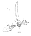
- FIG. 1 is a partially-exploded view of an embodiment of a propeller assembly
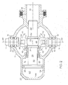
- FIG. 2 is cross-sectional view of an embodiment of a propeller assembly
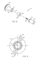
- FIG. 3 is an exploded view of an embodiment of an actuation shaft of the propeller assembly of FIG. 2 ;
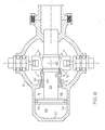
- FIG. 4 is a partial cross-sectional view of an embodiment of a propeller assembly
- FIG. 5 is a view of an embodiment of a propeller blade
- FIG. 6 is a cross-sectional view of another embodiment of a propeller assembly.
- the propeller assembly 10 includes a hub 12 which is receptive of a plurality of propeller blades 14 through a plurality of hub openings 16.
- the propeller assembly 10 is driven by a propeller shaft 18.
- a pitch change actuator 20 is operably connected to the plurality of propeller blades 14 to change the pitch of the propeller blades 14 during operation of the propeller assembly 10.
- FIG. 2 a cross-sectional view of an embodiment of the propeller assembly 10 is shown.
- the propeller shaft 18 is located at a propeller axis 22 which and drives rotation of the propeller assembly 10 about the propeller axis 22.
- An actuation shaft 24 is located in the hub 12 along the propeller axis 22 and is fixedly attached to an actuation piston 26 at one end of the actuation shaft 24.
- the actuation shaft 24 includes a spherical section 28 located between a first portion 30 and second portion 32 of the actuation shaft 24 between adjacent stop surfaces 34. As shown in FIG. 3 , in some embodiments, the spherical portion 28 includes a through hole 36 extending along the propeller axis 22.
- a pin 38 extends from the first portion 30 through the through hole 36 into the second portion 32 to secure the first portion 30, second portion 32 and spherical section 28 together forming the actuation shaft 24.
- the spherical section 28 may be formed from any suitable material, for example a hardened metal and/or wear resistant coating, or wear resistant composite material.
- At least one yoke 40 extends around the spherical section 28 and is supported thereon so as to permit articulation as indicated by arrows 42 within the confines of stop surfaces 34.
- the pitch change actuator piston 26 is slidably located in the pitch change actuator 20 such that linear motion of the piston 26 along the propeller axis 22 results in linear motion of the spherical section 28 and corresponding motion of the at least one yoke 40.
- the plurality of propeller blades 14 are rotably located in the propeller hub 12 and confined in the yoke 40 at a yoke channel 44 formed in the yoke 40, via suitable pin and roller assemblies 46 connected to the plurality of propeller blades 14. As shown in FIG. 4 , the pin and roller assemblies 46 are positioned offset in the yoke 40 such that translation of the yoke 40 along propeller axis 22 will result in rotation of blades 14 about a blade pitch change axis 48, and causes the plurality of rotor blades 14 to increase or decrease pitch in unison, this being well known in the art and commonly referred to as collective pitch change.
- motion of the yoke 40 about the spherical section 28 will also result in rotation of the propeller blade 14 about its pitch change axis 48.
- FIG. 2 it can be seen that motion of yoke 40 about spherical section 28 causes pitch change of opposite blades 14 in opposite directions.
- the yoke channel 44 is defined by two yoke bars 50 arranged in parallel, but other configurations which provide equivalent motion, for example a series of pins and links, may be utilized.
- Each propeller blade 14 extends outwardly from the hub 12 at the hub openings 16.
- Each propeller blade 14 is retained by one or more bearings 52 which allow for rotation of the propeller blade 14 about the pitch change axis 48, changing a pitch of the propeller blade 14.
- each pin and roller assembly 46 is located off-center at the propeller blade 14 relative to the pitch change axis 48. Because of this off-center position, a force applied to the pin and roller assembly 46 via the yoke 40 results in rotation of the propeller blade 14 about the pitch change axis 48.
- pitch of the propeller blades 14 is changed via axial movement of the yoke 40 along the propeller axis 22.
- This axial movement is achieved by changing a pressure in a portion of a pressure chamber 54.
- a pressure P f is increased in a shaft side 58 of the pressure chamber 54 to be greater than a pressure P c in an opposing side 60 of the pressure chamber 54. This results in an axial translation of the piston 26, and therefore the yoke 40, toward the first end 56.
- the pitch change can be reversed by increasing the pressure P c to be greater than P f to move the piston 26 away from the first end 56 thereby translating the yoke 40 away from the first end 56.
- the movement of the yoke 40 and pressurization change in portions of the pressure chamber 54 are achieved via addition and removal of hydraulic fluid from the pressure chamber 54, by activation of a flight control by the pilot. It is to be appreciated, however, that other means of moving the yoke 40, mechanical and/or electrical, may be used.
- Utilization of the spherical portion 28 increases the ability of the pitch of the propeller blades 14 to be adjusted as described earlier.
- Forces acting on the propeller blades 14 often vary as the propeller blades 14 rotate about the propeller axis 22, for example, when flow incident to the propeller blade 14 is non-parallel to the propeller axis 22.
- the yoke 40 is permitted to rotate about the yoke center 62 as shown by arrows 42. This freedom of rotation allows forces acting on the propeller blades 14 to change the pitch of the propeller blades 14 cyclically as the propeller blades 14 move around the propeller axis 22 being influenced cyclically by the variation in in-flow to the propeller 10.
- first propeller blade 14 As a first propeller blade 14 is subjected to greater forces than a second propeller blade 14, the forces drive a change in pitch in the first rotor blade 14. This, in turn, causes rotation of the yoke 40 about the yoke center 62 which changes the pitch of the second propeller blade 14 by an equal and opposite amount.
- the forces acting on the first propeller blade 14 change, and through the use of the spherical portion 28, so does the pitch of the first and second propeller blades 14.
- the spherical portion 28 effectively reduces the cyclical forces acting on the propeller blades 14 and reduces the moments on the propeller shaft 18, airframe, and other components due to the cyclical loading of the propeller blades 14.
- the propeller assembly 10 includes a yoke stop 64.
- the yoke stop 64 is a tubular piece located around the actuation shaft 24 at a shaft opening 66 in the hub 12 and is slidable therein.
- the yoke stop 64 when engaged, disables articulation of the yoke 40 about the spherical portion 28 of actuation shaft 24 thus stopping the cyclical pitch change in conditions when it is not desired, for example, low power approach and/or reversing conditions.
- the yoke stop 64 is engaged by increasing P f which forces the yoke stop 64 along the propeller axis 22 toward the yoke 40.
- the yoke stop 64 includes an engagement feature, in this embodiment, a stop ramp 68, which is engageable with a complimentary feature of the yoke 40, for example a yoke ramp 70.
- a stop ramp 68 engages with the yoke ramp 70 to prevent rotation of the yoke 40 about the yoke center 62.
- the yoke stop 64 is engaged only at low blade angles typically associated with low power and reverse because it is travel is limited by stop surface 72.
- P f is reduced to allowed movement of the yoke stop 64 away from the yoke 40.
- a return spring (not shown) may be used to assist in disengaging the yoke stop.
Landscapes
- Engineering & Computer Science (AREA)
- Aviation & Aerospace Engineering (AREA)
- Structures Of Non-Positive Displacement Pumps (AREA)
- Hydraulic Turbines (AREA)
Claims (14)
- Blattverstellsteuerungsmechanismus für eine Propellerbaugruppe (10), umfassend:eine ein kugelförmiges Element (28) beinhaltende Betätigungswelle (24), die auf einer Propellerachse (22) angeordnet ist; undeine Gabel (40), die um das kugelförmige Element (28) und um eine Gabelschwenkachse (62) im Wesentlichen lotrecht zur Propellerachse (22) drehbar darauf angeordnet ist, wobei die Gabel (40) eine Vielzahl von Propellerblattbefestigungen (44) beinhaltet, die jeweils angepasst sind, um ein Propellerblatt (14) aufzunehmen, wobei die Vielzahl von Blattbefestigungen (44) derart konfiguriert ist, dass die Rotation der Gabel (40) um die Gabelkippachse (62) eine Rotation jedes der Propellerblätter (14) um eine Blattverstellveränderungsachse (48) veranlasst.
- Blattverstellsteuerungsmechanismus nach Anspruch 1, wobei die Rotation der Gabel (40) um die Gabelkippachse (62) eine Rotation eines ersten Propellerblatts (14) der Vielzahl von Propellerblättern (14) in einer ersten Richtung und eine Rotation eines zweiten Propellerblatts (14) der Vielzahl von Propellerblättern (14) in einer zweiten Richtung veranlasst.
- Blattverstellsteuerungsmechanismus nach Anspruch 2, wobei die erste Richtung im Wesentlichen entgegengesetzt zur zweiten Richtung ist.
- Blattverstellsteuerungsmechanismus nach Anspruch 1, 2 oder 3, der einen Kolben (26) beinhaltet, der mit dem kugelförmigen Element (28) in Wirkverbindung steht und das kugelförmige Element (28) entlang der Propellerachse (22) verschieben kann.
- Blattverstellsteuerungsmechanismus nach Anspruch 4, wobei der Kolben (26) hydraulisch aktiviert wird.
- Blattverstellsteuerungsmechanismus nach Anspruch 1, 2, 3, 4 oder 5, der einen Gabelanschlag (64) beinhaltet, um bei Bedarf eine Rotation der Gabel (40) um die Gabelkippachse (62) zu verhindern.
- Blattverstellsteuerungsmechanismus nach Anspruch 6, wobei der Gabelanschlag (64) ein mechanischer Anschlag ist.
- Blattverstellsteuerungsmechanismus nach Anspruch 6, wobei der Gabelanschlag (64) hydraulisch aktiviert wird-
- Propellerbaugruppe (10), umfassend:eine Propellerwelle (18), die sich entlang einer Propellerachse (22) erstreckt;eine Vielzahl von Propellerblättern (14), die mit der Propellerwelle (18) in Wirkverbindung stehen; undeinen Blattverstellsteuerungsmechanismus nach einem der vorangehenden Ansprüche.
- Verfahren zur periodischen Neigungsveränderung einer Vielzahl von Propellerblättern (14) der Propellerbaugruppe (10), umfassend:Rotieren eines ersten Propellerblatts (14) der Vielzahl von Propellerblättern (14) um eine Blattverstellveränderungsachse (48) in Reaktion auf eine Strömungskraft, die auf das erste Propellerblatt (14) wirkt;Umsetzen der Rotation des ersten Propellerblatts (14) in eine Rotation einer Gabel (40) um eine Gabelkippachse (62) im Wesentlichen lotrecht zu einer Propellerachse (22) der Propellerbaugruppe (10);Rotieren eines zweiten Propellerblatts (14), das im Wesentlichen gegenüber vom ersten Propellerblatt (14) angeordnet ist, um die Blattverstellveränderungsachse (48) in Reaktion auf die Rotation der Gabel (40) um die Gabelkippachse (62).
- Verfahren nach Anspruch 10, wobei die Rotation des ersten Propellerblatts (14) in einer ersten Richtung verläuft und die Rotation des zweiten Propellerblatts (14) in einer zweiten Richtung im Wesentlichen entgegengesetzt zur ersten Richtung verläuft.
- Verfahren nach Anspruch 11, wobei die Gabel (40) auf einem kugelförmigen Element (28), das auf der Propellerachse (22) angeordnet ist, um die Gabelkippachse (62) rotiert.
- Verfahren nach Anspruch 12, das das Verschieben des kugelförmigen Elements (28) entlang der Propellerachse (22) durch Aktivieren eines Kolbens (26), der entlang der Propellerachse (22) angeordnet ist, beinhaltet.
- Verfahren nach Anspruch 10, 11, 12 oder 13, das bei Bedarf durch Eingreifen eines Gabelanschlags (64) das Verhindern einer Rotation der Gabel (40) um die Gabelkippachse (62) beinhaltet.
Applications Claiming Priority (1)
| Application Number | Priority Date | Filing Date | Title |
|---|---|---|---|
| US12/635,137 US8529205B2 (en) | 2009-12-10 | 2009-12-10 | Passive cyclic pitch control |
Publications (3)
| Publication Number | Publication Date |
|---|---|
| EP2332829A2 EP2332829A2 (de) | 2011-06-15 |
| EP2332829A3 EP2332829A3 (de) | 2014-06-18 |
| EP2332829B1 true EP2332829B1 (de) | 2015-12-09 |
Family
ID=43733159
Family Applications (1)
| Application Number | Title | Priority Date | Filing Date |
|---|---|---|---|
| EP10194631.7A Active EP2332829B1 (de) | 2009-12-10 | 2010-12-10 | Passive periodische Blattverstellsteuerung |
Country Status (2)
| Country | Link |
|---|---|
| US (1) | US8529205B2 (de) |
| EP (1) | EP2332829B1 (de) |
Families Citing this family (10)
| Publication number | Priority date | Publication date | Assignee | Title |
|---|---|---|---|---|
| FR2996591B1 (fr) * | 2012-10-04 | 2018-09-21 | Snecma | Dispositif de calage de pale d'une helice de turbomachine |
| FR3005096B1 (fr) * | 2013-04-29 | 2018-01-19 | Safran Aircraft Engines | Systeme pour commander le pas des pales d'une helice de turbomachine, et turbomachine a helice pour aeronef avec un tel systeme |
| JP6285500B2 (ja) * | 2015-07-08 | 2018-02-28 | ジーイー・アビエイション・システムズ・エルエルシー | ピッチ制御組立体及びプロペラ組立体並びにピッチを調整する方法 |
| US10077103B2 (en) * | 2016-03-18 | 2018-09-18 | Hamilton Sundstrand Corporation | Propeller pitch change actuation system |
| EP3241743B1 (de) | 2016-05-02 | 2018-12-26 | Ratier-Figeac SAS | Schaufelwinkelverstellungssteuerung |
| US10843790B2 (en) * | 2016-08-01 | 2020-11-24 | Kitty Hawk Corporation | Bistable pitch propeller system with bidirectional propeller rotation |
| FR3067415B1 (fr) * | 2017-06-13 | 2019-07-05 | Safran Aircraft Engines | Systeme de commande du calage des pales d'une helice d'une turbomachine |
| EP3882133A1 (de) | 2020-03-16 | 2021-09-22 | Ratier-Figeac SAS | Schaufelwinkelbetätigungsmechanismus |
| FR3161898A1 (fr) * | 2024-05-02 | 2025-11-07 | Safran Aircraft Engines | Procédé de modification d’un calage collectif et cyclique de pales pour une hélice de turbomachine |
| FR3161899A1 (fr) * | 2024-05-02 | 2025-11-07 | Safran Aircraft Engines | Système de calage collectif et cyclique de pales pour une hélice de turbomachine |
Family Cites Families (16)
| Publication number | Priority date | Publication date | Assignee | Title |
|---|---|---|---|---|
| US2422558A (en) * | 1941-09-15 | 1947-06-17 | Walter H Korff | Adjustable pitch propeller |
| US2640555A (en) * | 1946-03-01 | 1953-06-02 | Curtiss Wright Corp | Hydraulic propeller pitch-changing system |
| US2648391A (en) * | 1951-03-14 | 1953-08-11 | Curtiss Wright Corp | Articulated blade propeller |
| US3013615A (en) * | 1959-02-10 | 1961-12-19 | Karlstad Mekaniska Ab | Variable pitch propellers |
| US4037986A (en) * | 1975-09-04 | 1977-07-26 | Dowty Rotol Limited | Bladed rotors having control means for effecting blade pitch adjustment |
| US4473335A (en) * | 1981-06-19 | 1984-09-25 | Adroit Engineering Company | Helicopter hub system |
| US4422828A (en) * | 1981-10-09 | 1983-12-27 | Sambell Kenneth W | Method of and apparatus for increasing propulsive efficiency of aircraft propellers |
| US4591313A (en) * | 1983-12-30 | 1986-05-27 | The Boeing Company | Propeller pitch control system and apparatus |
| US5431539A (en) * | 1993-10-28 | 1995-07-11 | United Technologies Corporation | Propeller pitch change mechanism |
| US5836743A (en) * | 1997-10-22 | 1998-11-17 | United Technologies Corporation | Variable pitch counterweighted propeller system with releasable hydraulic pitchlock |
| US6077040A (en) * | 1998-05-01 | 2000-06-20 | United Technologies Corporation | Control system for blades for a variable pitch propeller |
| US6514044B2 (en) * | 2000-12-21 | 2003-02-04 | Hamilton Sundstrand Corporation | Offset crowned roller assembly for variable pitch propellers |
| US6511292B2 (en) * | 2001-06-27 | 2003-01-28 | Hamilton Sundstrand Corporation | Backup governing system for a variable pitch propeller |
| US6811376B2 (en) * | 2002-03-19 | 2004-11-02 | Hamilton Sundstrand | Actuation system for a controllable pitch propeller |
| US6981844B2 (en) * | 2003-10-08 | 2006-01-03 | Hamilton Sundstrand | Cyclic actuation system for a controllable pitch propeller and a method of providing aircraft control therewith |
| US7296969B2 (en) * | 2005-10-12 | 2007-11-20 | Hamilton Sundstrand Corporation | Propeller pitch change system |
-
2009
- 2009-12-10 US US12/635,137 patent/US8529205B2/en active Active
-
2010
- 2010-12-10 EP EP10194631.7A patent/EP2332829B1/de active Active
Also Published As
| Publication number | Publication date |
|---|---|
| US20110142646A1 (en) | 2011-06-16 |
| EP2332829A2 (de) | 2011-06-15 |
| US8529205B2 (en) | 2013-09-10 |
| EP2332829A3 (de) | 2014-06-18 |
Similar Documents
| Publication | Publication Date | Title |
|---|---|---|
| EP2332829B1 (de) | Passive periodische Blattverstellsteuerung | |
| US6981844B2 (en) | Cyclic actuation system for a controllable pitch propeller and a method of providing aircraft control therewith | |
| EP2557033B1 (de) | Modulares gegenläufigen Propeller-System | |
| CN108602552B (zh) | 用于锁定节距并用于使涡轮发动机螺旋桨顺桨的可调节节距风扇叶片的装置 | |
| EP2778061B1 (de) | Steuerungssystem für einen schwenkbarem Rotor mit zwei Anstiegs-/Abstiegsktuatoren | |
| US10220937B2 (en) | Multi-slice rotary electromechanical actuator | |
| EP0363997A2 (de) | Blattverstellsteuerung einer gegenläufigen Luftschraube | |
| EP1775213B1 (de) | Blattverstellsteuerung einer Luftschraube | |
| EP1832510A2 (de) | System zum Sperren der Verstellung eines Propellers | |
| EP2730505B1 (de) | Verhinderung der Drehung eines feststehenden Rings einer Taumelscheibe | |
| US10407163B2 (en) | Aircraft control system and method | |
| EP2774842B1 (de) | Propellerblatt mit relativ beweglichem Gegengewicht | |
| CA3083284C (en) | Pitch-change apparatus and method of pitching rotor blades | |
| GB2299562A (en) | Actuator for helicopter rotor blade aileron | |
| US9517839B2 (en) | Electromechanical linear actuator for in blade rotor control | |
| EP2343239B1 (de) | Verstellpropelleranordnung mit Drehmomentausgleich und Verfahren | |
| EP2340993B1 (de) | Neigungsverstellungsvorrichtung für Propelleranordnung | |
| EP2388484B1 (de) | Verriegelungsvorrichtung für einen Stellantrieb | |
| US8784055B2 (en) | Propeller pitchlock un-locking device | |
| EP3882133A1 (de) | Schaufelwinkelbetätigungsmechanismus | |
| EP3038911B1 (de) | Flugzeug mit an eine getriebegehäuseaussenseite gekoppeltem antriebselement | |
| EP2942273B1 (de) | Verstellringanordnung | |
| WO2022154684A1 (ru) | Несущий винт |
Legal Events
| Date | Code | Title | Description |
|---|---|---|---|
| PUAI | Public reference made under article 153(3) epc to a published international application that has entered the european phase |
Free format text: ORIGINAL CODE: 0009012 |
|
| AK | Designated contracting states |
Kind code of ref document: A2 Designated state(s): AL AT BE BG CH CY CZ DE DK EE ES FI FR GB GR HR HU IE IS IT LI LT LU LV MC MK MT NL NO PL PT RO RS SE SI SK SM TR |
|
| AX | Request for extension of the european patent |
Extension state: BA ME |
|
| PUAL | Search report despatched |
Free format text: ORIGINAL CODE: 0009013 |
|
| AK | Designated contracting states |
Kind code of ref document: A3 Designated state(s): AL AT BE BG CH CY CZ DE DK EE ES FI FR GB GR HR HU IE IS IT LI LT LU LV MC MK MT NL NO PL PT RO RS SE SI SK SM TR |
|
| AX | Request for extension of the european patent |
Extension state: BA ME |
|
| RIC1 | Information provided on ipc code assigned before grant |
Ipc: B64C 11/06 20060101AFI20140512BHEP Ipc: B64C 11/38 20060101ALI20140512BHEP |
|
| 17P | Request for examination filed |
Effective date: 20141218 |
|
| RBV | Designated contracting states (corrected) |
Designated state(s): AL AT BE BG CH CY CZ DE DK EE ES FI FR GB GR HR HU IE IS IT LI LT LU LV MC MK MT NL NO PL PT RO RS SE SI SK SM TR |
|
| GRAP | Despatch of communication of intention to grant a patent |
Free format text: ORIGINAL CODE: EPIDOSNIGR1 |
|
| INTG | Intention to grant announced |
Effective date: 20150623 |
|
| GRAS | Grant fee paid |
Free format text: ORIGINAL CODE: EPIDOSNIGR3 |
|
| GRAA | (expected) grant |
Free format text: ORIGINAL CODE: 0009210 |
|
| AK | Designated contracting states |
Kind code of ref document: B1 Designated state(s): AL AT BE BG CH CY CZ DE DK EE ES FI FR GB GR HR HU IE IS IT LI LT LU LV MC MK MT NL NO PL PT RO RS SE SI SK SM TR |
|
| REG | Reference to a national code |
Ref country code: GB Ref legal event code: FG4D |
|
| REG | Reference to a national code |
Ref country code: AT Ref legal event code: REF Ref document number: 764449 Country of ref document: AT Kind code of ref document: T Effective date: 20151215 Ref country code: CH Ref legal event code: EP |
|
| REG | Reference to a national code |
Ref country code: IE Ref legal event code: FG4D |
|
| REG | Reference to a national code |
Ref country code: DE Ref legal event code: R096 Ref document number: 602010029442 Country of ref document: DE Ref country code: FR Ref legal event code: PLFP Year of fee payment: 6 |
|
| REG | Reference to a national code |
Ref country code: LT Ref legal event code: MG4D |
|
| REG | Reference to a national code |
Ref country code: NL Ref legal event code: MP Effective date: 20151209 |
|
| PG25 | Lapsed in a contracting state [announced via postgrant information from national office to epo] |
Ref country code: ES Free format text: LAPSE BECAUSE OF FAILURE TO SUBMIT A TRANSLATION OF THE DESCRIPTION OR TO PAY THE FEE WITHIN THE PRESCRIBED TIME-LIMIT Effective date: 20151209 Ref country code: NO Free format text: LAPSE BECAUSE OF FAILURE TO SUBMIT A TRANSLATION OF THE DESCRIPTION OR TO PAY THE FEE WITHIN THE PRESCRIBED TIME-LIMIT Effective date: 20160309 Ref country code: LT Free format text: LAPSE BECAUSE OF FAILURE TO SUBMIT A TRANSLATION OF THE DESCRIPTION OR TO PAY THE FEE WITHIN THE PRESCRIBED TIME-LIMIT Effective date: 20151209 |
|
| REG | Reference to a national code |
Ref country code: AT Ref legal event code: MK05 Ref document number: 764449 Country of ref document: AT Kind code of ref document: T Effective date: 20151209 |
|
| PG25 | Lapsed in a contracting state [announced via postgrant information from national office to epo] |
Ref country code: LV Free format text: LAPSE BECAUSE OF FAILURE TO SUBMIT A TRANSLATION OF THE DESCRIPTION OR TO PAY THE FEE WITHIN THE PRESCRIBED TIME-LIMIT Effective date: 20151209 Ref country code: GR Free format text: LAPSE BECAUSE OF FAILURE TO SUBMIT A TRANSLATION OF THE DESCRIPTION OR TO PAY THE FEE WITHIN THE PRESCRIBED TIME-LIMIT Effective date: 20160310 Ref country code: NL Free format text: LAPSE BECAUSE OF FAILURE TO SUBMIT A TRANSLATION OF THE DESCRIPTION OR TO PAY THE FEE WITHIN THE PRESCRIBED TIME-LIMIT Effective date: 20151209 Ref country code: SE Free format text: LAPSE BECAUSE OF FAILURE TO SUBMIT A TRANSLATION OF THE DESCRIPTION OR TO PAY THE FEE WITHIN THE PRESCRIBED TIME-LIMIT Effective date: 20151209 Ref country code: FI Free format text: LAPSE BECAUSE OF FAILURE TO SUBMIT A TRANSLATION OF THE DESCRIPTION OR TO PAY THE FEE WITHIN THE PRESCRIBED TIME-LIMIT Effective date: 20151209 Ref country code: RS Free format text: LAPSE BECAUSE OF FAILURE TO SUBMIT A TRANSLATION OF THE DESCRIPTION OR TO PAY THE FEE WITHIN THE PRESCRIBED TIME-LIMIT Effective date: 20151209 Ref country code: BE Free format text: LAPSE BECAUSE OF NON-PAYMENT OF DUE FEES Effective date: 20151231 |
|
| PG25 | Lapsed in a contracting state [announced via postgrant information from national office to epo] |
Ref country code: IS Free format text: LAPSE BECAUSE OF FAILURE TO SUBMIT A TRANSLATION OF THE DESCRIPTION OR TO PAY THE FEE WITHIN THE PRESCRIBED TIME-LIMIT Effective date: 20151209 |
|
| PG25 | Lapsed in a contracting state [announced via postgrant information from national office to epo] |
Ref country code: IT Free format text: LAPSE BECAUSE OF FAILURE TO SUBMIT A TRANSLATION OF THE DESCRIPTION OR TO PAY THE FEE WITHIN THE PRESCRIBED TIME-LIMIT Effective date: 20151209 Ref country code: CZ Free format text: LAPSE BECAUSE OF FAILURE TO SUBMIT A TRANSLATION OF THE DESCRIPTION OR TO PAY THE FEE WITHIN THE PRESCRIBED TIME-LIMIT Effective date: 20151209 |
|
| REG | Reference to a national code |
Ref country code: CH Ref legal event code: PL |
|
| PG25 | Lapsed in a contracting state [announced via postgrant information from national office to epo] |
Ref country code: SK Free format text: LAPSE BECAUSE OF FAILURE TO SUBMIT A TRANSLATION OF THE DESCRIPTION OR TO PAY THE FEE WITHIN THE PRESCRIBED TIME-LIMIT Effective date: 20151209 Ref country code: EE Free format text: LAPSE BECAUSE OF FAILURE TO SUBMIT A TRANSLATION OF THE DESCRIPTION OR TO PAY THE FEE WITHIN THE PRESCRIBED TIME-LIMIT Effective date: 20151209 Ref country code: PT Free format text: LAPSE BECAUSE OF FAILURE TO SUBMIT A TRANSLATION OF THE DESCRIPTION OR TO PAY THE FEE WITHIN THE PRESCRIBED TIME-LIMIT Effective date: 20160411 Ref country code: IS Free format text: LAPSE BECAUSE OF FAILURE TO SUBMIT A TRANSLATION OF THE DESCRIPTION OR TO PAY THE FEE WITHIN THE PRESCRIBED TIME-LIMIT Effective date: 20160409 Ref country code: SM Free format text: LAPSE BECAUSE OF FAILURE TO SUBMIT A TRANSLATION OF THE DESCRIPTION OR TO PAY THE FEE WITHIN THE PRESCRIBED TIME-LIMIT Effective date: 20151209 Ref country code: AT Free format text: LAPSE BECAUSE OF FAILURE TO SUBMIT A TRANSLATION OF THE DESCRIPTION OR TO PAY THE FEE WITHIN THE PRESCRIBED TIME-LIMIT Effective date: 20151209 Ref country code: RO Free format text: LAPSE BECAUSE OF FAILURE TO SUBMIT A TRANSLATION OF THE DESCRIPTION OR TO PAY THE FEE WITHIN THE PRESCRIBED TIME-LIMIT Effective date: 20151209 |
|
| REG | Reference to a national code |
Ref country code: DE Ref legal event code: R097 Ref document number: 602010029442 Country of ref document: DE |
|
| REG | Reference to a national code |
Ref country code: IE Ref legal event code: MM4A |
|
| PG25 | Lapsed in a contracting state [announced via postgrant information from national office to epo] |
Ref country code: MC Free format text: LAPSE BECAUSE OF FAILURE TO SUBMIT A TRANSLATION OF THE DESCRIPTION OR TO PAY THE FEE WITHIN THE PRESCRIBED TIME-LIMIT Effective date: 20151209 |
|
| PLBE | No opposition filed within time limit |
Free format text: ORIGINAL CODE: 0009261 |
|
| STAA | Information on the status of an ep patent application or granted ep patent |
Free format text: STATUS: NO OPPOSITION FILED WITHIN TIME LIMIT |
|
| PG25 | Lapsed in a contracting state [announced via postgrant information from national office to epo] |
Ref country code: CH Free format text: LAPSE BECAUSE OF NON-PAYMENT OF DUE FEES Effective date: 20151231 Ref country code: IE Free format text: LAPSE BECAUSE OF NON-PAYMENT OF DUE FEES Effective date: 20151210 Ref country code: PL Free format text: LAPSE BECAUSE OF FAILURE TO SUBMIT A TRANSLATION OF THE DESCRIPTION OR TO PAY THE FEE WITHIN THE PRESCRIBED TIME-LIMIT Effective date: 20151209 Ref country code: DK Free format text: LAPSE BECAUSE OF FAILURE TO SUBMIT A TRANSLATION OF THE DESCRIPTION OR TO PAY THE FEE WITHIN THE PRESCRIBED TIME-LIMIT Effective date: 20151209 Ref country code: LI Free format text: LAPSE BECAUSE OF NON-PAYMENT OF DUE FEES Effective date: 20151231 |
|
| 26N | No opposition filed |
Effective date: 20160912 |
|
| REG | Reference to a national code |
Ref country code: FR Ref legal event code: PLFP Year of fee payment: 7 |
|
| PG25 | Lapsed in a contracting state [announced via postgrant information from national office to epo] |
Ref country code: SI Free format text: LAPSE BECAUSE OF FAILURE TO SUBMIT A TRANSLATION OF THE DESCRIPTION OR TO PAY THE FEE WITHIN THE PRESCRIBED TIME-LIMIT Effective date: 20151209 |
|
| PG25 | Lapsed in a contracting state [announced via postgrant information from national office to epo] |
Ref country code: BE Free format text: LAPSE BECAUSE OF FAILURE TO SUBMIT A TRANSLATION OF THE DESCRIPTION OR TO PAY THE FEE WITHIN THE PRESCRIBED TIME-LIMIT Effective date: 20151209 |
|
| PG25 | Lapsed in a contracting state [announced via postgrant information from national office to epo] |
Ref country code: HU Free format text: LAPSE BECAUSE OF FAILURE TO SUBMIT A TRANSLATION OF THE DESCRIPTION OR TO PAY THE FEE WITHIN THE PRESCRIBED TIME-LIMIT; INVALID AB INITIO Effective date: 20101210 Ref country code: BG Free format text: LAPSE BECAUSE OF FAILURE TO SUBMIT A TRANSLATION OF THE DESCRIPTION OR TO PAY THE FEE WITHIN THE PRESCRIBED TIME-LIMIT Effective date: 20151209 |
|
| PG25 | Lapsed in a contracting state [announced via postgrant information from national office to epo] |
Ref country code: CY Free format text: LAPSE BECAUSE OF FAILURE TO SUBMIT A TRANSLATION OF THE DESCRIPTION OR TO PAY THE FEE WITHIN THE PRESCRIBED TIME-LIMIT Effective date: 20151209 |
|
| PG25 | Lapsed in a contracting state [announced via postgrant information from national office to epo] |
Ref country code: HR Free format text: LAPSE BECAUSE OF FAILURE TO SUBMIT A TRANSLATION OF THE DESCRIPTION OR TO PAY THE FEE WITHIN THE PRESCRIBED TIME-LIMIT Effective date: 20151209 |
|
| PG25 | Lapsed in a contracting state [announced via postgrant information from national office to epo] |
Ref country code: MT Free format text: LAPSE BECAUSE OF FAILURE TO SUBMIT A TRANSLATION OF THE DESCRIPTION OR TO PAY THE FEE WITHIN THE PRESCRIBED TIME-LIMIT Effective date: 20151209 Ref country code: TR Free format text: LAPSE BECAUSE OF FAILURE TO SUBMIT A TRANSLATION OF THE DESCRIPTION OR TO PAY THE FEE WITHIN THE PRESCRIBED TIME-LIMIT Effective date: 20151209 |
|
| REG | Reference to a national code |
Ref country code: FR Ref legal event code: PLFP Year of fee payment: 8 |
|
| PG25 | Lapsed in a contracting state [announced via postgrant information from national office to epo] |
Ref country code: LU Free format text: LAPSE BECAUSE OF NON-PAYMENT OF DUE FEES Effective date: 20151210 |
|
| PG25 | Lapsed in a contracting state [announced via postgrant information from national office to epo] |
Ref country code: MK Free format text: LAPSE BECAUSE OF FAILURE TO SUBMIT A TRANSLATION OF THE DESCRIPTION OR TO PAY THE FEE WITHIN THE PRESCRIBED TIME-LIMIT Effective date: 20151209 |
|
| PG25 | Lapsed in a contracting state [announced via postgrant information from national office to epo] |
Ref country code: AL Free format text: LAPSE BECAUSE OF FAILURE TO SUBMIT A TRANSLATION OF THE DESCRIPTION OR TO PAY THE FEE WITHIN THE PRESCRIBED TIME-LIMIT Effective date: 20151209 |
|
| REG | Reference to a national code |
Ref country code: DE Ref legal event code: R082 Ref document number: 602010029442 Country of ref document: DE |
|
| P01 | Opt-out of the competence of the unified patent court (upc) registered |
Effective date: 20230522 |
|
| PGFP | Annual fee paid to national office [announced via postgrant information from national office to epo] |
Ref country code: DE Payment date: 20251126 Year of fee payment: 16 |
|
| PGFP | Annual fee paid to national office [announced via postgrant information from national office to epo] |
Ref country code: GB Payment date: 20251120 Year of fee payment: 16 |
|
| PGFP | Annual fee paid to national office [announced via postgrant information from national office to epo] |
Ref country code: FR Payment date: 20251120 Year of fee payment: 16 |