EP2332827A1 - Outboard motor antitheft apparatus - Google Patents
Outboard motor antitheft apparatus Download PDFInfo
- Publication number
- EP2332827A1 EP2332827A1 EP10194118A EP10194118A EP2332827A1 EP 2332827 A1 EP2332827 A1 EP 2332827A1 EP 10194118 A EP10194118 A EP 10194118A EP 10194118 A EP10194118 A EP 10194118A EP 2332827 A1 EP2332827 A1 EP 2332827A1
- Authority
- EP
- European Patent Office
- Prior art keywords
- information
- engine
- authentication
- ecu
- outboard motor
- Prior art date
- Legal status (The legal status is an assumption and is not a legal conclusion. Google has not performed a legal analysis and makes no representation as to the accuracy of the status listed.)
- Granted
Links
- 238000002485 combustion reaction Methods 0.000 claims description 7
- 238000000034 method Methods 0.000 claims description 7
- 239000007858 starting material Substances 0.000 description 4
- 238000010586 diagram Methods 0.000 description 3
- 238000009434 installation Methods 0.000 description 3
- 239000000470 constituent Substances 0.000 description 1
- 238000006073 displacement reaction Methods 0.000 description 1
- XLYOFNOQVPJJNP-UHFFFAOYSA-N water Substances O XLYOFNOQVPJJNP-UHFFFAOYSA-N 0.000 description 1
Images


Classifications
-
- B—PERFORMING OPERATIONS; TRANSPORTING
- B63—SHIPS OR OTHER WATERBORNE VESSELS; RELATED EQUIPMENT
- B63J—AUXILIARIES ON VESSELS
- B63J99/00—Subject matter not provided for in other groups of this subclass
-
- G—PHYSICS
- G07—CHECKING-DEVICES
- G07C—TIME OR ATTENDANCE REGISTERS; REGISTERING OR INDICATING THE WORKING OF MACHINES; GENERATING RANDOM NUMBERS; VOTING OR LOTTERY APPARATUS; ARRANGEMENTS, SYSTEMS OR APPARATUS FOR CHECKING NOT PROVIDED FOR ELSEWHERE
- G07C9/00—Individual registration on entry or exit
- G07C9/00174—Electronically operated locks; Circuits therefor; Nonmechanical keys therefor, e.g. passive or active electrical keys or other data carriers without mechanical keys
- G07C9/00309—Electronically operated locks; Circuits therefor; Nonmechanical keys therefor, e.g. passive or active electrical keys or other data carriers without mechanical keys operated with bidirectional data transmission between data carrier and locks
-
- B—PERFORMING OPERATIONS; TRANSPORTING
- B63—SHIPS OR OTHER WATERBORNE VESSELS; RELATED EQUIPMENT
- B63B—SHIPS OR OTHER WATERBORNE VESSELS; EQUIPMENT FOR SHIPPING
- B63B17/00—Vessels parts, details, or accessories, not otherwise provided for
- B63B2017/0009—Methods or devices specially adapted for preventing theft, or unauthorized use of vessels, or parts or accessories thereof, other than by using locks
-
- G—PHYSICS
- G07—CHECKING-DEVICES
- G07C—TIME OR ATTENDANCE REGISTERS; REGISTERING OR INDICATING THE WORKING OF MACHINES; GENERATING RANDOM NUMBERS; VOTING OR LOTTERY APPARATUS; ARRANGEMENTS, SYSTEMS OR APPARATUS FOR CHECKING NOT PROVIDED FOR ELSEWHERE
- G07C9/00—Individual registration on entry or exit
- G07C9/00174—Electronically operated locks; Circuits therefor; Nonmechanical keys therefor, e.g. passive or active electrical keys or other data carriers without mechanical keys
- G07C2009/00753—Electronically operated locks; Circuits therefor; Nonmechanical keys therefor, e.g. passive or active electrical keys or other data carriers without mechanical keys operated by active electrical keys
- G07C2009/00769—Electronically operated locks; Circuits therefor; Nonmechanical keys therefor, e.g. passive or active electrical keys or other data carriers without mechanical keys operated by active electrical keys with data transmission performed by wireless means
- G07C2009/00793—Electronically operated locks; Circuits therefor; Nonmechanical keys therefor, e.g. passive or active electrical keys or other data carriers without mechanical keys operated by active electrical keys with data transmission performed by wireless means by Hertzian waves
Definitions
- This invention relates to an outboard motor antitheft apparatus, particularly to an antitheft apparatus for a plurality of outboard motors to be installed on one boat.
- an antitheft apparatus for equipment like a vehicle having an internal combustion engine as a prime mover
- an immobilizer controller which, when an electronic key storing ID information is brought close thereto by the operator, sends the ID information to an immobilizer controller to verify it with authentication ID information, and only when the authentication is verified (the ID information is valid), allows the engine to be started with the electronic key, thereby preventing theft, as taught, for example, by Japanese Laid-Open Patent Application No. 2007-90908 .
- the equipment comprises a plurality of outboard motors installed on one boat, which is called the multiple outboard motor installation
- each outboard motor is equipped with the above antitheft apparatus
- the operator needs to carry and distinguish a plurality of the electronic keys, while repeating the similar checking operation several times. It requires additional work and hence, is troublesome.
- An object of this invention is therefore to overcome the aforesaid problem by providing an outboard motor antitheft apparatus that enables (the operator) to easily start a plurality of outboard motors installed on one boat and having their respective antitheft devices.
- this invention provides in its first aspect an apparatus for preventing theft of outboard motors adapted to be mounted on a stem of a boat, each of the outboard motors having an internal combustion engine and an engine controller for controlling operation of the engine, comprising: an authenticator that is installed in each of the outboard motors and that acquires ID information from an electronic key when the key is brought close thereto by an operator, compares the acquired ID information with authentication ID information, and gives permission to the engine controller to start the engine when it is determined that the acquired ID information corresponds with the authentication ID information, wherein the authenticator communicates with the engine controller of other of the outboard motors to notify that the permission to start the engine was given.
- this invention provides in its second aspect a method for preventing theft of outboard motors adapted to be mounted on a stem of a boat, each of the outboard motors having an internal combustion engine and an engine controller for controlling operation of the engine, comprising the steps of: acquiring ID information from an electronic key when the key is brought close thereto by an operator, comparing the acquired ID information with authentication ID information, giving permission to the engine controller to start the engine when it is determined that the acquired ID information corresponds with the authentication ID information, and communicating with the engine controller of other of the outboard motors to notify that the permission to start the engine was given.
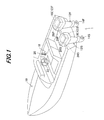
- FIG. 1 is an overall schematic view of an outboard motor antitheft apparatus including a boat (hull) according to an embodiment of the invention
- symbol 1 indicates an outboard motor antitheft apparatus.
- a plurality of, i.e., two outboard motors 12 are clamped (fastened) to the stem or transom of a boat (hull) 10, which is called the “multiple outboard motor installation.”
- the outboard motors 12 comprise a group of outboard motors to be installed on the one boat 10.
- the starboard side outboard motor i.e., outboard motor on the right side when looking in the direction of forward travel is called a first outboard motor and designated by 12F
- the port side outboard motor i.e., outboard motor on the left side a second outboard motor and designated by 12S.
- Constituent members of the first outboard motor 12F and that of the second outboard motor 12S below are suffixed by "F" and "S,” respectively.
- the first and second outboard motors 12F, 12S are equipped with propellers 14F, 14S and internal combustion engines 16F, 16S.
- the propellers 14F, 14S are rotated by power transmitted from the engines 16F, 16S and produce thrust for propelling the boat 10.
- Each of the engines 16F, 16S comprises a spark-ignition gasoline engine with a displacement of 2,200 cc.
- the engines 16F, 16S are located above the water surface and covered by engine covers.
- a remote control box 18 is installed near a cockpit or operator's seat of the boat 10.
- the remote control box 18 is equipped with a lever 20 to be operable by the operator.
- the lever 20 can be moved (swung) fore and aft, i.e., toward and away from the operator from its initial position, by which the operator can input shift (gear) position commands and engine speed regulation commands.
- a lever position sensor (not shown) is installed near the lever 20 and produces an output or signal corresponding to a position of the operated lever 20.
- a steering wheel 22 is installed near the cockpit to be rotatably manipulated. The operator manipulates the steering wheel 22 to input steering or turning commands.
- a steering angle sensor (not shown) is installed at a rotary shaft of the steering wheel 22 and produces an output or signal indicative of steering angle of the steering wheel 22.
- the first and second outboard motors 12F, 12S are installed near the engines 16F, 16S with Electronic Control Units (hereinafter called the "engine ECUs” or “engine controller”) 24F, 24S that control the operation of the engines 16F, 16S and other components of the outboard motors 12F, 12S, respectively.
- Each of the engine ECUs 24F, 24S comprises a microcomputer having a CPU, ROM, memory, input/output circuit and the like.
- the outputs of the forgoing sensors are inputted to the engine ECUs 24F, 24S, separately. Based on the inputted outputs, the engine ECUs 24F, 24S control the operation of the engines 16F, 16S and other components of the outboard motors 12F, 12S in accordance with programs stored in the ROMs.
- the first and second outboard motors 12F, 12S are also installed near the engine ECUs 24F, 24S with other Electronic Control Units (hereinafter called the "authentication ECUs” or “authenticator”) 26F, 26S that perform authentication check of electronic keys so as to prevent the outboard motors from theft.
- Each of the authentication ECUs 26F, 26S similarly comprises a microcomputer having a CPU, ROM, memory, input/output circuit and the like.
- the authentication ECU 26F, 26S Upon the manipulation of an electronic key, the authentication ECU 26F, 26S acquires ID information stored in the key, determines whether the acquired ID information corresponds with authentication ID information of the outboard motor 12F, 12S, and when they are determined to correspond with each other, allows the engine 16F, 16S of the outboard motor 12F, 12S to start.
- the engine ECUs 24F, 24S and authentication ECUs 26F, 26S are activated upon the supply of power from a battery disposed in the first and second outboard motors 12F, 12S or the boat 10.
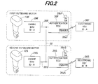
- FIG. 2 is a block diagram showing the configuration of the engine ECUs 24F, 24S and authentication ECUs 26F, 26S of the outboard motors 12F, 12S.
- the engine ECU 24F and authentication ECU 26F are interconnected to communicate with each other by a communication line (first wire) 28F.
- the engine ECU 24F stores ID information A (authentication ID information; indicated by "ID: A” in the drawing) used to identify the engine 16F of the first outboard motor 12F.
- ID information comprises a string of several characters.
- a card-shaped electronic key 30F for the first outboard motor 12F stores the ID information A (indicated by "ID: A") which is the same as that stored in the engine ECU 24F.
- the authentication ECU 26F is equipped with a reader 26aF.
- the authentication ECU 26F can acquire the ID information A from the key 30F through the reader 26aF by wireless communication (more precisely, the contactless-type short-distance wireless communication).
- the authentication ECU 26F verifies the acquired ID information A of the key 30F with the ID information A of the engine 16F of the first outboard motor 12F sent through the communication line 28F.
- the authentication ECU 26F sends an enable signal to the engine ECU 24F, whereby the engine ECU 24F makes the engine 16F ready for start, more exactly, enables the ignition. Under this condition, when a starter switch 26bF associated with the authentication ECU 26F is made ON, the engine 16F is started.
- the authentication ECU 26F determines in its authentication operation that the ID information acquired from an electronic key does not correspond with the ID information A of the engine 16F, the authentication ECU 26F does not send the enable signal to the engine ECU 24F. Consequently, since the ignition is not enabled, even when the starter switch 26bF is made ON, the engine 16F is not started.
- the same configuration is applied to the second outboard motor 12S.
- the engine ECU 24S and authentication ECU 26S are interconnected by a communication line (first line) 28S.
- the engine ECU 24S stores ID information B (authentication ID information; indicated by "ID: B") used to identify the engine 16S of the second outboard motor 12S.
- An electronic key 30S for the second outboard motor 12S stores the ID information B (indicated by "ID: B") which is the same as that stored in the engine ECU 24S.
- the authentication ECU 26S can acquire the ID information B from the key 30S through a reader 26aS by wireless communication.
- the authentication ECU 26S verifies the acquired ID information B of the key 30S with the ID information B of the engine 16S of the second outboard motor 12S sent through the communication line 28S.
- the authentication ECU 26S sends the enable signal to the engine ECU 24S, whereby the engine ECU 24S makes the engine 16S ready for start, more exactly, enables the ignition. Under this condition, when a starter switch 26bS associated with the authentication ECU 26S is made ON by the operator, the engine 16S is started.
- the authentication ECU 26S determines that the ID information acquired from an electronic key 30 does not correspond with the ID information B of the engine 16S, the authentication ECU 26S does not send the enable signal to the engine ECU 24S. Consequently, since the ignition is not enabled even when the starter switch 26bS is made ON by the operator, the engine 16S is not started.
- the first (second) outboard motor 12F (12S) is configured such that, when the authentication ECU 26F (26S) determines that the ID information A (B) in the key 30F (30S) corresponds with the authentication ID information A (B) in the engine ECU 24F (24S), the engine start is enabled or allowed and when the two data of ID information do not correspond with each other, the engine start is disabled, thereby preventing theft of the outboard motor 12F (12S) and the boat 10.
- the apparatus 1 is characterized in that, as illustrated, a connecting line (second wire) 32 is provide which connects the communication line 28F of the first outboard motor 12F with the communication line 28S of the second outboard motor 12S, and vice versa.
- a connecting line (second wire) 32 is provide which connects the communication line 28F of the first outboard motor 12F with the communication line 28S of the second outboard motor 12S, and vice versa.
- the authentication ECU 26F of the first outboard motor 12F and the engine ECU 24S of the second outboard motor 12S can communicate with each other.
- the first and second outboard motors 12F, 12S can exchange their information related to authentication through the connecting line 32, thereby facilitating the starting operation of the outboard motors 12F, 12S.
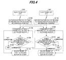
- FIG. 3 is a flowchart showing the operation of the apparatus 1 for starting the engines 16F, 16S of the first and second outboard motors 12F, 12S.
- the authentication ECU 26F communicates with the engine ECU 24F of the first outboard motor 12F and in S14, the authentication ECU 26F verifies or compares the ID information A of the key 30F with the ID information A of the first outboard motor 12F stored in the engine ECU 24F.
- the authentication is verified and the program proceeds to S16, in which the authentication ECU 26F allows the engine 16F to start (gives permission to the engine ECU 24F to start the engine 16F), while proceeding to S 18, in which the authentication ECU 26F communicates with the engine ECU 24S of the second outboard motor 12S through the connecting line 32, so that the authentication ECU 26F sends authentication-verified information of the first outboard motor 12F to the engine ECU 24S (to notify that the permission to start the engine 16F was given).
- the authentication ECU 26F also allows the engine 16S of the second outboard motor 12S to start (more precisely, based on the sent authentication-verified information of the first outboard motor 12F, the engine ECU 24S makes the engine 16S ready for start).
- the program also proceeds to S 18, in which the authentication ECU 26F communicates with the engine ECU 24S of the second outboard motor 12S through the connecting line 32, and to S22, in which the authentication ECU 26F verifies the ID information A of the key 30F with the ID information B of the second outboard motor 12S stored in the engine ECU 24S.
- the program proceeds to S24 to be terminated.
- the authentication ECU 26S communicates with the engine ECU 24S and in S22, the authentication ECU 26S verifies the ID information B of the key 30S with the ID information B of the second outboard motor 12S stored in the engine ECU 24S.
- the authentication is verified and the program proceeds to S20, in which the authentication ECU 26S allows the engine 16S to start, while proceeding to S12, in which the authentication ECU 26S communicates with the engine ECU 24F of the first outboard motor 12F through the connecting line 32, so that the authentication ECU 26S sends authentication-verified information of the second outboard motor 12S to the engine ECU 24F. Then, in S16, the authentication ECU 26S also allows the engine 16F of the first outboard motor 12F to start.
- the program also proceeds to S12, in which the authentication ECU 26S communicates with the engine ECU 24F of the first outboard motor 12F through the connecting line 32, and to S14, in which the authentication ECU 26S verifies the ID information B of the key 30S with the ID information A of the first outboard motor 12F stored in the engine ECU 24F.
- S12 in which the authentication ECU 26S communicates with the engine ECU 24F of the first outboard motor 12F through the connecting line 32
- S14 in which the authentication ECU 26S verifies the ID information B of the key 30S with the ID information A of the first outboard motor 12F stored in the engine ECU 24F.
- the program proceeds to S28 to be terminated.
- the authentication ECU 26F (26S) of the first (second) outboard motor 12F (12S) determines that the authentication for starting the engine 16F (16S) is verified, it makes the engine 16F (16S) ready for start, while transmitting the authentication-verified information to the engine ECU 24S (24F) of the second (first) outboard motor 12S (12F) to make the engine 16S (16F) ready for start.
- each of the first and second outboard motors 12F, 12S is equipped with an antitheft device (such as the authentication ECU 26) separately, the authentication operation of only either one of the outboard motors 12F, 12S can make the both outboard motors 12F, 12S (more exactly, the engines 16F, 16S thereof) ready for start, thereby easily starting the outboard motors 12F, 12S.
- an antitheft device such as the authentication ECU 26
- FIG. 4 is a flowchart similar to FIG. 3 but showing the operation of the apparatus 1 for starting the engines 16F, 16S. What is different from FIG. 3 is that, in FIG. 4 , the key 30S for the second outboard motor 12S is brought close to the authentication ECU 26F of the first outboard motor 12F and vice versa. In other words, the remaining configuration is the same as that of FIG. 3 .
- the authentication ECU 26F communicates with the engine ECU 24F of the first outboard motor 12F and in S104, the authentication ECU 26F verifies or compares the ID information B of the key 30S with the ID information A of the first outboard motor 12F stored in the engine ECU 24F. In this case, since the two data of the ID information B, A do not correspond with each other, the program proceeds to S 106 to be terminated.
- the program also proceeds to S108, in which the authentication ECU 26F communicates with the engine ECU 24S of the second outboard motor 12S through the connecting line 32, and to S110, in which the authentication ECU 26F verifies the ID information B of the key 30S with the ID information B of the second outboard motor 12S stored in the engine ECU 24S.
- the authentication ECU 26F of the first outboard motor 12F allows the engine 16S of the second outboard motor 12S to start through the engine ECU 24S thereof (gives permission to the engine ECU 24S to start the engine 16S), while proceeding to S102, in which the authentication ECU 26F communicates with the engine ECU 24F, so that the authentication ECU 26F sends authentication-verified information of the second outboard motor 12S to the engine ECU 24F (to notify that the permission to start the engine 16F was given).
- the authentication ECU 26F also allows the engine 16F of the first outboard motor 12F to start.
- the authentication ECU 26S communicates with the engine ECU 24S of the second outboard motor 12S and in S110, the authentication ECU 26S verifies the ID information A of the key 30F with the ID information B of the second outboard motor 12S stored in the engine ECU 24S. In this case, since the two data of the ID information A, B do not correspond with each other, the program proceeds to S 118 to be terminated.
- the program also proceeds to S102, in which the authentication ECU 26S communicates with the engine ECU 24F of the first outboard motor 12F through the connecting line 32, and to S104, in which the authentication ECU 26S verifies the ID information A of the key 30F with the ID information A of the first outboard motor 12F stored in the engine ECU 24F.
- the authentication is verified and the program proceeds to S114, in which the authentication ECU 26S of the second outboard motor 12S allows the engine 16F of the first outboard motor 12F to start through the engine ECU 24F thereof, while proceeding to S108, in which the authentication ECU 26S communicates with the engine ECU 24S, so that the authentication ECU 26S sends authentication-verified information of the first outboard motor 12F to the engine ECU 24S. Then, in S112, the authentication ECU 26S also allows the engine 16S of the second outboard motor 12S to start.
- the authentication ECU 26F (26S) of the first (second) outboard motor 12F (12S) determines that the authentication for starting the engine 16F (16S) is not verified, it communicates with the second (first) outboard motor 12S (12F) (i.e., the other outboard motor) through the connecting line 32 and when the ID information B (A) acquired from the key 30S (30F) corresponds with the authentication ID information B (A) in the engine ECU 24S (24F), makes the both outboard motors 12F, 12S (more exactly, the engines 16F, 16S thereof) ready for start.
- the embodiment is configured to have an apparatus (1) and method for preventing theft of outboard motors (12F, 12S) adapted to be mounted on a stem of a boat (10), each of the outboard motors having an internal combustion engine (16F, 16S) and an engine controller (engine ECU 24F, 24S) for controlling operation of the engine, characterized by: an authenticator (authentication ECU 26F, 26S) that is installed in each of the outboard motors (12F, 12S) and that acquires ID information (A, B) from an electronic key (30F, 30S) when the key is brought close thereto by an operator (S10, S100; S26, S116), compares the acquired ID information (A, B) with authentication ID information (S 14, S104; S22, S110), and gives permission to the engine controller (24F, 24S) to start the engine when it is determined that the acquired ID information corresponds with the authentication ID information (S16, S 114; S20, S112), and the authenticator (26F, 26S) communicates with the
- the engine controller (engine ECU) of the other outboard motor allows the engine thereof to start.
- the engine controller (engine ECU) of the other outboard motor allows the engine thereof to start.
- the operator carries either one of the electronic keys for the outboard motors and the authentication operation of only one of the outboard motors can make all the outboard motors ready for start, thereby easily starting a plurality of the outboard motors.
- the authenticator (26F, 26S) communicates with other of the outboard motors (12S, 12F) such that the authenticator (26F, 26S) compares the acquired ID information (B, A) with authentication ID information of the other outboard motor (12S, 12F) and gives the permission to the engine controllers (24S, 24F) to start the engines (16S, 16F) when it is determined that the acquired ID information corresponds with the authentication ID information (S100, S108, S110, S112; S116, S102, S104, S114).
- the one outboard motor communicates with the other of the outboard motors and when the acquired ID information corresponds with the ID information stored in the other, all the outboard motors are made ready for start. With this, it becomes possible to more easily start a plurality of the outboard motors.
- the engine controller (24F, 24S) and the authenticator (26F, 26S) of each of the outboard motors (12F, 12S) are connected by a first wire (28F, 28S) and each of the first wire is connected by a second wire (32) such that the authenticator communicates with the engine controller of other of the outboard motors through the second wire.
- the other authentication unit can be used to make all the outboard motors ready for start.
- the wireless communication may be used in place of the connecting line 32.
- the electronic key 30 is adapted to store the two data of the ID information A, B for the first and second outboard motors 12F, 12S.
- each of the outboard motors having an engine and an engine controller, and an authenticator that acquires ID information from an electronic key when the key is brought close thereto by an operator, and gives permission to the engine controller to start the engine when the acquired ID information corresponds with the authentication ID information, and communicates with the engine controller of other outboard motor to notify that the permission to start the engine was given, thereby enabling the operator to easily start the outboard motors installed on one boat and having their respective authenticators.
Landscapes
- Engineering & Computer Science (AREA)
- Chemical & Material Sciences (AREA)
- Combustion & Propulsion (AREA)
- Mechanical Engineering (AREA)
- Ocean & Marine Engineering (AREA)
- Computer Networks & Wireless Communication (AREA)
- Physics & Mathematics (AREA)
- General Physics & Mathematics (AREA)
- Combined Controls Of Internal Combustion Engines (AREA)
- Lock And Its Accessories (AREA)
- Burglar Alarm Systems (AREA)
Abstract
Description
- This invention relates to an outboard motor antitheft apparatus, particularly to an antitheft apparatus for a plurality of outboard motors to be installed on one boat.
- Conventionally, an antitheft apparatus (so-called an "immobilizer") for equipment like a vehicle having an internal combustion engine as a prime mover is known which, when an electronic key storing ID information is brought close thereto by the operator, sends the ID information to an immobilizer controller to verify it with authentication ID information, and only when the authentication is verified (the ID information is valid), allows the engine to be started with the electronic key, thereby preventing theft, as taught, for example, by Japanese Laid-Open Patent Application No.
2007-90908 - However, for instance, in the case where the equipment comprises a plurality of outboard motors installed on one boat, which is called the multiple outboard motor installation, and each outboard motor is equipped with the above antitheft apparatus, it is necessary for the operator to separately manipulate electronic keys associated with the outboard motors for starting all the outboard motors. Specifically, in order to start all the outboard motors, the operator needs to carry and distinguish a plurality of the electronic keys, while repeating the similar checking operation several times. It requires additional work and hence, is troublesome.
- An object of this invention is therefore to overcome the aforesaid problem by providing an outboard motor antitheft apparatus that enables (the operator) to easily start a plurality of outboard motors installed on one boat and having their respective antitheft devices.
- In order to achieve the object, this invention provides in its first aspect an apparatus for preventing theft of outboard motors adapted to be mounted on a stem of a boat, each of the outboard motors having an internal combustion engine and an engine controller for controlling operation of the engine, comprising: an authenticator that is installed in each of the outboard motors and that acquires ID information from an electronic key when the key is brought close thereto by an operator, compares the acquired ID information with authentication ID information, and gives permission to the engine controller to start the engine when it is determined that the acquired ID information corresponds with the authentication ID information, wherein the authenticator communicates with the engine controller of other of the outboard motors to notify that the permission to start the engine was given.
- In order to achieve the object, this invention provides in its second aspect a method for preventing theft of outboard motors adapted to be mounted on a stem of a boat, each of the outboard motors having an internal combustion engine and an engine controller for controlling operation of the engine, comprising the steps of: acquiring ID information from an electronic key when the key is brought close thereto by an operator, comparing the acquired ID information with authentication ID information, giving permission to the engine controller to start the engine when it is determined that the acquired ID information corresponds with the authentication ID information, and communicating with the engine controller of other of the outboard motors to notify that the permission to start the engine was given.
- The above and other objects and advantages of the invention will be more apparent from the following description and drawings in which:
-
FIG. 1 is an overall schematic view of an outboard motor antitheft apparatus including a boat (hull) according to an embodiment of the invention; -
FIG. 2 is a block diagram showing the configuration of the apparatus shown inFIG. 1 ; -
FIG. 3 is a flowchart showing the operation of the apparatus shown inFIG. 2 for starting engines of first outboard motor and second outboard motor; -
FIG. 4 is a flowchart similar toFIG. 3 but showing another operation of the apparatus shown inFIG. 2 for starting the engines of the first outboard motor and second outboard motor; and -
FIG. 5 is a block diagram similar toFIG. 2 but showing the configuration of the apparatus shown inFIG. 1 . - An outboard motor antitheft apparatus according to an embodiment of the invention will now be explained with reference to the attached drawings.
-
FIG. 1 is an overall schematic view of an outboard motor antitheft apparatus including a boat (hull) according to an embodiment of the invention; - In
FIG. 1 , symbol 1 indicates an outboard motor antitheft apparatus. As illustrated, a plurality of, i.e., twooutboard motors 12 are clamped (fastened) to the stem or transom of a boat (hull) 10, which is called the "multiple outboard motor installation." In other words, theoutboard motors 12 comprise a group of outboard motors to be installed on the oneboat 10. In the following, the starboard side outboard motor, i.e., outboard motor on the right side when looking in the direction of forward travel is called a first outboard motor and designated by 12F, while the port side outboard motor, i.e., outboard motor on the left side a second outboard motor and designated by 12S. Constituent members of thefirst outboard motor 12F and that of thesecond outboard motor 12S below are suffixed by "F" and "S," respectively. - The first and
second outboard motors propellers propellers boat 10. Each of the engines 16F, 16S comprises a spark-ignition gasoline engine with a displacement of 2,200 cc. The engines 16F, 16S are located above the water surface and covered by engine covers. - A
remote control box 18 is installed near a cockpit or operator's seat of theboat 10. Theremote control box 18 is equipped with alever 20 to be operable by the operator. Thelever 20 can be moved (swung) fore and aft, i.e., toward and away from the operator from its initial position, by which the operator can input shift (gear) position commands and engine speed regulation commands. A lever position sensor (not shown) is installed near thelever 20 and produces an output or signal corresponding to a position of the operatedlever 20. - A
steering wheel 22 is installed near the cockpit to be rotatably manipulated. The operator manipulates thesteering wheel 22 to input steering or turning commands. A steering angle sensor (not shown) is installed at a rotary shaft of thesteering wheel 22 and produces an output or signal indicative of steering angle of thesteering wheel 22. - The first and
second outboard motors outboard motors engine ECUs engine ECUs engine ECUs outboard motors - Details of the outboard motor are described in Japanese Laid-Open Patent Application No.
2006-142880 - The first and
second outboard motors engine ECUs authentication ECUs authentication ECU outboard motor outboard motor - The
engine ECUs authentication ECUs second outboard motors boat 10. -
FIG. 2 is a block diagram showing the configuration of theengine ECUs authentication ECUs outboard motors - In the
first outboard motor 12F, the engine ECU 24F andauthentication ECU 26F are interconnected to communicate with each other by a communication line (first wire) 28F. The engine ECU 24F stores ID information A (authentication ID information; indicated by "ID: A" in the drawing) used to identify the engine 16F of thefirst outboard motor 12F. The ID information comprises a string of several characters. - A card-shaped
electronic key 30F for thefirst outboard motor 12F stores the ID information A (indicated by "ID: A") which is the same as that stored in the engine ECU 24F. - The
authentication ECU 26F is equipped with a reader 26aF. When the key 30F is brought close to theauthentication ECU 26F of thefirst outboard motor 12F by the operator, theauthentication ECU 26F can acquire the ID information A from the key 30F through the reader 26aF by wireless communication (more precisely, the contactless-type short-distance wireless communication). Theauthentication ECU 26F verifies the acquired ID information A of the key 30F with the ID information A of the engine 16F of thefirst outboard motor 12F sent through thecommunication line 28F. - In this case, since the above two data of the ID information A correspond with each other, the authentication ECU 26F sends an enable signal to the engine ECU 24F, whereby the engine ECU 24F makes the engine 16F ready for start, more exactly, enables the ignition. Under this condition, when a starter switch 26bF associated with the
authentication ECU 26F is made ON, the engine 16F is started. - On the other hand, when the
authentication ECU 26F determines in its authentication operation that the ID information acquired from an electronic key does not correspond with the ID information A of the engine 16F, theauthentication ECU 26F does not send the enable signal to theengine ECU 24F. Consequently, since the ignition is not enabled, even when the starter switch 26bF is made ON, the engine 16F is not started. - The same configuration is applied to the
second outboard motor 12S. Specifically, theengine ECU 24S andauthentication ECU 26S are interconnected by a communication line (first line) 28S. The engine ECU 24S stores ID information B (authentication ID information; indicated by "ID: B") used to identify the engine 16S of thesecond outboard motor 12S. - An
electronic key 30S for thesecond outboard motor 12S stores the ID information B (indicated by "ID: B") which is the same as that stored in the engine ECU 24S. - When the key 30S is brought close to the
authentication ECU 26S of thesecond outboard motor 12S by the operator, theauthentication ECU 26S can acquire the ID information B from the key 30S through a reader 26aS by wireless communication. Theauthentication ECU 26S verifies the acquired ID information B of the key 30S with the ID information B of the engine 16S of thesecond outboard motor 12S sent through thecommunication line 28S. - Since the above two data of the ID information B correspond with each other, the authentication ECU 26S sends the enable signal to the engine ECU 24S, whereby the engine ECU 24S makes the engine 16S ready for start, more exactly, enables the ignition. Under this condition, when a starter switch 26bS associated with the
authentication ECU 26S is made ON by the operator, the engine 16S is started. - On the other hand, when the
authentication ECU 26S determines that the ID information acquired from an electronic key 30 does not correspond with the ID information B of the engine 16S, theauthentication ECU 26S does not send the enable signal to theengine ECU 24S. Consequently, since the ignition is not enabled even when the starter switch 26bS is made ON by the operator, the engine 16S is not started. - Thus, the first (second)
outboard motor 12F (12S) is configured such that, when theauthentication ECU 26F (26S) determines that the ID information A (B) in the key 30F (30S) corresponds with the authentication ID information A (B) in theengine ECU 24F (24S), the engine start is enabled or allowed and when the two data of ID information do not correspond with each other, the engine start is disabled, thereby preventing theft of theoutboard motor 12F (12S) and theboat 10. - The apparatus 1 according to this embodiment is characterized in that, as illustrated, a connecting line (second wire) 32 is provide which connects the
communication line 28F of the firstoutboard motor 12F with thecommunication line 28S of the secondoutboard motor 12S, and vice versa. Owing to this configuration, theauthentication ECU 26F of the firstoutboard motor 12F and theengine ECU 24S of the secondoutboard motor 12S can communicate with each other. In other words, the first and secondoutboard motors line 32, thereby facilitating the starting operation of theoutboard motors -
FIG. 3 is a flowchart showing the operation of the apparatus 1 for starting the engines 16F, 16S of the first and secondoutboard motors - First, in S10, when the key 30F having the ID information A for the first
outboard motor 12F is brought close to the reader 26aF of theauthentication ECU 26F of the firstoutboard motor 12F by the operator, theauthentication ECU 26F acquires the ID information A from the key 30F. - Next, in S12, the
authentication ECU 26F communicates with theengine ECU 24F of the firstoutboard motor 12F and in S14, theauthentication ECU 26F verifies or compares the ID information A of the key 30F with the ID information A of the firstoutboard motor 12F stored in theengine ECU 24F. - Since the two data of the ID information A correspond with each other, the authentication is verified and the program proceeds to S16, in which the
authentication ECU 26F allows the engine 16F to start (gives permission to theengine ECU 24F to start the engine 16F), while proceeding toS 18, in which theauthentication ECU 26F communicates with theengine ECU 24S of the secondoutboard motor 12S through the connectingline 32, so that theauthentication ECU 26F sends authentication-verified information of the firstoutboard motor 12F to theengine ECU 24S (to notify that the permission to start the engine 16F was given). - Then, in S20, the
authentication ECU 26F also allows the engine 16S of the secondoutboard motor 12S to start (more precisely, based on the sent authentication-verified information of the firstoutboard motor 12F, theengine ECU 24S makes the engine 16S ready for start). - Further, after S10 in which the
authentication ECU 26F acquires the ID information A from the key 30F as mentioned above, the program also proceeds toS 18, in which theauthentication ECU 26F communicates with theengine ECU 24S of the secondoutboard motor 12S through the connectingline 32, and to S22, in which theauthentication ECU 26F verifies the ID information A of the key 30F with the ID information B of the secondoutboard motor 12S stored in theengine ECU 24S. In this case, since the two data of the ID information A, B do not correspond with each other, the program proceeds to S24 to be terminated. - The above operation is similarly conducted when the key 30S is brought close to the
authentication ECU 26S of the secondoutboard motor 12S. - Specifically, in S26, when the key 30S having the ID information B for the second
outboard motor 12S is brought close to the reader 26aS of theauthentication ECU 26S of the secondoutboard motor 12S by the operator, theauthentication ECU 26S acquires the ID information B from the key 30S. - Next, in S18, the
authentication ECU 26S communicates with theengine ECU 24S and in S22, theauthentication ECU 26S verifies the ID information B of the key 30S with the ID information B of the secondoutboard motor 12S stored in theengine ECU 24S. - Since the two data of the ID information B correspond with each other, the authentication is verified and the program proceeds to S20, in which the
authentication ECU 26S allows the engine 16S to start, while proceeding to S12, in which theauthentication ECU 26S communicates with theengine ECU 24F of the firstoutboard motor 12F through the connectingline 32, so that theauthentication ECU 26S sends authentication-verified information of the secondoutboard motor 12S to theengine ECU 24F. Then, in S16, theauthentication ECU 26S also allows the engine 16F of the firstoutboard motor 12F to start. - Further, after S26 in which the
authentication ECU 26S acquires the ID information B from the key 30S as mentioned above, the program also proceeds to S12, in which theauthentication ECU 26S communicates with theengine ECU 24F of the firstoutboard motor 12F through the connectingline 32, and to S14, in which theauthentication ECU 26S verifies the ID information B of the key 30S with the ID information A of the firstoutboard motor 12F stored in theengine ECU 24F. In this case, since the two data of the ID information B, A do not correspond with each other, the program proceeds to S28 to be terminated. - Thus, when the
authentication ECU 26F (26S) of the first (second)outboard motor 12F (12S) determines that the authentication for starting the engine 16F (16S) is verified, it makes the engine 16F (16S) ready for start, while transmitting the authentication-verified information to theengine ECU 24S (24F) of the second (first)outboard motor 12S (12F) to make the engine 16S (16F) ready for start. Therefore, when each of the first and secondoutboard motors outboard motors outboard motors outboard motors -
FIG. 4 is a flowchart similar toFIG. 3 but showing the operation of the apparatus 1 for starting the engines 16F, 16S. What is different fromFIG. 3 is that, inFIG. 4 , the key 30S for the secondoutboard motor 12S is brought close to theauthentication ECU 26F of the firstoutboard motor 12F and vice versa. In other words, the remaining configuration is the same as that ofFIG. 3 . - First, in S100, when the key 30S having the ID information B for the second
outboard motor 12S is brought close to the reader 26aF of theauthentication ECU 26F of the firstoutboard motor 12F, theauthentication ECU 26F acquires the ID information B from the key 30S. - Next, in S102, the
authentication ECU 26F communicates with theengine ECU 24F of the firstoutboard motor 12F and in S104, theauthentication ECU 26F verifies or compares the ID information B of the key 30S with the ID information A of the firstoutboard motor 12F stored in theengine ECU 24F. In this case, since the two data of the ID information B, A do not correspond with each other, the program proceeds to S 106 to be terminated. - Further, after S100 in which the
authentication ECU 26F acquires the ID information B from the key 30S as mentioned above, the program also proceeds to S108, in which theauthentication ECU 26F communicates with theengine ECU 24S of the secondoutboard motor 12S through the connectingline 32, and to S110, in which theauthentication ECU 26F verifies the ID information B of the key 30S with the ID information B of the secondoutboard motor 12S stored in theengine ECU 24S. - Since the two data of the ID information B correspond with each other, the authentication is verified and the program proceeds to S 112, in which the
authentication ECU 26F of the firstoutboard motor 12F allows the engine 16S of the secondoutboard motor 12S to start through theengine ECU 24S thereof (gives permission to theengine ECU 24S to start the engine 16S), while proceeding to S102, in which theauthentication ECU 26F communicates with theengine ECU 24F, so that theauthentication ECU 26F sends authentication-verified information of the secondoutboard motor 12S to theengine ECU 24F (to notify that the permission to start the engine 16F was given). Then, in S 114, theauthentication ECU 26F also allows the engine 16F of the firstoutboard motor 12F to start. - The above operation is similarly conducted when the key 30F for the first
outboard motor 12F is brought close to theauthentication ECU 26S of the secondoutboard motor 12S. - Specifically, first, in S116, when the key 30F having the ID information A for the first
outboard motor 12F is brought close to the reader 26aS of theauthentication ECU 26S of the secondoutboard motor 12S, theauthentication ECU 26S acquires the ID information A from the key 30F. - Next, in S108, the
authentication ECU 26S communicates with theengine ECU 24S of the secondoutboard motor 12S and in S110, theauthentication ECU 26S verifies the ID information A of the key 30F with the ID information B of the secondoutboard motor 12S stored in theengine ECU 24S. In this case, since the two data of the ID information A, B do not correspond with each other, the program proceeds to S 118 to be terminated. - Further, after S 116 in which the
authentication ECU 26S acquires the ID information A from the key 30F as mentioned above, the program also proceeds to S102, in which theauthentication ECU 26S communicates with theengine ECU 24F of the firstoutboard motor 12F through the connectingline 32, and to S104, in which theauthentication ECU 26S verifies the ID information A of the key 30F with the ID information A of the firstoutboard motor 12F stored in theengine ECU 24F. - Since the two data of the ID information A correspond with each other, the authentication is verified and the program proceeds to S114, in which the
authentication ECU 26S of the secondoutboard motor 12S allows the engine 16F of the firstoutboard motor 12F to start through theengine ECU 24F thereof, while proceeding to S108, in which theauthentication ECU 26S communicates with theengine ECU 24S, so that theauthentication ECU 26S sends authentication-verified information of the firstoutboard motor 12F to theengine ECU 24S. Then, in S112, theauthentication ECU 26S also allows the engine 16S of the secondoutboard motor 12S to start. - Thus, even when the
authentication ECU 26F (26S) of the first (second)outboard motor 12F (12S) determines that the authentication for starting the engine 16F (16S) is not verified, it communicates with the second (first)outboard motor 12S (12F) (i.e., the other outboard motor) through the connectingline 32 and when the ID information B (A) acquired from the key 30S (30F) corresponds with the authentication ID information B (A) in theengine ECU 24S (24F), makes the bothoutboard motors outboard motors outboard motors outboard motors - In the case that an electronic key other than the
electronic keys outboard motors - Further, when either one of the first and second
outboard motors line 32 is provided and the aforementioned initial setting is set, the outboard motors can not be operated. - As stated above, the embodiment is configured to have an apparatus (1) and method for preventing theft of outboard motors (12F, 12S) adapted to be mounted on a stem of a boat (10), each of the outboard motors having an internal combustion engine (16F, 16S) and an engine controller (engine ECU 24F, 24S) for controlling operation of the engine, characterized by: an authenticator (authentication ECU 26F, 26S) that is installed in each of the outboard motors (12F, 12S) and that acquires ID information (A, B) from an electronic key (30F, 30S) when the key is brought close thereto by an operator (S10, S100; S26, S116), compares the acquired ID information (A, B) with authentication ID information (S 14, S104; S22, S110), and gives permission to the engine controller (24F, 24S) to start the engine when it is determined that the acquired ID information corresponds with the authentication ID information (S16, S 114; S20, S112), and the authenticator (26F, 26S) communicates with the engine controller (24S, 24F) of other of the outboard motors (12S, 12F) to notify that the permission to start the engine was given (S 18, S108; S12, S102).
- Specifically, when the authentication is verified in one of the outboard motors, the authentication-verified information is transmitted to the other outboard motor and based on the transmitted information, the engine controller (engine ECU) of the other outboard motor allows the engine thereof to start. Hence, it is not necessary to conduct the authentication operation in the other outboard motor. With this, even though each of the outboard motors is equipped with an antitheft device (authentication ECU) separately, it suffices if the operator carries either one of the electronic keys for the outboard motors and the authentication operation of only one of the outboard motors can make all the outboard motors ready for start, thereby easily starting a plurality of the outboard motors.
- Further, in the apparatus and method, the authenticator (26F, 26S) communicates with other of the outboard motors (12S, 12F) such that the authenticator (26F, 26S) compares the acquired ID information (B, A) with authentication ID information of the other outboard motor (12S, 12F) and gives the permission to the engine controllers (24S, 24F) to start the engines (16S, 16F) when it is determined that the acquired ID information corresponds with the authentication ID information (S100, S108, S110, S112; S116, S102, S104, S114).
- Specifically, even when the ID information acquired by one of the outboard motors does not correspond with the ID information stored in the one, the one outboard motor communicates with the other of the outboard motors and when the acquired ID information corresponds with the ID information stored in the other, all the outboard motors are made ready for start. With this, it becomes possible to more easily start a plurality of the outboard motors.
- Further, in the apparatus and method, the engine controller (24F, 24S) and the authenticator (26F, 26S) of each of the outboard motors (12F, 12S) are connected by a first wire (28F, 28S) and each of the first wire is connected by a second wire (32) such that the authenticator communicates with the engine controller of other of the outboard motors through the second wire.
- Further, in the case where one of the authentication units of the outboard motors is failed, the other authentication unit can be used to make all the outboard motors ready for start.
- It should be noted that, in the foregoing, the wireless communication may be used in place of the connecting
line 32. - It should also be noted that, since the two outboard motors are interconnected by the connecting
line 32, one redundant authentication ECU may be removed to configure as shown inFIG. 5 . In this case, the electronic key 30 is adapted to store the two data of the ID information A, B for the first and secondoutboard motors - It should also be noted that although, in the foregoing, two outboard motors are mounted on the
boat 10, the invention can also be applied to multiple outboard motor installations comprising three or more outboard motors. - In an apparatus for preventing theft of plural, such as two, outboard motors adapted to be mounted on a stem of a boat, each of the outboard motors having an engine and an engine controller, and an authenticator that acquires ID information from an electronic key when the key is brought close thereto by an operator, and gives permission to the engine controller to start the engine when the acquired ID information corresponds with the authentication ID information, and communicates with the engine controller of other outboard motor to notify that the permission to start the engine was given, thereby enabling the operator to easily start the outboard motors installed on one boat and having their respective authenticators.
Claims (6)
- An apparatus (1) for preventing theft of outboard motors (12F, 12S) adapted to be mounted on a stem of a boat (10), each of the outboard motors having an internal combustion engine (16F, 16S) and an engine controller (24F, 24S) for controlling operation of the engine,
characterized in that:an authenticator (26F, 26S) that is installed in each of the outboard motors (12F, 12S) and that acquires ID information (A, B) from an electronic key (30F, 30S) when the key is brought close thereto by an operator (S10, S100; S26, S116), compares the acquired ID information (A, B) with authentication ID information (S 14, S104; S22, S110), and gives permission to the engine controller (24F, 24S) to start the engine when it is determined that the acquired ID information corresponds with the authentication ID information (S16, S114; S20, S112), andthe authenticator (26F, 26S) communicates with the engine controller (24S, 24F) of other of the outboard motors (12S, 12F) to notify that the permission to start the engine was given (S 18, S108; S12, S102). - The apparatus according to claim 1, wherein the authenticator (26F, 26S) communicates with other of the outboard motors (12S, 12F) such that the authenticator (26F, 26S) compares the acquired ID information (B, A) with authentication ID information of the other outboard motor (12S, 12F) and gives the permission to the engine controllers (24S, 24F) to start the engines (16S, 16F) when it is determined that the acquired ID information corresponds with the authentication ID information (S100, S108, S110, S112; S116, S102, S104, S114).
- The apparatus according to claim 1 or 2, wherein the engine controller (24F, 24S) and the authenticator (26F, 26S) of each of the outboard motors (12F, 12S) are connected by a first wire (28F, 28S), and each of the first wire is connected by a second wire (32) such that the authenticator communicates with the engine controller of other of the outboard motors through the second wire.
- A method for preventing theft of outboard motors (12F, 12S) adapted to be mounted on a stern of a boat (10), each of the outboard motors having an internal combustion engine (16F, 16S) and an engine controller (24F, 24S) for controlling operation of the engine,
characterized by the steps of:acquiring ID information (A, B) from an electronic key (30F, 30S) when the key is brought close thereto by an operator (S10, S100; S26, S 116),comparing the acquired ID information (A, B) with authentication ID information (S 14, S104; S22, S110),giving permission to the engine controller (24F, 24S) to start the engine when it is determined that the acquired ID information corresponds with the authentication ID information (S16, S114; S20, S112), andcommunicating with the engine controller (24S, 24F) of other of the outboard motors (12S, 12F) to notify that the permission to start the engine was given (S18, S108; S12, S102). - The method according to claim 4, wherein the step of communicating communicates with other of the outboard motors (12S, 12F) such that the step of comparing compares the acquired ID information (B, A) with authentication ID information of the other outboard motor (12S, 12F) and the step of giving permission gives the permission to the engine controllers (24S, 24F) to start the engines (16S, 16F) when it is determined that the acquired ID information corresponds with the authentication ID information (S 100, S108, S110, S112; S116, S102, S104, S114).
- The method according to claim 4 or 5, wherein the engine controller (24F, 24S) and the authenticator (26F, 26S) of each of the outboard motors (12F, 12S) are connected by a first wire (28F, 28S) and each of the first wire is connected by a second wire (32) such that the step of communicating communicates with the engine controller of other of the outboard motors through the second wire.
Applications Claiming Priority (1)
| Application Number | Priority Date | Filing Date | Title |
|---|---|---|---|
| JP2009279928A JP5162566B2 (en) | 2009-12-09 | 2009-12-09 | Anti-theft device for outboard motor |
Publications (2)
| Publication Number | Publication Date |
|---|---|
| EP2332827A1 true EP2332827A1 (en) | 2011-06-15 |
| EP2332827B1 EP2332827B1 (en) | 2011-12-28 |
Family
ID=43416678
Family Applications (1)
| Application Number | Title | Priority Date | Filing Date |
|---|---|---|---|
| EP10194118A Not-in-force EP2332827B1 (en) | 2009-12-09 | 2010-12-08 | Outboard motor antitheft apparatus |
Country Status (5)
| Country | Link |
|---|---|
| US (1) | US8357018B2 (en) |
| EP (1) | EP2332827B1 (en) |
| JP (1) | JP5162566B2 (en) |
| CN (1) | CN102092468B (en) |
| AT (1) | ATE539217T1 (en) |
Cited By (1)
| Publication number | Priority date | Publication date | Assignee | Title |
|---|---|---|---|---|
| EP4169826A3 (en) * | 2021-08-03 | 2023-08-09 | Yanmar Holdings Co., Ltd. | Watercraft control method, watercraft control program, watercraft control system, and watercraft |
Families Citing this family (11)
| Publication number | Priority date | Publication date | Assignee | Title |
|---|---|---|---|---|
| JP5266193B2 (en) * | 2009-12-09 | 2013-08-21 | 本田技研工業株式会社 | Anti-theft device for drive source equipment |
| JP5964726B2 (en) * | 2012-11-02 | 2016-08-03 | 株式会社東海理化電機製作所 | Electronic key registration system |
| JP2015229458A (en) * | 2014-06-06 | 2015-12-21 | スズキ株式会社 | Identification number setting device and identification number setting method for outboard motor |
| JP2015229457A (en) * | 2014-06-06 | 2015-12-21 | スズキ株式会社 | Keyless entry control system and control method for outboard motor |
| JP6417956B2 (en) * | 2015-01-20 | 2018-11-07 | スズキ株式会社 | Anti-theft device for outboard motor |
| JP6524868B2 (en) * | 2015-09-07 | 2019-06-05 | スズキ株式会社 | Outboard motor having keyless entry system |
| JP2020112943A (en) | 2019-01-09 | 2020-07-27 | 本田技研工業株式会社 | Anti-theft device and anti-theft system for outboard motors |
| JP7501308B2 (en) * | 2020-10-28 | 2024-06-18 | スズキ株式会社 | Marine Propulsion Systems |
| US20240195187A1 (en) * | 2022-12-13 | 2024-06-13 | Brunswick Corporation | Marine battery with internal digital sercurity |
| US20250377706A1 (en) * | 2024-06-05 | 2025-12-11 | Brunswick Corporation | Systems and methods for waking powered devices of a marine vessel |
| US20250377710A1 (en) * | 2024-06-05 | 2025-12-11 | Brunswick Corporation | Systems and methods for providing authentication for operating functions of marine vessels |
Citations (5)
| Publication number | Priority date | Publication date | Assignee | Title |
|---|---|---|---|---|
| US6077133A (en) * | 1997-07-09 | 2000-06-20 | Sanshin Kogyo Kabushiki Kaisha | Locking device for outboard motor |
| EP1288411A2 (en) * | 1998-02-26 | 2003-03-05 | Sanshin Kogyo Kabushiki Kaisha | Boat-propulsion equipment having a theft-prevention device |
| US20040121666A1 (en) * | 2002-07-22 | 2004-06-24 | Takashi Okuyama | Engine starting system for multiple engines |
| JP2006142880A (en) | 2004-11-16 | 2006-06-08 | Honda Motor Co Ltd | Outboard motor control device |
| JP2007090908A (en) | 2005-09-26 | 2007-04-12 | Kubota Corp | Anti-theft device for construction equipment |
Family Cites Families (5)
| Publication number | Priority date | Publication date | Assignee | Title |
|---|---|---|---|---|
| JP2003056228A (en) * | 2001-08-07 | 2003-02-26 | Tostem Corp | Opening device |
| JP4301869B2 (en) * | 2003-06-06 | 2009-07-22 | ヤマハ発動機株式会社 | Small planing boat |
| US7042333B2 (en) * | 2003-11-12 | 2006-05-09 | Cnh America Llc | Central access control system |
| JP4716428B2 (en) * | 2006-03-31 | 2011-07-06 | 本田技研工業株式会社 | Vehicle antitheft device |
| AU2009202622B2 (en) * | 2008-07-10 | 2010-12-23 | Honda Motor Co., Ltd. | Antitheft system |
-
2009
- 2009-12-09 JP JP2009279928A patent/JP5162566B2/en not_active Expired - Fee Related
-
2010
- 2010-11-30 CN CN2010105683478A patent/CN102092468B/en not_active Expired - Fee Related
- 2010-12-06 US US12/961,012 patent/US8357018B2/en not_active Expired - Fee Related
- 2010-12-08 EP EP10194118A patent/EP2332827B1/en not_active Not-in-force
- 2010-12-08 AT AT10194118T patent/ATE539217T1/en active
Patent Citations (5)
| Publication number | Priority date | Publication date | Assignee | Title |
|---|---|---|---|---|
| US6077133A (en) * | 1997-07-09 | 2000-06-20 | Sanshin Kogyo Kabushiki Kaisha | Locking device for outboard motor |
| EP1288411A2 (en) * | 1998-02-26 | 2003-03-05 | Sanshin Kogyo Kabushiki Kaisha | Boat-propulsion equipment having a theft-prevention device |
| US20040121666A1 (en) * | 2002-07-22 | 2004-06-24 | Takashi Okuyama | Engine starting system for multiple engines |
| JP2006142880A (en) | 2004-11-16 | 2006-06-08 | Honda Motor Co Ltd | Outboard motor control device |
| JP2007090908A (en) | 2005-09-26 | 2007-04-12 | Kubota Corp | Anti-theft device for construction equipment |
Cited By (1)
| Publication number | Priority date | Publication date | Assignee | Title |
|---|---|---|---|---|
| EP4169826A3 (en) * | 2021-08-03 | 2023-08-09 | Yanmar Holdings Co., Ltd. | Watercraft control method, watercraft control program, watercraft control system, and watercraft |
Also Published As
| Publication number | Publication date |
|---|---|
| US20110136398A1 (en) | 2011-06-09 |
| EP2332827B1 (en) | 2011-12-28 |
| CN102092468A (en) | 2011-06-15 |
| US8357018B2 (en) | 2013-01-22 |
| CN102092468B (en) | 2013-11-13 |
| JP2011122331A (en) | 2011-06-23 |
| ATE539217T1 (en) | 2012-01-15 |
| JP5162566B2 (en) | 2013-03-13 |
Similar Documents
| Publication | Publication Date | Title |
|---|---|---|
| EP2332827B1 (en) | Outboard motor antitheft apparatus | |
| JP5081103B2 (en) | Ship theft deterrent device and ship equipped with the same | |
| US8682515B2 (en) | Marine vessel control system, marine vessel propulsion system, and marine vessel | |
| JP5081102B2 (en) | Ship theft deterrent device and ship equipped with the same | |
| EP2332828B1 (en) | Antitheft apparatus for equipment with prime mover | |
| US7559815B2 (en) | Remote control device, remote control device side ECU and watercraft | |
| JP5081101B2 (en) | Ship theft deterrent device and ship equipped with the same | |
| JP4666492B2 (en) | Ship | |
| US7702426B2 (en) | Remote control system for a boat | |
| JP2010048200A5 (en) | ||
| US11586207B1 (en) | Marine propulsion system and method for preventing collision of marine propulsion devices | |
| US8229608B2 (en) | Outboard motor control apparatus | |
| US9796465B2 (en) | Identification number setting apparatus and identification number setting method of outboard motors | |
| JP6365196B2 (en) | Keyless entry control system for outboard motors | |
| US20080171480A1 (en) | Control system for propulsion unit | |
| EP3919368A1 (en) | System and method for controlling speed of a marine vessel | |
| JP4258766B2 (en) | Engine control method for small vessels | |
| US7938701B2 (en) | Watercraft including plural outboard motors and control thereof | |
| JP7480650B2 (en) | Operating device in ship propulsion system | |
| JP2015229457A (en) | Keyless entry control system and control method for outboard motor | |
| JP2006175999A (en) | Anti-theft system for outboard motors | |
| US7591697B2 (en) | Boat | |
| JP2022071312A (en) | Ship propulsion system |
Legal Events
| Date | Code | Title | Description |
|---|---|---|---|
| PUAI | Public reference made under article 153(3) epc to a published international application that has entered the european phase |
Free format text: ORIGINAL CODE: 0009012 |
|
| 17P | Request for examination filed |
Effective date: 20101208 |
|
| AK | Designated contracting states |
Kind code of ref document: A1 Designated state(s): AL AT BE BG CH CY CZ DE DK EE ES FI FR GB GR HR HU IE IS IT LI LT LU LV MC MK MT NL NO PL PT RO RS SE SI SK SM TR |
|
| AX | Request for extension of the european patent |
Extension state: BA ME |
|
| RIC1 | Information provided on ipc code assigned before grant |
Ipc: B63J 99/00 20090101ALI20110621BHEP Ipc: E05B 73/00 20060101AFI20110621BHEP |
|
| GRAP | Despatch of communication of intention to grant a patent |
Free format text: ORIGINAL CODE: EPIDOSNIGR1 |
|
| GRAS | Grant fee paid |
Free format text: ORIGINAL CODE: EPIDOSNIGR3 |
|
| GRAA | (expected) grant |
Free format text: ORIGINAL CODE: 0009210 |
|
| AK | Designated contracting states |
Kind code of ref document: B1 Designated state(s): AL AT BE BG CH CY CZ DE DK EE ES FI FR GB GR HR HU IE IS IT LI LT LU LV MC MK MT NL NO PL PT RO RS SE SI SK SM TR |
|
| REG | Reference to a national code |
Ref country code: GB Ref legal event code: FG4D |
|
| REG | Reference to a national code |
Ref country code: CH Ref legal event code: EP |
|
| REG | Reference to a national code |
Ref country code: AT Ref legal event code: REF Ref document number: 539217 Country of ref document: AT Kind code of ref document: T Effective date: 20120115 |
|
| REG | Reference to a national code |
Ref country code: IE Ref legal event code: FG4D |
|
| REG | Reference to a national code |
Ref country code: DE Ref legal event code: R082 Ref document number: 602010000566 Country of ref document: DE Representative=s name: WEICKMANN & WEICKMANN, DE Ref country code: DE Ref legal event code: R082 Ref document number: 602010000566 Country of ref document: DE Representative=s name: PATENTANWAELTE WEICKMANN & WEICKMANN, DE Ref country code: DE Ref legal event code: R082 Ref document number: 602010000566 Country of ref document: DE Representative=s name: WEICKMANN & WEICKMANN PATENTANWAELTE - RECHTSA, DE Ref country code: DE Ref legal event code: R082 Ref document number: 602010000566 Country of ref document: DE Representative=s name: WEICKMANN & WEICKMANN PATENT- UND RECHTSANWAEL, DE |
|
| REG | Reference to a national code |
Ref country code: DE Ref legal event code: R096 Ref document number: 602010000566 Country of ref document: DE Effective date: 20120322 |
|
| REG | Reference to a national code |
Ref country code: NL Ref legal event code: VDEP Effective date: 20111228 |
|
| PG25 | Lapsed in a contracting state [announced via postgrant information from national office to epo] |
Ref country code: NO Free format text: LAPSE BECAUSE OF FAILURE TO SUBMIT A TRANSLATION OF THE DESCRIPTION OR TO PAY THE FEE WITHIN THE PRESCRIBED TIME-LIMIT Effective date: 20120328 Ref country code: LT Free format text: LAPSE BECAUSE OF FAILURE TO SUBMIT A TRANSLATION OF THE DESCRIPTION OR TO PAY THE FEE WITHIN THE PRESCRIBED TIME-LIMIT Effective date: 20111228 |
|
| LTIE | Lt: invalidation of european patent or patent extension |
Effective date: 20111228 |
|
| PG25 | Lapsed in a contracting state [announced via postgrant information from national office to epo] |
Ref country code: HR Free format text: LAPSE BECAUSE OF FAILURE TO SUBMIT A TRANSLATION OF THE DESCRIPTION OR TO PAY THE FEE WITHIN THE PRESCRIBED TIME-LIMIT Effective date: 20111228 Ref country code: SI Free format text: LAPSE BECAUSE OF FAILURE TO SUBMIT A TRANSLATION OF THE DESCRIPTION OR TO PAY THE FEE WITHIN THE PRESCRIBED TIME-LIMIT Effective date: 20111228 Ref country code: LV Free format text: LAPSE BECAUSE OF FAILURE TO SUBMIT A TRANSLATION OF THE DESCRIPTION OR TO PAY THE FEE WITHIN THE PRESCRIBED TIME-LIMIT Effective date: 20111228 Ref country code: GR Free format text: LAPSE BECAUSE OF FAILURE TO SUBMIT A TRANSLATION OF THE DESCRIPTION OR TO PAY THE FEE WITHIN THE PRESCRIBED TIME-LIMIT Effective date: 20120329 Ref country code: SE Free format text: LAPSE BECAUSE OF FAILURE TO SUBMIT A TRANSLATION OF THE DESCRIPTION OR TO PAY THE FEE WITHIN THE PRESCRIBED TIME-LIMIT Effective date: 20111228 |
|
| PG25 | Lapsed in a contracting state [announced via postgrant information from national office to epo] |
Ref country code: BE Free format text: LAPSE BECAUSE OF FAILURE TO SUBMIT A TRANSLATION OF THE DESCRIPTION OR TO PAY THE FEE WITHIN THE PRESCRIBED TIME-LIMIT Effective date: 20111228 Ref country code: RS Free format text: LAPSE BECAUSE OF FAILURE TO SUBMIT A TRANSLATION OF THE DESCRIPTION OR TO PAY THE FEE WITHIN THE PRESCRIBED TIME-LIMIT Effective date: 20111228 Ref country code: CY Free format text: LAPSE BECAUSE OF FAILURE TO SUBMIT A TRANSLATION OF THE DESCRIPTION OR TO PAY THE FEE WITHIN THE PRESCRIBED TIME-LIMIT Effective date: 20111228 |
|
| PG25 | Lapsed in a contracting state [announced via postgrant information from national office to epo] |
Ref country code: BG Free format text: LAPSE BECAUSE OF FAILURE TO SUBMIT A TRANSLATION OF THE DESCRIPTION OR TO PAY THE FEE WITHIN THE PRESCRIBED TIME-LIMIT Effective date: 20120328 Ref country code: IS Free format text: LAPSE BECAUSE OF FAILURE TO SUBMIT A TRANSLATION OF THE DESCRIPTION OR TO PAY THE FEE WITHIN THE PRESCRIBED TIME-LIMIT Effective date: 20120428 Ref country code: NL Free format text: LAPSE BECAUSE OF FAILURE TO SUBMIT A TRANSLATION OF THE DESCRIPTION OR TO PAY THE FEE WITHIN THE PRESCRIBED TIME-LIMIT Effective date: 20111228 Ref country code: SK Free format text: LAPSE BECAUSE OF FAILURE TO SUBMIT A TRANSLATION OF THE DESCRIPTION OR TO PAY THE FEE WITHIN THE PRESCRIBED TIME-LIMIT Effective date: 20111228 Ref country code: CZ Free format text: LAPSE BECAUSE OF FAILURE TO SUBMIT A TRANSLATION OF THE DESCRIPTION OR TO PAY THE FEE WITHIN THE PRESCRIBED TIME-LIMIT Effective date: 20111228 Ref country code: EE Free format text: LAPSE BECAUSE OF FAILURE TO SUBMIT A TRANSLATION OF THE DESCRIPTION OR TO PAY THE FEE WITHIN THE PRESCRIBED TIME-LIMIT Effective date: 20111228 |
|
| PG25 | Lapsed in a contracting state [announced via postgrant information from national office to epo] |
Ref country code: RO Free format text: LAPSE BECAUSE OF FAILURE TO SUBMIT A TRANSLATION OF THE DESCRIPTION OR TO PAY THE FEE WITHIN THE PRESCRIBED TIME-LIMIT Effective date: 20111228 Ref country code: PL Free format text: LAPSE BECAUSE OF FAILURE TO SUBMIT A TRANSLATION OF THE DESCRIPTION OR TO PAY THE FEE WITHIN THE PRESCRIBED TIME-LIMIT Effective date: 20111228 Ref country code: PT Free format text: LAPSE BECAUSE OF FAILURE TO SUBMIT A TRANSLATION OF THE DESCRIPTION OR TO PAY THE FEE WITHIN THE PRESCRIBED TIME-LIMIT Effective date: 20120430 |
|
| REG | Reference to a national code |
Ref country code: AT Ref legal event code: MK05 Ref document number: 539217 Country of ref document: AT Kind code of ref document: T Effective date: 20111228 |
|
| PG25 | Lapsed in a contracting state [announced via postgrant information from national office to epo] |
Ref country code: DK Free format text: LAPSE BECAUSE OF FAILURE TO SUBMIT A TRANSLATION OF THE DESCRIPTION OR TO PAY THE FEE WITHIN THE PRESCRIBED TIME-LIMIT Effective date: 20111228 |
|
| PLBE | No opposition filed within time limit |
Free format text: ORIGINAL CODE: 0009261 |
|
| STAA | Information on the status of an ep patent application or granted ep patent |
Free format text: STATUS: NO OPPOSITION FILED WITHIN TIME LIMIT |
|
| 26N | No opposition filed |
Effective date: 20121001 |
|
| REG | Reference to a national code |
Ref country code: DE Ref legal event code: R097 Ref document number: 602010000566 Country of ref document: DE Effective date: 20121001 |
|
| PG25 | Lapsed in a contracting state [announced via postgrant information from national office to epo] |
Ref country code: AT Free format text: LAPSE BECAUSE OF FAILURE TO SUBMIT A TRANSLATION OF THE DESCRIPTION OR TO PAY THE FEE WITHIN THE PRESCRIBED TIME-LIMIT Effective date: 20111228 |
|
| PG25 | Lapsed in a contracting state [announced via postgrant information from national office to epo] |
Ref country code: ES Free format text: LAPSE BECAUSE OF FAILURE TO SUBMIT A TRANSLATION OF THE DESCRIPTION OR TO PAY THE FEE WITHIN THE PRESCRIBED TIME-LIMIT Effective date: 20120408 |
|
| PG25 | Lapsed in a contracting state [announced via postgrant information from national office to epo] |
Ref country code: FI Free format text: LAPSE BECAUSE OF FAILURE TO SUBMIT A TRANSLATION OF THE DESCRIPTION OR TO PAY THE FEE WITHIN THE PRESCRIBED TIME-LIMIT Effective date: 20111228 |
|
| PG25 | Lapsed in a contracting state [announced via postgrant information from national office to epo] |
Ref country code: MC Free format text: LAPSE BECAUSE OF NON-PAYMENT OF DUE FEES Effective date: 20121231 |
|
| REG | Reference to a national code |
Ref country code: IE Ref legal event code: MM4A |
|
| PG25 | Lapsed in a contracting state [announced via postgrant information from national office to epo] |
Ref country code: IE Free format text: LAPSE BECAUSE OF NON-PAYMENT OF DUE FEES Effective date: 20121208 |
|
| PG25 | Lapsed in a contracting state [announced via postgrant information from national office to epo] |
Ref country code: AL Free format text: LAPSE BECAUSE OF FAILURE TO SUBMIT A TRANSLATION OF THE DESCRIPTION OR TO PAY THE FEE WITHIN THE PRESCRIBED TIME-LIMIT Effective date: 20111228 Ref country code: MT Free format text: LAPSE BECAUSE OF FAILURE TO SUBMIT A TRANSLATION OF THE DESCRIPTION OR TO PAY THE FEE WITHIN THE PRESCRIBED TIME-LIMIT Effective date: 20111228 |
|
| PG25 | Lapsed in a contracting state [announced via postgrant information from national office to epo] |
Ref country code: TR Free format text: LAPSE BECAUSE OF FAILURE TO SUBMIT A TRANSLATION OF THE DESCRIPTION OR TO PAY THE FEE WITHIN THE PRESCRIBED TIME-LIMIT Effective date: 20111228 |
|
| PG25 | Lapsed in a contracting state [announced via postgrant information from national office to epo] |
Ref country code: LU Free format text: LAPSE BECAUSE OF NON-PAYMENT OF DUE FEES Effective date: 20121208 Ref country code: SM Free format text: LAPSE BECAUSE OF FAILURE TO SUBMIT A TRANSLATION OF THE DESCRIPTION OR TO PAY THE FEE WITHIN THE PRESCRIBED TIME-LIMIT Effective date: 20111228 |
|
| PG25 | Lapsed in a contracting state [announced via postgrant information from national office to epo] |
Ref country code: HU Free format text: LAPSE BECAUSE OF FAILURE TO SUBMIT A TRANSLATION OF THE DESCRIPTION OR TO PAY THE FEE WITHIN THE PRESCRIBED TIME-LIMIT Effective date: 20101208 |
|
| PG25 | Lapsed in a contracting state [announced via postgrant information from national office to epo] |
Ref country code: MK Free format text: LAPSE BECAUSE OF FAILURE TO SUBMIT A TRANSLATION OF THE DESCRIPTION OR TO PAY THE FEE WITHIN THE PRESCRIBED TIME-LIMIT Effective date: 20111228 |
|
| REG | Reference to a national code |
Ref country code: CH Ref legal event code: PL |
|
| GBPC | Gb: european patent ceased through non-payment of renewal fee |
Effective date: 20141208 |
|
| PG25 | Lapsed in a contracting state [announced via postgrant information from national office to epo] |
Ref country code: GB Free format text: LAPSE BECAUSE OF NON-PAYMENT OF DUE FEES Effective date: 20141208 Ref country code: CH Free format text: LAPSE BECAUSE OF NON-PAYMENT OF DUE FEES Effective date: 20141231 Ref country code: LI Free format text: LAPSE BECAUSE OF NON-PAYMENT OF DUE FEES Effective date: 20141231 |
|
| REG | Reference to a national code |
Ref country code: FR Ref legal event code: PLFP Year of fee payment: 6 |
|
| REG | Reference to a national code |
Ref country code: FR Ref legal event code: PLFP Year of fee payment: 7 |
|
| REG | Reference to a national code |
Ref country code: FR Ref legal event code: PLFP Year of fee payment: 8 |
|
| REG | Reference to a national code |
Ref country code: DE Ref legal event code: R084 Ref document number: 602010000566 Country of ref document: DE |
|
| PGFP | Annual fee paid to national office [announced via postgrant information from national office to epo] |
Ref country code: DE Payment date: 20201124 Year of fee payment: 11 Ref country code: FR Payment date: 20201112 Year of fee payment: 11 Ref country code: IT Payment date: 20201110 Year of fee payment: 11 |
|
| REG | Reference to a national code |
Ref country code: DE Ref legal event code: R119 Ref document number: 602010000566 Country of ref document: DE |
|
| PG25 | Lapsed in a contracting state [announced via postgrant information from national office to epo] |
Ref country code: DE Free format text: LAPSE BECAUSE OF NON-PAYMENT OF DUE FEES Effective date: 20220701 |
|
| PG25 | Lapsed in a contracting state [announced via postgrant information from national office to epo] |
Ref country code: FR Free format text: LAPSE BECAUSE OF NON-PAYMENT OF DUE FEES Effective date: 20211231 |
|
| PG25 | Lapsed in a contracting state [announced via postgrant information from national office to epo] |
Ref country code: IT Free format text: LAPSE BECAUSE OF NON-PAYMENT OF DUE FEES Effective date: 20211208 |