EP2332748A1 - Fahrzeugluftreifen - Google Patents
Fahrzeugluftreifen Download PDFInfo
- Publication number
- EP2332748A1 EP2332748A1 EP20100181685 EP10181685A EP2332748A1 EP 2332748 A1 EP2332748 A1 EP 2332748A1 EP 20100181685 EP20100181685 EP 20100181685 EP 10181685 A EP10181685 A EP 10181685A EP 2332748 A1 EP2332748 A1 EP 2332748A1
- Authority
- EP
- European Patent Office
- Prior art keywords
- tire
- pneumatic vehicle
- edge
- profile elements
- circumferential direction
- Prior art date
- Legal status (The legal status is an assumption and is not a legal conclusion. Google has not performed a legal analysis and makes no representation as to the accuracy of the status listed.)
- Granted
Links
Images


Classifications
-
- B—PERFORMING OPERATIONS; TRANSPORTING
- B60—VEHICLES IN GENERAL
- B60C—VEHICLE TYRES; TYRE INFLATION; TYRE CHANGING; CONNECTING VALVES TO INFLATABLE ELASTIC BODIES IN GENERAL; DEVICES OR ARRANGEMENTS RELATED TO TYRES
- B60C11/00—Tyre tread bands; Tread patterns; Anti-skid inserts
- B60C11/01—Shape of the shoulders between tread and sidewall, e.g. rounded, stepped or cantilevered
-
- B—PERFORMING OPERATIONS; TRANSPORTING
- B60—VEHICLES IN GENERAL
- B60C—VEHICLE TYRES; TYRE INFLATION; TYRE CHANGING; CONNECTING VALVES TO INFLATABLE ELASTIC BODIES IN GENERAL; DEVICES OR ARRANGEMENTS RELATED TO TYRES
- B60C13/00—Tyre sidewalls; Protecting, decorating, marking, or the like, thereof
- B60C13/02—Arrangement of grooves or ribs
-
- B—PERFORMING OPERATIONS; TRANSPORTING
- B60—VEHICLES IN GENERAL
- B60C—VEHICLE TYRES; TYRE INFLATION; TYRE CHANGING; CONNECTING VALVES TO INFLATABLE ELASTIC BODIES IN GENERAL; DEVICES OR ARRANGEMENTS RELATED TO TYRES
- B60C11/00—Tyre tread bands; Tread patterns; Anti-skid inserts
- B60C11/01—Shape of the shoulders between tread and sidewall, e.g. rounded, stepped or cantilevered
- B60C2011/013—Shape of the shoulders between tread and sidewall, e.g. rounded, stepped or cantilevered provided with a recessed portion
-
- B—PERFORMING OPERATIONS; TRANSPORTING
- B60—VEHICLES IN GENERAL
- B60C—VEHICLE TYRES; TYRE INFLATION; TYRE CHANGING; CONNECTING VALVES TO INFLATABLE ELASTIC BODIES IN GENERAL; DEVICES OR ARRANGEMENTS RELATED TO TYRES
- B60C11/00—Tyre tread bands; Tread patterns; Anti-skid inserts
- B60C11/03—Tread patterns
- B60C2011/0337—Tread patterns characterised by particular design features of the pattern
- B60C2011/0339—Grooves
- B60C2011/0381—Blind or isolated grooves
Definitions
- the invention relates to a pneumatic vehicle tire with a tread pattern and two tire sidewalls, in which the tread pattern extends from tire shoulder to tire shoulder over the entire axial extent of the ground contact patch T A and in at least one tire shoulder a tread block row arranged in the circumferential direction U of the pneumatic vehicle tire radially one behind the other raised profile elements and is formed with transverse or oblique grooves or grooves, wherein the profile elements outside the ground contact width T A in the cutting planes which include the tire axis are curved at its radially outwardly facing surface to the nearest tire sidewall and the tire sidewall with their axially outwardly facing surface in extension of the profile elements connects to the profile elements and radially inward to a mounting portion of the tire for attachment to a rim run.
- the tire surface is more or less smooth with a substantially smooth flowing transition.
- the transition region also for optical reasons - very well-trained grooves are formed, which emphasize the transition depending on the training or conceal difficult material transitions.
- the incoming air flows along the curved surface of these off-shoulder curved profile elements and the sidewall.
- the smooth surfaces in this transition formed in the region of the curvature cause undefined turbulence and detachment of the boundary layer, which are accompanied by resistance increases.
- optically induced fine striations can be accompanied by additional disturbances of the boundary layer cause further turbulence and Grenz fürab10en, whereby the air resistance is further increased.
- These effects cause an increase in the total energy consumption of the pneumatic vehicle tire and can also contribute to unwanted noise generation of the vehicle. Especially at high flow velocities, as can be achieved in passenger vehicle vehicles, there is an increased risk of the occurrence of such effects.
- the invention has for its object to provide with simple means such a pneumatic vehicle tire with reduced air resistance.
- the object is achieved by the formation of a pneumatic vehicle tire with a tread pattern and two tire sidewalls, wherein the tread pattern extends from tire shoulder to tire shoulder over the entire axial extent of the ground contact patch T A and in which in at least one tire shoulder a profile block row in the circumferential direction of the U Pneumatic tire is arranged behind one another radially raised profile elements and formed with transverse or oblique grooves or grooves, wherein the profile elements outside the ground contact width T A in the cutting planes that include the tire axis, curved at its radially outwardly facing surface to the nearest tire sidewall and the tire side wall connects with its axially outwardly facing surface in extension of the profile elements to the profile elements and radially inward to a mounting portion of the tire to r fixed to a rim, solved, in which the profile elements extend with its radially outer curved surface in the axial direction A in the direction of the tire sidewall up to a circumferentially U of the pneumatic vehicle tire extending edge and wherein the
- the surface of the tire in the critical region of the off-shoulder, following the curvature of the profile element in the transition between the profile element and the tire sidewall, is given a targeted spoiler edge by the flank with an inclination angle .alpha. And .beta., which defines a defined demolition of the boundary layer in the turbulence critical area allows.
- the formation of unwanted turbulence of the flow and uncontrolled outflows of the flow can be reduced thereby.
- the air resistance of the tire while driving can be reduced thereby and due to undefined turbulence and release phenomena caused noise generation can be reduced.
- the figures show a pneumatic vehicle tire for car tires, which is suitable for high speeds.
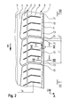
- the show FIGS. 1 and 2 only one of the two axially outer extension region of the tread profile, which from an axial position within the ground contact width T A in the region of the tire shoulder to outside the ground contact width T A and in the axial direction further extent axially outward to the off-shoulder area and at the tread profile adjoining tire side wall 9 extends.
- the tire side wall 9 extends in a known, but not shown here manner in the radial direction R inwardly to its fastening region, not shown, for fastening the tire on a tire rim.
- the attachment area is for example a known tire bead, which is equipped with a tensile bead core and is formed at the radially inner extension end of the tire sidewall 9.
- FIGS. 1 to 3 show the axially outer extension region of the tread pattern with a circumferentially extending over the entire circumference of the vehicle tire circumferential rib 1 and 1, arranged in the axial direction A outwardly, over the entire circumference of the vehicle pneumatic tire in the circumferential direction U aligned profile block row 2 and with a over the entire circumference of a pneumatic vehicle tire extended and aligned in the circumferential direction U profile block row 3, which is arranged axially adjacent to the profile block row 2.
- the Circumferential rib 1 and the profile block row 2 are separated from one another in the axial direction A by a circumferential groove 4 of known type, which is extended over the entire circumference of the pneumatic vehicle tire and is aligned in the circumferential direction U.
- the profile block row 2 and the profile block row 3 are in the axial direction A by a relative to the circumferential groove 4 narrower circumferential groove 5, which extends in a straight line over the entire circumference of the pneumatic vehicle tire in the circumferential direction U, separated from each other.
- the profile block row 2 and the profile block row 3 together form the shoulder region of the vehicle pneumatic tire and cover the not shown axial belt edges of the vehicle pneumatic tire in the radial direction R to the outside.
- the ground contact surface extends with its axial ground contact width T A into the axial extension region of the profile block row 3.
- the profile block row 2 is formed of a plurality of distributed over the circumference of the vehicle pneumatic tire and formed in the circumferential direction U in each case by a transverse groove 15 of spaced apart profile block elements 6 of known type.
- the profile block row 3 is formed from a plurality of distributed over the circumference of the vehicle pneumatic tire, arranged one behind the other in the circumferential direction U and each formed by a transverse groove 15 of spaced apart profile block elements 7 of known type.
- the profile block elements 6 extend in the axial direction from the circumferential groove 4 to the circumferential groove 5.
- the profile block elements 7 extend in the axial direction A from the circumferential groove 5 to an edge 10 delimiting the respective profile block element 7 in the axial direction A towards the tire sidewall 9
- the edge 10 extends in each case over the entire circumferential extent of a profile block element 7 from the one transverse to the profile block element 7 transverse groove 15 to the next profile block element 7 limiting transverse groove 15th
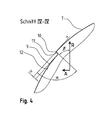
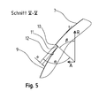
- the profile block elements 7 are formed in the plane surrounding the tire axis cutting planes on its radially outwardly bounding the profile block element 7 surface curved. As in the FIGS. 4 and 5 can be seen, lies the center of curvature of these curvatures in the Cutting planes, which includes the tire axis, respectively on the side of the surface facing the inside of the tire.
- the profile block elements 7 are limited on their facing away from the circumferential groove 5 axial outside each of a profile block element edge 11, which - as in the FIGS. 4 and 5 can be seen - straight over a height H, which forms the extension length between the edge 10 and formed in the surface of the tire sidewall 9 foot of the profile block element edge 11 extends.
- the profile block element flank 11 encloses an angle ⁇ to the tangent t formed in the edge 10 on the curved radially outer surface of the tread block element 7 and an angle of inclination ⁇ to the radial direction R of the pneumatic vehicle tire at 80 ° ⁇ in each sectional plane that includes the tire axis ⁇ ⁇ 100 ° and with 45 ° ⁇ ⁇ 60 °.
- the height H of the profile block element flank 11 is formed with 0.5 mm ⁇ H ⁇ 5 mm.
- ⁇ 90 °
- ⁇ 50 °
- H 1 mm
- the outer surface of the tire sidewall 9 delimiting the tire in the axial direction A extends inwardly in the radial direction R over the entire radial extent of the tire, initially radially outer extent of the tire sidewall substantially radially inward to its radially inner extent region and then on to the mounting portion of the tire formed on the radially inner extent of the sidewall and not shown.
- the figures show a further embodiment in which the edge 10 of a - in the in the FIGS. 1 to 3 with arrow entered - direction of rotation D of the pneumatic vehicle tire when driving forward of the vehicle tire mounted on a vehicle first longer circumferential extent 13 of measured in the circumferential direction U length L 1 and a downstream in the direction of rotation D significantly shorter Peripheral extension section 14, the measured in the circumferential direction U extension length L 2 is formed with L 1 > (5L 2 ).
- the edge 10 in the long extension section 13 is - as in FIG. 2 the edge 10, with the inclusion of an angle ⁇ with respect to the circumferential direction U, is aligned with 2 ° ⁇ ⁇ ⁇ 10 °, wherein in the direction of rotation D the cutting edge 10 in the extension region 13 forms an orientation with a smaller in the axial direction A inwardly towards the tire equatorial plane (not shown) Inclination.
- the cutting edge 10 is aligned with the direction of inclination of the cutting edge 13 opposite direction of inclination, so that the cutting edge 10 at the intersection of the extension regions 13 and 14 occupies their in the axial direction A of the vehicle pneumatic tire located furthest out position in the pneumatic vehicle tire.
- FIGS. 1 to 3 show a further embodiment in which in the tread block elements 6 and 7 additional sipes 8 are formed, which extends from the profile block element 6 on the circumferential groove 5 away, extend into the tread block element 7 and end at an axial distance from the edge 10.
- the sipes 8 are formed parallel to each other and to the transverse grooves 15 extending.
- the incisions 8 are formed as additional transverse grooves, which, however, also end at the axial distance from the edge 10 in the profile block element 7.
- the total extension length L (L 1 + L 2 ) of the edge 10 is selected to be 40 mm ⁇ L ⁇ 200 mm, and is selected depending on the tire dimension and the optimized pitch length variation of the tire.
Landscapes
- Engineering & Computer Science (AREA)
- Mechanical Engineering (AREA)
- Tires In General (AREA)
Abstract
Description
- Die Erfindung betrifft einen Fahrzeugluftreifen mit einem Laufstreifenprofil und mit zwei Reifenseitenwänden, bei dem das Laufstreifenprofil sich von Reifenschulter zu Reifenschulter über den gesamten axialen Erstreckungsbereich der Bodenaufstandsbreite TA erstreckt und bei dem in wenigstens einer Reifenschulter eine Profilblockreihe mit in Umfangsrichtung U des Fahrzeugluftreifens hintereinander angeordneten radial erhabenen Profilelementen und mit quer- oder schräg verlaufenden Rillen oder Nuten ausgebildet ist, wobei die Profilelemente außerhalb der Bodenaufstandsbreite TA in den Schnittebenen, die die Reifenachse beinhalten, an ihrer nach radial außen weisenden Oberfläche zur nächstliegenden Reifenseitenwand hin gekrümmt sind und sich die Reifenseitenwand mit ihrer nach axial außen weisenden Oberfläche in Verlängerung der Profilelemente an die Profilelemente anschließt und nach radial innen bis zu einem Befestigungsabschnitt des Reifens zur Befestigung auf einer Felge verlaufen.
- Bei derartigen Fahrzeugluftreifen ist im sogenannten Off-Shoulder-Bereich des Reifens, in welchem die Profilelemente in die Reifenseitenwand übergehen, die Reifenoberfläche mehr oder weniger glatt ausgebildet mit im Wesentlichen glattem fließendem Übergang. Zum Teil werden im Übergangsbereich - auch aus optischen Gründen - feinst ausgebildete Rillen ausgebildet, die den Übergang je nach Ausbildung hervorheben oder schwierige Materialübergänge kaschieren. Bei hohen Geschwindigkeiten fließt die anströmende Luft entlang der gekrümmten Oberfläche dieser im Off-Shoulder-Bereich gekrümmten Profilelemente und der Seitenwand. Die glatten Oberflächen in diesem im Bereich der Krümmung ausgebildeten Übergang bewirken undefiniert Verwirbelungen und Ablösungen der Grenzschicht, die mit Widerstandserhöhungen einhergehen. Die optisch bedingten Feinstrillen können zusätzliche Störungen der Grenzschicht einhergehend mit weiteren Verwirbelungen und Grenzschichtablösungen bewirken, wodurch der Luftwiderstand weiter erhöht wird. Diese Effekte bewirken eine Erhöhung des Gesamt-Energieverbrauchs des Fahrzeugluftreifens und können darüber hinaus zu unerwünschter Geräuschentstehung des Fahrzeugs beitragen. Gerade bei hohen Anströmungsgeschwindigkeiten, wie sie bei PKW-Fahrzeugen erreicht werden können, besteht verstärkt die Gefahr des Auftretens derartiger Effekte.
- Der Erfindung liegt die Aufgabe zugrunde, mit einfachen Mitteln einen derartigen Fahrzeugluftreifen mit reduziertem Luftwiderstand zu ermöglichen.
- Die Aufgabe wird erfindungsgemäß durch die Ausbildung eines Fahrzeugluftreifen mit einem Laufstreifenprofil und mit zwei Reifenseitenwänden, bei dem das Laufstreifenprofil sich von Reifenschulter zu Reifenschulter über den gesamten axialen Erstreckungsbereich der Bodenaufstandsbreite TA erstreckt und bei dem in wenigstens einer Reifenschulter eine Profilblockreihe mit in Umfangsrichtung U des Fahrzeugluftreifens hintereinander angeordneten radial erhabenen Profilelementen und mit quer- oder schräg verlaufenden Rillen oder Nuten ausgebildet ist, wobei die Profilelemente außerhalb der Bodenaufstandsbreite TA in den Schnittebenen, die die Reifenachse beinhalten, an ihrer nach radial außen weisenden Oberfläche zur nächst liegenden Reifenseitenwand gekrümmt ist und sich die Reifenseitenwand mit ihrer nach axial außen weisenden Oberfläche in Verlängerung der Profilelemente an die Profilelemente anschließt und nach radial innen bis zu einem Befestigungsabschnitt des Reifens zur Befestigung auf einer Felge verlaufen, gelöst, bei dem sich die Profilelemente mit ihrer radial äußeren gekrümmten Oberfläche in axialer Richtung A in Richtung zur Reifenseitenwand bis zu einer in Umfangsrichtung U des Fahrzeugluftreifens erstreckte Kante erstrecken und bei dem die Profilelemente an der Kante von einer Flanke begrenzt werden, welche jeweils in den Schnittebenen, die die Reifenachse beinhalten, unter einem Neigungswinkel α zur Tangente t mit 80° ≤ α ≤ 100° an die gekrümmte radial äußere Oberfläche des Profilelementes in der Kante und mit einem Neigungswinkel β zur Radialen R des Fahrzeugluftreifens mit 45°< β ≤ 60° verlaufend ausgebildet ist und die sich bis zur radial äußeren Oberfläche der Reifenseitenwand erstreckt, und bei dem sich die radial äußere Oberfläche der Reifenseitenwand von der Flanke ausgehend dach radial innen bis zu dem Befestigungsabschnitt des Reifens erstreckt.
- Durch diese Ausbildung erhält die Oberfläche des Reifens im kritischen Bereich der Off-Shoulder im Anschluss an die Krümmung des Profilelementes im Übergang zwischen Profilelement und Reifenseitenwand durch die Flanke mit Neigungswinkel α und β eine gezielte Abrisskante, welche einen definierten Abriss der Grenzschicht in dem für Turbulenzen kritischen Bereich ermöglicht. Die Entstehung ungewünschter Verwirbelungen der Strömung und unkontrollierter Abrisse der Strömung kann hierdurch reduziert werden. Der Luftwiderstand des Reifens beim Fahren kann hierdurch reduziert und durch undefinierte Verwirbelungs- und Ablöseerscheinungen bedingte Geräuschentstehung verringert werden.
- Besonders vorteilhaft zur einfachen Schaffung einer sicheren Abrisskante ist die Ausbildung eines Fahrzeugluftreifens gemäß den Merkmalen von Anspruch 2, wobei α =90° ausgebildet ist.
- Besonders vorteilhaft ist die Ausbildung eines Fahrzeugluftreifens gemäß den Merkmalen von Anspruch 3, wobei β=50° ausgebildet ist.
- Besonders vorteilhaft ist die Ausbildung eines Fahrzeugluftreifens gemäß den Merkmalen von Anspruch 4, wobei die Kante zumindest in ihrem Hauptstreckungsabschnitt in Umfangsrichtung U in ihrem Verlauf jeweils einen Winkel γ zur Umfangsrichtung U einschließt mit 2°≤ γ ≤10° - insbesondere mit γ = 5°. Dies ermöglicht beim drehenden Reifen eine gleitend auf die anströmende Luft einwirkende Abrisskante.
- Die Erfindung wird im Folgenden an Hand eines in den
Figuren 1 bis 5 dargestellten Ausführungsbeispieles eines Fahrzeugluftreifens für Personenkraftwagen (PKW) näher erläutert. Hierin zeigen - Fig. 1
- Umfangsabschnitt eines Fahrzeugluftreifens in perspektivischer Darstellung mit Blick auf das Laufstreifenprofil im Bereich der rechten Reifenschulter,
- Fig. 2
- Fahrzeugluftreifen gemäß
Figur 1 in Draufsicht, - Fig. 3
- Darstellung des Fahrzeugluftreifens von
Figur 1 in Seitenansicht gemäß Ansicht III-III vonFigur 2 zur Darstellung des radial äußeren Erstreckungsbereiches des Reifens, - Fig. 4
- Querschnittsdarstellung des Übergangsbereichs von Laufstreifen zur Reifenseitenwand gemäß Schnitt IV-IV von
Figur 2 und - Fig. 5
- Querschnittsdarstellung des Übergangsbereichs von Laufstreifen zur Reifenseitenwand gemäß Schnitt V-V von
Figur 2 . - Die Figuren zeigen einen Fahrzeugluftreifen für PKW-Reifen, der für Hochgeschwindigkeiten geeignet ist. Zur Vereinfachung zeigen die
Figuren 1 und2 lediglich einen der beiden axial äußeren Erstreckungsbereich des Laufstreifensprofiles, welches von einer axialen Position innerhalb der Bodenaufstandsbreite TA im Bereich der Reifenschulter bis außerhalb der Bodenaufstandsbreite TA und im weiteren axialen Erstreckungsbereich nach axial außen bis in den Off-Shoulder-Bereich und die sich an das Laufstreifenprofil anschließende Reifenseitenwand 9 erstreckt. Die Reifenseitenwand 9erstreckt sich in bekannter, jedoch hier nicht näher dargestellten Weise in radialer Richtung R nach innen bis zu ihrem nicht dargestellten Befestigungsbereich zur Befestigung des Reifens auf einer Reifenfelge. Der Befestigungsbereich ist beispielsweise ein bekannter Reifenwulst, der mit einem zugfesten Wulstkern bestückt und am radial inneren Erstreckungsende der Reifenseitenwand 9 ausgebildet ist. - Die
Figuren 1 bis 3 zeigen den axial äußeren Erstreckungsbereich des Laufstreifenprofils mit einer über den gesamten Umfang des Fahrzeugluftreifens erstreckten und in Umfangsrichtung U ausgerichteten Umfangsrippe 1, mit einer in axialer Richtung A nach außen benachbart angeordneten, über den gesamten Umfang des Fahrzeugluftreifens in Umfangsrichtung U ausgerichteten Profilblockreihe 2 und mit einer über den gesamten Umfang eines Fahrzeugluftreifens erstreckten und in Umfangsrichtung U ausgerichteten Profilblockreihe 3, welche axial neben der Profilblockreihe 2 angeordnet ist. Die Umfangsrippe 1 und die Profilblockreihe 2 sind in axialer Richtung A durch eine über den gesamten Umfang des Fahrzeugluftreifens erstreckte und in Umfangsrichtung U ausgerichtete Umfangsrille 4 bekannter Art voneinander getrennt. Die Profilblockreihe 2 und die Profilblockreihe 3 sind in axialer Richtung A durch eine gegenüber der Umfangsrille 4 schmalere Umfangsrille 5, welche sich über den gesamten Umfang des Fahrzeugluftreifens in Umfangsrichtung U ausgerichtet geradlinig erstreckt, voneinander getrennt. Die Profilblockreihe 2 und die Profilblockreihe 3 bilden gemeinsam den Schulterbereich des Fahrzeugluftreifens und decken die nicht dargestellten axialen Gürtelkanten des Fahrzeugluftreifens in radialer Richtung R nach außen ab. - Die Bodenaufstandsfläche erstreckt sich mit ihrer axialen Bodenaufstandsbreite TA bis in den axialen Erstreckungsbereich der Profilblockreihe 3 hinein. Die Profilblockreihe 2 ist aus einer Vielzahl von über den Umfang des Fahrzeugluftreifens verteilt angeordneten und in Umfangsrichtung U jeweils durch eine Querrille 15 von einander beabstandeten Profilblockelementen 6 bekannter Art ausgebildet. Die Profilblockreihe 3 ist aus einer Vielzahl von über den Umfang des Fahrzeugluftreifens verteilten, in Umfangsrichtung U hintereinander angeordneten und jeweils durch eine Querrille 15 von einander beabstandeten Profilblockelementen 7 bekannter Art ausgebildet. Die Profilblockelemente 6 erstrecken sich in axialer Richtung von der Umfangsrille 4 bis zur Umfangsrille 5. Die Profilblockelemente 7 erstrecken sich in axialer Richtung A von der Umfangsrille 5 bis zu einer das jeweilige Profilblockelement 7 in axialer Richtung A nach außen zur Reifenseitenwand 9 hin begrenzenden Kante 10. Die Kante 10 erstreckt sich jeweils über die gesamte Umfangserstreckung eines Profilblockelementes 7 von der einen das Profilblockelement 7 begrenzenden Querrille 15 bis zur nächsten das Profilblockelement 7 begrenzenden Querrille 15.
- Wie in den
Figuren 1 bis 5 zu erkennen ist, sind die Profilblockelemente 7 in den die Reifenachse beinhaltenden Schnittebenen an ihrer nach radial außen das Profilblockelement 7 begrenzenden Oberfläche gekrümmt ausgebildet. Wie in denFiguren 4 und5 zu erkennen ist, liegt der Krümmungsmittelpunkt dieser Krümmungen in den Schnittebenen, welche die Reifenachse beinhaltet, jeweils auf der zur Innenseite des Reifens weisenden Seite der Oberfläche. - Wie in den
Figuren 4 und5 zu erkennen ist, sind die Profilblockelemente 7 auf ihrer von der Umfangsrille 5 weg weisenden axialen Außenseite jeweils von einer Profilblockelementflanke 11 begrenzt, die sich - wie in denFiguren 4 und5 zu erkennen ist - geradlinig über eine Höhe H, die die Erstreckungslänge zwischen der Kante 10 und dem in der Oberfläche der Reifenseitenwand 9 ausgebildeten Fuß der Profilblockelementflanke 11 bildet, erstreckt. Die Profilblockelementflanke 11 schließt dabei in jeder Schnittebene, die die Reifenachse beinhaltet, einen Winkel α zu der in der Kante 10 an die gekrümmte radial äußere Oberfläche des Profilblockelementes 7 gebildeten Tangente t und einen Neigungswinkel β zur radialen Richtung R des Fahrzeugluftreifens ein mit 80° ≤ α ≤ 100° und mit 45° < β ≤ 60°. - Die Höhe H der Profilblockelementflanke 11 ist mit 0,5 mm ≤ H ≤,5 mm ausgebildet.
- Im dargestellten Ausführungsbeispiel ist α = 90°, β = 50° und H = 1 mm ausgebildet.
- Von dem den Schnittpunkt zwischen Reifenseitenwand 9 und Profilblockelementflanke 11 gebildet Fuß der Flanke 11 ausgehend erstreckt sich die äußere den Reifen in axialer Richtung A begrenzende Oberfläche der Reifenseitenwand 9 über den gesamten radialen Erstreckungsbereich des Reifens in radialer Richtung R nach innen und zwar zunächst mit ihrem radial äußeren Erstreckungsbereich der Reifenseitenwand im Wesentlichen nach radial innen bis zu ihrem radial inneren Erstreckungsbereich und dann weiter bis zu dem am radial inneren Erstreckungsbereich der Seitenwand ausgebildeten und nicht dargestellten Befestigungsbereich des Reifens.
- Die Figuren zeigen ein weiteres Ausführungsbeispiel, bei der die Kante 10 aus einem - in der in den
Figuren 1 bis 3 mit Pfeil eingetragenen - Drehrichtung D des Fahrzeugluftreifens bei Vorwärtsfahrt des auf ein Fahrzeug montierten Fahrzeugluftreifens ersten längeren Umfangserstreckungsbereich 13 der in Umfangsrichtung U gemessenen Länge L1 und aus einem in Drehrichtung D nachgeordneten deutlichen kürzeren Umfangserstreckungsabschnitt 14, der in Umfangsrichtung U gemessenen Erstreckungslänge L2 ausgebildet ist mit L1>(5L2). - Im langen Erstreckungsabschnitt 13 ist - wie in
Figur 2 dargestellt ist - die Kante 10 unter Einschluss eines Winkels γ zur Umfangsrichtung U mit 2° ≤ γ ≤ 10° ausgerichtet, wobei in Drehrichtung D die Schnittkante 10 im Erstreckungsbereich 13 eine Orientierung mit geringer in axialer Richtung A nach innen zur nicht dargestellten Reifenäquatorebene hin ausgebildeten Neigung aufweist. In dem kurzen Erstreckungsabschnitt 14 ist die Schnittkante 10 mit zur Neigungsrichtung der Schnittkante 13 gegenläufiger Neigungsrichtung ausgerichtet, so dass die Schnittkante 10 im Schnittpunkt der Erstreckungsbereiche 13 und 14 ihre in axialer Richtung A des Fahrzeugluftreifens am weitest außen gelegene Position im Fahrzeugluftreifen einnimmt. - Die
Figuren 1 bis 3 zeigen ein weiteres Ausführungsbeispiel, bei dem in den Profilblockelementen 6 und 7 zusätzliche Feineinschnitte 8 ausgebildet sind, die sich ausgehend vom Profilblockelement 6 über die Umfangsrille 5 hinweg verlängert, bis in das Profilblockelement 7 hinein erstrecken und mit axialem Abstand zur Kante 10 enden. - Die Feineinschnitte 8 sind parallel zueinander und zu den Querrillen 15 verlaufend ausgebildet.
- In einem anderen Ausführungsbeispiel sind die Einschnitte 8 als zusätzliche Quernuten ausgebildet, die jedoch ebenfalls im axialen Abstand von der Kante 10 im Profilblockelement 7 enden.
- Die Gesamterstreckungslänge L = (L1 + L2) der Kante 10 ist mit 40 mm ≤ L ≤ 200 mm gewählt und ist in Abhängigkeit von der Reifendimension und der optimierten Pitchlängen-Variation des Reifens gewählt.
-
- 1
- Umfangsrippe
- 2
- Profilblockreihe
- 3
- Profilblockreihe
- 4
- Umfangsrille
- 5
- Umfangsrille
- 6
- Profilblockelement
- 7
- Profilblockelement
- 8
- Feineinschnitt
- 9
- Reifenseitenwand
- 10
- Kante
- 11
- Flanke
- 12
- Optische Rille
- 13
- Kantenerstreckungsabschnitt
- 14
- Kantenerstreckungsabschnitt
- 15
- Querrille
Claims (4)
- Fahrzeugluftreifen mit einem Laufstreifenprofil und mit zwei Reifenseitenwänden (9), bei dem das Laufstreifenprofil sich von Reifenschulter zu Reifenschulter über den gesamten axialen Erstreckungsbereich der Bodenaufstandsbreite TA erstreckt und bei dem in wenigstens einer Reifenschulter eine Profilblockreihe (3) mit in Umfangsrichtung U des Fahrzeugluftreifens hintereinander angeordneten radial erhabenen Profilelementen (7) und mit quer- oder schräg verlaufenden Rillen (15) oder Nuten ausgebildet ist, wobei die Profilelemente (7) außerhalb der Bodenaufstandsbreite TA in den Schnittebenen, die die Reifenachse beinhalten, an ihrer nach radial außen weisenden Oberfläche zur nächstliegenden Reifenseitenwand (9) hin gekrümmt sind und sich die Reifenseitenwand (9) mit ihrer nach axial außen weisenden Oberfläche in Verlängerung der Profilelemente (7) an die Profilelemente (7) anschließt und nach radial innen bis zu einem Befestigungsabschnitt des Reifens zur Befestigung auf einer Felge verlaufen, dadurch gekennzeichnet,
dass sich die Profilelemente (7) mit ihrer radial äußeren gekrümmten Oberfläche in axialer Richtung A in Richtung zur Reifenseitenwand (9) bis zu einer in Umfangsrichtung U des Fahrzeugluftreifens erstreckte Kante (10) erstrecken und dass die Profilelemente (7) an der Kante (10) von einer Flanke (11) begrenzt werden, welche jeweils in den Schnittebenen, die die Reifenachse beinhalten, unter einem Neigungswinkel α zur Tangente t mit 80° ≤ α ≤100° an die gekrümmte radial äußere Oberfläche des Profilelementes (7) in der Kante (10) und mit einem Neigungswinkel β zur Radialen R des Fahrzeugluftreifens mit 45°< β ≤ 60° verlaufend ausgebildet ist und sich bis zur radial äußeren Oberfläche der Reifenseitenwand (9) erstreckt, und
dass sich die radial äußere Oberfläche der Reifenseitenwand (9) von der Flanke (11) ausgehend nach radial innen bis zu dem Befestigungsabschnitt des Reifens erstreckt. - Fahrzeugluftreifen gemäß den Merkmalen von Anspruch 1,
wobei α =90° ausgebildet ist. - Fahrzeugluftreifen gemäß den Merkmalen von Anspruch 1 oder Anspruch 2, wobei β=50° ausgebildet ist.
- Fahrzeugluftreifen gemäß den Merkmalen von einem oder mehreren der vorangegangenen Ansprüche,
wobei die Kante (10) zumindest in ihrem Hauptstreckungsabschnitt (13) in Umfangsrichtung U in ihrem Verlauf jeweils einen Winkel γ zur Umfangsrichtung U einschließt mit 2°≤ γ ≤10° - insbesondere mit γ = 5°.
Priority Applications (1)
| Application Number | Priority Date | Filing Date | Title |
|---|---|---|---|
| PL10181685T PL2332748T3 (pl) | 2009-12-03 | 2010-09-29 | Opona samochodowa |
Applications Claiming Priority (1)
| Application Number | Priority Date | Filing Date | Title |
|---|---|---|---|
| DE102009044750A DE102009044750A1 (de) | 2009-12-03 | 2009-12-03 | Fahrzeugluftreifen |
Publications (2)
| Publication Number | Publication Date |
|---|---|
| EP2332748A1 true EP2332748A1 (de) | 2011-06-15 |
| EP2332748B1 EP2332748B1 (de) | 2016-02-10 |
Family
ID=43709191
Family Applications (1)
| Application Number | Title | Priority Date | Filing Date |
|---|---|---|---|
| EP10181685.8A Active EP2332748B1 (de) | 2009-12-03 | 2010-09-29 | Fahrzeugluftreifen |
Country Status (3)
| Country | Link |
|---|---|
| EP (1) | EP2332748B1 (de) |
| DE (1) | DE102009044750A1 (de) |
| PL (1) | PL2332748T3 (de) |
Cited By (2)
| Publication number | Priority date | Publication date | Assignee | Title |
|---|---|---|---|---|
| EP2404768A3 (de) * | 2010-07-05 | 2013-10-23 | Continental Reifen Deutschland GmbH | Fahrzeugluftreifen |
| EP3750723A1 (de) * | 2019-06-13 | 2020-12-16 | Continental Reifen Deutschland GmbH | Fahrzeugluftreifen |
Citations (1)
| Publication number | Priority date | Publication date | Assignee | Title |
|---|---|---|---|---|
| EP2204295A1 (de) * | 2007-09-13 | 2010-07-07 | Sumitomo Rubber Industries, Ltd. | Geländeluftreifen |
-
2009
- 2009-12-03 DE DE102009044750A patent/DE102009044750A1/de not_active Withdrawn
-
2010
- 2010-09-29 EP EP10181685.8A patent/EP2332748B1/de active Active
- 2010-09-29 PL PL10181685T patent/PL2332748T3/pl unknown
Patent Citations (1)
| Publication number | Priority date | Publication date | Assignee | Title |
|---|---|---|---|---|
| EP2204295A1 (de) * | 2007-09-13 | 2010-07-07 | Sumitomo Rubber Industries, Ltd. | Geländeluftreifen |
Cited By (2)
| Publication number | Priority date | Publication date | Assignee | Title |
|---|---|---|---|---|
| EP2404768A3 (de) * | 2010-07-05 | 2013-10-23 | Continental Reifen Deutschland GmbH | Fahrzeugluftreifen |
| EP3750723A1 (de) * | 2019-06-13 | 2020-12-16 | Continental Reifen Deutschland GmbH | Fahrzeugluftreifen |
Also Published As
| Publication number | Publication date |
|---|---|
| PL2332748T3 (pl) | 2016-07-29 |
| EP2332748B1 (de) | 2016-02-10 |
| DE102009044750A1 (de) | 2011-06-09 |
Similar Documents
| Publication | Publication Date | Title |
|---|---|---|
| EP2892736B1 (de) | Fahrzeugluftreifen | |
| EP3589500B1 (de) | Fahrzeugluftreifen | |
| EP3388256B1 (de) | Fahrzeugluftreifen | |
| DE69606618T2 (de) | Luftreifen | |
| DE102012105120B4 (de) | Laufstreifenprofil eines Fahrzeugreifens | |
| EP3785938A1 (de) | Fahrzeugluftreifen | |
| EP2714434B1 (de) | Laufstreifenprofil eines fahrzeugluftreifens für nutzfahrzeuge | |
| EP2119574B1 (de) | Laufflächenprofil eines Fahrzeugreifens | |
| EP4514627B1 (de) | Fahrzeugreifen | |
| WO2007028442A9 (de) | Laufflächenprofil mit asymmetrischen umfangsnuten | |
| EP2332748B1 (de) | Fahrzeugluftreifen | |
| EP3224060B1 (de) | Fahrzeugluftreifen | |
| DE69711248T2 (de) | Lauffläche für luftreifen | |
| EP2512828B1 (de) | Fahrzeugluftreifen | |
| EP2914448B1 (de) | Fahrzeugluftreifen | |
| EP1506884B1 (de) | Laufflächenprofil eines Fahrzeugluftreifens | |
| EP4512638B1 (de) | Laufstreifen für einen fahrzeugreifen und fahrzeugreifen | |
| EP2412548B1 (de) | Fahrzeugluftreifen | |
| EP4147885B1 (de) | Fahrzeugreifen | |
| EP3112188B1 (de) | Fahrzeugluftreifen | |
| EP4434773B1 (de) | Fahrzeugluftreifen | |
| EP2895339B1 (de) | Fahrzeugluftreifen | |
| EP4065390B1 (de) | Fahrzeugluftreifen | |
| EP2329966B1 (de) | Laufflächenprofil eines Fahrzeugreifens | |
| EP3564046B1 (de) | Fahrzeugluftreifen |
Legal Events
| Date | Code | Title | Description |
|---|---|---|---|
| PUAI | Public reference made under article 153(3) epc to a published international application that has entered the european phase |
Free format text: ORIGINAL CODE: 0009012 |
|
| AK | Designated contracting states |
Kind code of ref document: A1 Designated state(s): AL AT BE BG CH CY CZ DE DK EE ES FI FR GB GR HR HU IE IS IT LI LT LU LV MC MK MT NL NO PL PT RO SE SI SK SM TR |
|
| AX | Request for extension of the european patent |
Extension state: BA ME RS |
|
| 17P | Request for examination filed |
Effective date: 20111215 |
|
| 17Q | First examination report despatched |
Effective date: 20120420 |
|
| REG | Reference to a national code |
Ref country code: DE Ref legal event code: R079 Ref document number: 502010011036 Country of ref document: DE Free format text: PREVIOUS MAIN CLASS: B60C0011240000 Ipc: B60C0011010000 |
|
| RIC1 | Information provided on ipc code assigned before grant |
Ipc: B60C 11/03 20060101ALI20150423BHEP Ipc: B60C 13/02 20060101ALI20150423BHEP Ipc: B60C 11/01 20060101AFI20150423BHEP |
|
| GRAP | Despatch of communication of intention to grant a patent |
Free format text: ORIGINAL CODE: EPIDOSNIGR1 |
|
| INTG | Intention to grant announced |
Effective date: 20150908 |
|
| GRAS | Grant fee paid |
Free format text: ORIGINAL CODE: EPIDOSNIGR3 |
|
| GRAA | (expected) grant |
Free format text: ORIGINAL CODE: 0009210 |
|
| AK | Designated contracting states |
Kind code of ref document: B1 Designated state(s): AL AT BE BG CH CY CZ DE DK EE ES FI FR GB GR HR HU IE IS IT LI LT LU LV MC MK MT NL NO PL PT RO SE SI SK SM TR |
|
| REG | Reference to a national code |
Ref country code: GB Ref legal event code: FG4D Free format text: NOT ENGLISH |
|
| REG | Reference to a national code |
Ref country code: AT Ref legal event code: REF Ref document number: 774459 Country of ref document: AT Kind code of ref document: T Effective date: 20160215 Ref country code: CH Ref legal event code: EP |
|
| REG | Reference to a national code |
Ref country code: IE Ref legal event code: FG4D Free format text: LANGUAGE OF EP DOCUMENT: GERMAN |
|
| REG | Reference to a national code |
Ref country code: DE Ref legal event code: R096 Ref document number: 502010011036 Country of ref document: DE |
|
| REG | Reference to a national code |
Ref country code: LT Ref legal event code: MG4D |
|
| REG | Reference to a national code |
Ref country code: NL Ref legal event code: MP Effective date: 20160210 |
|
| PG25 | Lapsed in a contracting state [announced via postgrant information from national office to epo] |
Ref country code: HR Free format text: LAPSE BECAUSE OF FAILURE TO SUBMIT A TRANSLATION OF THE DESCRIPTION OR TO PAY THE FEE WITHIN THE PRESCRIBED TIME-LIMIT Effective date: 20160210 Ref country code: NO Free format text: LAPSE BECAUSE OF FAILURE TO SUBMIT A TRANSLATION OF THE DESCRIPTION OR TO PAY THE FEE WITHIN THE PRESCRIBED TIME-LIMIT Effective date: 20160510 Ref country code: GR Free format text: LAPSE BECAUSE OF FAILURE TO SUBMIT A TRANSLATION OF THE DESCRIPTION OR TO PAY THE FEE WITHIN THE PRESCRIBED TIME-LIMIT Effective date: 20160511 Ref country code: ES Free format text: LAPSE BECAUSE OF FAILURE TO SUBMIT A TRANSLATION OF THE DESCRIPTION OR TO PAY THE FEE WITHIN THE PRESCRIBED TIME-LIMIT Effective date: 20160210 Ref country code: FI Free format text: LAPSE BECAUSE OF FAILURE TO SUBMIT A TRANSLATION OF THE DESCRIPTION OR TO PAY THE FEE WITHIN THE PRESCRIBED TIME-LIMIT Effective date: 20160210 |
|
| PG25 | Lapsed in a contracting state [announced via postgrant information from national office to epo] |
Ref country code: LT Free format text: LAPSE BECAUSE OF FAILURE TO SUBMIT A TRANSLATION OF THE DESCRIPTION OR TO PAY THE FEE WITHIN THE PRESCRIBED TIME-LIMIT Effective date: 20160210 Ref country code: IS Free format text: LAPSE BECAUSE OF FAILURE TO SUBMIT A TRANSLATION OF THE DESCRIPTION OR TO PAY THE FEE WITHIN THE PRESCRIBED TIME-LIMIT Effective date: 20160610 Ref country code: NL Free format text: LAPSE BECAUSE OF FAILURE TO SUBMIT A TRANSLATION OF THE DESCRIPTION OR TO PAY THE FEE WITHIN THE PRESCRIBED TIME-LIMIT Effective date: 20160210 Ref country code: LV Free format text: LAPSE BECAUSE OF FAILURE TO SUBMIT A TRANSLATION OF THE DESCRIPTION OR TO PAY THE FEE WITHIN THE PRESCRIBED TIME-LIMIT Effective date: 20160210 Ref country code: SE Free format text: LAPSE BECAUSE OF FAILURE TO SUBMIT A TRANSLATION OF THE DESCRIPTION OR TO PAY THE FEE WITHIN THE PRESCRIBED TIME-LIMIT Effective date: 20160210 Ref country code: PT Free format text: LAPSE BECAUSE OF FAILURE TO SUBMIT A TRANSLATION OF THE DESCRIPTION OR TO PAY THE FEE WITHIN THE PRESCRIBED TIME-LIMIT Effective date: 20160613 |
|
| REG | Reference to a national code |
Ref country code: FR Ref legal event code: PLFP Year of fee payment: 7 |
|
| PG25 | Lapsed in a contracting state [announced via postgrant information from national office to epo] |
Ref country code: DK Free format text: LAPSE BECAUSE OF FAILURE TO SUBMIT A TRANSLATION OF THE DESCRIPTION OR TO PAY THE FEE WITHIN THE PRESCRIBED TIME-LIMIT Effective date: 20160210 Ref country code: EE Free format text: LAPSE BECAUSE OF FAILURE TO SUBMIT A TRANSLATION OF THE DESCRIPTION OR TO PAY THE FEE WITHIN THE PRESCRIBED TIME-LIMIT Effective date: 20160210 |
|
| REG | Reference to a national code |
Ref country code: DE Ref legal event code: R097 Ref document number: 502010011036 Country of ref document: DE |
|
| PG25 | Lapsed in a contracting state [announced via postgrant information from national office to epo] |
Ref country code: SM Free format text: LAPSE BECAUSE OF FAILURE TO SUBMIT A TRANSLATION OF THE DESCRIPTION OR TO PAY THE FEE WITHIN THE PRESCRIBED TIME-LIMIT Effective date: 20160210 Ref country code: RO Free format text: LAPSE BECAUSE OF FAILURE TO SUBMIT A TRANSLATION OF THE DESCRIPTION OR TO PAY THE FEE WITHIN THE PRESCRIBED TIME-LIMIT Effective date: 20160210 Ref country code: SK Free format text: LAPSE BECAUSE OF FAILURE TO SUBMIT A TRANSLATION OF THE DESCRIPTION OR TO PAY THE FEE WITHIN THE PRESCRIBED TIME-LIMIT Effective date: 20160210 Ref country code: CZ Free format text: LAPSE BECAUSE OF FAILURE TO SUBMIT A TRANSLATION OF THE DESCRIPTION OR TO PAY THE FEE WITHIN THE PRESCRIBED TIME-LIMIT Effective date: 20160210 |
|
| PLBE | No opposition filed within time limit |
Free format text: ORIGINAL CODE: 0009261 |
|
| STAA | Information on the status of an ep patent application or granted ep patent |
Free format text: STATUS: NO OPPOSITION FILED WITHIN TIME LIMIT |
|
| 26N | No opposition filed |
Effective date: 20161111 |
|
| PG25 | Lapsed in a contracting state [announced via postgrant information from national office to epo] |
Ref country code: SI Free format text: LAPSE BECAUSE OF FAILURE TO SUBMIT A TRANSLATION OF THE DESCRIPTION OR TO PAY THE FEE WITHIN THE PRESCRIBED TIME-LIMIT Effective date: 20160210 Ref country code: BE Free format text: LAPSE BECAUSE OF NON-PAYMENT OF DUE FEES Effective date: 20160930 Ref country code: BG Free format text: LAPSE BECAUSE OF FAILURE TO SUBMIT A TRANSLATION OF THE DESCRIPTION OR TO PAY THE FEE WITHIN THE PRESCRIBED TIME-LIMIT Effective date: 20160510 |
|
| PG25 | Lapsed in a contracting state [announced via postgrant information from national office to epo] |
Ref country code: MC Free format text: LAPSE BECAUSE OF FAILURE TO SUBMIT A TRANSLATION OF THE DESCRIPTION OR TO PAY THE FEE WITHIN THE PRESCRIBED TIME-LIMIT Effective date: 20160210 |
|
| REG | Reference to a national code |
Ref country code: CH Ref legal event code: PL |
|
| REG | Reference to a national code |
Ref country code: IE Ref legal event code: MM4A |
|
| PG25 | Lapsed in a contracting state [announced via postgrant information from national office to epo] |
Ref country code: CH Free format text: LAPSE BECAUSE OF NON-PAYMENT OF DUE FEES Effective date: 20160930 Ref country code: LI Free format text: LAPSE BECAUSE OF NON-PAYMENT OF DUE FEES Effective date: 20160930 Ref country code: IE Free format text: LAPSE BECAUSE OF NON-PAYMENT OF DUE FEES Effective date: 20160929 |
|
| PG25 | Lapsed in a contracting state [announced via postgrant information from national office to epo] |
Ref country code: LU Free format text: LAPSE BECAUSE OF NON-PAYMENT OF DUE FEES Effective date: 20160929 |
|
| REG | Reference to a national code |
Ref country code: FR Ref legal event code: PLFP Year of fee payment: 8 |
|
| REG | Reference to a national code |
Ref country code: AT Ref legal event code: MM01 Ref document number: 774459 Country of ref document: AT Kind code of ref document: T Effective date: 20160929 |
|
| REG | Reference to a national code |
Ref country code: BE Ref legal event code: MM Effective date: 20160930 |
|
| PG25 | Lapsed in a contracting state [announced via postgrant information from national office to epo] |
Ref country code: AT Free format text: LAPSE BECAUSE OF NON-PAYMENT OF DUE FEES Effective date: 20160929 |
|
| PG25 | Lapsed in a contracting state [announced via postgrant information from national office to epo] |
Ref country code: CY Free format text: LAPSE BECAUSE OF FAILURE TO SUBMIT A TRANSLATION OF THE DESCRIPTION OR TO PAY THE FEE WITHIN THE PRESCRIBED TIME-LIMIT Effective date: 20160210 Ref country code: HU Free format text: LAPSE BECAUSE OF FAILURE TO SUBMIT A TRANSLATION OF THE DESCRIPTION OR TO PAY THE FEE WITHIN THE PRESCRIBED TIME-LIMIT; INVALID AB INITIO Effective date: 20100929 |
|
| PG25 | Lapsed in a contracting state [announced via postgrant information from national office to epo] |
Ref country code: MK Free format text: LAPSE BECAUSE OF FAILURE TO SUBMIT A TRANSLATION OF THE DESCRIPTION OR TO PAY THE FEE WITHIN THE PRESCRIBED TIME-LIMIT Effective date: 20160210 Ref country code: MT Free format text: LAPSE BECAUSE OF FAILURE TO SUBMIT A TRANSLATION OF THE DESCRIPTION OR TO PAY THE FEE WITHIN THE PRESCRIBED TIME-LIMIT Effective date: 20160210 Ref country code: TR Free format text: LAPSE BECAUSE OF FAILURE TO SUBMIT A TRANSLATION OF THE DESCRIPTION OR TO PAY THE FEE WITHIN THE PRESCRIBED TIME-LIMIT Effective date: 20160210 |
|
| REG | Reference to a national code |
Ref country code: FR Ref legal event code: PLFP Year of fee payment: 9 |
|
| PG25 | Lapsed in a contracting state [announced via postgrant information from national office to epo] |
Ref country code: AL Free format text: LAPSE BECAUSE OF FAILURE TO SUBMIT A TRANSLATION OF THE DESCRIPTION OR TO PAY THE FEE WITHIN THE PRESCRIBED TIME-LIMIT Effective date: 20160210 |
|
| PGFP | Annual fee paid to national office [announced via postgrant information from national office to epo] |
Ref country code: FR Payment date: 20180925 Year of fee payment: 9 Ref country code: IT Payment date: 20180925 Year of fee payment: 9 |
|
| PGFP | Annual fee paid to national office [announced via postgrant information from national office to epo] |
Ref country code: GB Payment date: 20180919 Year of fee payment: 9 Ref country code: PL Payment date: 20180917 Year of fee payment: 9 |
|
| PG25 | Lapsed in a contracting state [announced via postgrant information from national office to epo] |
Ref country code: IT Free format text: LAPSE BECAUSE OF NON-PAYMENT OF DUE FEES Effective date: 20190929 |
|
| GBPC | Gb: european patent ceased through non-payment of renewal fee |
Effective date: 20190929 |
|
| PG25 | Lapsed in a contracting state [announced via postgrant information from national office to epo] |
Ref country code: FR Free format text: LAPSE BECAUSE OF NON-PAYMENT OF DUE FEES Effective date: 20190930 Ref country code: GB Free format text: LAPSE BECAUSE OF NON-PAYMENT OF DUE FEES Effective date: 20190929 |
|
| PG25 | Lapsed in a contracting state [announced via postgrant information from national office to epo] |
Ref country code: PL Free format text: LAPSE BECAUSE OF NON-PAYMENT OF DUE FEES Effective date: 20190929 |
|
| REG | Reference to a national code |
Ref country code: DE Ref legal event code: R081 Ref document number: 502010011036 Country of ref document: DE Owner name: CONTINENTAL REIFEN DEUTSCHLAND GMBH, DE Free format text: FORMER OWNER: CONTINENTAL REIFEN DEUTSCHLAND GMBH, 30165 HANNOVER, DE |
|
| PGFP | Annual fee paid to national office [announced via postgrant information from national office to epo] |
Ref country code: DE Payment date: 20250930 Year of fee payment: 16 |