EP2332732A2 - Image forming apparatus capable of effectively damping vibration - Google Patents
Image forming apparatus capable of effectively damping vibration Download PDFInfo
- Publication number
- EP2332732A2 EP2332732A2 EP10194567A EP10194567A EP2332732A2 EP 2332732 A2 EP2332732 A2 EP 2332732A2 EP 10194567 A EP10194567 A EP 10194567A EP 10194567 A EP10194567 A EP 10194567A EP 2332732 A2 EP2332732 A2 EP 2332732A2
- Authority
- EP
- European Patent Office
- Prior art keywords
- sheet
- carriage
- sheets
- ejected
- image forming
- Prior art date
- Legal status (The legal status is an assumption and is not a legal conclusion. Google has not performed a legal analysis and makes no representation as to the accuracy of the status listed.)
- Granted
Links
Images

Classifications
-
- B—PERFORMING OPERATIONS; TRANSPORTING
- B41—PRINTING; LINING MACHINES; TYPEWRITERS; STAMPS
- B41J—TYPEWRITERS; SELECTIVE PRINTING MECHANISMS, i.e. MECHANISMS PRINTING OTHERWISE THAN FROM A FORME; CORRECTION OF TYPOGRAPHICAL ERRORS
- B41J29/00—Details of, or accessories for, typewriters or selective printing mechanisms not otherwise provided for
- B41J29/38—Drives, motors, controls or automatic cut-off devices for the entire printing mechanism
- B41J29/393—Devices for controlling or analysing the entire machine ; Controlling or analysing mechanical parameters involving printing of test patterns
-
- B—PERFORMING OPERATIONS; TRANSPORTING
- B41—PRINTING; LINING MACHINES; TYPEWRITERS; STAMPS
- B41J—TYPEWRITERS; SELECTIVE PRINTING MECHANISMS, i.e. MECHANISMS PRINTING OTHERWISE THAN FROM A FORME; CORRECTION OF TYPOGRAPHICAL ERRORS
- B41J29/00—Details of, or accessories for, typewriters or selective printing mechanisms not otherwise provided for
- B41J29/10—Sound-deadening devices embodied in machines
Definitions
- the present invention relates to an image forming apparatus that employs an ink jet system capable of forming an image by ejecting ink drops from a printing head mounted on a carriage onto a sheet.
- an image is formed by ejecting ink drops from a printing head mounted on a reciprocating carriage onto a sheet. Then, an inertial force is caused when the carriage is either accelerated or decelerated thereby vibrating an apparatus body.
- a velocity of the carriage is increased, and accordingly acceleration and deceleration become sharp.
- the apparatus body becomes largely vibrated and makes a user uncomfortable.
- vibration of the printer impacts scanning of a carriage and degrades image reading.
- the below-described known countermeasures against the vibration have been taken, in which the object is to smooth out vibration profiles during times of acceleration and deceleration of the carriage.
- a notch filter or the like is used to filter some of a frequency band inputted to the apparatus, or a separate actuator is employed.
- An apparatus generally has a prescribed natural vibration frequency in each of various modes, such as a deflection mode, a twisting mode, etc.
- the apparatus largely vibrates at the prescribed natural vibration frequency in response to an input having the same natural vibration frequency as the apparatus.
- the above-described notch filter prevents resonance of the apparatus at the natural vibration frequencies by avoiding an input having the same natural vibration frequency as that of the machine.
- JP-H03-256772-A a scanning mechanism other than a scanning mechanism that moves a printing head is employed.
- the other scanning mechanism includes a weight having substantially the same mass as the printing head and is moved at the same acceleration as the printing head but in the opposite direction.
- an object of the present invention is to provide a new and novel image forming apparatus including a sheet amount detector to detect an amount of sheets accommodated in the sheet feeding tray, an ejected sheet amount detector to detect an amount of sheets ejected onto the sheet ejection tray, and a vibration damper to damp vibration of the image forming apparatus caused by movement of the carriage.
- a controller is also provided to control the vibration damper to damp vibration of the image forming apparatus in accordance with respective amounts of sheets and ejected sheets detected by the sheet amount detector and the ejected sheet amount detector in prescribed acceleration and deceleration regions of the carriage.
- the controller changes acceleration of the vibration damper in accordance with a printer mode in addition to the respective amounts of sheets and ejected sheets.
- the printer mode at least includes a high velocity mode, a normal mode, and a high quality mode.
- the controller changes acceleration of the vibration damper in accordance with an acceleration of the carriage in addition to the respective amounts of sheets and ejected sheets.
- detection result of the sheet amounts and the ejected sheet amounts is classified by the controller into first to fourth regions.
- the first region represents that the sheet amount is equal to or less than a prescribed first level and the ejected sheet amount is equal to or less than a prescribed second level
- the second region represents that the sheet amount is more than the prescribed first level and the ejected sheet amount is equal to or less than the prescribed second level
- the third region represents that the sheet amount is more than the prescribed first level and the ejected sheet amount is more than the prescribed second level
- the fourth region represents that the sheet amount is equal to or less than the prescribed first level and the ejected sheet amount is more than the prescribed second level.
- the controller changes the acceleration of the vibration damper in accordance with the first to fourth regions.
- the sheet amount detector detects an amount of sheets accommodated in the sheet-feeding tray at every printing completion.
- the ejected sheet amount detector detects an amount of ejected sheets ejected onto the sheet ejection tray at every printing completion.
- the controller stops operation of the vibration damper when the carriage moves at a uniform velocity region.
- mass of the vibration damper is smaller than that of the carriage.
- a moving range of the vibration damper is narrower than that of the carriage.
- the controller stops controlling the vibration damper when recognizing the second region in the high quality mode. In yet another aspect, the controller changes the acceleration of the vibration damper only in the fourth region in the high quality mode.
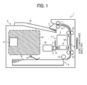
- the image forming apparatus 1 at least includes a sheet feeder 9 of a sheet feeding tray provided in the lower section to accommodate sheets P, a sheet ejector 2 of a sheet ejection tray provided in the upper section to stack sheets P ejected after image formation is executed, and a sheet conveyance path 4 arranged almost vertically from down to up sides from the sheet feeder 9 to the sheet ejector 2. Also included is an image formation section 05 that forms an image on a sheet P conveyed onto the sheet conveyance path 4.
- a sheet amount detector is provided in the sheet feeder 9 to detect an amount of sheets accommodated and stacked therein.
- the sheet amount detector includes a swingable sheet detection lever 13 changing an angle thereof in accordance with a sheet-stacking amount thereon. Thus, a sheet-stacking amount can be detected by detecting the angle.
- An ejected sheet amount detector is provided in the sheet ejector 2 to detect an amount of ejected and stacked sheets passing through the sheet ejection roller 11.
- the sheet amount detector includes a swingable sheet detection lever 14 capable of changing its angle in accordance with a sheet-stacking amount thereon. Thus, a sheet-stacking amount can be detected by detecting the angle.
- sensors not shown, measuring weight, such as a strain gauge, etc.
- measuring weight such as a strain gauge, etc.
- a lever can be omitted in the sheet ejector 9.
- problems such as partial deviation of the sheet from the lever, breakage of the lever, etc., can be avoided.
- the vibration damping mechanism 15 can be more precisely controlled due to direct detection of mass, which is more essential to a natural frequency and gravity center
- sheets P piled up on the sheet feeder 9 are initially launched being separated one by one by a sheet feeding roller 10 and a separator, not shown. Then, a pair of conveyance rollers 21 and 22 pinches the sheet. The sheet is then conveyed toward an image formation region in the image formation section 5 in a sheet conveyance direction (i.e., a sub scanning direction) as shown by arrow in the drawing.
- a sheet conveyance direction i.e., a sub scanning direction
- the image formation section 5 includes a carriage 3 and a carriage driving mechanism.
- the carriage 3 accommodates a printing head 20 and is located at one side of the apparatus, so that the printing head 20 is arranged outside (i. e., on the right side of) the sheet ejection roller 11 and the sheet-feeding roller 10.
- the printing head 20 is connected to a control substrate, not shown, by a flexible cable, not shown, drawn out from the carriage 3.
- the carriage 3 is reciprocated by a carriage driving mechanism in a main scanning direction (e.g. a sheet penetration direction in FIG. 1 ) perpendicular to a sub scanning direction, in which the sheet P is conveyed.
- the carriage driving mechanism includes a pulley connected to a main scanning motor 16, a driven pulley 23 (see FIG. 2 ) arranged facing the driving pulley 17, a timing belt 18 with a teeth portion wound around these pulleys 17 and 23, and a guide rail 19 extending in the main scanning direction.
- the carriage 3 is secured to the timing belt
- the guide rail 19 has a pair of parallel round bar penetrating respective insertion holes formed in the carriage 3, respectively.
- the carriage 3 thus slides along the pair of guide rollers 19.
- the flexible cable serves as an image signal-transmitting device from the control substrate, and is produced by printing a wiring pattern on a film having flexibility.
- the flexible cable thus transmits data between the carriage 3 and the control substrate 3 while following the movement of the carriage 3.
- An encoder 7 is provided beside the carriage 3 along the main scanning direction.
- the encoder 7 is made of transparent resin having marks of scales at a prescribed interval. By detecting the scales using an optical sensor arranged on the carriage 3, a position of the carriage 3 can be detected.
- the printing head 20 is arranged facing the sheet P between a pair of rollers 21 and 22. On a surface of the printing head facing the sheet P, there is provided ink ejection openings.
- ink ejection openings On a surface of the printing head facing the sheet P, there is provided ink ejection openings.
- the apparatus receives an inertial force from the carriage 3, thereby vibrating the apparatus. Further, in a system where a sheet feeder 9 and a sheet ejector 2 are arranged above and below the carriage 3 serving as a vibration source in the image forming apparatus of FIG. 1 , due to a difference in piling up amounts of sheets P in both of the sheet feeder 9 and the sheet ejector 2, mass of the sheets P changes significantly above and below the carriage 3.
- a conventional vibration damping system cannot effectively damp vibration of the apparatus. Accordingly, in one embodiment of the present invention, an amount of sheets in each of a sheet feeder 9 and a sheet ejector 2 is detected and the detection result is fed back to the vibration damping mechanism 15 for controlling.
- the vibration damping mechanism 15 is arranged on the left side in the apparatus.
- a control substrate and a power supply substrate are arranged in a region shown by slanted lines.
- component members needed for image formation are concentrated on a side (e.g. a right side in the drawing) where the carriage 3 and a maintenance recovery mechanism, not shown, that keeps the printing head clear, and the like are arranged. Accordingly, since (total) mass of the substrate or the like is relatively lighter than the above-described members, a gravity center of the apparatus is necessarily located on the right side in the drawing.
- the vibration damping mechanism 15 By contrast, by arranging the vibration damping mechanism 15 in the slanted line section 80, the gravity center of the apparatus is shifted to the left side in the drawing, so that the apparatus is balanced. In this way, when a principal component member arranged on one side is heavy, and a gravity center of the apparatus far shifted to the side, by arranging the vibration damping mechanism 15 in the opposite side as far as possible, the gravity center is shifted to a center of the apparatus, so that the apparatus can be stable.
- the vibration damper 15 is arranged in a space other than the slanted line section 8 where a control substrate and a power supply substrate are arranged.
- the vibration damper 15 is movably arranged in the main scanning direction in that the carriage 3 moves, and includes a vibration damper 24 having a teeth section 25, such as a rack, etc., and another driving device 26 having a meshing member 27, such as a pinion, etc., separated from the main scanning motor 16.
- a vibration damper 24 having a teeth section 25, such as a rack, etc.
- another driving device 26 having a meshing member 27, such as a pinion, etc., separated from the main scanning motor 16.
- the vibration damper 24 is moved in the main scanning direction as mentioned above. In this way, by driving the vibration damper with the other driving device than that for the carriage, load on the device for driving the carriage does not increase. Further, the vibration damper can be finely and independently controlled from the carriage.
- the vibration damping mechanism 15 can be positioned at the same height as the carriage 3 or above the same.
- the inertial force is only generated among the movement region of the carriage 3 when the carriage 3 is accelerated or decelerated as different when moving at the uniform velocity motion.
- a movement region of the vibration damper 24 is not necessarily the same as that of the carriage 3 due to driving by the separate driving device 26, and is only necessitated to move in a region corresponding to when the carriage 3 is accelerated and decelerated.
- the vibration damper 15 can be designed to move in a narrower region than the carriage 3, and thereby the apparatus can be made more compact and energy efficient.
- the vibration damper 15 includes a solenoid 28 serving as another driving device different from the main scanning motor 16, and a vibration damper 29 serving as an iron core (e.g. a plunger) of the solenoid 28.
- the vibration damper 29 is moved in the main scanning direction (i.e., a direction shown by an arrow).
- the vibration damper 29 is move rightward.
- the vibration damper 29 is moved leftward.
- the inertial force applied to the apparatus can be either reduced or cancelled.
- the vibration damper 15 is formed from the solenoid 28 and the vibration damper 29 serving as the plunger, a configuration of the vibration damper 15 is simplified decreasing numbers of parts thereof.
- the printer controller 51 receives image data 50 from an external information processing apparatus, such as a personal computer and an image reader or the like, and control the printing head 20 to eject ink drops to form an image on a sheet in accordance with the image data.
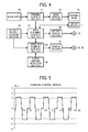
- the main scanning controller 53 calculates a control amount (e.g. a PI control amount) based on a deviation amount of a current velocity from a target velocity in accordance with a velocity profile of the carriage 3 stored in a velocity profile storage 54 as shown in FIG. 5 and an output from the encoder 7 (shown in FIG. 1 ) that detects a position of the carriage 3 in the main scanning direction.
- the main scanning controller 53 then controls the main scanning motor 16 to drive via a motor driving section 55, so that the carriage 3 is moved to execute scanning in the main scanning direction at a prescribed velocity.
- the carriage 3 may move reciprocally in accordance with a velocity profile like that shown in FIG. 5 . Specifically, premising that a positive value is assigned in an outward motion, the carriage 3 is accelerated to reach a velocity of 2.2m/s from that of 0m/s and executes a uniform motion there. During the uniform motion, liquid drops are ejected onto a printing region of a sheet by scanning thereof, so that an image is formed. The carriage 3 is controlled in the same way as mentioned above on a return path. In such a situation, an inertial force is present during acceleration and deceleration of the carriage 3 in relation to the apparatus, and is absent during the uniform motion.
- a level of acceleration of the carriage 3 depends on a printer mode designated by an operator through a personal computer or an operation panel of an apparatus. Specifically, the level is large in a high-velocity mode, intermediate, in a normal mode, and small, in a high quality mode, respectively. Vibration value of the apparatus is proportional to the level of the acceleration, such that it is large when the level is large, intermediate when the level is intermediate, and small when the level is small. Thus, an acceleration level of the vibration damper is determined depending on the printing mode.
- the vibration damping controller 56 that controls the vibration damper 15 executes vibration damping control of the apparatus during acceleration and deceleration of the carriage 3. Specifically, the vibration damping controller 56 controls the other driving devices 26 and 28 via the driving section 57 and accelerates and decelerates the vibration dampers 24 and 28 in accordance with a profile of the carriage stored in a velocity profile storage 54 according to a printer mode and an amount of sheets of each of the sheet feeding and ejectors 9 and 2 detected by a sheet amount detector 28.
- the vibration damping controller 56 monitors the respective sheet amounts of the sheet feeding and receiving sections 9 and 2, because the natural vibration frequency and the gravity center significantly change in accordance with the respective sheet amounts as mentioned above. Assuming that a contact between the apparatus and an installation surface is a fulcrum and a gravity center of the apparatus vibrates as the carriage vibrates, the harder the apparatus vibrates, the closer the gravity center approaches the fulcrum, and the easier the apparatus vibrates, the far the gravity center is separated from the fulcrum. Specifically, the larger the mass of the sheet feeder 9, the harder the apparatus vibrates, and the larger the mass of the sheet ejector 2, the easier the apparatus vibrates.
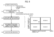
- Vibration of the apparatus in each of the first and third regions is between those of the fourth and second regions.
- the vibration damper is not driven, and accordingly vibration damping control is not necessarily executed, because acceleration and velocity of the carriage are relatively small in the high quality mode and vibration of the apparatus is also small as in the second region.
- step S1 When an operator provides a printer instruction designating a printer mode and printing contents in step S1, the main scanning controller 53 determines acceleration, an acceleration start position, and acceleration time period of a carriage in accordance with the printer mode and contents. Almost at the same time, the sheet amount detector 58 detects an amount of sheets on the sheet feeding and ejection trays in step S3. Then, acceleration, an acceleration start position, and an acceleration time period of a vibration damper is determined in accordance with those of the carriage by the vibration damping controller 56 and the amount of sheets on the sheet feeding and ejection trays in step S4.
- the above-described four regions are then considered, and an operating condition of the vibration damper is determined.
- the above-described determination of one of the four regions can be executed based on a sheet number (e.g. 100 sheets) produced at high velocity when an operator designates. Alternatively, it may be determined at every sheet printing during the printing. Finally, the carriage starts a printing operation while operating the vibration damper in step S5.
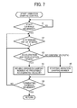
- the vibration controller 56 determines an acceleration and an acceleration time period of the vibration damper in accordance with a number of sheets on each of the sheet feeding and ejection trays detected by the sheet amount detector 58, specifically with reference to the above-described four regions in step S2.
- the vibration controller 56 determines if the carriage belongs to acceleration and deceleration regions in accordance with the velocity profile stored in the velocity profile storage 54 in step S3.
- the vibration controller 56 controls the vibration damper to move in a direction capable of canceling vibration of the apparatus caused by inertial force, which is generated by the carriage movement, at a prescribed acceleration and an acceleration time period determined in accordance with an acceleration of the carriage, when the carriage belongs to the acceleration and deceleration region.
- the vibration controller 56 controls the vibration damper to stop moving when the carriage belongs to a uniform velocity region in step S5.
- the sequence returns to step S3, and the vibration controller 56 repeats vibration control when the movement of the carriage is not completed.
- a motor for driving the vibration damper is controlled to move the vibration damper to cancel vibration of the apparatus caused by an inertial force generated by the movement of the carriage.
- another driving device than the motor for the carriage can move the vibration damper, and accordingly, the vibration damper does not need to be driven by the motor for the carriage, load on the motor driving the carriage does not increase.
- the vibration damper can be controlled in dependent from the carriage, fine control can be achieved. Further, by providing an encoder in the driving device of the vibration damper, finer control can be achieved.
- F mass ⁇ acceleration .
- the vibration damper Since the vibration damper is moved to damp vibration during acceleration and deceleration of the carriage, and is stopped when the carriage moved at uniform velocity motion, the vibration damper does not moves when an image is formed. As a result, liquid drops from the printing head do not deviate, which is generally cause by the vibration, thereby quality of an image can be maintained.
- the mass of the vibration damper is smaller than that of the carriage and executes vibration control during one of at least acceleration and deceleration times and stops controlling thereof during the uniform velocity in this way, image quality is not affected avoiding increase in mass and a size of the apparatus. Further, vibration can be effectively suppressed even as the carriage moves.
- An excursion (locus) of the sheet is not limited to the straight as in the above and can draw a letter S, where the sheet is upwardly conveyed from the sheet feeder and becomes horizontal and is further upwardly conveyed toward the sheet ejection tray passing through the carriage.
- the above-described vibration damping mechanism can include a driving device other than the main scanning motor for driving the carriage and a vibration damper linked with the driving device via an arm to swing left and right like a pendulum as the driving device rotates.
- the sheet can include an OHP or the like and is called a printer medium or sheet, to which ink drops can attach.
Landscapes
- Character Spaces And Line Spaces In Printers (AREA)
- Ink Jet (AREA)
- Controlling Sheets Or Webs (AREA)
Abstract
Description
- The present invention relates to an image forming apparatus that employs an ink jet system capable of forming an image by ejecting ink drops from a printing head mounted on a carriage onto a sheet.
- In a conventional image forming apparatus that employs an ink jet system (e.g. an inkjet printer), an image is formed by ejecting ink drops from a printing head mounted on a reciprocating carriage onto a sheet. Then, an inertial force is caused when the carriage is either accelerated or decelerated thereby vibrating an apparatus body. Especially, to increase a printing velocity, a velocity of the carriage is increased, and accordingly acceleration and deceleration become sharp. As a result, the apparatus body becomes largely vibrated and makes a user uncomfortable. Further, in a copier in which a scanner unit is mounted on a printer, vibration of the printer impacts scanning of a carriage and degrades image reading. Then, the below-described known countermeasures against the vibration have been taken, in which the object is to smooth out vibration profiles during times of acceleration and deceleration of the carriage. Alternatively, a notch filter or the like is used to filter some of a frequency band inputted to the apparatus, or a separate actuator is employed.
- An apparatus generally has a prescribed natural vibration frequency in each of various modes, such as a deflection mode, a twisting mode, etc. Thus, the apparatus largely vibrates at the prescribed natural vibration frequency in response to an input having the same natural vibration frequency as the apparatus. The above-described notch filter prevents resonance of the apparatus at the natural vibration frequencies by avoiding an input having the same natural vibration frequency as that of the machine.
- However, when a sheet moves up and down with respect to a carriage serving as a vibration source, a balance between mass of sheets ejected and stacked on a sheet ejection tray arranged on the top of the apparatus and that remaining in the sheet feeding tray arranged in the lower portion of the apparatus than the carriage changes significantly. In such a construction, a natural vibration frequency and a gravity center of the apparatus also change significantly in relation to the carriage. Further, since a natural vibration frequency also changes significantly when acceleration of the carriage is decreased or a notch filter is used, a band to avoid such an input becomes significantly wider, and acceleration of the carriage is late, so that both productivity and a width of the apparatus decrease. Similarly, when the other actuator damps vibration, and a natural vibration frequency and a gravity center of an apparatus change significantly, vibration-damping effectiveness is degraded.
- In Japanese Patent Application Laid Open Numbers
2001-138499 2005-081673 JP-2001-13849-A JP-2005-081673-A - Further, in Japanese Patent Application Laid Open Number
H3-256772 JP-H03-256772-A - However, these conventional techniques do not effectively damp the vibration of the apparatus considering the up and down movement of a gravity center of the apparatus as well as a large change in natural frequency thereof when a sheet moves up and down with respect to the carriage serving as a vibration source as mentioned above.
- Accordingly, an object of the present invention is to provide a new and novel image forming apparatus including a sheet amount detector to detect an amount of sheets accommodated in the sheet feeding tray, an ejected sheet amount detector to detect an amount of sheets ejected onto the sheet ejection tray, and a vibration damper to damp vibration of the image forming apparatus caused by movement of the carriage. A controller is also provided to control the vibration damper to damp vibration of the image forming apparatus in accordance with respective amounts of sheets and ejected sheets detected by the sheet amount detector and the ejected sheet amount detector in prescribed acceleration and deceleration regions of the carriage.
- In another aspect, the controller changes acceleration of the vibration damper in accordance with a printer mode in addition to the respective amounts of sheets and ejected sheets. The printer mode at least includes a high velocity mode, a normal mode, and a high quality mode.
- In yet another aspect, the controller changes acceleration of the vibration damper in accordance with an acceleration of the carriage in addition to the respective amounts of sheets and ejected sheets.
- In yet another aspect, detection result of the sheet amounts and the ejected sheet amounts is classified by the controller into first to fourth regions. The first region represents that the sheet amount is equal to or less than a prescribed first level and the ejected sheet amount is equal to or less than a prescribed second level, the second region represents that the sheet amount is more than the prescribed first level and the ejected sheet amount is equal to or less than the prescribed second level, the third region represents that the sheet amount is more than the prescribed first level and the ejected sheet amount is more than the prescribed second level, and the fourth region represents that the sheet amount is equal to or less than the prescribed first level and the ejected sheet amount is more than the prescribed second level. The controller changes the acceleration of the vibration damper in accordance with the first to fourth regions.
- In yet another aspect, the sheet amount detector detects an amount of sheets accommodated in the sheet-feeding tray at every printing completion. The ejected sheet amount detector detects an amount of ejected sheets ejected onto the sheet ejection tray at every printing completion.
- In yet another aspect, the controller stops operation of the vibration damper when the carriage moves at a uniform velocity region. In yet another aspect, mass of the vibration damper is smaller than that of the carriage. In yet another aspect, a moving range of the vibration damper is narrower than that of the carriage.
- In yet another aspect, the controller stops controlling the vibration damper when recognizing the second region in the high quality mode. In yet another aspect, the controller changes the acceleration of the vibration damper only in the fourth region in the high quality mode.
- A more complete appreciation of the present invention and many of the attendant advantages thereof will be readily obtained as the same becomes better understood by reference to the following detailed description when considered in connection with the accompanying drawings, wherein:
-
FIG. 1 illustrates a principal part of an image forming apparatus including a vibration damping mechanism according to one embodiment of the present invention; -
FIG. 2 illustrates an exemplary vibration damping mechanism according to one embodiment of the present invention; -
FIG. 3 illustrates another exemplary vibration damping mechanism according to one embodiment of the present invention; -
FIG. 4 illustrates an exemplary controller for controlling a carriage vibration damping mechanism according to one embodiment of the present invention; -
FIG. 5 illustrates an exemplary velocity profile of the carriage according to one embodiment of the present invention; -
FIG. 6 schematically illustrates an exemplary sequence of vibration damping control executed in the image forming apparatus and exemplary easiness of vibration of the image forming apparatus in accordance with amounts of sheets stacked on the sheet feeding and ejection trays according to one embodiment of the present invention; and -
FIG. 7 illustrates an exemplary sequence of control executed by the vibration-damping controller. - Referring now to the drawings, wherein like reference numerals designate identical or corresponding parts throughout several views, in particular in
FIG. 1 , an exemplary principle part of an image forming apparatus, such as an ink jet printer, etc., including avibration damping mechanism 15 is described. Theimage forming apparatus 1 at least includes asheet feeder 9 of a sheet feeding tray provided in the lower section to accommodate sheets P, asheet ejector 2 of a sheet ejection tray provided in the upper section to stack sheets P ejected after image formation is executed, and asheet conveyance path 4 arranged almost vertically from down to up sides from thesheet feeder 9 to thesheet ejector 2. Also included is an image formation section 05 that forms an image on a sheet P conveyed onto thesheet conveyance path 4. - A sheet amount detector is provided in the
sheet feeder 9 to detect an amount of sheets accommodated and stacked therein. The sheet amount detector includes a swingable sheet detection lever 13 changing an angle thereof in accordance with a sheet-stacking amount thereon. Thus, a sheet-stacking amount can be detected by detecting the angle. An ejected sheet amount detector is provided in thesheet ejector 2 to detect an amount of ejected and stacked sheets passing through thesheet ejection roller 11. The sheet amount detector includes a swingablesheet detection lever 14 capable of changing its angle in accordance with a sheet-stacking amount thereon. Thus, a sheet-stacking amount can be detected by detecting the angle. - Instead of the sheet detection levers 13 and 14, sensors, not shown, measuring weight, such as a strain gauge, etc., can be arranged on the bottom of the
sheet feeder 9 and thesheet ejector 2 to detect an amount of the sheets by detecting mass thereof. When the sheet amount (not a thickness) of stacked sheets is directly detected, a lever can be omitted in thesheet ejector 9. As a result, problems such as partial deviation of the sheet from the lever, breakage of the lever, etc., can be avoided. Further, thevibration damping mechanism 15 can be more precisely controlled due to direct detection of mass, which is more essential to a natural frequency and gravity center - When printing starts, sheets P piled up on the
sheet feeder 9 are initially launched being separated one by one by asheet feeding roller 10 and a separator, not shown. Then, a pair ofconveyance rollers image formation section 5 in a sheet conveyance direction (i.e., a sub scanning direction) as shown by arrow in the drawing. - The
image formation section 5 includes acarriage 3 and a carriage driving mechanism. Thecarriage 3 accommodates aprinting head 20 and is located at one side of the apparatus, so that theprinting head 20 is arranged outside (i. e., on the right side of) thesheet ejection roller 11 and the sheet-feeding roller 10. Theprinting head 20 is connected to a control substrate, not shown, by a flexible cable, not shown, drawn out from thecarriage 3. Thecarriage 3 is reciprocated by a carriage driving mechanism in a main scanning direction (e.g. a sheet penetration direction inFIG. 1 ) perpendicular to a sub scanning direction, in which the sheet P is conveyed. The carriage driving mechanism includes a pulley connected to amain scanning motor 16, a driven pulley 23 (seeFIG. 2 ) arranged facing thedriving pulley 17, atiming belt 18 with a teeth portion wound around thesepulleys guide rail 19 extending in the main scanning direction. Thecarriage 3 is secured to thetiming belt 18. - When the
pulley 17 rotates as themotor 16 operates, the carriage secured to thetiming belt 18 starts scanning in the main scanning direction. Theguide rail 19 has a pair of parallel round bar penetrating respective insertion holes formed in thecarriage 3, respectively. Thecarriage 3 thus slides along the pair ofguide rollers 19. When a rotational direction of the motor is changed, a movement direction of thecarriage 3 can be changed. Similarly, when a number of rotations of the motor is changed, a movement velocity of thecarriage 3 can be changed. - The flexible cable serves as an image signal-transmitting device from the control substrate, and is produced by printing a wiring pattern on a film having flexibility. The flexible cable thus transmits data between the
carriage 3 and thecontrol substrate 3 while following the movement of thecarriage 3. Anencoder 7 is provided beside thecarriage 3 along the main scanning direction. Theencoder 7 is made of transparent resin having marks of scales at a prescribed interval. By detecting the scales using an optical sensor arranged on thecarriage 3, a position of thecarriage 3 can be detected. - The
printing head 20 is arranged facing the sheet P between a pair ofrollers conveyance rollers printing head 20, ink drops are ejected toward the sheet P (from left to right inFIG. 1 ) from the ink ejection openings in accordance with image signal transmitted from the control substrate. Thus, a prescribed desired mage can be obtained. - In this way, by moving the sheet P in the sub scanning direction and the
carriage 3 having thehead 20 with the ink ejection (discharge) openings in the main scanning direction, an image is formed on the sheet P. Further, the sheet P having been subjected to image formation is ejected by a pair ofsheet ejection rollers 11 to thesheet ejector 2 provided on a top of the apparatus with its image surface facing down. - While the
carriage 3 is accelerated toward a printing region of a sheet and reaches a prescribed velocity, and thecarriage 3 is decelerated so that the prescribed velocity decreases down to zero after passing through the printing region, the apparatus receives an inertial force from thecarriage 3, thereby vibrating the apparatus.
Further, in a system where asheet feeder 9 and asheet ejector 2 are arranged above and below thecarriage 3 serving as a vibration source in the image forming apparatus ofFIG. 1 , due to a difference in piling up amounts of sheets P in both of thesheet feeder 9 and thesheet ejector 2, mass of the sheets P changes significantly above and below thecarriage 3. Thus, since a natural vibration frequency and a gravity center of the apparatus change significantly, a conventional vibration damping system cannot effectively damp vibration of the apparatus. Accordingly, in one embodiment of the present invention, an amount of sheets in each of asheet feeder 9 and asheet ejector 2 is detected and the detection result is fed back to thevibration damping mechanism 15 for controlling. - As shown in
FIG. 1 , thevibration damping mechanism 15 is arranged on the left side in the apparatus. A control substrate and a power supply substrate are arranged in a region shown by slanted lines. However, component members needed for image formation are concentrated on a side (e.g. a right side in the drawing) where thecarriage 3 and a maintenance recovery mechanism, not shown, that keeps the printing head clear, and the like are arranged. Accordingly, since (total) mass of the substrate or the like is relatively lighter than the above-described members, a gravity center of the apparatus is necessarily located on the right side in the drawing. By contrast, by arranging thevibration damping mechanism 15 in the slanted line section 80, the gravity center of the apparatus is shifted to the left side in the drawing, so that the apparatus is balanced. In this way, when a principal component member arranged on one side is heavy, and a gravity center of the apparatus far shifted to the side, by arranging thevibration damping mechanism 15 in the opposite side as far as possible, the gravity center is shifted to a center of the apparatus, so that the apparatus can be stable. For example, thevibration damper 15 is arranged in a space other than the slantedline section 8 where a control substrate and a power supply substrate are arranged. - Now, an exemplary configuration of the
vibration damper 15 of one embodiment of the present invention is specifically described with reference toFIG. 2 . Thevibration damper 15 is movably arranged in the main scanning direction in that thecarriage 3 moves, and includes avibration damper 24 having ateeth section 25, such as a rack, etc., and another drivingdevice 26 having a meshingmember 27, such as a pinion, etc., separated from themain scanning motor 16. Thus, when theother driving device 26 rotates and the meshingmember 27 of theother driving device 26 meshes with theteeth section 25 of thevibration damper 24, thevibration damper 24 is moved in the main scanning direction as mentioned above. In this way, by driving the vibration damper with the other driving device than that for the carriage, load on the device for driving the carriage does not increase. Further, the vibration damper can be finely and independently controlled from the carriage. - At that time, when the
carriage 3 moves in the main scanning direction, i.e., to left in the drawing, the vibration-damper 24 is moved rightward. By contrast, when thecarriage 3 moves to right in the drawing, the vibration-damper 24 is moved leftward. As a result, opposite acceleration to that applied to thecarriage 3 is applied all the time to the vibration-damper 24. Accordingly, each of inertial forces caused by thecarriage 3 and the vibration-damper 24 and applied to the apparatus is also opposite all the time, it is either reduced or cancelled. - Specifically, by equalizing the respective accelerations of the
carriage 3 and thevibration damper 24 when the respective mass of those are the same in consideration of formula (F (inertial force) = m (mass) x a (acceleration)), the same but opposite directional inertial force can be generated. Further, by increasing the acceleration of thevibration damper 24 greater than that of thecarriage 3 when the mass of thevibration damper 24 is less than that of thecarriage 3, the same but opposite directional inertial force can similarly be generated. - Further, since the
carriage 3 and thevibration damper 24 move in parallel to each other, a wasteful force is not generated, and accordingly the inertial force in a direction capable of canceling that of thecarriage 3 can be directly and effectively applied to the apparatus body. It should be noted that thevibration damping mechanism 15 can be positioned at the same height as thecarriage 3 or above the same. - Further, the inertial force is only generated among the movement region of the
carriage 3 when thecarriage 3 is accelerated or decelerated as different when moving at the uniform velocity motion. Thus, a movement region of thevibration damper 24 is not necessarily the same as that of thecarriage 3 due to driving by theseparate driving device 26, and is only necessitated to move in a region corresponding to when thecarriage 3 is accelerated and decelerated. Accordingly, thevibration damper 15 can be designed to move in a narrower region than thecarriage 3, and thereby the apparatus can be made more compact and energy efficient. - Now, another exemplary embodiment of a vibration-
damper 15 according to the present invention is described with reference toFIG. 3 . Thecarriage 3 and the main scanning mechanism have the same configurations as described above. However, according to this embodiment, thevibration damper 15 includes asolenoid 28 serving as another driving device different from themain scanning motor 16, and avibration damper 29 serving as an iron core (e.g. a plunger) of thesolenoid 28. Thus, by driving thesolenoid 28, thevibration damper 29 is moved in the main scanning direction (i.e., a direction shown by an arrow). At that moment, similar to the above, when thecarriage 3 is moved leftward in the drawing, thevibration damper 29 is move rightward. Whereas when thecarriage 3 is moved rightward in the drawing, thevibration damper 29 is moved leftward. As a result, the inertial force applied to the apparatus can be either reduced or cancelled. Further, since thevibration damper 15 is formed from thesolenoid 28 and thevibration damper 29 serving as the plunger, a configuration of thevibration damper 15 is simplified decreasing numbers of parts thereof. - Now, an exemplary controller for controlling the
carriage 3 and thevibration damper 15 is described with reference toFIG. 4 . Theprinter controller 51 receivesimage data 50 from an external information processing apparatus, such as a personal computer and an image reader or the like, and control theprinting head 20 to eject ink drops to form an image on a sheet in accordance with the image data. Themain scanning controller 53 calculates a control amount (e.g. a PI control amount) based on a deviation amount of a current velocity from a target velocity in accordance with a velocity profile of thecarriage 3 stored in avelocity profile storage 54 as shown inFIG. 5 and an output from the encoder 7 (shown inFIG. 1 ) that detects a position of thecarriage 3 in the main scanning direction. Themain scanning controller 53 then controls themain scanning motor 16 to drive via amotor driving section 55, so that thecarriage 3 is moved to execute scanning in the main scanning direction at a prescribed velocity. - The
carriage 3 may move reciprocally in accordance with a velocity profile like that shown inFIG. 5 . Specifically, premising that a positive value is assigned in an outward motion, thecarriage 3 is accelerated to reach a velocity of 2.2m/s from that of 0m/s and executes a uniform motion there. During the uniform motion, liquid drops are ejected onto a printing region of a sheet by scanning thereof, so that an image is formed. Thecarriage 3 is controlled in the same way as mentioned above on a return path. In such a situation, an inertial force is present during acceleration and deceleration of thecarriage 3 in relation to the apparatus, and is absent during the uniform motion. Further, a level of acceleration of thecarriage 3 depends on a printer mode designated by an operator through a personal computer or an operation panel of an apparatus. Specifically, the level is large in a high-velocity mode, intermediate, in a normal mode, and small, in a high quality mode, respectively. Vibration value of the apparatus is proportional to the level of the acceleration, such that it is large when the level is large, intermediate when the level is intermediate, and small when the level is small. Thus, an acceleration level of the vibration damper is determined depending on the printing mode. - Further, as shown in
FIG. 4 , when themain scanning controller 53 controls thecarriage 3 to move in a main scanning direction at a velocity corresponding to a printing mode, thevibration damping controller 56 that controls thevibration damper 15 executes vibration damping control of the apparatus during acceleration and deceleration of thecarriage 3. Specifically, thevibration damping controller 56 controls theother driving devices section 57 and accelerates and decelerates thevibration dampers velocity profile storage 54 according to a printer mode and an amount of sheets of each of the sheet feeding andejectors sheet amount detector 28. - Thus, the
vibration damping controller 56 monitors the respective sheet amounts of the sheet feeding and receivingsections sheet feeder 9, the harder the apparatus vibrates, and the larger the mass of thesheet ejector 2, the easier the apparatus vibrates. - Now, with reference to the right side drawing of four conditional first to fourth regions in
FIG. 6 , tendency of vibration of the apparatus in accordance with a number of sheets of each of the sheet ejection and feeding trays are described. As shown, when many sheets are stacked on the sheet ejection tray, and a small number of sheets are stacked on the sheet-feeding tray in the fourth region thereby the gravity center shown by a mark being located therein, acceleration of the vibration-damper is necessarily bigger considering the mass of the vibration damper, because the vibration of the apparatus becomes relatively large. Whereas when a small number of sheets are stacked on the sheet ejection tray, and many sheets are stacked on the sheet-feeding tray in the second region, acceleration of the vibration damper may be small because the vibration of the apparatus is small. Vibration of the apparatus in each of the first and third regions is between those of the fourth and second regions. Further, when the high quality mode is designated as a printer mode and sheet stacking numbers if the sheet feeding and ejection trays as in the second region, the vibration damper is not driven, and accordingly vibration damping control is not necessarily executed, because acceleration and velocity of the carriage are relatively small in the high quality mode and vibration of the apparatus is also small as in the second region. - Now, an exemplary sequence of the vibration damping control of the apparatus is described with reference to the flow chart shown on the left in
FIG. 6 . When an operator provides a printer instruction designating a printer mode and printing contents in step S1, themain scanning controller 53 determines acceleration, an acceleration start position, and acceleration time period of a carriage in accordance with the printer mode and contents. Almost at the same time, thesheet amount detector 58 detects an amount of sheets on the sheet feeding and ejection trays in step S3. Then, acceleration, an acceleration start position, and an acceleration time period of a vibration damper is determined in accordance with those of the carriage by thevibration damping controller 56 and the amount of sheets on the sheet feeding and ejection trays in step S4.
At this moment, the number of sheets on each of the sheet feeding and ejection trays is detected, the above-described four regions are then considered, and an operating condition of the vibration damper is determined. The above-described determination of one of the four regions can be executed based on a sheet number (e.g. 100 sheets) produced at high velocity when an operator designates. Alternatively, it may be determined at every sheet printing during the printing. Finally, the carriage starts a printing operation while operating the vibration damper in step S5. - Now, an exemplary control sequence executed by the
vibration controller 56 is described with reference toFIG. 7 . When themain scanning controller 53 controls the carriage to start main scanning movement at an acceleration in accordance with a printing mode in step S1, thevibration controller 56 determines an acceleration and an acceleration time period of the vibration damper in accordance with a number of sheets on each of the sheet feeding and ejection trays detected by thesheet amount detector 58, specifically with reference to the above-described four regions in step S2. Thevibration controller 56 then determines if the carriage belongs to acceleration and deceleration regions in accordance with the velocity profile stored in thevelocity profile storage 54 in step S3. Thevibration controller 56 controls the vibration damper to move in a direction capable of canceling vibration of the apparatus caused by inertial force, which is generated by the carriage movement, at a prescribed acceleration and an acceleration time period determined in accordance with an acceleration of the carriage, when the carriage belongs to the acceleration and deceleration region. Thevibration controller 56 controls the vibration damper to stop moving when the carriage belongs to a uniform velocity region in step S5.
The sequence returns to step S3, and thevibration controller 56 repeats vibration control when the movement of the carriage is not completed. - However, a number of sheets on the sheet feeding and ejection trays and weight thereof are significantly different between first sheet and 100th sheet when 100 sheets are printed. Further, since some amount of sheets is extracted from the sheet feeding and ejection trays during printing, determination of the region can vary. Thus, belonging to one of four regions can be determined (as shown by a dotted line arrow) returning to step S2 per one or multiple number of sheet printings. As a result, acceleration of the vibration damper can be more precisely determined.
- In this way, a motor for driving the vibration damper is controlled to move the vibration damper to cancel vibration of the apparatus caused by an inertial force generated by the movement of the carriage. At this moment, since another driving device than the motor for the carriage can move the vibration damper, and accordingly, the vibration damper does not need to be driven by the motor for the carriage, load on the motor driving the carriage does not increase. In addition, since the vibration damper can be controlled in dependent from the carriage, fine control can be achieved. Further, by providing an encoder in the driving device of the vibration damper, finer control can be achieved.
- Further, since an impactive force F is calculated by the following formula, mass of the vibration damper can be smaller than that of carriage, and almost the same impactive force F can be obtained if an acceleration is increased in proportion thereto;
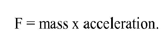
As a result, vibration of the apparatus caused by the inertial force of the carriage can be cancelled. Further, by making the vibration damper light and compact, increase of the mass and a size of the whole apparatus can be minimized. - Since the vibration damper is moved to damp vibration during acceleration and deceleration of the carriage, and is stopped when the carriage moved at uniform velocity motion, the vibration damper does not moves when an image is formed. As a result, liquid drops from the printing head do not deviate, which is generally cause by the vibration, thereby quality of an image can be maintained.
- The mass of the vibration damper is smaller than that of the carriage and executes vibration control during one of at least acceleration and deceleration times and stops controlling thereof during the uniform velocity in this way, image quality is not affected avoiding increase in mass and a size of the apparatus. Further, vibration can be effectively suppressed even as the carriage moves.
- An excursion (locus) of the sheet is not limited to the straight as in the above and can draw a letter S, where the sheet is upwardly conveyed from the sheet feeder and becomes horizontal and is further upwardly conveyed toward the sheet ejection tray passing through the carriage.
- Further, the above-described vibration damping mechanism can include a driving device other than the main scanning motor for driving the carriage and a vibration damper linked with the driving device via an arm to swing left and right like a pendulum as the driving device rotates. Further, the sheet can include an OHP or the like and is called a printer medium or sheet, to which ink drops can attach.
- Numerous additional modifications and variations of the present invention are possible in latent image of the above teachings. It is therefore to be understood that within the scope of the appended claims, the present invention may be practiced otherwise that as specifically described herein.
- With the invention, even when a sheet moves up and down than a carriage serving as a vibration source, vibration of an apparatus can be effectively damped.
Claims (10)
- An image forming apparatus comprising:a sheet feeding tray configured to accommodate sheets;a printing head configured to form an image by ejecting ink drops onto a sheet conveyed from the sheet feeding tray;a carriage configured to reciprocate in a main scanning direction carrying the printing head, said carriage being arranged above the sheet feeding tray;a sheet ejection tray configured to stack sheets bearing images formed by the printing head thereon, said sheet ejection tray being arranged above the carriage;a sheet amount detector configured to detect an amount of sheets accommodated in the sheet feeding tray;an ejected sheet amount detector configured to detect an amount of sheets ejected onto the sheet ejection tray;a vibration damper configured to damp vibration of the image forming apparatus caused by movement of the carriage; anda controller configured to control the vibration damper to damp vibration of the image forming apparatus in accordance with respective amounts of sheets and ejected sheets detected by the sheet amount detector and the ejected sheet amount detector in prescribed acceleration and deceleration regions of the carriage.
- The image forming apparatus as claimed in claim 1, wherein said controller changes acceleration of the vibration damper in accordance with a printer mode in addition to the respective amounts of sheets and ejected sheets, said printer mode at least including a high velocity mode, a normal mode, and a high quality mode.
- The image forming apparatus as claimed in claim 1 OR 2, wherein said controller changes acceleration of the vibration damper in accordance with an acceleration of the carriage in addition to the respective amounts of sheets and ejected sheets.
- The image forming apparatus as claimed in claim 1, 2 or 3, wherein a detection result of the sheet amount and the ejected sheet amount is classified by the controller into first to fourth regions,
wherein said first region represents that the sheet amount is equal to or less than a prescribed first level and the ejected sheet amount is equal to or less than a prescribed second level, said second region represents that the sheet amount is more than the prescribed first level and the ejected sheet amount is equal to or less than the prescribed second level, said third region represents that the sheet amount is more than the prescribed first level and the ejected sheet amount is more than the prescribed second level, and said fourth region represents that the sheet amount is equal to or less than the prescribed first level and the ejected sheet amount is more than the prescribed second level, and
wherein said controller changes the acceleration of the vibration damper in accordance with the first to fourth regions. - The image forming apparatus as claimed in claim 4, wherein said controller stops controlling the vibration damper in the second region in the high quality mode.
- The image forming apparatus as claimed in claim 4, wherein said controller changes the acceleration of the vibration damper only in the fourth region in the high quality mode.
- The image forming apparatus as claimed in any one of claims 1 to 6, wherein the sheet amount detector detects an amount of sheets accommodated in the sheet feeding tray at every printing completion, and
wherein the ejected sheet amount detector detects an amount of ejected sheets ejected onto the sheet ejection tray at every printing completion. - The image forming apparatus as claimed in any one of claims 1 to 7, wherein said controller stops operation of the vibration damper when the carriage moves at a uniform velocity region.
- The image forming apparatus as claimed in any one of claims 1 to 8, wherein mass of the vibration damper is smaller than that of the carriage.
- The image forming apparatus as claimed in any one of claims 1 to 9, wherein a moving range of the vibration damper is narrower than that of the carriage.
Applications Claiming Priority (1)
| Application Number | Priority Date | Filing Date | Title |
|---|---|---|---|
| JP2009282739A JP5365494B2 (en) | 2009-12-14 | 2009-12-14 | Image forming apparatus |
Publications (3)
| Publication Number | Publication Date |
|---|---|
| EP2332732A2 true EP2332732A2 (en) | 2011-06-15 |
| EP2332732A3 EP2332732A3 (en) | 2011-06-22 |
| EP2332732B1 EP2332732B1 (en) | 2013-05-08 |
Family
ID=43825339
Family Applications (1)
| Application Number | Title | Priority Date | Filing Date |
|---|---|---|---|
| EP10194567.3A Not-in-force EP2332732B1 (en) | 2009-12-14 | 2010-12-10 | Image forming apparatus capable of effectively damping vibration |
Country Status (4)
| Country | Link |
|---|---|
| US (1) | US8419156B2 (en) |
| EP (1) | EP2332732B1 (en) |
| JP (1) | JP5365494B2 (en) |
| CN (1) | CN102166893B (en) |
Families Citing this family (23)
| Publication number | Priority date | Publication date | Assignee | Title |
|---|---|---|---|---|
| JP5533457B2 (en) | 2010-09-02 | 2014-06-25 | 株式会社リコー | Image forming apparatus |
| JP5593981B2 (en) | 2010-09-03 | 2014-09-24 | 株式会社リコー | Image forming apparatus |
| US8544986B2 (en) | 2010-09-11 | 2013-10-01 | Ricoh Company, Ltd. | Image forming apparatus |
| JP5605140B2 (en) | 2010-09-30 | 2014-10-15 | 株式会社リコー | Image forming apparatus |
| JP5664145B2 (en) | 2010-11-09 | 2015-02-04 | 株式会社リコー | Image forming apparatus |
| JP5699552B2 (en) | 2010-11-09 | 2015-04-15 | 株式会社リコー | Image forming apparatus |
| JP2012111159A (en) | 2010-11-25 | 2012-06-14 | Ricoh Co Ltd | Image forming apparatus |
| JP5817281B2 (en) | 2011-07-19 | 2015-11-18 | 株式会社リコー | Image forming apparatus |
| US9121832B2 (en) * | 2011-09-01 | 2015-09-01 | Honeywell Asca Inc. | Apparatus and method for reducing vibrations of scanning sensors in web manufacturing or processing systems |
| JP6053372B2 (en) * | 2012-07-31 | 2016-12-27 | キヤノン株式会社 | Print control apparatus and print control method |
| JP6061537B2 (en) * | 2012-07-31 | 2017-01-18 | キヤノン株式会社 | Printing method, printing apparatus, and printing sheet used therefor |
| JP6197376B2 (en) | 2012-09-18 | 2017-09-20 | 株式会社リコー | Image forming apparatus |
| JP6083179B2 (en) | 2012-10-01 | 2017-02-22 | 株式会社リコー | Image forming apparatus |
| JP6236774B2 (en) * | 2012-11-29 | 2017-11-29 | 株式会社リコー | Image forming apparatus and program |
| JP6119261B2 (en) | 2013-01-18 | 2017-04-26 | 株式会社リコー | Image forming apparatus |
| CN105072308B (en) * | 2015-08-19 | 2017-11-28 | 金华市至美包装有限公司 | Against shock image-scanning device |
| ITUB20154785A1 (en) * | 2015-11-03 | 2017-05-03 | Panotec Srl | APPARATUS FOR THE CONTROLLED HANDLING OF PRINTING UNITS AND MACHINE FOR THE PRODUCTION OF PACKAGING INCORPORATING SUCH EQUIPMENT |
| US9505572B1 (en) * | 2016-01-06 | 2016-11-29 | International Business Machines Corporation | Printer with automatic paper sheet count discovery |
| US9844932B2 (en) * | 2016-01-28 | 2017-12-19 | Riso Kagaku Corporation | Inkjet printing machine |
| US11305545B2 (en) * | 2017-12-18 | 2022-04-19 | Hewlett-Packard Development Company, L.P. | Rendering fluid delivery |
| JP7075616B2 (en) | 2018-03-17 | 2022-05-26 | 株式会社リコー | Image forming device and image forming device main body |
| JP7101340B2 (en) | 2018-03-17 | 2022-07-15 | 株式会社リコー | Image forming device |
| US11264929B2 (en) * | 2019-09-18 | 2022-03-01 | Rockwell Automation Technologies, Inc. | Systems and methods for non-rigid load vibration control |
Citations (4)
| Publication number | Priority date | Publication date | Assignee | Title |
|---|---|---|---|---|
| JPH03256772A (en) | 1990-03-06 | 1991-11-15 | Minoru Tanabe | Oscillation control structure of serial printer |
| JP2001013849A (en) | 1999-06-29 | 2001-01-19 | Canon Inc | Process cartridge and image forming apparatus |
| JP2001138499A (en) | 1999-11-11 | 2001-05-22 | Seiko Epson Corp | Ink jet recording device |
| JP2005081673A (en) | 2003-09-08 | 2005-03-31 | Ricoh Co Ltd | Carriage transport mechanism, recording head transport apparatus, image forming apparatus, document reading apparatus, and copying machine |
Family Cites Families (14)
| Publication number | Priority date | Publication date | Assignee | Title |
|---|---|---|---|---|
| JPH0790655B2 (en) | 1984-04-23 | 1995-10-04 | 株式会社リコー | Ink sheet peeling device for thermal transfer printer |
| JPS6349942U (en) * | 1986-09-18 | 1988-04-05 | ||
| JP4120040B2 (en) * | 1998-03-09 | 2008-07-16 | コニカミノルタホールディングス株式会社 | Recording device |
| JP3369488B2 (en) | 1998-10-21 | 2003-01-20 | 富士通株式会社 | Shuttle control method |
| JP2001078496A (en) * | 1999-09-03 | 2001-03-23 | Canon Inc | Drive control device for stepping motor and drive control method therefor |
| JP2002172825A (en) | 2000-12-08 | 2002-06-18 | Hitachi Koki Co Ltd | Shuttle control method for printer |
| JP3787510B2 (en) * | 2001-09-07 | 2006-06-21 | キヤノン株式会社 | Recording device |
| JP4250542B2 (en) * | 2004-01-30 | 2009-04-08 | キヤノン株式会社 | Inkjet recording apparatus and inkjet recording method |
| JP4437536B2 (en) * | 2004-06-17 | 2010-03-24 | ブラザー工業株式会社 | Image forming apparatus |
| US7350758B2 (en) * | 2004-09-24 | 2008-04-01 | Lexmark International, Inc. | Module for mounting a MEMS device |
| JP4679316B2 (en) * | 2005-09-16 | 2011-04-27 | 株式会社リコー | Image forming apparatus |
| JP2009084052A (en) * | 2007-09-14 | 2009-04-23 | Ricoh Co Ltd | Paper feeding device and image forming apparatus |
| JP2009160854A (en) | 2008-01-08 | 2009-07-23 | Ricoh Co Ltd | Image forming apparatus |
| JP2010064469A (en) | 2008-09-13 | 2010-03-25 | Ricoh Co Ltd | Image forming apparatus |
-
2009
- 2009-12-14 JP JP2009282739A patent/JP5365494B2/en not_active Expired - Fee Related
-
2010
- 2010-12-09 US US12/964,238 patent/US8419156B2/en not_active Expired - Fee Related
- 2010-12-10 EP EP10194567.3A patent/EP2332732B1/en not_active Not-in-force
- 2010-12-14 CN CN201010609708.9A patent/CN102166893B/en not_active Expired - Fee Related
Patent Citations (4)
| Publication number | Priority date | Publication date | Assignee | Title |
|---|---|---|---|---|
| JPH03256772A (en) | 1990-03-06 | 1991-11-15 | Minoru Tanabe | Oscillation control structure of serial printer |
| JP2001013849A (en) | 1999-06-29 | 2001-01-19 | Canon Inc | Process cartridge and image forming apparatus |
| JP2001138499A (en) | 1999-11-11 | 2001-05-22 | Seiko Epson Corp | Ink jet recording device |
| JP2005081673A (en) | 2003-09-08 | 2005-03-31 | Ricoh Co Ltd | Carriage transport mechanism, recording head transport apparatus, image forming apparatus, document reading apparatus, and copying machine |
Also Published As
| Publication number | Publication date |
|---|---|
| EP2332732B1 (en) | 2013-05-08 |
| EP2332732A3 (en) | 2011-06-22 |
| JP2011121330A (en) | 2011-06-23 |
| CN102166893A (en) | 2011-08-31 |
| CN102166893B (en) | 2013-06-26 |
| JP5365494B2 (en) | 2013-12-11 |
| US8419156B2 (en) | 2013-04-16 |
| US20110141181A1 (en) | 2011-06-16 |
Similar Documents
| Publication | Publication Date | Title |
|---|---|---|
| EP2332732B1 (en) | Image forming apparatus capable of effectively damping vibration | |
| JP5365535B2 (en) | Image forming apparatus | |
| JP2010052417A (en) | Image forming apparatus | |
| JP5938875B2 (en) | Image forming apparatus | |
| US8544986B2 (en) | Image forming apparatus | |
| US20020075495A1 (en) | Recording apparatus | |
| JP2010064469A (en) | Image forming apparatus | |
| JP2008068413A (en) | Printing device | |
| JP4212414B2 (en) | Motor stop control method and motor stop control device | |
| JP5299157B2 (en) | Image forming apparatus | |
| US8164807B2 (en) | Image recording apparatus and control method for same | |
| US8585178B2 (en) | Carriage printer with adaptive motion control | |
| US20130257983A1 (en) | Image Recording Apparatus | |
| JP5338554B2 (en) | Image forming apparatus | |
| JP2024154699A (en) | Sheet stacking device and image forming apparatus | |
| JP5942752B2 (en) | Sheet discharge apparatus, sheet stacking detection method, sheet stacking detection program, and image forming apparatus including the sheet discharge apparatus | |
| JP2007090875A (en) | Image forming apparatus | |
| JP2009091126A (en) | Sheet post-processing device and image forming device | |
| CN100506538C (en) | Recording device, recording material conveying method, liquid ejecting device | |
| US20070127967A1 (en) | Image forming apparatus | |
| JP5220645B2 (en) | Paper receiving device | |
| JP2006192624A (en) | Image forming apparatus | |
| JP2011037119A (en) | Image forming device | |
| JP5267152B2 (en) | Image forming apparatus | |
| JP2011167866A (en) | Image forming apparatus |
Legal Events
| Date | Code | Title | Description |
|---|---|---|---|
| PUAI | Public reference made under article 153(3) epc to a published international application that has entered the european phase |
Free format text: ORIGINAL CODE: 0009012 |
|
| PUAL | Search report despatched |
Free format text: ORIGINAL CODE: 0009013 |
|
| AK | Designated contracting states |
Kind code of ref document: A2 Designated state(s): AL AT BE BG CH CY CZ DE DK EE ES FI FR GB GR HR HU IE IS IT LI LT LU LV MC MK MT NL NO PL PT RO RS SE SI SK SM TR |
|
| AX | Request for extension of the european patent |
Extension state: BA ME |
|
| AK | Designated contracting states |
Kind code of ref document: A3 Designated state(s): AL AT BE BG CH CY CZ DE DK EE ES FI FR GB GR HR HU IE IS IT LI LT LU LV MC MK MT NL NO PL PT RO RS SE SI SK SM TR |
|
| AX | Request for extension of the european patent |
Extension state: BA ME |
|
| RIC1 | Information provided on ipc code assigned before grant |
Ipc: B41J 29/10 20060101ALI20110516BHEP Ipc: B41J 29/393 20060101AFI20110411BHEP |
|
| 17P | Request for examination filed |
Effective date: 20110819 |
|
| GRAP | Despatch of communication of intention to grant a patent |
Free format text: ORIGINAL CODE: EPIDOSNIGR1 |
|
| GRAS | Grant fee paid |
Free format text: ORIGINAL CODE: EPIDOSNIGR3 |
|
| GRAA | (expected) grant |
Free format text: ORIGINAL CODE: 0009210 |
|
| AK | Designated contracting states |
Kind code of ref document: B1 Designated state(s): AL AT BE BG CH CY CZ DE DK EE ES FI FR GB GR HR HU IE IS IT LI LT LU LV MC MK MT NL NO PL PT RO RS SE SI SK SM TR |
|
| REG | Reference to a national code |
Ref country code: GB Ref legal event code: FG4D |
|
| REG | Reference to a national code |
Ref country code: AT Ref legal event code: REF Ref document number: 610874 Country of ref document: AT Kind code of ref document: T Effective date: 20130515 Ref country code: CH Ref legal event code: EP |
|
| REG | Reference to a national code |
Ref country code: IE Ref legal event code: FG4D |
|
| REG | Reference to a national code |
Ref country code: DE Ref legal event code: R096 Ref document number: 602010006899 Country of ref document: DE Effective date: 20130704 |
|
| REG | Reference to a national code |
Ref country code: AT Ref legal event code: MK05 Ref document number: 610874 Country of ref document: AT Kind code of ref document: T Effective date: 20130508 |
|
| REG | Reference to a national code |
Ref country code: LT Ref legal event code: MG4D |
|
| REG | Reference to a national code |
Ref country code: NL Ref legal event code: VDEP Effective date: 20130508 |
|
| PG25 | Lapsed in a contracting state [announced via postgrant information from national office to epo] |
Ref country code: SE Free format text: LAPSE BECAUSE OF FAILURE TO SUBMIT A TRANSLATION OF THE DESCRIPTION OR TO PAY THE FEE WITHIN THE PRESCRIBED TIME-LIMIT Effective date: 20130508 Ref country code: IS Free format text: LAPSE BECAUSE OF FAILURE TO SUBMIT A TRANSLATION OF THE DESCRIPTION OR TO PAY THE FEE WITHIN THE PRESCRIBED TIME-LIMIT Effective date: 20130908 Ref country code: PT Free format text: LAPSE BECAUSE OF FAILURE TO SUBMIT A TRANSLATION OF THE DESCRIPTION OR TO PAY THE FEE WITHIN THE PRESCRIBED TIME-LIMIT Effective date: 20130909 Ref country code: GR Free format text: LAPSE BECAUSE OF FAILURE TO SUBMIT A TRANSLATION OF THE DESCRIPTION OR TO PAY THE FEE WITHIN THE PRESCRIBED TIME-LIMIT Effective date: 20130809 Ref country code: NO Free format text: LAPSE BECAUSE OF FAILURE TO SUBMIT A TRANSLATION OF THE DESCRIPTION OR TO PAY THE FEE WITHIN THE PRESCRIBED TIME-LIMIT Effective date: 20130808 Ref country code: ES Free format text: LAPSE BECAUSE OF FAILURE TO SUBMIT A TRANSLATION OF THE DESCRIPTION OR TO PAY THE FEE WITHIN THE PRESCRIBED TIME-LIMIT Effective date: 20130819 Ref country code: AT Free format text: LAPSE BECAUSE OF FAILURE TO SUBMIT A TRANSLATION OF THE DESCRIPTION OR TO PAY THE FEE WITHIN THE PRESCRIBED TIME-LIMIT Effective date: 20130508 Ref country code: FI Free format text: LAPSE BECAUSE OF FAILURE TO SUBMIT A TRANSLATION OF THE DESCRIPTION OR TO PAY THE FEE WITHIN THE PRESCRIBED TIME-LIMIT Effective date: 20130508 Ref country code: LT Free format text: LAPSE BECAUSE OF FAILURE TO SUBMIT A TRANSLATION OF THE DESCRIPTION OR TO PAY THE FEE WITHIN THE PRESCRIBED TIME-LIMIT Effective date: 20130508 Ref country code: SI Free format text: LAPSE BECAUSE OF FAILURE TO SUBMIT A TRANSLATION OF THE DESCRIPTION OR TO PAY THE FEE WITHIN THE PRESCRIBED TIME-LIMIT Effective date: 20130508 |
|
| PG25 | Lapsed in a contracting state [announced via postgrant information from national office to epo] |
Ref country code: HR Free format text: LAPSE BECAUSE OF FAILURE TO SUBMIT A TRANSLATION OF THE DESCRIPTION OR TO PAY THE FEE WITHIN THE PRESCRIBED TIME-LIMIT Effective date: 20130508 Ref country code: CY Free format text: LAPSE BECAUSE OF FAILURE TO SUBMIT A TRANSLATION OF THE DESCRIPTION OR TO PAY THE FEE WITHIN THE PRESCRIBED TIME-LIMIT Effective date: 20130508 Ref country code: PL Free format text: LAPSE BECAUSE OF FAILURE TO SUBMIT A TRANSLATION OF THE DESCRIPTION OR TO PAY THE FEE WITHIN THE PRESCRIBED TIME-LIMIT Effective date: 20130508 Ref country code: BG Free format text: LAPSE BECAUSE OF FAILURE TO SUBMIT A TRANSLATION OF THE DESCRIPTION OR TO PAY THE FEE WITHIN THE PRESCRIBED TIME-LIMIT Effective date: 20130808 Ref country code: RS Free format text: LAPSE BECAUSE OF FAILURE TO SUBMIT A TRANSLATION OF THE DESCRIPTION OR TO PAY THE FEE WITHIN THE PRESCRIBED TIME-LIMIT Effective date: 20130508 |
|
| PG25 | Lapsed in a contracting state [announced via postgrant information from national office to epo] |
Ref country code: LV Free format text: LAPSE BECAUSE OF FAILURE TO SUBMIT A TRANSLATION OF THE DESCRIPTION OR TO PAY THE FEE WITHIN THE PRESCRIBED TIME-LIMIT Effective date: 20130508 |
|
| PG25 | Lapsed in a contracting state [announced via postgrant information from national office to epo] |
Ref country code: SK Free format text: LAPSE BECAUSE OF FAILURE TO SUBMIT A TRANSLATION OF THE DESCRIPTION OR TO PAY THE FEE WITHIN THE PRESCRIBED TIME-LIMIT Effective date: 20130508 Ref country code: EE Free format text: LAPSE BECAUSE OF FAILURE TO SUBMIT A TRANSLATION OF THE DESCRIPTION OR TO PAY THE FEE WITHIN THE PRESCRIBED TIME-LIMIT Effective date: 20130508 Ref country code: CZ Free format text: LAPSE BECAUSE OF FAILURE TO SUBMIT A TRANSLATION OF THE DESCRIPTION OR TO PAY THE FEE WITHIN THE PRESCRIBED TIME-LIMIT Effective date: 20130508 Ref country code: DK Free format text: LAPSE BECAUSE OF FAILURE TO SUBMIT A TRANSLATION OF THE DESCRIPTION OR TO PAY THE FEE WITHIN THE PRESCRIBED TIME-LIMIT Effective date: 20130508 Ref country code: BE Free format text: LAPSE BECAUSE OF FAILURE TO SUBMIT A TRANSLATION OF THE DESCRIPTION OR TO PAY THE FEE WITHIN THE PRESCRIBED TIME-LIMIT Effective date: 20130508 |
|
| PG25 | Lapsed in a contracting state [announced via postgrant information from national office to epo] |
Ref country code: NL Free format text: LAPSE BECAUSE OF FAILURE TO SUBMIT A TRANSLATION OF THE DESCRIPTION OR TO PAY THE FEE WITHIN THE PRESCRIBED TIME-LIMIT Effective date: 20130508 Ref country code: RO Free format text: LAPSE BECAUSE OF FAILURE TO SUBMIT A TRANSLATION OF THE DESCRIPTION OR TO PAY THE FEE WITHIN THE PRESCRIBED TIME-LIMIT Effective date: 20130508 Ref country code: IT Free format text: LAPSE BECAUSE OF FAILURE TO SUBMIT A TRANSLATION OF THE DESCRIPTION OR TO PAY THE FEE WITHIN THE PRESCRIBED TIME-LIMIT Effective date: 20130508 |
|
| PLBE | No opposition filed within time limit |
Free format text: ORIGINAL CODE: 0009261 |
|
| STAA | Information on the status of an ep patent application or granted ep patent |
Free format text: STATUS: NO OPPOSITION FILED WITHIN TIME LIMIT |
|
| 26N | No opposition filed |
Effective date: 20140211 |
|
| REG | Reference to a national code |
Ref country code: DE Ref legal event code: R097 Ref document number: 602010006899 Country of ref document: DE Effective date: 20140211 |
|
| PG25 | Lapsed in a contracting state [announced via postgrant information from national office to epo] |
Ref country code: LU Free format text: LAPSE BECAUSE OF FAILURE TO SUBMIT A TRANSLATION OF THE DESCRIPTION OR TO PAY THE FEE WITHIN THE PRESCRIBED TIME-LIMIT Effective date: 20131210 Ref country code: MC Free format text: LAPSE BECAUSE OF FAILURE TO SUBMIT A TRANSLATION OF THE DESCRIPTION OR TO PAY THE FEE WITHIN THE PRESCRIBED TIME-LIMIT Effective date: 20130508 |
|
| REG | Reference to a national code |
Ref country code: IE Ref legal event code: MM4A |
|
| PG25 | Lapsed in a contracting state [announced via postgrant information from national office to epo] |
Ref country code: IE Free format text: LAPSE BECAUSE OF NON-PAYMENT OF DUE FEES Effective date: 20131210 |
|
| PG25 | Lapsed in a contracting state [announced via postgrant information from national office to epo] |
Ref country code: SM Free format text: LAPSE BECAUSE OF FAILURE TO SUBMIT A TRANSLATION OF THE DESCRIPTION OR TO PAY THE FEE WITHIN THE PRESCRIBED TIME-LIMIT Effective date: 20130508 |
|
| PG25 | Lapsed in a contracting state [announced via postgrant information from national office to epo] |
Ref country code: TR Free format text: LAPSE BECAUSE OF FAILURE TO SUBMIT A TRANSLATION OF THE DESCRIPTION OR TO PAY THE FEE WITHIN THE PRESCRIBED TIME-LIMIT Effective date: 20130508 |
|
| PG25 | Lapsed in a contracting state [announced via postgrant information from national office to epo] |
Ref country code: HU Free format text: LAPSE BECAUSE OF FAILURE TO SUBMIT A TRANSLATION OF THE DESCRIPTION OR TO PAY THE FEE WITHIN THE PRESCRIBED TIME-LIMIT; INVALID AB INITIO Effective date: 20101210 Ref country code: MK Free format text: LAPSE BECAUSE OF FAILURE TO SUBMIT A TRANSLATION OF THE DESCRIPTION OR TO PAY THE FEE WITHIN THE PRESCRIBED TIME-LIMIT Effective date: 20130508 |
|
| REG | Reference to a national code |
Ref country code: CH Ref legal event code: PL |
|
| PG25 | Lapsed in a contracting state [announced via postgrant information from national office to epo] |
Ref country code: MT Free format text: LAPSE BECAUSE OF FAILURE TO SUBMIT A TRANSLATION OF THE DESCRIPTION OR TO PAY THE FEE WITHIN THE PRESCRIBED TIME-LIMIT Effective date: 20130508 |
|
| PG25 | Lapsed in a contracting state [announced via postgrant information from national office to epo] |
Ref country code: CH Free format text: LAPSE BECAUSE OF NON-PAYMENT OF DUE FEES Effective date: 20141231 Ref country code: LI Free format text: LAPSE BECAUSE OF NON-PAYMENT OF DUE FEES Effective date: 20141231 |
|
| REG | Reference to a national code |
Ref country code: FR Ref legal event code: PLFP Year of fee payment: 6 |
|
| REG | Reference to a national code |
Ref country code: FR Ref legal event code: PLFP Year of fee payment: 7 |
|
| REG | Reference to a national code |
Ref country code: FR Ref legal event code: PLFP Year of fee payment: 8 |
|
| PG25 | Lapsed in a contracting state [announced via postgrant information from national office to epo] |
Ref country code: AL Free format text: LAPSE BECAUSE OF FAILURE TO SUBMIT A TRANSLATION OF THE DESCRIPTION OR TO PAY THE FEE WITHIN THE PRESCRIBED TIME-LIMIT Effective date: 20130508 |
|
| PGFP | Annual fee paid to national office [announced via postgrant information from national office to epo] |
Ref country code: DE Payment date: 20201211 Year of fee payment: 11 Ref country code: FR Payment date: 20201223 Year of fee payment: 11 |
|
| REG | Reference to a national code |
Ref country code: DE Ref legal event code: R119 Ref document number: 602010006899 Country of ref document: DE |
|
| PG25 | Lapsed in a contracting state [announced via postgrant information from national office to epo] |
Ref country code: DE Free format text: LAPSE BECAUSE OF NON-PAYMENT OF DUE FEES Effective date: 20220701 |
|
| PG25 | Lapsed in a contracting state [announced via postgrant information from national office to epo] |
Ref country code: FR Free format text: LAPSE BECAUSE OF NON-PAYMENT OF DUE FEES Effective date: 20211231 |
|
| PGFP | Annual fee paid to national office [announced via postgrant information from national office to epo] |
Ref country code: GB Payment date: 20231220 Year of fee payment: 14 |
|
| GBPC | Gb: european patent ceased through non-payment of renewal fee |
Effective date: 20241210 |
|
| PG25 | Lapsed in a contracting state [announced via postgrant information from national office to epo] |
Ref country code: GB Free format text: LAPSE BECAUSE OF NON-PAYMENT OF DUE FEES Effective date: 20241210 |