EP2332606A2 - Mask system - Google Patents
Mask system Download PDFInfo
- Publication number
- EP2332606A2 EP2332606A2 EP20100193196 EP10193196A EP2332606A2 EP 2332606 A2 EP2332606 A2 EP 2332606A2 EP 20100193196 EP20100193196 EP 20100193196 EP 10193196 A EP10193196 A EP 10193196A EP 2332606 A2 EP2332606 A2 EP 2332606A2
- Authority
- EP
- European Patent Office
- Prior art keywords
- frame
- mask assembly
- headgear
- assembly according
- mask
- Prior art date
- Legal status (The legal status is an assumption and is not a legal conclusion. Google has not performed a legal analysis and makes no representation as to the accuracy of the status listed.)
- Granted
Links
Images


Classifications
-
- A—HUMAN NECESSITIES
- A61—MEDICAL OR VETERINARY SCIENCE; HYGIENE
- A61M—DEVICES FOR INTRODUCING MEDIA INTO, OR ONTO, THE BODY; DEVICES FOR TRANSDUCING BODY MEDIA OR FOR TAKING MEDIA FROM THE BODY; DEVICES FOR PRODUCING OR ENDING SLEEP OR STUPOR
- A61M16/00—Devices for influencing the respiratory system of patients by gas treatment, e.g. mouth-to-mouth respiration; Tracheal tubes
- A61M16/06—Respiratory or anaesthetic masks
- A61M16/0605—Means for improving the adaptation of the mask to the patient
- A61M16/0633—Means for improving the adaptation of the mask to the patient with forehead support
-
- A—HUMAN NECESSITIES
- A61—MEDICAL OR VETERINARY SCIENCE; HYGIENE
- A61M—DEVICES FOR INTRODUCING MEDIA INTO, OR ONTO, THE BODY; DEVICES FOR TRANSDUCING BODY MEDIA OR FOR TAKING MEDIA FROM THE BODY; DEVICES FOR PRODUCING OR ENDING SLEEP OR STUPOR
- A61M16/00—Devices for influencing the respiratory system of patients by gas treatment, e.g. mouth-to-mouth respiration; Tracheal tubes
- A61M16/06—Respiratory or anaesthetic masks
- A61M16/0683—Holding devices therefor
-
- A—HUMAN NECESSITIES
- A61—MEDICAL OR VETERINARY SCIENCE; HYGIENE
- A61M—DEVICES FOR INTRODUCING MEDIA INTO, OR ONTO, THE BODY; DEVICES FOR TRANSDUCING BODY MEDIA OR FOR TAKING MEDIA FROM THE BODY; DEVICES FOR PRODUCING OR ENDING SLEEP OR STUPOR
- A61M16/00—Devices for influencing the respiratory system of patients by gas treatment, e.g. mouth-to-mouth respiration; Tracheal tubes
- A61M16/08—Bellows; Connecting tubes ; Water traps; Patient circuits
- A61M16/0816—Joints or connectors
- A61M16/0825—Joints or connectors with ball-sockets
-
- A—HUMAN NECESSITIES
- A61—MEDICAL OR VETERINARY SCIENCE; HYGIENE
- A61M—DEVICES FOR INTRODUCING MEDIA INTO, OR ONTO, THE BODY; DEVICES FOR TRANSDUCING BODY MEDIA OR FOR TAKING MEDIA FROM THE BODY; DEVICES FOR PRODUCING OR ENDING SLEEP OR STUPOR
- A61M16/00—Devices for influencing the respiratory system of patients by gas treatment, e.g. mouth-to-mouth respiration; Tracheal tubes
- A61M16/08—Bellows; Connecting tubes ; Water traps; Patient circuits
- A61M16/0816—Joints or connectors
- A61M16/0841—Joints or connectors for sampling
- A61M16/0858—Pressure sampling ports
-
- A—HUMAN NECESSITIES
- A61—MEDICAL OR VETERINARY SCIENCE; HYGIENE
- A61M—DEVICES FOR INTRODUCING MEDIA INTO, OR ONTO, THE BODY; DEVICES FOR TRANSDUCING BODY MEDIA OR FOR TAKING MEDIA FROM THE BODY; DEVICES FOR PRODUCING OR ENDING SLEEP OR STUPOR
- A61M16/00—Devices for influencing the respiratory system of patients by gas treatment, e.g. mouth-to-mouth respiration; Tracheal tubes
- A61M16/20—Valves specially adapted to medical respiratory devices
- A61M16/208—Non-controlled one-way valves, e.g. exhalation, check, pop-off non-rebreathing valves
-
- A—HUMAN NECESSITIES
- A61—MEDICAL OR VETERINARY SCIENCE; HYGIENE
- A61M—DEVICES FOR INTRODUCING MEDIA INTO, OR ONTO, THE BODY; DEVICES FOR TRANSDUCING BODY MEDIA OR FOR TAKING MEDIA FROM THE BODY; DEVICES FOR PRODUCING OR ENDING SLEEP OR STUPOR
- A61M2205/00—General characteristics of the apparatus
- A61M2205/02—General characteristics of the apparatus characterised by a particular materials
- A61M2205/0227—Materials having sensing or indicating function, e.g. indicating a pressure increase
-
- A—HUMAN NECESSITIES
- A61—MEDICAL OR VETERINARY SCIENCE; HYGIENE
- A61M—DEVICES FOR INTRODUCING MEDIA INTO, OR ONTO, THE BODY; DEVICES FOR TRANSDUCING BODY MEDIA OR FOR TAKING MEDIA FROM THE BODY; DEVICES FOR PRODUCING OR ENDING SLEEP OR STUPOR
- A61M2205/00—General characteristics of the apparatus
- A61M2205/43—General characteristics of the apparatus making noise when used correctly
-
- A—HUMAN NECESSITIES
- A61—MEDICAL OR VETERINARY SCIENCE; HYGIENE
- A61M—DEVICES FOR INTRODUCING MEDIA INTO, OR ONTO, THE BODY; DEVICES FOR TRANSDUCING BODY MEDIA OR FOR TAKING MEDIA FROM THE BODY; DEVICES FOR PRODUCING OR ENDING SLEEP OR STUPOR
- A61M2205/00—General characteristics of the apparatus
- A61M2205/44—General characteristics of the apparatus making noise when used incorrectly
-
- A—HUMAN NECESSITIES
- A61—MEDICAL OR VETERINARY SCIENCE; HYGIENE
- A61M—DEVICES FOR INTRODUCING MEDIA INTO, OR ONTO, THE BODY; DEVICES FOR TRANSDUCING BODY MEDIA OR FOR TAKING MEDIA FROM THE BODY; DEVICES FOR PRODUCING OR ENDING SLEEP OR STUPOR
- A61M2205/00—General characteristics of the apparatus
- A61M2205/58—Means for facilitating use, e.g. by people with impaired vision
- A61M2205/581—Means for facilitating use, e.g. by people with impaired vision by audible feedback
-
- A—HUMAN NECESSITIES
- A61—MEDICAL OR VETERINARY SCIENCE; HYGIENE
- A61M—DEVICES FOR INTRODUCING MEDIA INTO, OR ONTO, THE BODY; DEVICES FOR TRANSDUCING BODY MEDIA OR FOR TAKING MEDIA FROM THE BODY; DEVICES FOR PRODUCING OR ENDING SLEEP OR STUPOR
- A61M2205/00—General characteristics of the apparatus
- A61M2205/58—Means for facilitating use, e.g. by people with impaired vision
- A61M2205/582—Means for facilitating use, e.g. by people with impaired vision by tactile feedback
-
- A—HUMAN NECESSITIES
- A61—MEDICAL OR VETERINARY SCIENCE; HYGIENE
- A61M—DEVICES FOR INTRODUCING MEDIA INTO, OR ONTO, THE BODY; DEVICES FOR TRANSDUCING BODY MEDIA OR FOR TAKING MEDIA FROM THE BODY; DEVICES FOR PRODUCING OR ENDING SLEEP OR STUPOR
- A61M2205/00—General characteristics of the apparatus
- A61M2205/58—Means for facilitating use, e.g. by people with impaired vision
- A61M2205/583—Means for facilitating use, e.g. by people with impaired vision by visual feedback
Definitions
- the present invention relates to a disposable mask system for use with patients, e.g., adult patients, for the treatment of obstructive sleep apnea (OSA) or the provision of non-invasive positive pressure ventilation (NIPPV) support using continuous positive airway pressure (CPAP), bi-level, or other pressure support ventilators.
- OSA obstructive sleep apnea
- NIPPV non-invasive positive pressure ventilation
- CPAP continuous positive airway pressure
- bi-level bi-level ventilators.
- the mask is intended for single patient, short-term use having a life span, e.g., of about 7-14 days.
- the mask is only usable for up to 7 days.
- ResMed's Mirage® Disposable Full Face mask is formed of a frame with a double wall silicone cushion.
- the cushion, elbow, and/or vent components can be disassembled from the frame. While this mask performs strongly for seal and comfort, it may not display characteristics that are most amenable for hospital and clinical use, which can differ from the characteristics most suitable for home or other uses.
- ResMed's Disposable Nasal Mask® which has a PVC bubble cushion and a styrene frame.
- the Image3 Disposable Full Face Mask from Respironics has a frame and a silicone cushion.
- Yet another full face disposable mask is the Respironics Spectrum Disposable Full Face Mask that has a single PVC cushion and a frame.
- the Med Series 2100 Disposable Full Face Mask has a PVC frame and a foam cushion.
- Still another mask is the "performs Trak,” a single use full face mask from Respironics.
- One aspect of the invention is to provide a mask system which is at least partially capable of overcoming the problems of the related art.
- Another aspect of the invention is to provide a disposable mask which has a useful life of either a single use or can be used over a short period of time, e.g., 7-10 days or more.
- the mask can be used only up to 7 days.
- Another aspect of the invention is to provide a mask which provides an indication, e.g., a visual indication, that the mask has been used once, more than once or more than the recommended number of times or period of time.
- an indication e.g., a visual indication
- Yet another aspect of the invention is to provide a mask assembly which is difficult to disassemble without breaking, thereby discouraging multiple use and preventing removal of safety components such as an anti-asphyxia valve.
- Still another aspect of the invention is to provide a mask which is disposable and/or which satisfies the needs of the clinical or hospital environment, which often differ from the needs of a mask used in a home environment.
- the mask is designed to be fitted by a clinician or nurse.
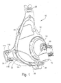
- FIGURE 1 is a perspective view from the front left side illustrating a first preferred embodiment of the present invention
- FIGURE 2 is a rear view thereof
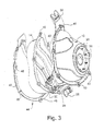
- FIGURE 3 is a front perspective exploded view of a portion of the assembly shown in FIGURE 1 ;
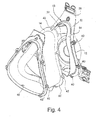
- FIGURE 4 is a rear perspective exploded view of a portion of the assembly shown in FIGURE 1 ;
- FIGURE 5 is a bottom view of the mask assembly shown in FIGURE 1 ;
- FIGURE 6 is a top view thereof
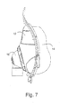
- FIGURE 7 is a right side view thereof
- FIGURE 8 is a perspective view of a frame according to an embodiment of the present invention.
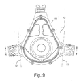
- FIGURE 9 is a rear view thereof
- FIGURE 10 is a top view thereof
- FIGURE 11 is a bottom view thereof
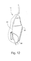
- FIGURE 12 is a side view thereof
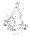
- FIGURE 12A is a perspective view of a frame according to another embodiment of the present invention.
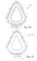
- FIGURE 13 is a front perspective view of a cushion according to the present invention.
- FIGURE 14 is a front view thereof
- FIGURE 15 is a rear view thereof
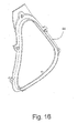
- FIGURE 16 is a rear perspective view of a cushion clip according to the present invention.
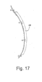
- FIGURE 17 is a side view thereof
- FIGURE 18 is a partial exploded cross-sectional view showing assembly of the frame, cushion and cushion clip
- FIGURE 19 is an assembled partial cross-sectional view thereof
- FIGURE 20 is a partial exploded cross-sectional perspective view like that shown in FIGURE 18 ;
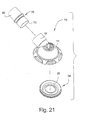
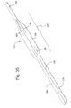
- FIGURE 21 is an exploded perspective view of a swivel elbow assembly according to the present invention.
- FIGURE 22 is an assembled view thereof
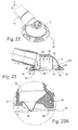
- FIGURE 23 is a cross-sectional view thereof
- FIGURE 23A is an enlarged detail view of a portion of FIGURE 23 ;
- FIGURE 23B is a perspective and cross-sectional view of an elbow according to an embodiment of the invention.
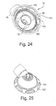
- FIGURE 24 is a rear perspective view of a swivel elbow according to an embodiment of the present invention.
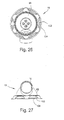
- FIGURE 25 is a front perspective view thereof
- FIGURE 26 is a rear view thereof
- FIGURE 27 is a bottom view thereof
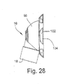
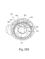
- FIGURE 28 is a side view thereof
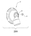
- FIGURE 28A illustrates a perspective view of a swivel elbow according to another embodiment of the present invention.
- FIGURES 28A-1-28A-2 illustrate views of an elbow according to still another embodiment of the present invention
- FIGURES 28B-28C illustrate views of an elbow according to an alternative embodiment of the present invention
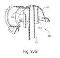
- FIGURES 28D-28H illustrate views of an elbow according to yet another embodiment of the present invention.
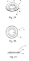
- FIGURE 29 is a front perspective view of an anti-asphyxia valve membrane according to the present invention.
- FIGURE 30 is a front view thereof
- FIGURE 31 is a side view thereof
- FIGURES 31-A to 31-I illustrate a mask assembly, elbow, swivel and/or anti-asphyxia valve member in accordance with an embodiment of the present invention
- FIGURE 32 is a front view of a headgear clip according to the present invention.
- FIGURE 33 is a perspective view thereof
- FIGURE 34 is a rear view thereof
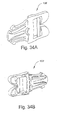
- FIGURE 34A and 34B illustrate front and rear perspective views of a headgear clip according to another embodiment of the present invention
- FIGURE 35 illustrates a perspective view of headgear according to one embodiment of the present invention
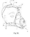
- FIGURE 36 is a front perspective view of the headgear of FIGURE 35 in position on a human head;
- FIGURE 37 is a rear perspective view of the headgear of FIGURE 35 on a human head;
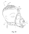
- FIGURE 39 illustrates the headgear of FIGURE 38 from front perspective view on a human head
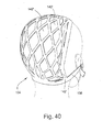
- FIGURE 40 illustrates the headgear of FIGURE 38 in rear perspective view on a human head
- FIGURE 41 illustrates a perspective view of headgear according to still another embodiment of the present invention.
- FIGURE 42 is a perspective view of the headgear of FIGURE 41 on a model patient's head.
- Figure 1 shows a mask assembly 10 which includes a frame 12 in the form of a shell, and a cushion 14 that is provided, e.g., attached, to the frame 12.
- a swivel elbow 16 is rotatably coupled or provided to the frame 12.
- the swivel elbow 16 includes an inlet conduit 18 that receives pressurized breathable gas from a suitable source of pressurized air, as is known in the art.
- the swivel elbow 16 includes one or more apertures 20 which serve to continually wash out exhaled CO 2 gas from a breathing chamber formed by the frame 12 and the cushion 14.
- the frame 12 includes at least a pair of lateral outriggers 22 which support connector clip receptacles 24 designed to receive connector clips (see, e.g., Figures 32-34 ) associated with headgear (see, e.g., Figures 35-40 ).
- the frame 12 includes a centrally located upper extension 38 including various structure intended to interlock with a headgear strap of headgear.
- Frame 12 also includes at least one port 26 that allows for the introduction of a pressure monitoring probe, or a separate gas such as oxygen (O 2 ) to be introduced (via a tube) into the interior of the breathing chamber.
- the port 26 may be suitably covered by a port cap 28 which is shown in the disconnected position in Figure 1 . As described and shown below, the port cap 28 may be formed as an integral part of the cushion 14.
- Figure 2 illustrates a patient's side or rear view of the mask assembly 10.
- the face contacting portion of the cushion 14 preferably includes a double layer, spaced wall configuration as described in U.S. Patent No. 6,513,526 assigned to ResMed Limited and incorporated herein by reference in its entirety.
- other cushion configurations such as single or triple layer cushion configurations could also be employed without departing from the spirit and scope of the present invention,
- the cushion can be made of silicone, foam, gel, etc., or combinations thereof.
- Figure 2 also illustrates an aperture 30 which communicates the inlet conduit 18 of swivel elbow 16 to the breathing chamber.
- Surrounding aperture 30 is a generally circular support 32 formed as part of the frame 12.
- the support 32 forms a surface for an anti-asphyxia valve membrane 34 (shown in detail in Figures 29-31 ).
- the anti-asphyxia valve membrane 34 is positioned between the support 32 and the swivel elbow 16.
- Figures 3 and 4 illustrate front and rear exploded views of the mask assembly 10 shown in Figure 1 , without the swivel elbow 16 or its associated anti-asphyxia valve membrane 34. As shown in Figure 3 , the anti-asphyxia valve membrane 34 would be positioned adjacent circular support surface 36 of frame 12.
- Frame 12 includes at least one and preferably a plurality of through holes 40 which are intended to align with complimentary through holes 42 provided on cushion 14.
- the cushion 14 is intended to be sandwiched between frame 12 and a cushion clip 44.
- the cushion clip 44 includes a corresponding number of fasteners or rods 46, e.g., provided along a flanged perimeter portion 48 of the cushion clip 44.
- the rods 46 are intended to align with and pass through the holes 42 and 40 of the cushion 14 and frame 12, respectively. Tips of rods 46 may be snap-fitted, melted or ultrasonically deformed so as to lock with respect to apertures 40, thereby effectively sandwiching the cushion 14 in place between the frame 12 and the cushion clip 44.
- Rods 46 may include enlarged head portions that are tapered to allow penetration through holes 40, 42 for assembly purposes. However, enlarged heads help prevent disassembly of the frame, clip and cushion. Therefore, the cushion 14 may be permanently sandwiched in place, i.e., it is difficult to disassemble, which may be a benefit in a hospital or clinical environment. However, the cushion could be structured to allow for selective disassembly, if desired.
- the cushion 14 includes a lateral perimeter flange 50 which may also be sandwiched or clamped between the frame 12 and the cushion clip 44. Figure 3 also shows that the flange 50 may provide a support surface for integral connection with port cap 28 via bridge 29.
- the frame may be provided with the rods, and the cushion clip could be provided with holes.
- Figure 4 best shows an inside surface 52 of the frame 12.
- an upstanding wall member 54 which preferably extends along the entire perimeter to define the opening of the frame 12.
- the wall 54 provides support for the side walls of the cushion 14 as well as the interior side walls of cushion clip 44.
- Figures 5-7 illustrate further assembly views of the frame 12, cushion 14 and swivel elbow 16.
- Figures 8-12 illustrate further views of the frame 12 in isolation.
- the frame 12 includes a notch 56 provided to facilitate passage of bridge 29 (see Figures 3 , 14 and 15 ) from the cushion side to the frame side.
- the frame 12 also includes a plurality of protrusions or castellations 60, e.g., 8 castellations, for the purposes of assisting with retention of anti-asphyxia valve membrane 34 in elbow assembly (see Figures 22, 23 and 29 ).
- the frame 12 includes a perimeter flange 64 which defines a groove 66 by which the swivel elbow 16 is secured to the frame 12.
- Figure 8 shows that the outrigger 22 includes legs 68, each of which includes a first end attached or otherwise provided to main portion of the frame 12, and a second end attached to or otherwise provided to the connector clip receptacle 24.
- the outriggers are formed as an integral piece with frame 12 and outrigger 24.
- the outriggers 22, e.g., legs 68 may bend, and/or flex about an axis 72, as indicated in Figures 8 and 9 .
- Legs 68 can also be structured so as to pivot in a hinge-like manner. The provision of this type of movement allows for certain benefits, e.g., headgear strap self-tensioning and/or age/usage indication, more fully described below.
- Figures 10-12 show top, bottom and side views of the frame 12, respectively.
- Figures 10 and 11 have bidirectional arrows which schematically indicate the bending, pivoting and/or flexing of legs 68 about axis 72.
- Figure 12A illustrates a perspective view of an alternative embodiment of a flame 12'.
- the frame in Figure 12A is very similar to the frame shown in Figure 8 , the only main difference being that frame 12' includes 16 instead of 8 castellations 60.
- the increased number of castellations helps to reduce leak between the elbows and anti-asphyxia valve membrane.
- the number of castellations may vary, and may, for example, include any number above or below 16.
- one or both ends of legs 68 may include a portion 70 about which the arm may pivot, bend and/or flex. This would allow the mask to assume various configurations, e.g., by moving the outrigger vertically up or down with respect to the main body of the frame, as schematically illustrated by arrows in Figure 9 .
- the legs 68 should be parallel to one another to allow this adjustment, even though the legs are seen as non-parallel (i.e., trapezoidal) in Figures 8 and 9 .
- Figures 13 through 15 illustrate various views of the cushion 14 in isolation
- Figures 16 and 17 illustrate various views of the cushion clip 44 in isolation.
- Figure 18 illustrates a partial cross-sectional and exploded view to highlight the connection between frame 12, cushion 14, and cushion clip 44.
- Figure 19 is an assembled view of the components illustrated in Figure 18
- Figure 20 is a perspective version of the exploded view shown in Figure 18 .
- frame 12 includes a bead-like member 13, which helps to establish and ensure a reliable seal between frame 12 and cushion 14.
- Figure 19 shows bead member 13 embedded within cushion 14, although cushion 14 could also include a groove or aperture to receive bead member 13.
- Bead member 13 can also be seen in Figure 4 .
- FIG. 21 illustrates an exploded view of a swivel elbow assembly 73, including swivel elbow 16, anti-asphyxia valve membrane 34 and swivel joint 76.
- Swivel joint 76 includes first end 78 provided to inlet conduit 18 and second end 80 provided to an air delivery tube in communication with a source of pressurized breathable gas.
- Figure 22 illustrates an assembled view of the components shown in Figure 21
- Figure 23 shows a cross-sectional view of the assembled swivel elbow assembly.
- the anti-asphyxia valve membrane 34 is preferably made of an elastomeric material.
- the swivel elbow 16 includes a generally cylindrical inner tube 82.
- the cylindrical tube 82 may provide a baffle between incoming air delivered via swivel joint 76 and vented air, as indicated by the directional arrows in Figure 23.
- Figure 23 A shows an enlarged detailed view of a portion of the assembly shown in Figure 23
- Figure 23B is a partial cross-sectional view illustrating the elbow as connected to frame with member 34 in position.
- the anti-asphyxia valve membrane 34 includes a main body 84 which seals and/or interlocks, e.g., via friction, with upstanding wall member 86 formed as part of swivel elbow 16.
- Anti-asphyxia valve membrane 34 also includes an aperture 88 ( Figure 21 ) which includes an inner shoulder 90 ( Figure 23 ) for sealing against the outer surface of cylindrical tube 82 of swivel elbow 16.
- the anti-asphyxia valve membrane 34 includes an outer shoulder 94 that prevents over-insertion of the membrane 34 within the swivel elbow 16 and allows for a snug fit with upstanding wall member 86 of swivel elbow 16.
- Figure 24 illustrates a perspective view of swivel elbow 16 as seen from the patient's side. Air is delivered via inlet conduit 18 into dome portion 98 of swivel elbow 16.
- the swivel elbow includes a plurality of friction enhancing members 100 designed to ensure that the anti-asphyxia valve membrane 34 stays frictionally engaged with the swivel elbow 16.
- the swivel elbow 16 also includes a plurality of slots or apertures 102 adjacent to which a plurality of tab members 104 are positioned, as seen in Figures 24 and 25 .
- the tab members 104 are inclined ( Figure 24 ) so that they slightly expand or cam-out upon engaging flange 64 as shown in Figure 12 , until overcoming the flange 64 and seating the tab members 104 within groove or undercut 66, at which point the parts snap-fit to establish a connection.
- apertures 102 helps to weaken the swivel elbow 16 such that upon an attempt to disassemble the swivel elbow from the mask, the portion supporting the tab members or the tab members themselves deform and/or break away from the swivel elbow 16, thereby rendering the mask unusable, in which case a new mask would be required for the patient.
- the selective weakening does not adversely impact the performance of the mask.
- Apertures 102 may also act as windows for breathing to atmosphere when the anti-asphyxia valve member is de-activated.
- Figures 26 through 28 illustrate various views of the swivel elbow 16 in isolation
- Figures 29 through 31 illustrate various views of the anti-asphyxia valve member 34 in isolation.
- Figure 28A illustrates another embodiment of the invention, including a swivel elbow 16' which is similar to elbow 16 shown in Figure 22 .
- elbow 16' includes a single aperture 20' provided for washout of exhaled CO 2 gas.
- Aperture 20' may be fitted with a duck bill valve 23, which is known in the art.
- Figures 28A-1 and 28A-2 illustrate an elbow according to a slight modification, in which the aperture 20" is raised and a valve member 23' is attached thereto.
- members 23, 23' constitute valve members.
- members 23, 23' could constitute plugs that selectively seal the aperture. When the plug is in place, the aperture is sealed and the elbow is non-vented. When the plug is removed, the aperture is exposed, thereby serving as an access port to receive a tube, e.g., naso-gastric in nature.
- FIGS 28B and 28C illustrate a swivel elbow 200 according to yet another embodiment of the present invention.
- Elbow 200 is intended to include an anti-asphyxia valve membrane (not shown) as described above.
- elbow 200 includes a dome portion 202 and a cylindrical center tube member 204. Upstanding wall 206 and tube member 204 are structured to support anti-asphyxia valve member. Dome is provided with a plurality of slots or apertures 208 and tab members 209, each of which function as described herein.
- a tube 210 having a first end 212 that extends through central aperture of anti-asphyxia valve membrane.
- Tube 210 includes a second end (not visible) which is integrally connected or provided to the peak of dome 202.
- dome will include only a single aperture, like that shown in Figure 28A .
- tube member 204 includes an aperture 214 which is provided at a base of tube member 204.
- Aperture 214 in this example is eye-shaped, although it could have any shape.
- FIGS 28D-28H illustrate an elbow 300 according to another embodiment of the present invention, which is similar to the embodiment of Figures 28B and 28C .
- dome portion 302 includes a plurality of concentric, raised rings 303.
- center tube portion 304 extends just outside dome portion 302, but ends before reaching the lower end of the elbow housing which helps with CO 2 gas washout.
- An inner tube 310 extends from the top of the dome portion 302 and past the end of the elbow housing.
- the top 311 of the inner tube 310 is profiled, as shown in Figures 28E-28G .
- the opening 313 leading to atmosphere is of smaller cross-section than the central portion 315 of tube 310.
- a transition 317 is formed between the opening 313 and central portion 315.
- Transition e.g., may take the form of a tapered conical section.
- central tube 302 includes an aperture 314 to allow the flow of gas from the air delivery conduit to the inside of tube 302, which helps to lower impedance.
- Figures 31-A to 31-I illustrate a mask assembly 10 according to another embodiment of the present invention.
- Figure 31-A is a front view of the mask assembly 10
- Figure 31-B is a side view of mask assembly 10.
- the illustrated reference numbers denote components or parts that have been described in relation to one or more embodiments described above, e.g., Figure 1 .
- Mask assembly 10 includes a swivel elbow 16' that is more specifically discussed in relation to Figures 31-C - 31-F .
- Elbow 16' includes an inlet conduit 18 ( Figure 31F ) having a hose end 18a with a plurality of resiliently deformable tabs 18b that are structured to allow selective attachment to and detachment from a swivel 76.
- Each tab 18b includes a radially extending protrusion 18c that locks in place within an interior of groove 76a of swivel 76.
- Figure 31-E shows the assembled position.
- the elbow 16 is preferably made from a polyester, e.g., natural POCAN®, a Bayer product, although other materials are possible.
- the swivel 76 may be made of clear polycarbonate, although other materials are possible. This assembly allows for removal of the hose (not shown) without compromising the integrity of the frame.
- the internal geometry and functioning of the dome portion of elbow 16' is similar to or the same as that described above or in relation to Figures 28D-28H .
- Elbow 16' may be used in conjunction with anti-asphyxia valve member 34', as shown in Figures 31-G to 31-I , whose function is similar to the member 34 described in relation to Figures 29-31 .
- FIG 32 illustrates a headgear clip 106 according to one embodiment of the present invention.
- the headgear clip 106 includes a first end 108 for engagement with headgear clip receptacle 24 shown in Figures 1 and 2 and a second end 110 for engagement with a headgear strap of headgear assembly.
- the first end 108 includes first and second arms 112 which may be flexed toward one another in the plane of the paper so as to squeeze into receptacle 24.
- the receptacle 24 includes an appropriate protrusion or catch 114 ( Figure 1 ) in a locked position.
- each receptacle 24 includes a pair of opposed arm members 116 which may be pressed toward one another to thereby compress the arms 112 towards one another, thereby placing the headgear clip 106 in a position such that it can be removed from the outrigger 22 and the receptacle 24.
- the geometry of clips 106 allows them to spring out of receptacles 24 when opposing arms 116 of receptacle are pressed.
- Each headgear clip 106 includes a central leg 118 including a groove 120 which is designed to receive a protrusion 122, shown in Figure 2 .
- Figure 33 is a front perspective view of the headgear clip 106, while Figure 34 is a rear view of the headgear clip 106.
- different headgear clip and clip receptacles can be used instead.
- Figures 34A and 34B illustrate another embodiment of a headgear clip 106' which is similar to the clip 106 shown in Figures 32-34 .
- Several changes have been made which may reduce manufacturing costs, facilitate manufacture, and/or enhance performance.
- Figure 35 illustrates a first embodiment of headgear 124 according to the present invention.
- Headgear 124 may be manufactured by starting with a substantially flat piece of appropriate material, such as polyester loop material, Breathoprene®, leather, cloth, plastic, etc., and then cutting, scoring or weakening the headgear along predetermined cut lines 126 whereby the headgear 124 may be repositioned to approximate the shape of the patient's head.
- the headgear 124 may include side straps 128 and front strap 130. Side straps 28 may be created with a single slit 126.
- main body 127 of strap has an appropriate amount of slits, e.g., 2-5 slits or more, to optimize coverage and stability of the headgear 124 or patient's head.
- slits 126 expand in use to form a plurality of open spaces 126', when the headgear is placed on the patient's head.
- FIG. 36 The positioning of the headgear 124, including the side straps 128 and front strap 130, in relation to the mask assembly 10 and the patient's head is shown in Figure 36 .
- Figure 37 illustrates a rear perspective view of the patient's head with the headgear 124 provided thereto. This position cups the occiput of the head to thereby create stability.
- the headgear includes a plurality of fold lines 132 which are created due to repositioning of the headgear 124 from the position shown in Figure 35 to the position shown in Figures 36 and 37 . These predetermine fold lines 132 are acceptable for use in a clinical or hospital environment. However, they do not adversely affect the performance of the headgear 124.
- Figure 38 illustrates a second embodiment of headgear 134 according to the present invention.
- Headgear 134 includes side straps 136 and front strap 138.
- the headgear 134 may be manufactured by providing a flat piece of material appropriate for use as headgear on a patient
- Each side strap 136 is created by cutting the material along a predetermined cut line 140.
- the headgear 134 may include a plurality of additional cut lines 142, which creates a net-like configuration on the patient's head, as shown in Figures 39 and 40 .
- Each cut line 142 forms an open area 142', to effectively cup the patient's head.
- Open areas 142' provide for ventilation of the patient's head.
- Open areas 142' may be in the shape of a polygon, e.g., a triangle or a diamond. Of course, other headgear arrangement may also be used to support mask assembly on the patient's head.
- Figure 41 illustrates headgear 400 according to another embodiment of the present invention.
- Headgear includes side straps 402, 404 and a top strap 406, such that it can be used with the mask shown in Figure 1 .
- Headgear 400 includes cutouts 408 which help with ventilation and ensure that the headgear is fully retained. Cutouts 408 help headgear to conform to the patient's head.
- Headgear 400 includes a unidirectional stretch back piece 410. Cutouts 408 may be separated by a divider 409 which may be detachably connected, e.g., via stitching and/or Velcro®, etc.
- Figure 42 shows the headgear in position on a model patient's head.
- the mask assembly 10 is intended to be used by a single patient for a limited life span and not reused on further patients. This removes the time and expense of cleaning and reassembling the product. In addition, it removes the difficulties found when components can be lost or assembled incorrectly. For safety reasons, and to avoid cross-infection, the product should have both the function and/or aesthetics of a disposable product in order to alert the user and discourage extended use or use on more than one patient.
- the mask assembly has been configured so as to satisfy needs of a clinical or hospital staff. This has been achieved while retaining mask performance desired by patients, which performance includes comfort, minimized leaks, etc., and therefore facilitates patient compliance with treatment.
- the mask appears to be disposable from the feeling that it is less durable than a reusable mask.
- the mask is purposely prone to distortion through handling because it is made from materials that have an expected service life, e.g., of about 7-14 days, and preferably no more than 7 days.
- the mask has the characteristic of displaying its "age", e.g., via stress whitening (described in more detail below), and therefore provides an indication to users of the mask system's aging and approaching end-of-life. This aging characteristic is in contrast to prior art disposable masks that typically, without warning, fail in use, for example, when they are stressed while undergoing the procedures of disassembly, washing, assembly or fitting.
- the mask system provides a warning to users of approaching end-of-life.
- the aging characteristic is intended to serve the safety function of dissuading cross-patient use - the second intended user is disinclined to select or don a used mask. In this way, the aging characteristic facilitates the control of cross-infection and is therefore particularly useful in a clinical multi-patient environment.
- the frame may be formed by polypropylene, polyethylene, PETE, etc., and may be manufactured using a molding process, e.g., injection molding.
- the frame is made of polypropylene with a thin walled section (approximately 0.25-1mm, preferably about 0.5 mm) that gives it the characteristic of being more flexible than typical multi-use mask frames. Flexibility is desirable because it gives the feeling of being less durable.
- stress whitening occurs as a result of excessive or repeated deformation of polypropylene and other materials such as polyethylene or PETE. Such excessive and/or repeated deformation will eventually cause the frame material to turn white, ergo the term "stress whitening.”
- the present embodiment incorporates the characteristic to display stress whitening through an appropriate combination of design and/or components.
- the wall thickness and stress loading can be designed so as to control stress whitening to occur in those portions of the mask which are most visible to the clinician.
- the outriggers 22, e.g., legs 68, shown in Figure 8 maybe designed such that they will deform when the headgear is fitted and as such they will exhibit stress whitening with use.
- the outriggers 22 include legs 68 which are intended to bend, flex or pivot about axis 72, as shown in Figures 8 and 9 . Repeated and/or excessive such movement can cause stress whitening.
- stress whitening can be used to form a readable text message (e.g., "replace mask” or "discard") which appears only after stress whitening has occurred.
- the mask could be designed such that stress whitening occurs in other locations.
- Stress whitening will give the visual indication that the mask system has been used. If the mask frame is configured so that the development of stress whitening (e.g., increase in intensity or area displaying stress whitening, or both) occurs as a result of repeated deformation during use, then the mask will also provide a visual indication of aging and approaching end-of-life.
- stress whitening e.g., increase in intensity or area displaying stress whitening, or both
- the mask may exhibit some degree of stress whitening, stress whitening alone will not cause breakage, thereby causing a catastrophic failure.
- stress whitening alone will not cause breakage, thereby causing a catastrophic failure.
- the state of the prior art is that masks exhibit a tendency toward unexpected catastrophic failure, e.g., a component snapping, without warning.
- a complimentary but independent feature further enhances the frame's disposable characteristic.
- Some and preferably all components are configured to assemble with a one-way snap action. Once the mask frame/vent and anti-asphyxia valve and cushion components are assembled, they cannot be disassembled without breakage occurring. Further, disposable characteristics of a mask system are that the mask cannot effectively be cleaned as it cannot be disassembled which is a further indication that it is disposable, it is low cost, it has white headgear that is likely to show dirt, grime and wear, and/or it is appropriately labeled.
- the frame may include a headgear strap with a self-tensioning feature. This will facilitate a clinical party (i.e., non-patient) fitting of the mask without assistance of the patient.
- the flexible legs 68 that extend from the frame include attachment points for the lower two headgear straps. The flexibility allows for the legs to fold towards the back of the patient's head and thereby provide extra length to the headgear straps/flexible arms combination when fitting the mask system, thus allowing for the headgear to be located over the patient's head. Then, when the mask and headgear are in place, the legs spring forward, i.e., away from the patient's face, thereby placing some tension to the headgear mask assembly. This helps to avoid the need for cooperation of the patient.
- the cushion 14 disclosed herein may adopt at least some of the same geometry as is available in the current Mirage® Full Face mask, which includes an upper membrane and an underlying profile. See U.S. Patent No. 6,513,526 incorporated herein by reference in its entirety.
- the cushion 14 is attached to the frame 12 by sandwiching the cushion between the cushion clip 44 and the frame 12.
- the cushion 14 may be attached to the frame 12 using mechanical (e.g., tongue and groove) and/or adhesive techniques.
- the cushion can be molded directly to the frame, e.g., via over-molding, with the frame being made of polypropylene and the cushion being made of TPE.
- the anti-asphyxia valve situated in the swivel elbow 16 functions as both an anti-asphyxia valve and a back flow reduction device.
- the valve is permanently assembled from three components - the elbow, the valve membrane 34 and the frame 12.
- the membrane 34 is an interference fit with the elbow 16 (see, e.g., Figures 23, 23A , 23B ) which is then a permanent snap fit to the frame 12.
- the snap fit includes an undercut on the frame, e.g., groove 66 in Figure 12 , which connects with six tab members 104, for example, on the elbow 16.
- valve membrane 34 When the flow generator is switched off, or in the case of malfunction such as a power cut, the valve membrane 34 sits in the original or unextended position. The edge of the membrane forms a seal against the inner tube 82 of the elbow 16 and thus prevents flow from the mask reaching the inlet conduit 18 and consequently the flow generator. Thus, the valve prevents gas flow back to the flow generator which is particularly useful in circumstances where O 2 is ported into the mask. Any O 2 that is supplied to the mask cannot reach the flow generator, i.e., the valve acts as an O 2 divertor valve (ODV) and removes a potential fire hazard.
- O 2 divertor valve O 2 divertor valve
- the membrane 34 When the flow generator is switched on and pressure is applied, the membrane 34 extends from its original position and forms a seal against the circular inlet (e.g., surface 36 in Figure 3 ) of the frame 12.
- This pressurized air from the inlet conduit 18 can flow around the elbow inner tube 82 and directly through the circular inlet of the frame.
- the inner shoulder 90 may separate from the end of tube 82, as shown in phantom in Figure 23A .
- the valve member In this position, the valve member is configured such that it may provide an audible noise, e.g., a whistle. This may provide comfort or a positive feedback signal to the patient/clinician that the device is assembled properly and/or that pressurized gas is being properly channeled.
- the audible signal e.g., whistle
- the audible signal can be created by vibrations in a manner similar to that created when playing the reed of a musical instrument.
- a small gap may be designed to create the whistle effect.
- the device e.g., the anti-asphyxia valve, may be arranged such that a noise is created if the system is not correctly assembled, to thereby provide a warning to the user or clinician.
- the mask can be designed to include or not include noise, depending on preference.
- This design achieves a lower profile elbow, which is desirable both for aesthetic reasons and it improves the stability of the mask. Another factor to consider when designing the elbow is the entry impedance of the mask. It is desirable to minimize impedance in order to prevent pressure swings occurring during breaths.
- the lower profile elbow is achieved by a number of factors. Firstly, the elbow acts as the housing for the membrane and the valve is placed at the interface of the elbow in the frame. This reduces the number of components that are required (and associated manufacturing costs) as well as removing the bulk of a further interface. Secondly, the inlet conduit 18 is at an angle from the mask of greater than 90°, e.g., 100°-120°. Thirdly, the diameter of the inlet cavity has been increased. This increases the cross-sectional area presented to the inlet flow (and thus reduces the entry impedance) for a given elbow inlet angle.
- the valve is physically larger than the existing ResMed anti-asphyxia valve mentioned above to achieve a reduced impedance in the elbow compared to the currently available ODV.
- the mask vent is incorporated in the elbow.
- Existing ResMed full face masks have their vents incorporated in the mask frame.
- Inadvertent leak is virtually zero due to the configuration of the vent and anti-asphyxia valve.
- This performance is achieved partly by configuring the anti-asphyxia valve to include a relatively soft part, e.g., membrane 34 made, e.g., of silicone, to seal between the frame and the swivel elbow.
- vent in the elbow By putting the vent in the elbow it is relatively easy to block the orifice joining the mask chamber and the elbow downstream of the vent so as to achieve the required isolation.
- This configuration avoids the difficult to perform blocking of the large path to atmosphere that occurs at the mask aperture, i.e., the mask chamber entry point which receives the patient's face.
- a plug may be used to block the orifice between the elbow and the mask chamber, but it may be also easily achieved in the clinical setting by placing a finger over the orifice.
- This embodiment of the invention simply has a single elbow to calibrate for flow, independent of the mask frame size.
- the anti-asphyxia valve may be adopted for use in a multiple use full face mask as it is made from silicone where it will be robust, washable and capable of reassembly.
- the anti-asphyxia valve is then a common part, requiring less inventory and there will be no need to develop a new anti-asphyxia valve for a new face mask.
- the frame port cap is configured to meet clinical needs.
- the port cap is integrated into the cushion configuration, which allows the port cap to be formed at the time of cushion manufacture, thereby eliminating the need for separate manufacturing. This allows for a one molding operation to make the cushion and mask components. It also allows the port cap to pass through manufacturing and distribution chain as one component with the cushion. This simplifies handling and inventory logistics, and reduces manufacturing and warehousing costs.
- the location of the port cap in relation to the cushion are such that when the cushion is attached to the frame, the port cap is conveniently positioned to be attached to the frame port.
- the port cap has one or more large grip wings to facilitate convenient manipulation.
- a problem identified by the inventors is that the typical small port caps supplied with prior art masks are an annoyance to the regular clinical user. Grip wings may be supplied for a group of port caps or individually associated with each port cap.
- the port and port cap are located at the bottom of the mask so as to avoid interference with other components of the mask assembly, as described in U.S. Patent No. 6,439,230 , assigned to ResMed Limited and incorporated herein by reference in its entirety.
- the port and port cap could be located in other convenient positions around the mask frame.
- multiple ports and caps could be provided to the same mask.
- the headgear performs in a manner that contributes to the systems aging characteristic. This performance is achieved by use of material that gives a display of its accumulation of grime, i.e., soiling.
- the chosen material accumulates and displays its accumulation of grime, e.g., by visual and tactile signals.
- the headgear when first brought into service is generally white or other a light shade of color.
- the aging characteristic achieved through the perception of soiling will provide a useful psychological signal. Potential users will not want to don a seriously soiled headgear while a clinical staff will be prompted to choose a fresh mask system for patients especially when fitting a patient new to the mask.
- Grime may be attributable to skin, sweat, oils, facial secretions, etc.
- the aging characteristic may be incorporated into the headgear and/or mask frame in such a way that the headgear or mask frame exhibits age due to exposure with such sources of grime.
- grime may provide a visual indication on the headgear frame to signal the clinician that it is time to replace the mask system.
- the aging characteristic can be provided with headgear which frays or otherwise decomposes after repeated use beyond the nominal set limits.
- the headgear strap configurations allow for more consistent location of straps under the patient's ear and thereby avoid the annoying contact of the strap with the lower portion of ear.
- Headgear may be configured from a die cut side piece, e.g., a laminated material which in its unassembled form is shaped to minimize waste and thus reduce costs/control.
- the waffle pattern when expanded, will allow for expansion and correct placement on the head.
- This design achieves a three-point fitting configuration.
- a two-dimensional piece of material is used to achieve a three-point headgear which achieves the performance of a four or five-point headgear. This allows for placement of the top strap to follow a line which is low on the ears and resembles what is achievable with a four strap headgear, which allows for desirable distribution of forces but with the convenience of one top strap.
- the headgear clip mechanism includes a housing which incorporates release tabs and that is formed as part of the frame.
- a headgear clip is spring-fit into the receptacle on one side and acts as an attachment point for the headgear on the other side.
- the headgear attachment side has two slots.
- the first slot 111 ( Figures 32-34 ), closest to the mask, is a fully formed slot through which the headgear is threaded.
- the second slot 113 closest to the headgear has large shaped tabs 115 formed on one side, between which a gap G exists.
- the gap G and the tapered shape of the tabs allows the headgear to be connected through the second slot by pulling down through the tabs. This assembly technique is much simpler than threading.
- the clip is very large which makes it easier for manipulation.
- the tabs 116 ( Figure 1 ) to release the clip are operated from the top and bottom which facilitates the user configuration. Further, the tabs 116 form part of the frame, rather than part of the clip. Therefore, the tabs do not slide with the clip which makes single handed operation easier.
- the headgear clip may include a ladder lock and lead-in design.
- the headgear clip may serve as a quick release mechanism, i.e., the sprung release of the clip is a quick release mechanism. It has an exaggerated tactile finger tab to make it easier to find should there be a need for rapid response quick release.
- the headgear clip allows for quick manual assembly which serves both as a manufacturing aid and a benefit to customers as it allows for a presentation of a fully assembled product and benefits a clinical setting as it allows for quick reassembly when required.
- Hospital and fully featured hospital use is characterized by several factors: single patient use, clinician requirements, and/or a desirability to discourage reuse.
- Ease of fitting may be achieved via a headgear spring/outrigger design.
- Ease of assembly prevents incorrect assembly and protects from interference and tampering. Disassembly is prevented between the cushion and frame since they are permanently connected.
- the elbow is snapped to the frame via a one-way snap, which cannot be disconnected without destroying or breaking the elbow and/or frame.
- the ports cap is formed as an integral portion of the cushion, thereby preventing its loss or detachment.
- the mask is designed to discourage reuse because there is no method of efficient cleaning that is possible as there is no access to the anti-asphyxia valve.
- the mask displays evidence of use, e.g., via stress whitening and distortion under force.
- Stress whitening may be achieved by some combination of material, wall section dimensions, geometric form and/or use of a yielding flexible part.
- the materials may include polypropylene, polyethylene or PETE, and may be made by molding, such as injection molding or they may be vacuum formed.
- the stress whitening may be provided via the outriggers although the top support of the frame, the forehead support, port cap, etc. may also be used to exhibit stress whitening.
- a living hinge could also be used to display evidence of use.
- stress whitening include snapping via a one-way connection, to thereby prevent or inhibit reuse.
- Other possible indicators include exposure to air, O 2 or grime, exposure to condensation (moisture indicators), CO 2 detectors, etc.
- the mask frame is intended to look disposable and non-durable via one or more of the following criteria: material choice, color (headgear is white, frame could also be white). Headgear could be cardboard with a plastic interior, material thickness, simple construction and/or an exposed construction method.
- the mask feels disposable, e.g., the frame is flexible and will deform with predetermined and/or repeated application of force.
- the port and cap structure is advantageous since it is an integral component with the cushion, and cannot come apart from the assembly. Therefore, the port cap cannot be lost since it is attached to the cushion. This allows for lower manufacturing cost as the cushion and cap are one component rather than two. This also prevents cross-patient use.
- the port cap includes one or more large grip tabs, which are easier to operate, particularly for clinicians.
- the large grip tabs allow for easy location.
- the grip tabs are visible, and show whether they are on or off, and their operation is obvious to inexperienced users, thereby avoiding the error of cap being left off.
- the port cap is self-locating, meaning that the cap stays close to the port when removed, but requires little dexterity to place the port cap back onto the port, and does not require visual affirmation since affirmation can be provided via tactile means.
- the port cap is positioned at the bottom of the frame, which is near the nares, thereby providing an advantage for the supply of oxygen.
- the port cap is not susceptible to being disturbed by movement of the patient's head.
- the port cap allows an air inlet tube and swivel to rotate freely. The most common position of the air inlet tube is always away from the bottom, and the smaller tubes can be easily routed along the tube as commonly occurs.
- Alternative embodiments include a living hinge cap molded from the frame. This had the advantage of displaying evidence of use, e.g., stress whitening.
- a barbed head may be pulled through the frame or cushion wall, with the barbed head sealing against the frame.
- the port cap can be molded with a thin strap directly to either the cushion or the frame.
- the port cap may be sandwiched between the cushion and frame, which decreases the chances that the port cap can be lost.
- the port cap can be co-molded with the frame.
- the port cap can be molded integrally with the anti-asphyxia valve or the vent or any elastomeric component.
- the port cap can be purposely made to break off with use to display hospital use, to thereby convey the disposable nature of the mask. Alternatively, the port cap may develop a cut end with overuse.
- the above described self-tensioning feature facilitates fitting of the mask assembly to the patient.
- the self-tensioning spring provides elasticity when required, e.g., when initially taking the headgear over the head. This allows a larger degree of opening when fitting.
- it could be used with non-elastic headgear, and is particularly suitable for a third party/clinician fitting.
- the self-tensioning aspect provides a spring to give some tension when initially fitted before tightening the straps. This prevents the straps from simply flopping and prevents the tangling of straps.
- the self-tensioning aspect provides a visual indication that straps are not tight or tensioned.
- a tension indicator may be provided, which displays the amount of tension either by angle (this could be whilst on the patient) or with permanent deformation for clinical evaluation after patient use.
- the self-tensioning aspect keeps the headgear from tangling away from the patient, and may include broad attachment points, which maintain strap alignment and does not twist.
- the self-tensioning aspect also may display evidence of use, e.g., via stress whitening upon use. Evidence of use may also be demonstrated via use of various combinations of material, thickness and geometric form.
- the outriggers may also creep with use to a point at which it does not regain form after patient use.
- the outriggers could be used on reusable masks.
- the headgear clips can be snapped into use under certain tension. This has an advantage of maintaining form and a larger degree of opening but does not act as a spring. This may give a strong indication of use by not maintaining form after first use, and encourage the product to be thrown away after single patient use.
- the outrigger assembly may include a living hinge, which may be advantageous from the aspect of keeping form in larger degree of opening but does not act as a spring. This would give a strong indication of use by not keeping form after first use, and encourage the product to be thrown away after single patient use. This would show use at the hinge point.
- a self-tensioning spring could be attached to headgear rather than the frame.
- a tension indicator may display the amount of tension either by angle, whilst on the patient, or with permanent deformation for clinical evaluation after patient use.
- the hinge could be part of a cushion or a captive part of the cushion frame interface rather than part of the frame. The hinge could be incorporated into the designs of other existing disposable and reusable masks.
- Headgear according to the present embodiments include several features and/or advantages.
- the headgear is manufactured using a strip design, which is the lowest volume for manufacture, meaning low wasted or inefficient use of materials.
- the design expands from a one-dimensional strip in manufacture to a three-dimensional cup in use.
- the process for making the headgear can be from a single stamp or slit within the perimeter of the strip.
- the headgear need not cover much of the head, is cool and is unobtrusive.
- the headgear achieves a simple yet stable design. Different colors can be provided on each side of the material for a visual clue as to the part which is facing towards and away from the patient, which allows for ease of assembly and non-tangling of the strap components.
- Alternative materials for the headgear include foam, silicone and/or breathable materials.
- the material can be elastic or non-elastic, of varying stiffnesses in different directions. Further, separate strips can be joined with varying stiffnesses. This will allow fine tuning of the elasticity of individual straps of the headgear.
- Various stiffnesses can also be achieved by sticking VELCRO® tapes over part of the headgear or by providing cross-stitching, etc.
- the headgear can also be manufactured by forming a number of individual components, laying them next to each other and then joining them via stitching, gluing, etc.
Landscapes
- Health & Medical Sciences (AREA)
- Pulmonology (AREA)
- Life Sciences & Earth Sciences (AREA)
- Animal Behavior & Ethology (AREA)
- Anesthesiology (AREA)
- Biomedical Technology (AREA)
- Heart & Thoracic Surgery (AREA)
- Hematology (AREA)
- Emergency Medicine (AREA)
- Engineering & Computer Science (AREA)
- General Health & Medical Sciences (AREA)
- Public Health (AREA)
- Veterinary Medicine (AREA)
- Respiratory Apparatuses And Protective Means (AREA)
- Acyclic And Carbocyclic Compounds In Medicinal Compositions (AREA)
- Measuring Pulse, Heart Rate, Blood Pressure Or Blood Flow (AREA)
- Pharmaceuticals Containing Other Organic And Inorganic Compounds (AREA)
Abstract
Description
- This application claims the benefit of
U.S. Provisional Application Nos. 60/533,229, filed December 31, 2003 60/571,488, filed May 17, 2004 6/315,8,341, filed July 16, 2004 60/619,022, filed October 18, 2004 - The present invention relates to a disposable mask system for use with patients, e.g., adult patients, for the treatment of obstructive sleep apnea (OSA) or the provision of non-invasive positive pressure ventilation (NIPPV) support using continuous positive airway pressure (CPAP), bi-level, or other pressure support ventilators. The mask is intended for single patient, short-term use having a life span, e.g., of about 7-14 days. Preferably, the mask is only usable for up to 7 days.
- ResMed's Mirage® Disposable Full Face mask is formed of a frame with a double wall silicone cushion. The cushion, elbow, and/or vent components can be disassembled from the frame. While this mask performs strongly for seal and comfort, it may not display characteristics that are most amenable for hospital and clinical use, which can differ from the characteristics most suitable for home or other uses.
- Another related art disposable mask is ResMed's Disposable Nasal Mask® which has a PVC bubble cushion and a styrene frame. The Image3 Disposable Full Face Mask from Respironics has a frame and a silicone cushion. Yet another full face disposable mask is the Respironics Spectrum Disposable Full Face Mask that has a single PVC cushion and a frame. The Med Series 2100 Disposable Full Face Mask has a PVC frame and a foam cushion. Still another mask is the "performs Trak," a single use full face mask from Respironics.
- These related art masks do not provide fully adequate and/or optimum solutions for use of mask systems in a hospital or clinical environment. For example, these masks exhibit one or more properties that are typically associated with re-useable masks. Therefore, these masks can be accidentally re-used in a manner that could be dangerous to the patient, e.g., the risk of spread of germs, etc.
- One aspect of the invention is to provide a mask system which is at least partially capable of overcoming the problems of the related art.
- Another aspect of the invention is to provide a disposable mask which has a useful life of either a single use or can be used over a short period of time, e.g., 7-10 days or more. Preferably, the mask can be used only up to 7 days.
- Another aspect of the invention is to provide a mask which provides an indication, e.g., a visual indication, that the mask has been used once, more than once or more than the recommended number of times or period of time.
- Yet another aspect of the invention is to provide a mask assembly which is difficult to disassemble without breaking, thereby discouraging multiple use and preventing removal of safety components such as an anti-asphyxia valve.
- Still another aspect of the invention is to provide a mask which is disposable and/or which satisfies the needs of the clinical or hospital environment, which often differ from the needs of a mask used in a home environment.
- In another aspect, the mask is designed to be fitted by a clinician or nurse.
- Another aspect of the invention is to provide a low cost mask with high differentiation between disposable and reusable products, in terms of functionality, aesthetics and/or durability.
Additional and/or alternative aspects of the present invention relate to: - 1. A mask assembly for a patient comprising:
- a frame having a lateral flange portion with at least a first hole therethrough;
- a cushion having a lateral flange portion with at least a second hole therethrough; and
- a cushion clip having a lateral flange with at least one rod that passes through the first and second holes, the rod having a distal end that is secured to the frame when the rod passes through the first and second holes, to thereby sandwich the cushion flange between the flanges of the frame and the cushion clip.
- 2. A mask assembly according to
aspect 1, wherein the distal end of the rod includes an enlarged head portion which forms a one-way snap with the frame. - 3. A mask assembly according to any one or aspects 1-2, wherein the frame flange includes at least one bead intended to form a seal with the flange of the cushion upon assembly of the frame, cushion and cushion clip.
- 4. A mask assembly according to any one of aspects 1-3, wherein the frame includes an upstanding wall member which provides a support for at least a portion of side walls of the cushion.
- 5. A mask assembly according to any one of aspects 1-4, wherein the frame includes lateral outriggers each including at least one leg provided to the frame and a receptacle configured to receive a respective headgear strap portion.
- 6. A mask assembly according to aspect 5, wherein each said leg is made of a resilient, flexible material which allows the outriggers to move towards and away from the patient for self-tensioning of each headgear strap portion upon donning of the mask assembly by the patient.
- 7. A mask assembly according to any one of aspects 1-6, further comprising a usage indicator provided to at least one of the frame, cushion and cushion clip.
- 8. A mask assembly according to aspect 7, wherein the usage indicator comprises a flexible leg provided to the frame, said flexible leg being subject to stress whitening through repeated bending.
- 9. A mask assembly according to aspect 8, wherein the leg is made of one of polypropylene and polyethylene.
- 10. A mask assembly according to any one of aspects 8-9, wherein the stress whitening is in the form of a warning message visible upon approaching end of life.
- 11. A mask assembly according to any one of aspects 7-10, wherein the usage indicator is activated after no more than 14 days of usage.
- 12. A mask assembly according to aspect 11, wherein the usage indicator is activated after no more than 7 days of usage.
- 13. A mask assembly according to any ane of aspects 1-12, wherein the frame comprises flexible, thin wall portions having a thickness of between about 0.25 mm and 1.0 mm.
- 14. A mask assembly according to any one of aspects 1-13, further comprising a port provided in the frame, and a port cap provided in one piece with the cushion.
- 15. A mask assembly according to
aspect 14, wherein the frame includes a notch to receive a bridge of the port cap. - 16. A mask assembly according to any one of aspects 14-15, wherein the port cap includes enlarged lateral wing portions.
- 17. A mask assembly according to any one of aspects 1-16, further comprising an elbow assembly provided to a front face of the frame.
- 18. A mask assembly according to aspect 17, wherein the elbow assembly includes at least one tab member provided to an undercut of the frame.
- 19. A mask assembly according to
aspect 18, wherein the tab member and the undercut form a one-way snap connection between the elbow assembly and the frame. - 20. A mask assembly according to any one of aspects 17-19, wherein the elbow assembly includes an anti-asphyxia valve member.
- 21. A mask assembly according to any one of aspects 17-20, wherein the elbow assembly includes a dome-shape portion with an internal cylindrical tube.
- 22. A mask assembly according to aspect 21, wherein the anti-asphyxia valve member includes a generally cylindrical aperture defining an inner shoulder that frictionally engages the cylindrical tube, and an outer ring portion which engages an upstanding wall member of the dome portion.
- 23. A mask assembly according to any one of aspects 21-22, wherein the dome portion includes at least one vent
- 24. A mask
assembly according toaspect 23, wherein the at least one vent includes a duck bill valve provided thereto. - 25. A mask assembly according to any one of aspects 22-24, wherein the outer ring portion of the anti-asphyxia valve member includes a shoulder which engages with an edge portion of the upstanding wall member.
- 26. A mask assembly according to any one of aspects 20-25, wherein the anti-asphyxia valve member comprises an elastomeric material.
- 27. A mask assembly according to any one of aspects 1-26, further comprising headgear to support the mask assembly on the patient in use.
- 28. A mask assembly according to aspect 27, wherein the frame includes receptacles to receive respective headgear clips secured to straps of the headgear.
- 29. A mask assembly according to
aspect 28, wherein the receptacles include opposed first and second arms provided as part of the frame. - 30. A mask assembly according to
aspect 29, wherein each headgear clip includes first and second arms which engage with the first and second opposed arms of the receptacle when the headgear clip is inserted into the receptacle. - 31. A mask assembly according to any one of aspects 27-30, further comprising at least one headgear connection portion including a first slot into which an end of the headgear strap is threaded, and a second slot in communication with a gap by which the headgear can be inserted into the second slot.
- 32. A mask assembly according to any one of aspects 27-31, wherein the headgear includes a substantially planar material which includes at least one slit, wherein the slit may be expanded upon use to define an open area bordered on all sides by at least a portion of the material.
- 33. A mask assembly according to
aspect 32, wherein the slit includes a plurality of slits which expand in use to form a net around the occiput of the patient's head. - 34. A mask assembly according to any one of aspects 32-33, wherein each of the open areas includes a polygon such as a diamond shape and/or a triangle shape.
- 35. A mask assembly according to any one of aspects 32-34, wherein the material is susceptible to accumulation of grime or oils, thereby providing a usage indicator which cannot be cleaned.
- 36. A mask assembly according to any one of aspects 27-35, wherein the headgear includes at least three points of attachment to the frame.
- 37. A mask assembly according to any one of aspects 1-36, wherein the mask assembly is a disposable mask assembly.
- 38. A mask assembly according to any ane of aspects 1-37, wherein the mask assembly is a full-face mask assembly.
- 39. A mask assembly according to any one of aspects 1-38, wherein the mask assembly is a nasal mask assembly.
- 40. A mask assembly comprising:
- a frame,
- a cushion; and
- headgear,
- wherein at least one of the frame, cushion and headgear includes a usage indicator as to condition of the mask assembly.
- 41. A mask
assembly according toaspect 40, wherein at least a portion of the frame is made of a material that exhibits stress whitening after repeated movement. - 42. A mask assembly according to aspect 41, wherein the stress whitening takes the form of a warning signal.
- 43. A mask assembly according to
aspect 42, wherein the warning signal is in the form of one or more words. - 44. A mask assembly according to any one of asprcts 40-43, wherein the usage indicator provides an indication of over usage after no more than 14 days of usage.
- 45. A mask assembly according to
aspect 42, wherein the usage indicator is exhibited after no more than 7 days of usage. - 46. A mask assembly comprising:
- a frame;
- a cushion provided to the frame;
- a cushion clip provided to secure the cushion between the cushion clip and the frame via a first connection; and
- a swivel elbow provided to the frame via a second connection,
- wherein at least one of the first and second connections is provided via a one-way snap which will deform and/or break upon attempt to disassemble.
- 47. A mask assembly according to
aspect 46, wherein the first connection includes a rod provided to the cushion clip which passes through, at least one of the cushion and the frame, wherein the rod includes an enlarged head portion which allows assembly of the cushion clip to the frame, but substantially prevents removal of the cushion clip from the frame. - 48. A mask assembly according to any one of aspects 46-47, wherein the second connection comprises an undercut provided on the frame and at least one tab member provided on a portion of the swivel elbow.
- 49. Headgear for use with a respiratory mask assembly, comprising:
- a substantially planar piece of material which includes at least one slit before use,
- wherein the at least one slit is expandable to form a substantially enlarged open area in use, so that the material substantially surrounds an occiput of the patient's head.
- 50. Headgear for use with a respiratory mask assembly according to aspect 49, wherein each said open area has a polygon shape, such as a diamond or triangle.
- 51. Headgear for use with a respiratory mask assembly according to any one of aspects 49-50, further comprising a first portion including a first strap portion for connection with a central top portion of a mask assembly, and a second portion including second and third strap portions for connection with lateral sides of the mask assembly.
- 52. Headgear for use with a respiratory mask assembly according to any one of aspects 49-51, wherein the headgear forms a waffle-like pattern in use when worn by the patient.
- 53. A method of making headgear comprising:
- providing a single piece of material;
- creating a plurality slits in the material;
- orienting the slits such that placement of the headgear on a patient's head expands the plurality of slits to form a plurality of open areas spread over the patient's head in use,
- wherein the material includes at least first and second strap end portions adapted for connection to a mask assembly.
- 54. A method of making headgear according to aspect 53, wherein the open areas are in the form of polygons which are bordered on all sides by a portion of said material.
- 55. A method of making headgear according to
aspect 54, wherein the polygons include triangles or diamonds. - 56. A method of making headgear according to any one of aspects 53-55,
wherein each of the strap end portions is formed in part by one of said plurality of slits. - 57. A method of making headgear according to any one of aspects 53-56,
wherein the headgear includes at least three strap end portions. - 58. A mask assembly comprising:
- a frame;
- an elbow provided to the frame and including an inlet conduit; and
- a valve member provided between the frame and the elbow, the valve member being configured to allow breathing of ambient air and to prevent back flow of gas towards the inlet conduit of the elbow in an unpressurized state.
- 59. A mask assembly according to aspect 58, wherein the elbow includes an internal cylindrical tube in communication with atmosphere and a dome that supports the robe, and
wherein any back flow is guided through the tube and not the inlet conduit in the unpressurized state. - 60. A mask assembly according to any one of aspects 58-59, wherein the elbow includes at least one inlet slot structured to allow ambient air to be channeled between the valve member and the frame for supply to the patient, when operating in the unpressyrized state.
- 61. A mask assembly according to anyone of aspects 59-60, wherein the valve member is structured to separate from the tube during operation in a pressurized state, to thereby allow pressurized gas to enter an aperture of the frame.
- 62. A mask assembly according to any one of aspects 58-61, wherein the valve member creates an audible indicator during operation in a pressurized state.
- 63. A mask assembly according toaspect 62, wherein the valve member creates the audible indicator upon proper assembly.
- 64. A mask assembly according to aspect 62, wherein the valve member creates the audible indicator upon improper assembly.
- 65. A mask assembly according to aspect 58, wherein the elbow includes a center tube portion and an inner tube suspended from a dome portion of the elbow.
- 66. A mask assembly according to aspect 65, wherein the inner tube communicates with the atmosphere via a profiled end that is smaller towards atmosphere.
- 67. A mask assembly according to any one of aspects 65-66, wherein the center tube portion includes an aperture near its connection to the dome portion and is generally aligned with the inlet conduit.
- These and other aspects of the present invention are described in or apparent from the following description of preferred embodiments.
-
FIGURE 1 is a perspective view from the front left side illustrating a first preferred embodiment of the present invention; -
FIGURE 2 is a rear view thereof; -
FIGURE 3 is a front perspective exploded view of a portion of the assembly shown inFIGURE 1 ; -
FIGURE 4 is a rear perspective exploded view of a portion of the assembly shown inFIGURE 1 ; -
FIGURE 5 is a bottom view of the mask assembly shown inFIGURE 1 ; -
FIGURE 6 is a top view thereof; -
FIGURE 7 is a right side view thereof; -
FIGURE 8 is a perspective view of a frame according to an embodiment of the present invention; -
FIGURE 9 is a rear view thereof; -
FIGURE 10 is a top view thereof; -
FIGURE 11 is a bottom view thereof; -
FIGURE 12 is a side view thereof -
FIGURE 12A is a perspective view of a frame according to another embodiment of the present invention; -
FIGURE 13 is a front perspective view of a cushion according to the present invention; -
FIGURE 14 is a front view thereof; -
FIGURE 15 is a rear view thereof; -
FIGURE 16 is a rear perspective view of a cushion clip according to the present invention; -
FIGURE 17 is a side view thereof; -
FIGURE 18 is a partial exploded cross-sectional view showing assembly of the frame, cushion and cushion clip; -
FIGURE 19 is an assembled partial cross-sectional view thereof; -
FIGURE 20 is a partial exploded cross-sectional perspective view like that shown inFIGURE 18 ; -
FIGURE 21 is an exploded perspective view of a swivel elbow assembly according to the present invention; -
FIGURE 22 is an assembled view thereof; -
FIGURE 23 is a cross-sectional view thereof; -
FIGURE 23A is an enlarged detail view of a portion ofFIGURE 23 ; -
FIGURE 23B is a perspective and cross-sectional view of an elbow according to an embodiment of the invention; -
FIGURE 24 is a rear perspective view of a swivel elbow according to an embodiment of the present invention; -
FIGURE 25 is a front perspective view thereof; -
FIGURE 26 is a rear view thereof; -
FIGURE 27 is a bottom view thereof; -
FIGURE 28 is a side view thereof; -
FIGURE 28A illustrates a perspective view of a swivel elbow according to another embodiment of the present invention; -
FIGURES 28A-1-28A-2 illustrate views of an elbow according to still another embodiment of the present invention; -
FIGURES 28B-28C illustrate views of an elbow according to an alternative embodiment of the present invention; -
FIGURES 28D-28H illustrate views of an elbow according to yet another embodiment of the present invention; -
FIGURE 29 is a front perspective view of an anti-asphyxia valve membrane according to the present invention; -
FIGURE 30 is a front view thereof; -
FIGURE 31 is a side view thereof; -
FIGURES 31-A to 31-I illustrate a mask assembly, elbow, swivel and/or anti-asphyxia valve member in accordance with an embodiment of the present invention; -
FIGURE 32 is a front view of a headgear clip according to the present invention; -
FIGURE 33 is a perspective view thereof; -
FIGURE 34 is a rear view thereof; -
FIGURE 34A and 34B illustrate front and rear perspective views of a headgear clip according to another embodiment of the present invention; -
FIGURE 35 illustrates a perspective view of headgear according to one embodiment of the present invention; -
FIGURE 36 is a front perspective view of the headgear ofFIGURE 35 in position on a human head; -
FIGURE 37 is a rear perspective view of the headgear ofFIGURE 35 on a human head; -
FIGURE 38 illustrates yet another embodiment of headgear according to the present invention; -
FIGURE 39 illustrates the headgear ofFIGURE 38 from front perspective view on a human head; -
FIGURE 40 illustrates the headgear ofFIGURE 38 in rear perspective view on a human head; -
FIGURE 41 illustrates a perspective view of headgear according to still another embodiment of the present invention; and -
FIGURE 42 is a perspective view of the headgear ofFIGURE 41 on a model patient's head. - Preferred embodiments of the present invention will be described in relation to the appended figures, in which like reference numerals refer to like parts.
-
Figure 1 shows amask assembly 10 which includes aframe 12 in the form of a shell, and acushion 14 that is provided, e.g., attached, to theframe 12. Aswivel elbow 16 is rotatably coupled or provided to theframe 12. Theswivel elbow 16 includes aninlet conduit 18 that receives pressurized breathable gas from a suitable source of pressurized air, as is known in the art. Theswivel elbow 16 includes one ormore apertures 20 which serve to continually wash out exhaled CO2 gas from a breathing chamber formed by theframe 12 and thecushion 14. Theframe 12 includes at least a pair oflateral outriggers 22 which supportconnector clip receptacles 24 designed to receive connector clips (see, e.g.,Figures 32-34 ) associated with headgear (see, e.g.,Figures 35-40 ). Theframe 12 includes a centrally locatedupper extension 38 including various structure intended to interlock with a headgear strap of headgear. -
Frame 12 also includes at least oneport 26 that allows for the introduction of a pressure monitoring probe, or a separate gas such as oxygen (O2) to be introduced (via a tube) into the interior of the breathing chamber. Theport 26 may be suitably covered by aport cap 28 which is shown in the disconnected position inFigure 1 . As described and shown below, theport cap 28 may be formed as an integral part of thecushion 14. -
Figure 2 illustrates a patient's side or rear view of themask assembly 10. The face contacting portion of thecushion 14 preferably includes a double layer, spaced wall configuration as described inU.S. Patent No. 6,513,526 assigned to ResMed Limited and incorporated herein by reference in its entirety. However, other cushion configurations such as single or triple layer cushion configurations could also be employed without departing from the spirit and scope of the present invention, In addition, the cushion can be made of silicone, foam, gel, etc., or combinations thereof. -
Figure 2 also illustrates anaperture 30 which communicates theinlet conduit 18 ofswivel elbow 16 to the breathing chamber. Surroundingaperture 30 is a generallycircular support 32 formed as part of theframe 12. Thesupport 32 forms a surface for an anti-asphyxia valve membrane 34 (shown in detail inFigures 29-31 ). As described in more detail below, theanti-asphyxia valve membrane 34 is positioned between thesupport 32 and theswivel elbow 16. -
Figures 3 and4 illustrate front and rear exploded views of themask assembly 10 shown inFigure 1 , without theswivel elbow 16 or its associatedanti-asphyxia valve membrane 34. As shown inFigure 3 , theanti-asphyxia valve membrane 34 would be positioned adjacentcircular support surface 36 offrame 12. -
Frame 12 includes at least one and preferably a plurality of throughholes 40 which are intended to align with complimentary throughholes 42 provided oncushion 14. Thecushion 14 is intended to be sandwiched betweenframe 12 and acushion clip 44. Thecushion clip 44 includes a corresponding number of fasteners orrods 46, e.g., provided along aflanged perimeter portion 48 of thecushion clip 44. Therods 46 are intended to align with and pass through theholes cushion 14 andframe 12, respectively. Tips ofrods 46 may be snap-fitted, melted or ultrasonically deformed so as to lock with respect toapertures 40, thereby effectively sandwiching thecushion 14 in place between theframe 12 and thecushion clip 44.Rods 46 may include enlarged head portions that are tapered to allow penetration throughholes cushion 14 may be permanently sandwiched in place, i.e., it is difficult to disassemble, which may be a benefit in a hospital or clinical environment. However, the cushion could be structured to allow for selective disassembly, if desired. Thecushion 14 includes alateral perimeter flange 50 which may also be sandwiched or clamped between theframe 12 and thecushion clip 44.Figure 3 also shows that theflange 50 may provide a support surface for integral connection withport cap 28 viabridge 29. In an alternative, the frame may be provided with the rods, and the cushion clip could be provided with holes. -
Figure 4 best shows aninside surface 52 of theframe 12. Provided adjacentinside surface 52 is anupstanding wall member 54 which preferably extends along the entire perimeter to define the opening of theframe 12. Thewall 54 provides support for the side walls of thecushion 14 as well as the interior side walls ofcushion clip 44.Figures 5-7 illustrate further assembly views of theframe 12,cushion 14 and swivelelbow 16. -
Figures 8-12 illustrate further views of theframe 12 in isolation.Figure 8 shows that theframe 12 includes anotch 56 provided to facilitate passage of bridge 29 (seeFigures 3 ,14 and 15 ) from the cushion side to the frame side. Theframe 12 also includes a plurality of protrusions orcastellations 60, e.g., 8 castellations, for the purposes of assisting with retention ofanti-asphyxia valve membrane 34 in elbow assembly (seeFigures 22, 23 and29 ). As shown inFigure 12 , theframe 12 includes aperimeter flange 64 which defines agroove 66 by which theswivel elbow 16 is secured to theframe 12. -
Figure 8 shows that theoutrigger 22 includeslegs 68, each of which includes a first end attached or otherwise provided to main portion of theframe 12, and a second end attached to or otherwise provided to theconnector clip receptacle 24. Preferably, the outriggers are formed as an integral piece withframe 12 andoutrigger 24. In addition, theoutriggers 22, e.g.,legs 68, may bend, and/or flex about anaxis 72, as indicated inFigures 8 and9 .Legs 68 can also be structured so as to pivot in a hinge-like manner. The provision of this type of movement allows for certain benefits, e.g., headgear strap self-tensioning and/or age/usage indication, more fully described below.Figures 10-12 show top, bottom and side views of theframe 12, respectively.Figures 10 and 11 have bidirectional arrows which schematically indicate the bending, pivoting and/or flexing oflegs 68 aboutaxis 72. -
Figure 12A illustrates a perspective view of an alternative embodiment of a flame 12'. The frame inFigure 12A is very similar to the frame shown inFigure 8 , the only main difference being that frame 12' includes 16 instead of 8castellations 60. The increased number of castellations helps to reduce leak between the elbows and anti-asphyxia valve membrane. However, the number of castellations may vary, and may, for example, include any number above or below 16. - In another embodiment, one or both ends of
legs 68 may include aportion 70 about which the arm may pivot, bend and/or flex. This would allow the mask to assume various configurations, e.g., by moving the outrigger vertically up or down with respect to the main body of the frame, as schematically illustrated by arrows inFigure 9 . Preferably, thelegs 68 should be parallel to one another to allow this adjustment, even though the legs are seen as non-parallel (i.e., trapezoidal) inFigures 8 and9 . -
Figures 13 through 15 illustrate various views of thecushion 14 in isolation, whileFigures 16 and17 illustrate various views of thecushion clip 44 in isolation. -
Figure 18 illustrates a partial cross-sectional and exploded view to highlight the connection betweenframe 12,cushion 14, andcushion clip 44.Figure 19 is an assembled view of the components illustrated inFigure 18 , whileFigure 20 is a perspective version of the exploded view shown inFigure 18 . As seen inFigures 18-20 ,frame 12 includes a bead-like member 13, which helps to establish and ensure a reliable seal betweenframe 12 andcushion 14.Figure 19 showsbead member 13 embedded withincushion 14, althoughcushion 14 could also include a groove or aperture to receivebead member 13.Bead member 13 can also be seen inFigure 4 . -
Figure 21 illustrates an exploded view of aswivel elbow assembly 73, includingswivel elbow 16,anti-asphyxia valve membrane 34 and swivel joint 76. Swivel joint 76 includesfirst end 78 provided toinlet conduit 18 andsecond end 80 provided to an air delivery tube in communication with a source of pressurized breathable gas. -
Figure 22 illustrates an assembled view of the components shown inFigure 21 , whileFigure 23 shows a cross-sectional view of the assembled swivel elbow assembly. As shown inFigure 23 , theanti-asphyxia valve membrane 34 is preferably made of an elastomeric material. Theswivel elbow 16 includes a generally cylindricalinner tube 82. Thecylindrical tube 82 may provide a baffle between incoming air delivered via swivel joint 76 and vented air, as indicated by the directional arrows inFigure 23. Figure 23 A shows an enlarged detailed view of a portion of the assembly shown inFigure 23 , whileFigure 23B is a partial cross-sectional view illustrating the elbow as connected to frame withmember 34 in position. - The
anti-asphyxia valve membrane 34 includes amain body 84 which seals and/or interlocks, e.g., via friction, withupstanding wall member 86 formed as part ofswivel elbow 16.Anti-asphyxia valve membrane 34 also includes an aperture 88 (Figure 21 ) which includes an inner shoulder 90 (Figure 23 ) for sealing against the outer surface ofcylindrical tube 82 ofswivel elbow 16. Theanti-asphyxia valve membrane 34 includes anouter shoulder 94 that prevents over-insertion of themembrane 34 within theswivel elbow 16 and allows for a snug fit withupstanding wall member 86 ofswivel elbow 16. -
Figure 24 illustrates a perspective view ofswivel elbow 16 as seen from the patient's side. Air is delivered viainlet conduit 18 intodome portion 98 ofswivel elbow 16. The swivel elbow includes a plurality offriction enhancing members 100 designed to ensure that theanti-asphyxia valve membrane 34 stays frictionally engaged with theswivel elbow 16. - The
swivel elbow 16 also includes a plurality of slots orapertures 102 adjacent to which a plurality oftab members 104 are positioned, as seen inFigures 24 and 25 . Thetab members 104 are inclined (Figure 24 ) so that they slightly expand or cam-out upon engagingflange 64 as shown inFigure 12 , until overcoming theflange 64 and seating thetab members 104 within groove or undercut 66, at which point the parts snap-fit to establish a connection. The provision ofapertures 102 helps to weaken theswivel elbow 16 such that upon an attempt to disassemble the swivel elbow from the mask, the portion supporting the tab members or the tab members themselves deform and/or break away from theswivel elbow 16, thereby rendering the mask unusable, in which case a new mask would be required for the patient. However, the selective weakening does not adversely impact the performance of the mask.Apertures 102 may also act as windows for breathing to atmosphere when the anti-asphyxia valve member is de-activated. -
Figures 26 through 28 illustrate various views of theswivel elbow 16 in isolation, whileFigures 29 through 31 illustrate various views of theanti-asphyxia valve member 34 in isolation. -
Figure 28A illustrates another embodiment of the invention, including a swivel elbow 16' which is similar toelbow 16 shown inFigure 22 . One of the main differences is that elbow 16' includes a single aperture 20' provided for washout of exhaled CO2 gas. Aperture 20' may be fitted with aduck bill valve 23, which is known in the art. -
Figures 28A-1 and 28A-2 illustrate an elbow according to a slight modification, in which theaperture 20" is raised and a valve member 23' is attached thereto. - In the embodiments of
Figure 28A and Figs. 28A-1 and 28A-2 ,members 23, 23' constitute valve members. In another embodiment,members 23, 23' could constitute plugs that selectively seal the aperture. When the plug is in place, the aperture is sealed and the elbow is non-vented. When the plug is removed, the aperture is exposed, thereby serving as an access port to receive a tube, e.g., naso-gastric in nature. -
Figures 28B and28C illustrate aswivel elbow 200 according to yet another embodiment of the present invention. Elbow 200 is intended to include an anti-asphyxia valve membrane (not shown) as described above. As shown inFigure 28A ,elbow 200 includes adome portion 202 and a cylindricalcenter tube member 204.Upstanding wall 206 andtube member 204 are structured to support anti-asphyxia valve member. Dome is provided with a plurality of slots orapertures 208 andtab members 209, each of which function as described herein. Provided to a peak portion of thedome 202 is atube 210 having afirst end 212 that extends through central aperture of anti-asphyxia valve membrane.Tube 210 includes a second end (not visible) which is integrally connected or provided to the peak ofdome 202. As such, dome will include only a single aperture, like that shown inFigure 28A . - As shown in
Figure 28C ,tube member 204 includes anaperture 214 which is provided at a base oftube member 204.Aperture 214 in this example is eye-shaped, although it could have any shape. -
Figures 28D-28H illustrate anelbow 300 according to another embodiment of the present invention, which is similar to the embodiment ofFigures 28B and28C . As shown inFigures 28D and28E ,dome portion 302 includes a plurality of concentric, raised rings 303. As shown inFigures 28E-28H ,center tube portion 304 extends just outsidedome portion 302, but ends before reaching the lower end of the elbow housing which helps with CO2 gas washout. Aninner tube 310 extends from the top of thedome portion 302 and past the end of the elbow housing. The top 311 of theinner tube 310 is profiled, as shown inFigures 28E-28G . Theopening 313 leading to atmosphere is of smaller cross-section than thecentral portion 315 oftube 310. Atransition 317 is formed between theopening 313 andcentral portion 315. Transition, e.g., may take the form of a tapered conical section. Like the embodiment ofFigures 28B and28C ,central tube 302 includes anaperture 314 to allow the flow of gas from the air delivery conduit to the inside oftube 302, which helps to lower impedance. -
Figures 31-A to 31-I illustrate amask assembly 10 according to another embodiment of the present invention.Figure 31-A is a front view of themask assembly 10, whileFigure 31-B is a side view ofmask assembly 10. The illustrated reference numbers denote components or parts that have been described in relation to one or more embodiments described above, e.g.,Figure 1 . -
Mask assembly 10 includes a swivel elbow 16' that is more specifically discussed in relation toFigures 31-C - 31-F . Elbow 16' includes an inlet conduit 18 (Figure 31F ) having ahose end 18a with a plurality of resilientlydeformable tabs 18b that are structured to allow selective attachment to and detachment from aswivel 76. Eachtab 18b includes aradially extending protrusion 18c that locks in place within an interior ofgroove 76a ofswivel 76.Figure 31-E shows the assembled position. Theelbow 16 is preferably made from a polyester, e.g., natural POCAN®, a Bayer product, although other materials are possible. Theswivel 76 may be made of clear polycarbonate, although other materials are possible. This assembly allows for removal of the hose (not shown) without compromising the integrity of the frame. The internal geometry and functioning of the dome portion of elbow 16' is similar to or the same as that described above or in relation toFigures 28D-28H . Elbow 16' may be used in conjunction with anti-asphyxia valve member 34', as shown inFigures 31-G to 31-I , whose function is similar to themember 34 described in relation toFigures 29-31 . -
Figure 32 illustrates aheadgear clip 106 according to one embodiment of the present invention. Theheadgear clip 106 includes afirst end 108 for engagement withheadgear clip receptacle 24 shown inFigures 1 and2 and asecond end 110 for engagement with a headgear strap of headgear assembly. Thefirst end 108 includes first andsecond arms 112 which may be flexed toward one another in the plane of the paper so as to squeeze intoreceptacle 24. Thereceptacle 24 includes an appropriate protrusion or catch 114 (Figure 1 ) in a locked position. To unlock thearms 112 from thecatch 114, eachreceptacle 24 includes a pair ofopposed arm members 116 which may be pressed toward one another to thereby compress thearms 112 towards one another, thereby placing theheadgear clip 106 in a position such that it can be removed from theoutrigger 22 and thereceptacle 24. The geometry ofclips 106 allows them to spring out ofreceptacles 24 when opposingarms 116 of receptacle are pressed. Eachheadgear clip 106 includes acentral leg 118 including agroove 120 which is designed to receive aprotrusion 122, shown inFigure 2 .Figure 33 is a front perspective view of theheadgear clip 106, whileFigure 34 is a rear view of theheadgear clip 106. Of course, different headgear clip and clip receptacles can be used instead. -
Figures 34A and 34B illustrate another embodiment of a headgear clip 106' which is similar to theclip 106 shown inFigures 32-34 . Several changes have been made which may reduce manufacturing costs, facilitate manufacture, and/or enhance performance. -
Figure 35 illustrates a first embodiment ofheadgear 124 according to the present invention.Headgear 124 may be manufactured by starting with a substantially flat piece of appropriate material, such as polyester loop material, Breathoprene®, leather, cloth, plastic, etc., and then cutting, scoring or weakening the headgear alongpredetermined cut lines 126 whereby theheadgear 124 may be repositioned to approximate the shape of the patient's head. Theheadgear 124 may includeside straps 128 andfront strap 130. Side straps 28 may be created with asingle slit 126. Also, in this example,main body 127 of strap has an appropriate amount of slits, e.g., 2-5 slits or more, to optimize coverage and stability of theheadgear 124 or patient's head. Generally speaking, each ofslits 126 expand in use to form a plurality of open spaces 126', when the headgear is placed on the patient's head. - The positioning of the
headgear 124, including the side straps 128 andfront strap 130, in relation to themask assembly 10 and the patient's head is shown inFigure 36 .Figure 37 illustrates a rear perspective view of the patient's head with theheadgear 124 provided thereto. This position cups the occiput of the head to thereby create stability. As can be seen fromFigures 36 and37 , the headgear includes a plurality offold lines 132 which are created due to repositioning of theheadgear 124 from the position shown inFigure 35 to the position shown inFigures 36 and37 . These predetermine foldlines 132 are acceptable for use in a clinical or hospital environment. However, they do not adversely affect the performance of theheadgear 124. -
Figure 38 illustrates a second embodiment ofheadgear 134 according to the present invention.Headgear 134 includes side straps 136 andfront strap 138. Again, theheadgear 134 may be manufactured by providing a flat piece of material appropriate for use as headgear on a patient Eachside strap 136 is created by cutting the material along apredetermined cut line 140. Theheadgear 134 may include a plurality ofadditional cut lines 142, which creates a net-like configuration on the patient's head, as shown inFigures 39 and40 . Eachcut line 142 forms an open area 142', to effectively cup the patient's head. Open areas 142' provide for ventilation of the patient's head. Open areas 142' may be in the shape of a polygon, e.g., a triangle or a diamond. Of course, other headgear arrangement may also be used to support mask assembly on the patient's head. -
Figure 41 illustratesheadgear 400 according to another embodiment of the present invention. Headgear includes side straps 402, 404 and atop strap 406, such that it can be used with the mask shown inFigure 1 .Headgear 400 includescutouts 408 which help with ventilation and ensure that the headgear is fully retained.Cutouts 408 help headgear to conform to the patient's head.Headgear 400 includes a unidirectional stretch backpiece 410.Cutouts 408 may be separated by adivider 409 which may be detachably connected, e.g., via stitching and/or Velcro®, etc.Figure 42 shows the headgear in position on a model patient's head. - The
mask assembly 10 is intended to be used by a single patient for a limited life span and not reused on further patients. This removes the time and expense of cleaning and reassembling the product. In addition, it removes the difficulties found when components can be lost or assembled incorrectly. For safety reasons, and to avoid cross-infection, the product should have both the function and/or aesthetics of a disposable product in order to alert the user and discourage extended use or use on more than one patient. - The mask assembly has been configured so as to satisfy needs of a clinical or hospital staff. This has been achieved while retaining mask performance desired by patients, which performance includes comfort, minimized leaks, etc., and therefore facilitates patient compliance with treatment.
- The mask appears to be disposable from the feeling that it is less durable than a reusable mask. The mask is purposely prone to distortion through handling because it is made from materials that have an expected service life, e.g., of about 7-14 days, and preferably no more than 7 days. In addition, the mask has the characteristic of displaying its "age", e.g., via stress whitening (described in more detail below), and therefore provides an indication to users of the mask system's aging and approaching end-of-life. This aging characteristic is in contrast to prior art disposable masks that typically, without warning, fail in use, for example, when they are stressed while undergoing the procedures of disassembly, washing, assembly or fitting.
- The mask system provides a warning to users of approaching end-of-life. In addition, the aging characteristic is intended to serve the safety function of dissuading cross-patient use - the second intended user is disinclined to select or don a used mask. In this way, the aging characteristic facilitates the control of cross-infection and is therefore particularly useful in a clinical multi-patient environment.
- The frame may be formed by polypropylene, polyethylene, PETE, etc., and may be manufactured using a molding process, e.g., injection molding. Preferably, the frame is made of polypropylene with a thin walled section (approximately 0.25-1mm, preferably about 0.5 mm) that gives it the characteristic of being more flexible than typical multi-use mask frames. Flexibility is desirable because it gives the feeling of being less durable.
- In the present embodiment, aging is achieved through the exhibition of "stress whitening." Stress whitening occurs as a result of excessive or repeated deformation of polypropylene and other materials such as polyethylene or PETE. Such excessive and/or repeated deformation will eventually cause the frame material to turn white, ergo the term "stress whitening."
- The present embodiment incorporates the characteristic to display stress whitening through an appropriate combination of design and/or components. For example, the wall thickness and stress loading can be designed so as to control stress whitening to occur in those portions of the mask which are most visible to the clinician. For example, the
outriggers 22, e.g.,legs 68, shown inFigure 8 maybe designed such that they will deform when the headgear is fitted and as such they will exhibit stress whitening with use. As described above, theoutriggers 22 includelegs 68 which are intended to bend, flex or pivot aboutaxis 72, as shown inFigures 8 and9 . Repeated and/or excessive such movement can cause stress whitening. In other embodiments, stress whitening can be used to form a readable text message (e.g., "replace mask" or "discard") which appears only after stress whitening has occurred. Of course, the mask could be designed such that stress whitening occurs in other locations. - Stress whitening will give the visual indication that the mask system has been used. If the mask frame is configured so that the development of stress whitening (e.g., increase in intensity or area displaying stress whitening, or both) occurs as a result of repeated deformation during use, then the mask will also provide a visual indication of aging and approaching end-of-life.
- The development of stress whitening will also serve to provide a safety warning to users. By warning of imminent end-of-life, it thereby cautions against use of the mask where it can be expected to fail in use.
- Although the mask may exhibit some degree of stress whitening, stress whitening alone will not cause breakage, thereby causing a catastrophic failure. By contrast, the state of the prior art is that masks exhibit a tendency toward unexpected catastrophic failure, e.g., a component snapping, without warning.
- A complimentary but independent feature further enhances the frame's disposable characteristic. Some and preferably all components are configured to assemble with a one-way snap action. Once the mask frame/vent and anti-asphyxia valve and cushion components are assembled, they cannot be disassembled without breakage occurring. Further, disposable characteristics of a mask system are that the mask cannot effectively be cleaned as it cannot be disassembled which is a further indication that it is disposable, it is low cost, it has white headgear that is likely to show dirt, grime and wear, and/or it is appropriately labeled.
- The frame may include a headgear strap with a self-tensioning feature. This will facilitate a clinical party (i.e., non-patient) fitting of the mask without assistance of the patient. The
flexible legs 68 that extend from the frame include attachment points for the lower two headgear straps. The flexibility allows for the legs to fold towards the back of the patient's head and thereby provide extra length to the headgear straps/flexible arms combination when fitting the mask system, thus allowing for the headgear to be located over the patient's head. Then, when the mask and headgear are in place, the legs spring forward, i.e., away from the patient's face, thereby placing some tension to the headgear mask assembly. This helps to avoid the need for cooperation of the patient. - The
cushion 14 disclosed herein may adopt at least some of the same geometry as is available in the current Mirage® Full Face mask, which includes an upper membrane and an underlying profile. SeeU.S. Patent No. 6,513,526 incorporated herein by reference in its entirety. - The
cushion 14 is attached to theframe 12 by sandwiching the cushion between thecushion clip 44 and theframe 12. However, thecushion 14 may be attached to theframe 12 using mechanical (e.g., tongue and groove) and/or adhesive techniques. - In an alternative assembly, the cushion can be molded directly to the frame, e.g., via over-molding, with the frame being made of polypropylene and the cushion being made of TPE.
- The anti-asphyxia valve situated in the
swivel elbow 16 functions as both an anti-asphyxia valve and a back flow reduction device. The valve is permanently assembled from three components - the elbow, thevalve membrane 34 and theframe 12. To assemble, themembrane 34 is an interference fit with the elbow 16 (see, e.g.,Figures 23, 23A ,23B ) which is then a permanent snap fit to theframe 12. The snap fit includes an undercut on the frame, e.g.,groove 66 inFigure 12 , which connects with sixtab members 104, for example, on theelbow 16. - When the flow generator is switched off, or in the case of malfunction such as a power cut, the
valve membrane 34 sits in the original or unextended position. The edge of the membrane forms a seal against theinner tube 82 of theelbow 16 and thus prevents flow from the mask reaching theinlet conduit 18 and consequently the flow generator. Thus, the valve prevents gas flow back to the flow generator which is particularly useful in circumstances where O2 is ported into the mask. Any O2 that is supplied to the mask cannot reach the flow generator, i.e., the valve acts as an O2 divertor valve (ODV) and removes a potential fire hazard. In addition, seeU.S. Patent Application No. 10/433,980 assigned to ResMed Limited and incorporated by reference in its entirety. - In the unpressurized state, air reaches the mask through the six slots 102 (
Figures 23B ,24 and 25 ) in theelbow 16 which connects with the circular inlet in the frame. Ambient air is channeled between the lower surface ofvalve member 34 and surface 36 (Figure 3 ) offrame 12. Thus, the valve is also acting as an anti-asphyxia device. This embodiment has an advantage over ResMed's anti-asphyxia valve mentioned above in that it closes the flow to theinlet conduit 18. This prevents air from be rebreathed from theinlet conduit 18. - When the flow generator is switched on and pressure is applied, the
membrane 34 extends from its original position and forms a seal against the circular inlet (e.g.,surface 36 inFigure 3 ) of theframe 12. This pressurized air from theinlet conduit 18 can flow around the elbowinner tube 82 and directly through the circular inlet of the frame. Theinner shoulder 90 may separate from the end oftube 82, as shown in phantom inFigure 23A . In this position, the valve member is configured such that it may provide an audible noise, e.g., a whistle. This may provide comfort or a positive feedback signal to the patient/clinician that the device is assembled properly and/or that pressurized gas is being properly channeled. The audible signal, e.g., whistle, can be created by vibrations in a manner similar to that created when playing the reed of a musical instrument. Alternatively, a small gap may be designed to create the whistle effect. The device, e.g., the anti-asphyxia valve, may be arranged such that a noise is created if the system is not correctly assembled, to thereby provide a warning to the user or clinician. In general, the mask can be designed to include or not include noise, depending on preference. - This design achieves a lower profile elbow, which is desirable both for aesthetic reasons and it improves the stability of the mask. Another factor to consider when designing the elbow is the entry impedance of the mask. It is desirable to minimize impedance in order to prevent pressure swings occurring during breaths.
- The lower profile elbow is achieved by a number of factors. Firstly, the elbow acts as the housing for the membrane and the valve is placed at the interface of the elbow in the frame. This reduces the number of components that are required (and associated manufacturing costs) as well as removing the bulk of a further interface. Secondly, the
inlet conduit 18 is at an angle from the mask of greater than 90°, e.g., 100°-120°. Thirdly, the diameter of the inlet cavity has been increased. This increases the cross-sectional area presented to the inlet flow (and thus reduces the entry impedance) for a given elbow inlet angle. - The valve is physically larger than the existing ResMed anti-asphyxia valve mentioned above to achieve a reduced impedance in the elbow compared to the currently available ODV.
- The mask vent is incorporated in the elbow. Existing ResMed full face masks have their vents incorporated in the mask frame.
- Inadvertent leak is virtually zero due to the configuration of the vent and anti-asphyxia valve. This performance is achieved partly by configuring the anti-asphyxia valve to include a relatively soft part, e.g.,
membrane 34 made, e.g., of silicone, to seal between the frame and the swivel elbow. - When a vented mask is adopted to be used with a ventilator there is a requirement to calibrate the vent. This process typically requires blocking of all the pathways to atmosphere so that the path to atmosphere occurring at the vent may be isolated and thereby characterized.
- By putting the vent in the elbow it is relatively easy to block the orifice joining the mask chamber and the elbow downstream of the vent so as to achieve the required isolation. This configuration avoids the difficult to perform blocking of the large path to atmosphere that occurs at the mask aperture, i.e., the mask chamber entry point which receives the patient's face. A plug may be used to block the orifice between the elbow and the mask chamber, but it may be also easily achieved in the clinical setting by placing a finger over the orifice.
- This is an advantage in a situation as compared to the prior art, which includes three sizes of frames with a vent in each frame, thereby requiring different tools for each frame/vent for calibration. This embodiment of the invention simply has a single elbow to calibrate for flow, independent of the mask frame size.
- The anti-asphyxia valve may be adopted for use in a multiple use full face mask as it is made from silicone where it will be robust, washable and capable of reassembly. The anti-asphyxia valve is then a common part, requiring less inventory and there will be no need to develop a new anti-asphyxia valve for a new face mask.
- The frame port cap is configured to meet clinical needs. The port cap is integrated into the cushion configuration, which allows the port cap to be formed at the time of cushion manufacture, thereby eliminating the need for separate manufacturing. This allows for a one molding operation to make the cushion and mask components. It also allows the port cap to pass through manufacturing and distribution chain as one component with the cushion. This simplifies handling and inventory logistics, and reduces manufacturing and warehousing costs.
- The location of the port cap in relation to the cushion are such that when the cushion is attached to the frame, the port cap is conveniently positioned to be attached to the frame port.
- These features are particularly welcome in the clinical setting where there is need to frequently attach and detach a port cap (e.g., when attaching or detaching lines to the frame port or for the measurement of treatment pressure, servo control of flow generator or delivering treatment gas such as O2). With the port caps attached to the cushion it is always conveniently available to be attached to the frame port.
- In addition, the port cap has one or more large grip wings to facilitate convenient manipulation. A problem identified by the inventors is that the typical small port caps supplied with prior art masks are an annoyance to the regular clinical user. Grip wings may be supplied for a group of port caps or individually associated with each port cap.
- Preferably, the port and port cap are located at the bottom of the mask so as to avoid interference with other components of the mask assembly, as described in
U.S. Patent No. 6,439,230 , assigned to ResMed Limited and incorporated herein by reference in its entirety. Of course, the port and port cap could be located in other convenient positions around the mask frame. In addition, multiple ports and caps could be provided to the same mask. - The headgear performs in a manner that contributes to the systems aging characteristic. This performance is achieved by use of material that gives a display of its accumulation of grime, i.e., soiling. The chosen material accumulates and displays its accumulation of grime, e.g., by visual and tactile signals. Preferably, the headgear when first brought into service is generally white or other a light shade of color.
- In addition to the objective visual signal, the aging characteristic achieved through the perception of soiling will provide a useful psychological signal. Potential users will not want to don a seriously soiled headgear while a clinical staff will be prompted to choose a fresh mask system for patients especially when fitting a patient new to the mask.
- Grime may be attributable to skin, sweat, oils, facial secretions, etc. The aging characteristic may be incorporated into the headgear and/or mask frame in such a way that the headgear or mask frame exhibits age due to exposure with such sources of grime. In other words, grime may provide a visual indication on the headgear frame to signal the clinician that it is time to replace the mask system.
- In another alternative, the aging characteristic can be provided with headgear which frays or otherwise decomposes after repeated use beyond the nominal set limits.
- The headgear strap configurations allow for more consistent location of straps under the patient's ear and thereby avoid the annoying contact of the strap with the lower portion of ear.
- Headgear may be configured from a die cut side piece, e.g., a laminated material which in its unassembled form is shaped to minimize waste and thus reduce costs/control. The waffle pattern, when expanded, will allow for expansion and correct placement on the head. This design achieves a three-point fitting configuration. A two-dimensional piece of material is used to achieve a three-point headgear which achieves the performance of a four or five-point headgear. This allows for placement of the top strap to follow a line which is low on the ears and resembles what is achievable with a four strap headgear, which allows for desirable distribution of forces but with the convenience of one top strap.
- The headgear clip mechanism includes a housing which incorporates release tabs and that is formed as part of the frame. A headgear clip is spring-fit into the receptacle on one side and acts as an attachment point for the headgear on the other side. The headgear attachment side has two slots. The first slot 111 (
Figures 32-34 ), closest to the mask, is a fully formed slot through which the headgear is threaded. Thesecond slot 113, closest to the headgear has large shapedtabs 115 formed on one side, between which a gap G exists. The gap G and the tapered shape of the tabs allows the headgear to be connected through the second slot by pulling down through the tabs. This assembly technique is much simpler than threading. - Further benefits of the clip design are that the clip is very large which makes it easier for manipulation. The tabs 116 (
Figure 1 ) to release the clip are operated from the top and bottom which facilitates the user configuration. Further, thetabs 116 form part of the frame, rather than part of the clip. Therefore, the tabs do not slide with the clip which makes single handed operation easier. - The headgear clip may include a ladder lock and lead-in design. The headgear clip may serve as a quick release mechanism, i.e., the sprung release of the clip is a quick release mechanism. It has an exaggerated tactile finger tab to make it easier to find should there be a need for rapid response quick release.
- The headgear clip allows for quick manual assembly which serves both as a manufacturing aid and a benefit to customers as it allows for a presentation of a fully assembled product and benefits a clinical setting as it allows for quick reassembly when required.
- Hospital and fully featured hospital use is characterized by several factors: single patient use, clinician requirements, and/or a desirability to discourage reuse.
- Ease of fitting may be achieved via a headgear spring/outrigger design. Ease of assembly prevents incorrect assembly and protects from interference and tampering. Disassembly is prevented between the cushion and frame since they are permanently connected. The elbow is snapped to the frame via a one-way snap, which cannot be disconnected without destroying or breaking the elbow and/or frame. The ports cap is formed as an integral portion of the cushion, thereby preventing its loss or detachment.
- The mask is designed to discourage reuse because there is no method of efficient cleaning that is possible as there is no access to the anti-asphyxia valve. Moreover, the mask displays evidence of use, e.g., via stress whitening and distortion under force. Stress whitening may be achieved by some combination of material, wall section dimensions, geometric form and/or use of a yielding flexible part. The materials may include polypropylene, polyethylene or PETE, and may be made by molding, such as injection molding or they may be vacuum formed. The stress whitening may be provided via the outriggers although the top support of the frame, the forehead support, port cap, etc. may also be used to exhibit stress whitening. Moreover, a living hinge could also be used to display evidence of use.
- Other alternatives to stress whitening include snapping via a one-way connection, to thereby prevent or inhibit reuse. Other possible indicators include exposure to air, O2 or grime, exposure to condensation (moisture indicators), CO2 detectors, etc.
- The mask frame is intended to look disposable and non-durable via one or more of the following criteria: material choice, color (headgear is white, frame could also be white). Headgear could be cardboard with a plastic interior, material thickness, simple construction and/or an exposed construction method. The mask feels disposable, e.g., the frame is flexible and will deform with predetermined and/or repeated application of force.
- The port and cap structure is advantageous since it is an integral component with the cushion, and cannot come apart from the assembly. Therefore, the port cap cannot be lost since it is attached to the cushion. This allows for lower manufacturing cost as the cushion and cap are one component rather than two. This also prevents cross-patient use.
- The port cap includes one or more large grip tabs, which are easier to operate, particularly for clinicians. The large grip tabs allow for easy location. The grip tabs are visible, and show whether they are on or off, and their operation is obvious to inexperienced users, thereby avoiding the error of cap being left off.
- The port cap is self-locating, meaning that the cap stays close to the port when removed, but requires little dexterity to place the port cap back onto the port, and does not require visual affirmation since affirmation can be provided via tactile means.
- The port cap is positioned at the bottom of the frame, which is near the nares, thereby providing an advantage for the supply of oxygen. The port cap is not susceptible to being disturbed by movement of the patient's head. The port cap allows an air inlet tube and swivel to rotate freely. The most common position of the air inlet tube is always away from the bottom, and the smaller tubes can be easily routed along the tube as commonly occurs.
- Alternative embodiments include a living hinge cap molded from the frame. This had the advantage of displaying evidence of use, e.g., stress whitening.
- In still further embodiments, a barbed head may be pulled through the frame or cushion wall, with the barbed head sealing against the frame. The port cap can be molded with a thin strap directly to either the cushion or the frame. The port cap may be sandwiched between the cushion and frame, which decreases the chances that the port cap can be lost. The port cap can be co-molded with the frame. The port cap can be molded integrally with the anti-asphyxia valve or the vent or any elastomeric component. The port cap can be purposely made to break off with use to display hospital use, to thereby convey the disposable nature of the mask. Alternatively, the port cap may develop a cut end with overuse.
- The above described self-tensioning feature facilitates fitting of the mask assembly to the patient. The self-tensioning spring provides elasticity when required, e.g., when initially taking the headgear over the head. This allows a larger degree of opening when fitting. In addition, it could be used with non-elastic headgear, and is particularly suitable for a third party/clinician fitting.
- The self-tensioning aspect provides a spring to give some tension when initially fitted before tightening the straps. This prevents the straps from simply flopping and prevents the tangling of straps.
- The self-tensioning aspect provides a visual indication that straps are not tight or tensioned. In a further embodiment, a tension indicator may be provided, which displays the amount of tension either by angle (this could be whilst on the patient) or with permanent deformation for clinical evaluation after patient use.
- The self-tensioning aspect keeps the headgear from tangling away from the patient, and may include broad attachment points, which maintain strap alignment and does not twist.
- The self-tensioning aspect also may display evidence of use, e.g., via stress whitening upon use. Evidence of use may also be demonstrated via use of various combinations of material, thickness and geometric form. The outriggers may also creep with use to a point at which it does not regain form after patient use.
- In alternative embodiments, the outriggers could be used on reusable masks. The headgear clips can be snapped into use under certain tension. This has an advantage of maintaining form and a larger degree of opening but does not act as a spring. This may give a strong indication of use by not maintaining form after first use, and encourage the product to be thrown away after single patient use.
- The outrigger assembly may include a living hinge, which may be advantageous from the aspect of keeping form in larger degree of opening but does not act as a spring. This would give a strong indication of use by not keeping form after first use, and encourage the product to be thrown away after single patient use. This would show use at the hinge point.
- In other alternatives, a self-tensioning spring could be attached to headgear rather than the frame. In addition, a tension indicator may display the amount of tension either by angle, whilst on the patient, or with permanent deformation for clinical evaluation after patient use. The hinge could be part of a cushion or a captive part of the cushion frame interface rather than part of the frame. The hinge could be incorporated into the designs of other existing disposable and reusable masks.
- Headgear according to the present embodiments include several features and/or advantages. For example, the headgear is manufactured using a strip design, which is the lowest volume for manufacture, meaning low wasted or inefficient use of materials. The design expands from a one-dimensional strip in manufacture to a three-dimensional cup in use.
- The process for making the headgear can be from a single stamp or slit within the perimeter of the strip. The headgear need not cover much of the head, is cool and is unobtrusive. The headgear achieves a simple yet stable design. Different colors can be provided on each side of the material for a visual clue as to the part which is facing towards and away from the patient, which allows for ease of assembly and non-tangling of the strap components.
- Alternative materials for the headgear include foam, silicone and/or breathable materials. The material can be elastic or non-elastic, of varying stiffnesses in different directions. Further, separate strips can be joined with varying stiffnesses. This will allow fine tuning of the elasticity of individual straps of the headgear. Various stiffnesses can also be achieved by sticking VELCRO® tapes over part of the headgear or by providing cross-stitching, etc. The headgear can also be manufactured by forming a number of individual components, laying them next to each other and then joining them via stitching, gluing, etc.
- While the invention has been described in connection with what is presently considered to be the most practical and preferred embodiments, it is to be understood that the invention is not to be limited to the disclosed embodiments, but on the contrary, is intended to cover various modifications and equivalent arrangements included within the spirit and scope of the invention.
Claims (15)
- A mask assembly for a patient, comprising:a frame;a cushion provided to the frame;a pair of flexible members connected to and extending from at least one lateral side of the frame, the pair of flexible members having distal ends supporting a common receptacle configured to receive a headgear strap portion.
- A mask assembly according to claim 1, wherein a pair of flexible members is connected to and extends from both lateral sides of the frame.
- A mask assembly according to claim 1 or claim 2, wherein the receptacle is configured to receive a connector clip associated with the headgear strap portion.
- A mask assembly according to any one of claims 1-3, wherein the flexible members are configured to bend, pivot and/or flex about an axis between the frame and the receptacle.
- A mask assembly according to claim 4, wherein the flexible members move towards and away from the patient for self-tensioning of the respective headgear strap portion upon fitting of the mask assembly by the patient.
- A mask assembly according to any one of claims 1-5, wherein the pair of flexible members are connected to and extend from the frame so that the headgear strap portion connected to the receptacle extends below the patient's ears.
- A mask assembly according to any one of claims 1-6, wherein the cushion is configured to cover the patient's nose and mouth.
- A mask assembly according to any one of claims 1-7, wherein the cushion comprises a membrane configured to sealingly engage the patient's face and an underlying profile configured to support the membrane.
- A mask assembly according to any one of claims 1-8, wherein the flexible members are parallel to each other.
- A mask assembly according to any one of claims 1-9, wherein the frame comprises a circular aperture to receive a flow of pressurized breathable gas, and the flexible members are spaced apart a distance greater than a diameter of the aperture.
- A mask assembly according to any one of claims 1-10, wherein the distal ends of the flexible members are configured to move generally in a longitudinal direction of the frame.
- A mask assembly according to any one of claims 1-11, further comprising a headgear to support the mask assembly on the patient in use, wherein the headgear comprises the headgear strap portion which comprises, for example, elastic material.
- A mask assembly according to any one of claims 1-12, further comprising a swivel elbow rotatably coupled to the frame to deliver the flow of pressurized breathable gas to the aperture.
- A mask assembly according to claim 13, wherein the swivel elbow comprises an anti-asphyxia valve, such as a duck bill valve.
- A mask assembly according to claim 13 or claim 14, wherein the swivel elbow comprises a vent.
Priority Applications (1)
| Application Number | Priority Date | Filing Date | Title |
|---|---|---|---|
| EP17185279.1A EP3290077B1 (en) | 2003-12-31 | 2004-12-22 | Mask system |
Applications Claiming Priority (6)
| Application Number | Priority Date | Filing Date | Title |
|---|---|---|---|
| US53322903P | 2003-12-31 | 2003-12-31 | |
| US57148804P | 2004-05-17 | 2004-05-17 | |
| US58834104P | 2004-07-16 | 2004-07-16 | |
| US61902204P | 2004-10-18 | 2004-10-18 | |
| PCT/AU2004/001760 WO2005063326A1 (en) | 2003-12-31 | 2004-12-15 | Mask system |
| EP04802114A EP1701758B1 (en) | 2003-12-31 | 2004-12-22 | Mask system |
Related Parent Applications (2)
| Application Number | Title | Priority Date | Filing Date |
|---|---|---|---|
| EP04802114A Division EP1701758B1 (en) | 2003-12-31 | 2004-12-22 | Mask system |
| EP04802114.1 Division | 2004-12-22 |
Related Child Applications (1)
| Application Number | Title | Priority Date | Filing Date |
|---|---|---|---|
| EP17185279.1A Division EP3290077B1 (en) | 2003-12-31 | 2004-12-22 | Mask system |
Publications (3)
| Publication Number | Publication Date |
|---|---|
| EP2332606A2 true EP2332606A2 (en) | 2011-06-15 |
| EP2332606A3 EP2332606A3 (en) | 2014-07-16 |
| EP2332606B1 EP2332606B1 (en) | 2017-08-09 |
Family
ID=34743877
Family Applications (4)
| Application Number | Title | Priority Date | Filing Date |
|---|---|---|---|
| EP10193196.2A Not-in-force EP2332606B1 (en) | 2003-12-31 | 2004-12-22 | Mask system |
| EP10193202.8A Not-in-force EP2292290B1 (en) | 2003-12-31 | 2004-12-22 | Mask system |
| EP10193200.2A Not-in-force EP2292289B1 (en) | 2003-12-31 | 2004-12-22 | Mask system |
| EP17185279.1A Active EP3290077B1 (en) | 2003-12-31 | 2004-12-22 | Mask system |
Family Applications After (3)
| Application Number | Title | Priority Date | Filing Date |
|---|---|---|---|
| EP10193202.8A Not-in-force EP2292290B1 (en) | 2003-12-31 | 2004-12-22 | Mask system |
| EP10193200.2A Not-in-force EP2292289B1 (en) | 2003-12-31 | 2004-12-22 | Mask system |
| EP17185279.1A Active EP3290077B1 (en) | 2003-12-31 | 2004-12-22 | Mask system |
Country Status (7)
| Country | Link |
|---|---|
| US (5) | US7967013B2 (en) |
| EP (4) | EP2332606B1 (en) |
| CN (1) | CN101732787B (en) |
| AT (1) | ATE489982T1 (en) |
| DE (1) | DE602004030374D1 (en) |
| NZ (2) | NZ548060A (en) |
| WO (1) | WO2005063326A1 (en) |
Families Citing this family (149)
| Publication number | Priority date | Publication date | Assignee | Title |
|---|---|---|---|---|
| US6374826B1 (en) | 1999-03-18 | 2002-04-23 | Resmed Limited | Mask and headgear connector |
| DE20017940U1 (en) | 2000-10-19 | 2000-12-28 | MAP Medizintechnik für Arzt und Patient GmbH & Co KG, 82152 Planegg | Breathing mask for supplying a breathing gas to a mask user and a derivation device for deriving breathing gas |
| ATE532548T1 (en) | 2000-12-22 | 2011-11-15 | Resmed Ltd | BREATHER VALVE FOR FLOW REGULATION |
| DE10201682A1 (en) | 2002-01-17 | 2003-07-31 | Map Medizin Technologie Gmbh | The breathing mask arrangement |
| DE10151984C5 (en) | 2001-10-22 | 2008-07-17 | Map Medizin-Technologie Gmbh | Application device for a breathing mask arrangement |
| ATE473774T1 (en) | 2001-10-22 | 2010-07-15 | Map Medizin Technologie Gmbh | MEDICAL MASK |
| USD485905S1 (en) | 2002-08-09 | 2004-01-27 | Resmed Limited | Nasal mask |
| DE20321882U1 (en) | 2002-09-06 | 2011-12-09 | Resmed Ltd. | Forehead pad for breathing mask |
| US9155855B2 (en) | 2002-12-06 | 2015-10-13 | Fisher & Paykel Healthcare Limited | Mouthpiece |
| JP4734229B2 (en) | 2003-05-02 | 2011-07-27 | レスメド・リミテッド | Mask system |
| WO2005063326A1 (en) | 2003-12-31 | 2005-07-14 | Resmed Limited | Mask system |
| WO2005079726A1 (en) | 2004-02-23 | 2005-09-01 | Fisher & Paykel Healthcare Limited | Breathing assistance apparatus |
| US9295799B2 (en) | 2004-04-02 | 2016-03-29 | Fisher & Paykel Healthcare Limited | Breathing assistance apparatus |
| US9072852B2 (en) | 2004-04-02 | 2015-07-07 | Fisher & Paykel Healthcare Limited | Breathing assistance apparatus |
| AU2005253641B2 (en) | 2004-06-16 | 2011-12-01 | ResMed Pty Ltd | Cushion for a respiratory mask assembly |
| US7819119B2 (en) * | 2004-10-08 | 2010-10-26 | Ric Investments, Llc | User interface having a pivotable coupling |
| CN114534052A (en) | 2005-01-12 | 2022-05-27 | 瑞思迈私人有限公司 | Cushion for patient interface |
| CN115089833A (en) | 2005-06-06 | 2022-09-23 | 瑞思迈私人有限公司 | Mask system |
| US9878117B2 (en) * | 2005-06-16 | 2018-01-30 | Resmed Limited | Swivel elbow for mask assembly |
| US8286635B2 (en) * | 2005-07-08 | 2012-10-16 | Resmed Limited | Headgear for mask assembly |
| DE102005033650B4 (en) | 2005-07-19 | 2017-06-14 | Resmed R&D Germany Gmbh | Respiratory mask device and method of making the same |
| US7762254B2 (en) * | 2005-08-02 | 2010-07-27 | Ric Investments, Llc | Mask mounting mechanism |
| WO2007041751A1 (en) | 2005-10-14 | 2007-04-19 | Resmed Limited | Cushion to frame assembly mechanism |
| WO2007045008A1 (en) * | 2005-10-17 | 2007-04-26 | Resmed Limited | Anti-asphyxia valve assembly for respiratory mask |
| NZ612787A (en) | 2005-10-25 | 2015-01-30 | Resmed Ltd | Interchangeable mask assembly |
| US20070163600A1 (en) * | 2006-01-11 | 2007-07-19 | Leslie Hoffman | User interface and head gear for a continuous positive airway pressure device |
| NZ570220A (en) * | 2006-03-01 | 2011-10-28 | Resmed Ltd | Reminder system on CPAP mask to provide a reminder after a predeterminded amount of time, relating to servicing |
| US8342181B2 (en) | 2006-06-16 | 2013-01-01 | Resmed Limited | Elbow assembly |
| US8616210B2 (en) * | 2006-07-12 | 2013-12-31 | Resmed Limited | Ports cap for mask assembly |
| AU2007273324A1 (en) | 2006-07-14 | 2008-01-17 | Fisher & Paykel Healthcare Limited | Breathing assistance apparatus |
| JP5230156B2 (en) * | 2006-09-21 | 2013-07-10 | レスメド・リミテッド | Headgear stretched for breathing mask |
| USD635661S1 (en) | 2006-11-14 | 2011-04-05 | Resmed Limited | Frame for respiratory mask |
| WO2008058338A1 (en) * | 2006-11-17 | 2008-05-22 | Resmed Ltd | Mask assembly, and frame and swivel connector therefor |
| ES2569880T3 (en) | 2006-12-15 | 2016-05-12 | Resmed Ltd. | Administration of respiratory therapy |
| US9486597B2 (en) * | 2007-01-30 | 2016-11-08 | Ric Investments, Llc | Aerosol delivery mask |
| US8517023B2 (en) | 2007-01-30 | 2013-08-27 | Resmed Limited | Mask system with interchangeable headgear connectors |
| NZ589685A (en) | 2007-04-19 | 2012-06-29 | Resmed Ltd | Cushion for patient breathing interface with variable density foam supported membrane |
| NZ570059A (en) | 2007-07-30 | 2010-08-27 | Resmed Ltd | Nostril prong elastic support for gas breathing mask |
| US8397727B2 (en) | 2007-08-24 | 2013-03-19 | Resmed Limited | Mask vent |
| WO2009026627A1 (en) * | 2007-08-31 | 2009-03-05 | Resmed Ltd | Respiratory mask with textile features |
| AU2008293825B2 (en) * | 2007-08-31 | 2012-07-19 | 3M Innovative Properties Company | Respirator attachment component with molded thermoset elastomeric seal |
| WO2009029363A1 (en) | 2007-08-31 | 2009-03-05 | 3M Innovative Properties Company | Respirator facepiece with thermoset elastomeric face seal |
| WO2011014931A1 (en) | 2009-08-07 | 2011-02-10 | Resmed Ltd | Patient interface systems |
| US8573201B2 (en) | 2007-10-22 | 2013-11-05 | Resmed Limited | Patient interface systems |
| US8573217B2 (en) | 2007-11-14 | 2013-11-05 | Ric Investments, Llc | Face mask |
| US7980876B2 (en) * | 2008-01-17 | 2011-07-19 | Sasken Communication Technologies Limited | Lock for mobile communication equipment |
| AU2009207376A1 (en) * | 2008-01-22 | 2009-07-30 | Ric Investments Llc | Face mask |
| US11331447B2 (en) | 2008-03-04 | 2022-05-17 | ResMed Pty Ltd | Mask system with snap-fit shroud |
| NZ783425A (en) | 2008-03-04 | 2022-12-23 | ResMed Pty Ltd | Mask system |
| JP5518748B2 (en) | 2008-03-04 | 2014-06-11 | レスメド・リミテッド | Interface including foam cushion element |
| US20090250061A1 (en) * | 2008-04-02 | 2009-10-08 | Marasigan Brian L | Resuscitation Face Mask |
| EP2271389A1 (en) * | 2008-05-07 | 2011-01-12 | Koninklijke Philips Electronics N.V. | Exhaust assembly |
| US10792451B2 (en) | 2008-05-12 | 2020-10-06 | Fisher & Paykel Healthcare Limited | Patient interface and aspects thereof |
| US10258757B2 (en) | 2008-05-12 | 2019-04-16 | Fisher & Paykel Healthcare Limited | Patient interface and aspects thereof |
| US11660413B2 (en) | 2008-07-18 | 2023-05-30 | Fisher & Paykel Healthcare Limited | Breathing assistance apparatus |
| NZ738034A (en) | 2008-09-12 | 2019-06-28 | ResMed Pty Ltd | A foam-based interfacing structure method and apparatus |
| EP2349428B1 (en) | 2008-10-10 | 2017-09-20 | Fisher & Paykel Healthcare Limited | Nasal pillows for a patient interface |
| US20100199996A1 (en) * | 2009-02-06 | 2010-08-12 | Kuo Tsung Fu | Anti-Slip Structure of Respirator |
| CN102458547B (en) | 2009-05-29 | 2016-05-11 | 瑞思迈有限公司 | Nasal mask system |
| NZ774985A (en) | 2009-06-02 | 2022-10-28 | ResMed Pty Ltd | Unobtrusive nasal mask |
| WO2011022751A1 (en) | 2009-08-26 | 2011-03-03 | Resmed Ltd | Mask system |
| EP3741418B1 (en) | 2009-11-18 | 2024-05-08 | Fisher & Paykel Healthcare Limited | Nasal interface |
| EP3912666B8 (en) | 2009-12-23 | 2024-09-25 | Fisher & Paykel Healthcare Limited | Patient interface and headgear |
| USD679799S1 (en) | 2010-01-08 | 2013-04-09 | Resmed Limited | Mask assembly |
| US20130008448A1 (en) * | 2010-03-25 | 2013-01-10 | Koninklijke Philips Electronics N.V. | Patient interface device employing a floating adjustable arm |
| GB201006736D0 (en) | 2010-04-22 | 2010-06-09 | Mian Omar | Gas flow indicator |
| US10265492B2 (en) | 2010-04-30 | 2019-04-23 | Resmed Limited | Respiratory mask |
| DE102010040771A1 (en) * | 2010-09-14 | 2012-03-15 | Medin Medical Innovations Gmbh | Respiratory mask, respiratory mask arrangement, ventilation system and packaging unit |
| WO2012047121A1 (en) | 2010-10-08 | 2012-04-12 | Fisher & Paykel Healthcare Limited | Breathing assistance apparatus |
| WO2012048364A1 (en) * | 2010-10-14 | 2012-04-19 | Ventific Holdings Pty Ltd | A respiratory valve apparatus |
| JP6170434B2 (en) | 2010-10-22 | 2017-07-26 | コーニンクレッカ フィリップス エヌ ヴェKoninklijke Philips N.V. | Fluid coupling conduit to reduce exhaust noise |
| EP3441101A1 (en) * | 2010-12-03 | 2019-02-13 | Fisher & Paykel Healthcare Limited | System, apparatus and methods for supplying gases |
| WO2012104757A1 (en) * | 2011-02-03 | 2012-08-09 | Koninklijke Philips Electronics N.V. | Patient interface device having modular headgear and mask components |
| US10137269B2 (en) * | 2011-02-14 | 2018-11-27 | Resmed Limited | Cushion-to-frame component for an interfacing structure |
| EP3736008B1 (en) * | 2011-02-16 | 2023-03-29 | ResMed Pty Ltd | Mask vent |
| ES2963086T3 (en) | 2011-04-15 | 2024-03-25 | Fisher & Paykel Healthcare Ltd | Interface comprising a roll-up nose bridge portion |
| US10603456B2 (en) | 2011-04-15 | 2020-03-31 | Fisher & Paykel Healthcare Limited | Interface comprising a nasal sealing portion |
| USD685463S1 (en) | 2011-05-05 | 2013-07-02 | ResMed Limitd | Respiratory mask |
| US9038634B2 (en) | 2011-06-22 | 2015-05-26 | Breathe Technologies, Inc. | Ventilation mask with integrated piloted exhalation valve |
| US8844533B2 (en) | 2011-06-22 | 2014-09-30 | Breathe Technologies, Inc. | Ventilation mask with integrated piloted exhalation valve |
| US9486602B2 (en) | 2011-06-22 | 2016-11-08 | Breathe Technologies, Inc. | Ventilation mask with integrated piloted exhalation valve and method of ventilating a patient using the same |
| TWI608850B (en) * | 2011-06-23 | 2017-12-21 | Fisher & Paykel Healthcare Ltd | An interface assembly including a mask assembly |
| JP6333172B2 (en) * | 2011-07-08 | 2018-05-30 | レスメド・リミテッドResMed Limited | Swivel assembly with elbow and connector for patient interface system |
| BR112014007909A2 (en) * | 2011-10-06 | 2017-04-18 | Koninklijke Philips Nv | method of geometrically forming a part of a mask holder to accommodate a selected part of a intended user's head, method of geometrically forming a handle on a part of a patient's head, and mask holder assembly |
| US20140311496A1 (en) * | 2011-11-03 | 2014-10-23 | Koninklijke Philips N.V. | Patient interface having headgear post for clip or strap |
| US20140305438A1 (en) * | 2011-11-09 | 2014-10-16 | Koninklijke Philips N.V. | Patient interface device with cushion sealing arrangement |
| JP2015506802A (en) * | 2012-02-15 | 2015-03-05 | フィッシャー アンド ペイケル ヘルスケア リミテッド | System, apparatus, and method for supplying gas |
| CN104136064B (en) | 2012-02-28 | 2017-04-12 | 皇家飞利浦有限公司 | Unidirectional flexion clip |
| US9492086B2 (en) | 2012-03-21 | 2016-11-15 | Fresca Medical, Inc. | Apparatus, systems, and methods for treating obstructive sleep apnea |
| US9333318B2 (en) | 2012-04-13 | 2016-05-10 | Fresca Medical, Inc. | Sleep apnea device |
| AU2013300237B2 (en) | 2012-08-08 | 2018-05-31 | Fisher & Paykel Healthcare Limited | Headgear for patient interface |
| AU2013313717B2 (en) | 2012-09-04 | 2018-04-12 | Fisher & Paykel Healthcare Limited | Valsalva mask |
| EP3650070B1 (en) * | 2012-11-16 | 2021-12-29 | ResMed Pty Ltd | A patient interface system for treatment of respiratory disorders |
| JP6474733B2 (en) | 2013-01-18 | 2019-02-27 | レスメド・リミテッドResMed Limited | Patient interface |
| USD749205S1 (en) | 2013-03-08 | 2016-02-09 | Fresca Medical, Inc. | Sleep apnea device |
| CN109806477A (en) | 2013-03-15 | 2019-05-28 | 费雪派克医疗保健有限公司 | Ose bag tube assembly and associated components |
| USD751188S1 (en) * | 2013-03-27 | 2016-03-08 | ResMes Limited | Patient interface |
| TWI494143B (en) * | 2013-05-27 | 2015-08-01 | Hsiner Co Ltd | Breathing mask |
| US20150018744A1 (en) * | 2013-07-09 | 2015-01-15 | Michael R. Reed | Athletic protector system |
| USD742501S1 (en) | 2013-07-18 | 2015-11-03 | Fresca Medical, Inc. | Sleep apnea device |
| USD743021S1 (en) | 2013-07-18 | 2015-11-10 | Fresca Medical, Inc. | Sleep apnea device |
| USD742502S1 (en) | 2013-07-18 | 2015-11-03 | Fresca Medical, Inc. | Sleep apnea device |
| AU2014305231B2 (en) | 2013-08-05 | 2019-04-18 | Fisher & Paykel Healthcare Limited | Seal for a patient interface, interface assemblies and aspects thereof |
| WO2015020540A1 (en) | 2013-08-09 | 2015-02-12 | Fisher & Paykel Healthcare Limited | Asymmetrical nasal delivery elements and fittings for nasal interfaces |
| USD745139S1 (en) | 2013-08-16 | 2015-12-08 | Fresca Medical, Inc. | Sleep apnea device |
| EP3119462B1 (en) | 2014-03-18 | 2020-12-09 | Fisher & Paykel Healthcare Limited | Gel resuscitation mask |
| US10232137B2 (en) | 2014-05-22 | 2019-03-19 | Resmed Limited | Patient interface |
| USD759230S1 (en) | 2014-05-30 | 2016-06-14 | Fresca Medical, Inc. | Airflow generator for a sleep apnea system |
| JP2017516593A (en) | 2014-06-04 | 2017-06-22 | レボリューショナリー メディカル デバイシーズ,インコーポレイテッド | Mouth and mouth ventilation mask |
| CN110876827B (en) | 2014-06-17 | 2022-08-02 | 费雪派克医疗保健有限公司 | Patient interface |
| US20170173291A1 (en) | 2014-08-20 | 2017-06-22 | Revolutionary Medical Devices ,Inc. | Ventilation mask |
| CN111939417B (en) | 2014-08-25 | 2023-07-04 | 费雪派克医疗保健有限公司 | Respiratory mask and related parts, components or subassemblies thereof |
| TW202332392A (en) | 2014-09-16 | 2023-08-16 | 紐西蘭商費雪 & 佩凱爾關心健康有限公司 | Intramold headgear |
| EP4098303A1 (en) | 2014-09-18 | 2022-12-07 | ResMed Pty Ltd | Gas washout vent for patient interface |
| US10646680B2 (en) | 2014-09-19 | 2020-05-12 | Fisher & Paykel Healthcare Limited | Headgear assemblies and interface assemblies with headgear |
| AU2015347003C1 (en) | 2014-11-14 | 2021-04-01 | Fisher & Paykel Healthcare Limited | Patient interface |
| WO2016094411A1 (en) * | 2014-12-08 | 2016-06-16 | Human Design Medical, Llc | Facial mask with internal support structure for use with ventilation and positive air pressure systems |
| USD825740S1 (en) * | 2014-12-12 | 2018-08-14 | Revolutionary Medical Devices | Surgical mask |
| USD868242S1 (en) | 2015-02-16 | 2019-11-26 | ResMed Pty Ltd | Respiratory mask |
| EP3736009B8 (en) | 2015-03-04 | 2023-01-25 | Fisher & Paykel Healthcare Limited | Headgear top strap connector |
| US11331446B2 (en) | 2015-06-11 | 2022-05-17 | Revolutionary Medical Devices, Inc. | Ventilation mask |
| SG10201913800UA (en) | 2015-09-04 | 2020-03-30 | Fisher & Paykel Healthcare Ltd | Patient interfaces |
| SG10202009038XA (en) | 2016-03-16 | 2020-10-29 | Fisher & Paykel Healthcare Ltd | Strap assembly, strap connector, headgear, headgear assembly, method of forming headgear, tubular connector, patient interface and method of joining straps |
| EP3429669B1 (en) | 2016-03-16 | 2022-11-16 | Fisher & Paykel Healthcare Limited | Method for manufacturing a headgear assembly for a respiratory interface |
| US11607518B2 (en) | 2016-03-16 | 2023-03-21 | Fisher & Paykel Healthcare Limited | Directional lock for interface headgear arrangement |
| USD882066S1 (en) | 2016-05-13 | 2020-04-21 | Fisher & Paykel Healthcare Limited | Frame for a breathing mask |
| US9629975B1 (en) | 2016-09-14 | 2017-04-25 | Revolutionary Medical Devices, Inc. | Ventilation mask |
| USD870269S1 (en) | 2016-09-14 | 2019-12-17 | Fisher & Paykel Healthcare Limited | Nasal cannula assembly |
| BR112019004967A8 (en) | 2016-09-14 | 2023-03-21 | Revolutionary Medical Devices Inc | VENTILATION MASK |
| WO2018053589A1 (en) | 2016-09-21 | 2018-03-29 | Resmed Limited | Vent and vent adaptor for patient interface |
| EP3300761A1 (en) * | 2016-10-03 | 2018-04-04 | Air Liquide Medical Systems | Hollow connector with a gas venting system suitable for respiratory mask |
| EP4122516A1 (en) | 2016-10-05 | 2023-01-25 | Fisher & Paykel Healthcare Limited | Patient interfaces |
| USD895105S1 (en) * | 2016-10-24 | 2020-09-01 | ResMed Pty Ltd | Combined cushion and frame module for patient interface |
| USD848606S1 (en) | 2016-11-07 | 2019-05-14 | Revolutionary Medical Devices, Inc. | Surgical mask |
| USD823454S1 (en) | 2017-02-23 | 2018-07-17 | Fisher & Paykel Healthcare Limited | Cushion assembly for breathing mask assembly |
| USD823455S1 (en) | 2017-02-23 | 2018-07-17 | Fisher & Paykel Healthcare Limited | Cushion assembly for breathing mask assembly |
| USD824020S1 (en) | 2017-02-23 | 2018-07-24 | Fisher & Paykel Healthcare Limited | Cushion assembly for breathing mask assembly |
| CN108992753A (en) * | 2017-06-06 | 2018-12-14 | 范翠兰 | A kind of ventilator dedicated facemask |
| USD898188S1 (en) | 2017-11-17 | 2020-10-06 | Revolutionary Medical Devices, Inc. | Surgical mask |
| EP3727544B1 (en) | 2017-12-21 | 2023-05-31 | Fisher & Paykel Healthcare Limited | Respiratory mask system |
| SG11202009030SA (en) | 2018-03-16 | 2020-10-29 | Fisher & Paykel Healthcare Ltd | Headgear with lock disengagement mechanism |
| USD884153S1 (en) | 2018-04-04 | 2020-05-12 | Fisher & Paykel Healthcare Limited | Frame for a mask assembly |
| CN110433374B (en) * | 2019-08-16 | 2021-08-31 | 杭州市红十字会医院 | Department of respiration uses face guard with massage nose |
| USD937411S1 (en) | 2019-08-30 | 2021-11-30 | Fisher & Paykel Healthcare Limited | Unit end connector |
| EP4090403A4 (en) * | 2020-01-14 | 2024-01-17 | ResMed Pty Ltd | Single flow and pressure activated aav |
| JP1697391S (en) * | 2020-12-02 | 2021-10-18 | inhaler nebulizer mask | |
| JP2022140125A (en) * | 2021-03-12 | 2022-09-26 | 日本光電工業株式会社 | mask |
| EP4356358A1 (en) | 2021-06-18 | 2024-04-24 | Milwaukee Electric Tool Corporation | Keep out zone system |
| CN113842533B (en) * | 2021-09-30 | 2024-08-13 | 北京怡和嘉业医疗科技股份有限公司 | Exhaust assembly, vent assembly, and mask system |
Citations (2)
| Publication number | Priority date | Publication date | Assignee | Title |
|---|---|---|---|---|
| US6439230B1 (en) | 1999-06-18 | 2002-08-27 | Resmed Limited | Mask with recess including at least one mask port |
| US6513526B2 (en) | 1996-07-26 | 2003-02-04 | Resmed Limited | Full-face mask and mask cushion therefor |
Family Cites Families (90)
| Publication number | Priority date | Publication date | Assignee | Title |
|---|---|---|---|---|
| US1614231A (en) * | 1925-03-09 | 1927-01-11 | Cosgrove William Thomas | Hat or cap |
| US2097676A (en) | 1935-06-04 | 1937-11-02 | Willson Products Inc | Head band attachment for respirators |
| US2292568A (en) | 1941-07-08 | 1942-08-11 | Marcus E Kanter | Analgesia device |
| GB704167A (en) | 1950-03-30 | 1954-02-17 | Herbert Hammermann | Anaesthesia apparatus |
| GB684788A (en) | 1950-07-04 | 1952-12-24 | William Edmondson | A face piece for use with gaseous anaesthetic apparatus |
| DE1102976B (en) * | 1954-01-16 | 1961-03-23 | Chirana Praha Np | Valve piece with an inhalation valve and an exhalation valve intended for anesthesia devices or devices for artificial respiration |
| US2823671A (en) | 1954-03-29 | 1958-02-18 | Pulmosan Safety Equipment Corp | Respirator |
| DE1104122B (en) * | 1956-03-16 | 1961-04-06 | Davol Rubber Company | Face mask, especially for anesthesia or resuscitation purposes |
| US2998818A (en) * | 1956-05-01 | 1961-09-05 | Chemetron Corp | Face piece |
| US2928387A (en) | 1958-09-08 | 1960-03-15 | Sierra Eng Co | Quick donning mask assembly |
| US4069516A (en) * | 1976-07-21 | 1978-01-24 | A-T-O Inc. | Breathing face mask |
| US4155358A (en) * | 1976-12-13 | 1979-05-22 | Minnesota Mining And Manufacturing Company | Respirator |
| US4437462A (en) | 1981-11-19 | 1984-03-20 | Figgie International Inc. | Pneumatic head harness |
| US4488547A (en) * | 1982-09-07 | 1984-12-18 | Kenneth R. Bowers, Jr. | Face mask |
| US4489841A (en) * | 1983-02-18 | 1984-12-25 | Tri-Tech Systems International, Inc. | Tamper evident closures and packages |
| GB2176404B (en) * | 1985-06-13 | 1988-07-27 | Od G Univ Im I I Mechnikova | Respirator |
| GB8523795D0 (en) | 1985-09-26 | 1985-10-30 | Protector Safety Ltd | Respirator |
| US4971051A (en) * | 1987-07-13 | 1990-11-20 | Toffolon Norman R | Pneumatic cushion and seal |
| US4938210A (en) * | 1989-04-25 | 1990-07-03 | Trudell Medical | Inhalation chamber in ventilator circuit |
| US5265595A (en) * | 1989-06-19 | 1993-11-30 | Hans Rudolph, Inc. | Mask for breath analysis |
| US5205832A (en) | 1990-04-06 | 1993-04-27 | Tuman David H | Endo-tracheal tube support device |
| US5069205A (en) | 1990-04-20 | 1991-12-03 | Figgie International, Inc. | Quick-donning head harness assembly |
| US5291880A (en) | 1990-08-16 | 1994-03-08 | Cairns & Brother Inc. | Protective helmet with protective facepiece connection and adjustment provision |
| US5245993A (en) | 1991-10-31 | 1993-09-21 | The Boeing Company | Pilot's ensemble with integrated threat protection |
| US5542128A (en) * | 1993-04-20 | 1996-08-06 | Lomas; Christiane | Headwear for supporting a breathing apparatus |
| FR2707504B1 (en) | 1993-07-13 | 1995-09-29 | Jacobelli Chantal Michele Andr | Oral respiratory mask. |
| US5464010A (en) | 1993-09-15 | 1995-11-07 | Minnesota Mining And Manufacturing Company | Convenient "drop-down" respirator harness structure and method of use |
| US5441046A (en) * | 1993-09-29 | 1995-08-15 | Respironics, Inc. | Quick release mechanism for nasal and/or oral gas delivery mask |
| US5438981A (en) * | 1993-09-30 | 1995-08-08 | Respironics, Inc. | Automatic safety valve and diffuser for nasal and/or oral gas delivery mask |
| US5657493A (en) | 1994-03-25 | 1997-08-19 | Dacor Corporation | Diving mask with quick-release strap attachment |
| AU667006B2 (en) | 1994-04-13 | 1996-02-29 | Christiane Lomas | Hoods or caps for use with breathing apparatus |
| IT234118Y1 (en) | 1994-09-22 | 2000-02-23 | Tecnotexil S R L | SNAP BUCKLE WITH PROTECTION COVER |
| FR2727836A1 (en) | 1994-12-09 | 1996-06-14 | Gyl Bagages | Locking system for bag or suitcase |
| US5647357A (en) | 1995-09-08 | 1997-07-15 | Respironics, Inc. | Respiratory mask facial seal |
| US5617849A (en) * | 1995-09-12 | 1997-04-08 | Minnesota Mining And Manufacturing Company | Respirator having thermochromic fit-indicating seal |
| US5662101A (en) | 1995-12-07 | 1997-09-02 | Respironics, Inc. | Respiratory facial mask |
| US5924420A (en) | 1996-09-24 | 1999-07-20 | Minnesota Mining And Manufacturing Company | Full face respirator mask having integral connectors disposed in lens area |
| US6192886B1 (en) | 1996-10-17 | 2001-02-27 | Hans Rudolph, Inc. | Nasal mask |
| US6019101A (en) * | 1996-10-31 | 2000-02-01 | Sleepnet Corporation | Nasal air mask |
| US5730122A (en) * | 1996-11-12 | 1998-03-24 | Cprx, Inc. | Heart failure mask and methods for increasing negative intrathoracic pressures |
| US5896857A (en) * | 1996-12-20 | 1999-04-27 | Resmed Limited | Valve for use in a gas delivery system |
| US5921239A (en) | 1997-01-07 | 1999-07-13 | Sunrise Medical Hhg Inc. | Face mask for patient breathing |
| USD443355S1 (en) | 1999-06-18 | 2001-06-05 | Resmed Limited | Nasal respiratory mask shell and forehead support assembly |
| AUPP855099A0 (en) * | 1999-02-09 | 1999-03-04 | Resmed Limited | Gas delivery connection assembly |
| US6412487B1 (en) * | 1997-01-31 | 2002-07-02 | Resmed Limited | Mask cushion and frame assembly |
| US5937851A (en) * | 1997-02-27 | 1999-08-17 | Respironics, Inc. | Swivel device utilizing bearing clearance to allow carbon dioxide laden exhaust |
| DE19817332C2 (en) | 1997-04-29 | 2002-11-14 | Georg Haushalter | oxygen mask |
| US5918598A (en) | 1998-04-10 | 1999-07-06 | Belfer; William A. | Strapless respiratory facial mask for customizing to the wearer's face |
| US6199219B1 (en) | 1998-05-08 | 2001-03-13 | Howard Silken | Device to facilitate removal of a helmet face mask |
| DE19822308B4 (en) | 1998-05-18 | 2015-02-12 | Resmed R&D Germany Gmbh | breathing mask |
| AUPP794598A0 (en) * | 1998-12-24 | 1999-01-28 | Resmed Limited | An anti-asphyxia valve |
| WO2000050121A1 (en) * | 1999-02-25 | 2000-08-31 | Respironics, Inc. | Adhesive nasal mask assembly, system and method of using same |
| US6374826B1 (en) | 1999-03-18 | 2002-04-23 | Resmed Limited | Mask and headgear connector |
| JP2000325481A (en) | 1999-05-25 | 2000-11-28 | Fujisawa Pharmaceut Co Ltd | Mask for respiration |
| US6631718B1 (en) * | 1999-06-08 | 2003-10-14 | Sleepnet Corporation | Air mask with seal |
| US7219669B1 (en) * | 1999-06-08 | 2007-05-22 | Sleepnet Corporation | Nose mask |
| EP3088030A1 (en) * | 1999-06-18 | 2016-11-02 | ResMed Limited | Mask and headgear connector |
| US6615832B1 (en) * | 1999-06-22 | 2003-09-09 | Bragel International, Inc. | Wear article with detachable interface assembly |
| DE19962515C2 (en) * | 1999-10-05 | 2002-06-20 | Map Gmbh | Bracket for a breathing mask |
| US6581594B1 (en) | 2000-05-15 | 2003-06-24 | Resmed Limited | Respiratory mask having gas washout vent and gas washout vent for respiratory mask |
| US6701926B2 (en) * | 2000-06-14 | 2004-03-09 | Fisher & Paykel Healthcare Limited | Breathing assistance apparatus |
| ATE309835T1 (en) | 2000-06-14 | 2005-12-15 | Fisher & Paykel Healthcare Ltd | NOSE MASK |
| AUPQ821500A0 (en) * | 2000-06-19 | 2000-07-13 | Australian Centre For Advanced Medical Technology Ltd | Mask |
| AUPQ880800A0 (en) * | 2000-07-17 | 2000-08-10 | Australian Centre For Advanced Medical Technology Ltd | Mask |
| DE10035946C2 (en) * | 2000-07-21 | 2002-06-27 | Map Gmbh | Bracket for a breathing mask |
| US6530373B1 (en) * | 2000-08-04 | 2003-03-11 | Mallinckrodt Inc. | Respirator mask |
| WO2002047749A1 (en) * | 2000-12-12 | 2002-06-20 | Resmed Ltd. | Headgear |
| ATE532548T1 (en) * | 2000-12-22 | 2011-11-15 | Resmed Ltd | BREATHER VALVE FOR FLOW REGULATION |
| US6851425B2 (en) * | 2001-05-25 | 2005-02-08 | Respironics, Inc. | Exhaust port assembly for a pressure support system |
| NZ513658A (en) * | 2001-08-20 | 2001-09-28 | Fisher & Paykel Healthcare Ltd | Headgear for nasal masks |
| US6823869B2 (en) * | 2001-09-07 | 2004-11-30 | Resmed Limited | Mask assembly |
| US7753050B2 (en) | 2001-09-07 | 2010-07-13 | Resmed Limited | Headgear connection assembly for a respiratory mask assembly |
| FI20011992A (en) | 2001-10-12 | 2003-04-13 | Euromaski Oy | Protective device |
| US6805117B1 (en) * | 2001-11-07 | 2004-10-19 | Ric Investments, Llc | Universal fitting headgear |
| US20030105407A1 (en) * | 2001-11-30 | 2003-06-05 | Pearce, Edwin M. | Disposable flow tube for respiratory gas analysis |
| AU2003225926B2 (en) | 2002-03-22 | 2006-09-28 | Invacare Corporation | Nasal mask |
| AUPS192602A0 (en) * | 2002-04-23 | 2002-05-30 | Resmed Limited | Nasal mask |
| US7066179B2 (en) | 2002-08-09 | 2006-06-27 | Ric Investments, Llc. | Patient interface and headgear connector |
| US7779832B1 (en) * | 2002-08-09 | 2010-08-24 | Ric Investments, Llc | Headgear for use with a patient interface device |
| US7069932B2 (en) | 2002-09-06 | 2006-07-04 | Ric Investments, Llc. | Patient interface with forehead support system |
| USD487510S1 (en) * | 2002-11-08 | 2004-03-09 | Resmed Limited | Cushion clip for mask assembly |
| US7621274B2 (en) | 2003-03-22 | 2009-11-24 | Invacare Corporation | Nasal mask |
| JP4734229B2 (en) | 2003-05-02 | 2011-07-27 | レスメド・リミテッド | Mask system |
| AU2004201915B2 (en) | 2003-05-05 | 2011-06-02 | Resmed Limited | Forehead Support for Facial Mask |
| DE10348532A1 (en) | 2003-10-18 | 2005-05-19 | Gottlieb Weinmann - Geräte für Medizin und Arbeitsschutz - GmbH + Co. | breathing mask |
| WO2005063326A1 (en) * | 2003-12-31 | 2005-07-14 | Resmed Limited | Mask system |
| US7856982B2 (en) * | 2004-03-11 | 2010-12-28 | Ric Investments, Llc | Patient interface device |
| US7845352B2 (en) * | 2004-07-20 | 2010-12-07 | Carefusion 205, Inc. | Flexible CPAP mask |
| US7819119B2 (en) | 2004-10-08 | 2010-10-26 | Ric Investments, Llc | User interface having a pivotable coupling |
| US8127764B2 (en) | 2004-11-05 | 2012-03-06 | Ric Investments Llc | Respiratory mask cushion and mask using same |
-
2004
- 2004-12-15 WO PCT/AU2004/001760 patent/WO2005063326A1/en active Application Filing
- 2004-12-22 US US10/585,091 patent/US7967013B2/en active Active
- 2004-12-22 AT AT04802114T patent/ATE489982T1/en not_active IP Right Cessation
- 2004-12-22 CN CN2009102236501A patent/CN101732787B/en not_active Expired - Fee Related
- 2004-12-22 EP EP10193196.2A patent/EP2332606B1/en not_active Not-in-force
- 2004-12-22 DE DE602004030374T patent/DE602004030374D1/en active Active
- 2004-12-22 EP EP10193202.8A patent/EP2292290B1/en not_active Not-in-force
- 2004-12-22 EP EP10193200.2A patent/EP2292289B1/en not_active Not-in-force
- 2004-12-22 EP EP17185279.1A patent/EP3290077B1/en active Active
- 2004-12-22 NZ NZ548060A patent/NZ548060A/en unknown
- 2004-12-22 NZ NZ584120A patent/NZ584120A/en unknown
-
2005
- 2005-01-03 US US11/027,689 patent/US8136524B2/en not_active Expired - Fee Related
-
2007
- 2007-12-07 US US11/952,167 patent/US7878199B2/en active Active
-
2011
- 2011-05-18 US US13/110,281 patent/US9642978B2/en active Active
-
2017
- 2017-03-30 US US15/473,757 patent/US20170203068A1/en not_active Abandoned
Patent Citations (2)
| Publication number | Priority date | Publication date | Assignee | Title |
|---|---|---|---|---|
| US6513526B2 (en) | 1996-07-26 | 2003-02-04 | Resmed Limited | Full-face mask and mask cushion therefor |
| US6439230B1 (en) | 1999-06-18 | 2002-08-27 | Resmed Limited | Mask with recess including at least one mask port |
Also Published As
| Publication number | Publication date |
|---|---|
| US7878199B2 (en) | 2011-02-01 |
| EP2292289A2 (en) | 2011-03-09 |
| US7967013B2 (en) | 2011-06-28 |
| WO2005063326A1 (en) | 2005-07-14 |
| ATE489982T1 (en) | 2010-12-15 |
| NZ548060A (en) | 2010-07-30 |
| EP3290077A1 (en) | 2018-03-07 |
| EP2292290A3 (en) | 2015-04-01 |
| EP2332606A3 (en) | 2014-07-16 |
| US20110214674A1 (en) | 2011-09-08 |
| US20080087287A1 (en) | 2008-04-17 |
| US8136524B2 (en) | 2012-03-20 |
| DE602004030374D1 (en) | 2011-01-13 |
| US20070267023A1 (en) | 2007-11-22 |
| US20170203068A1 (en) | 2017-07-20 |
| EP2292290B1 (en) | 2018-04-04 |
| CN101732787A (en) | 2010-06-16 |
| EP2332606B1 (en) | 2017-08-09 |
| EP3290077B1 (en) | 2020-08-05 |
| EP2292289A3 (en) | 2014-10-01 |
| US20050172969A1 (en) | 2005-08-11 |
| US9642978B2 (en) | 2017-05-09 |
| CN101732787B (en) | 2013-12-11 |
| EP2292289B1 (en) | 2017-01-25 |
| EP2292290A2 (en) | 2011-03-09 |
| NZ584120A (en) | 2011-07-29 |
Similar Documents
| Publication | Publication Date | Title |
|---|---|---|
| EP2332606B1 (en) | Mask system | |
| US11660415B2 (en) | Patient interface | |
| EP1701758B1 (en) | Mask system | |
| TW202146069A (en) | Patient interface system | |
| AU2004308535B2 (en) | Mask system | |
| AU2020356532A1 (en) | Nasal cannula and securement system |
Legal Events
| Date | Code | Title | Description |
|---|---|---|---|
| PUAI | Public reference made under article 153(3) epc to a published international application that has entered the european phase |
Free format text: ORIGINAL CODE: 0009012 |
|
| AC | Divisional application: reference to earlier application |
Ref document number: 1701758 Country of ref document: EP Kind code of ref document: P |
|
| AK | Designated contracting states |
Kind code of ref document: A2 Designated state(s): AT BE BG CH CY CZ DE DK EE ES FI FR GB GR HU IE IS IT LI LT LU MC NL PL PT RO SE SI SK TR |
|
| RIN1 | Information on inventor provided before grant (corrected) |
Inventor name: DANTANARAYANA, MUDITHA PRADEEP Inventor name: WORBOYS, DAVID JOHN Inventor name: SMART, GREGORY SCOTT Inventor name: STALLARD, PHILIP THOMAS Inventor name: GING, ANTHONY MICHAEL Inventor name: SNOW, JOHN MICHAEL |
|
| PUAL | Search report despatched |
Free format text: ORIGINAL CODE: 0009013 |
|
| AK | Designated contracting states |
Kind code of ref document: A3 Designated state(s): AT BE BG CH CY CZ DE DK EE ES FI FR GB GR HU IE IS IT LI LT LU MC NL PL PT RO SE SI SK TR |
|
| RIC1 | Information provided on ipc code assigned before grant |
Ipc: A61M 16/06 20060101AFI20140610BHEP Ipc: A62B 7/00 20060101ALI20140610BHEP Ipc: A62B 9/02 20060101ALI20140610BHEP |
|
| 17P | Request for examination filed |
Effective date: 20150115 |
|
| RBV | Designated contracting states (corrected) |
Designated state(s): AT BE BG CH CY CZ DE DK EE ES FI FR GB GR HU IE IS IT LI LT LU MC NL PL PT RO SE SI SK TR |
|
| 17Q | First examination report despatched |
Effective date: 20150330 |
|
| GRAP | Despatch of communication of intention to grant a patent |
Free format text: ORIGINAL CODE: EPIDOSNIGR1 |
|
| INTG | Intention to grant announced |
Effective date: 20161206 |
|
| GRAS | Grant fee paid |
Free format text: ORIGINAL CODE: EPIDOSNIGR3 |
|
| GRAJ | Information related to disapproval of communication of intention to grant by the applicant or resumption of examination proceedings by the epo deleted |
Free format text: ORIGINAL CODE: EPIDOSDIGR1 |
|
| GRAL | Information related to payment of fee for publishing/printing deleted |
Free format text: ORIGINAL CODE: EPIDOSDIGR3 |
|
| INTC | Intention to grant announced (deleted) | ||
| GRAP | Despatch of communication of intention to grant a patent |
Free format text: ORIGINAL CODE: EPIDOSNIGR1 |
|
| GRAA | (expected) grant |
Free format text: ORIGINAL CODE: 0009210 |
|
| INTG | Intention to grant announced |
Effective date: 20170613 |
|
| AC | Divisional application: reference to earlier application |
Ref document number: 1701758 Country of ref document: EP Kind code of ref document: P |
|
| AK | Designated contracting states |
Kind code of ref document: B1 Designated state(s): AT BE BG CH CY CZ DE DK EE ES FI FR GB GR HU IE IS IT LI LT LU MC NL PL PT RO SE SI SK TR |
|
| REG | Reference to a national code |
Ref country code: GB Ref legal event code: FG4D |
|
| REG | Reference to a national code |
Ref country code: CH Ref legal event code: EP Ref country code: AT Ref legal event code: REF Ref document number: 916153 Country of ref document: AT Kind code of ref document: T Effective date: 20170815 |
|
| REG | Reference to a national code |
Ref country code: IE Ref legal event code: FG4D |
|
| REG | Reference to a national code |
Ref country code: DE Ref legal event code: R096 Ref document number: 602004051654 Country of ref document: DE |
|
| REG | Reference to a national code |
Ref country code: FR Ref legal event code: PLFP Year of fee payment: 14 |
|
| REG | Reference to a national code |
Ref country code: NL Ref legal event code: MP Effective date: 20170809 |
|
| REG | Reference to a national code |
Ref country code: LT Ref legal event code: MG4D |
|
| REG | Reference to a national code |
Ref country code: AT Ref legal event code: MK05 Ref document number: 916153 Country of ref document: AT Kind code of ref document: T Effective date: 20170809 |
|
| PG25 | Lapsed in a contracting state [announced via postgrant information from national office to epo] |
Ref country code: NL Free format text: LAPSE BECAUSE OF FAILURE TO SUBMIT A TRANSLATION OF THE DESCRIPTION OR TO PAY THE FEE WITHIN THE PRESCRIBED TIME-LIMIT Effective date: 20170809 Ref country code: LT Free format text: LAPSE BECAUSE OF FAILURE TO SUBMIT A TRANSLATION OF THE DESCRIPTION OR TO PAY THE FEE WITHIN THE PRESCRIBED TIME-LIMIT Effective date: 20170809 Ref country code: SE Free format text: LAPSE BECAUSE OF FAILURE TO SUBMIT A TRANSLATION OF THE DESCRIPTION OR TO PAY THE FEE WITHIN THE PRESCRIBED TIME-LIMIT Effective date: 20170809 Ref country code: FI Free format text: LAPSE BECAUSE OF FAILURE TO SUBMIT A TRANSLATION OF THE DESCRIPTION OR TO PAY THE FEE WITHIN THE PRESCRIBED TIME-LIMIT Effective date: 20170809 Ref country code: AT Free format text: LAPSE BECAUSE OF FAILURE TO SUBMIT A TRANSLATION OF THE DESCRIPTION OR TO PAY THE FEE WITHIN THE PRESCRIBED TIME-LIMIT Effective date: 20170809 |
|
| PG25 | Lapsed in a contracting state [announced via postgrant information from national office to epo] |
Ref country code: PL Free format text: LAPSE BECAUSE OF FAILURE TO SUBMIT A TRANSLATION OF THE DESCRIPTION OR TO PAY THE FEE WITHIN THE PRESCRIBED TIME-LIMIT Effective date: 20170809 Ref country code: GR Free format text: LAPSE BECAUSE OF FAILURE TO SUBMIT A TRANSLATION OF THE DESCRIPTION OR TO PAY THE FEE WITHIN THE PRESCRIBED TIME-LIMIT Effective date: 20171110 Ref country code: BG Free format text: LAPSE BECAUSE OF FAILURE TO SUBMIT A TRANSLATION OF THE DESCRIPTION OR TO PAY THE FEE WITHIN THE PRESCRIBED TIME-LIMIT Effective date: 20171109 Ref country code: ES Free format text: LAPSE BECAUSE OF FAILURE TO SUBMIT A TRANSLATION OF THE DESCRIPTION OR TO PAY THE FEE WITHIN THE PRESCRIBED TIME-LIMIT Effective date: 20170809 Ref country code: IS Free format text: LAPSE BECAUSE OF FAILURE TO SUBMIT A TRANSLATION OF THE DESCRIPTION OR TO PAY THE FEE WITHIN THE PRESCRIBED TIME-LIMIT Effective date: 20171209 |
|
| PG25 | Lapsed in a contracting state [announced via postgrant information from national office to epo] |
Ref country code: DK Free format text: LAPSE BECAUSE OF FAILURE TO SUBMIT A TRANSLATION OF THE DESCRIPTION OR TO PAY THE FEE WITHIN THE PRESCRIBED TIME-LIMIT Effective date: 20170809 Ref country code: CZ Free format text: LAPSE BECAUSE OF FAILURE TO SUBMIT A TRANSLATION OF THE DESCRIPTION OR TO PAY THE FEE WITHIN THE PRESCRIBED TIME-LIMIT Effective date: 20170809 Ref country code: RO Free format text: LAPSE BECAUSE OF FAILURE TO SUBMIT A TRANSLATION OF THE DESCRIPTION OR TO PAY THE FEE WITHIN THE PRESCRIBED TIME-LIMIT Effective date: 20170809 |
|
| REG | Reference to a national code |
Ref country code: DE Ref legal event code: R097 Ref document number: 602004051654 Country of ref document: DE |
|
| PG25 | Lapsed in a contracting state [announced via postgrant information from national office to epo] |
Ref country code: EE Free format text: LAPSE BECAUSE OF FAILURE TO SUBMIT A TRANSLATION OF THE DESCRIPTION OR TO PAY THE FEE WITHIN THE PRESCRIBED TIME-LIMIT Effective date: 20170809 Ref country code: SK Free format text: LAPSE BECAUSE OF FAILURE TO SUBMIT A TRANSLATION OF THE DESCRIPTION OR TO PAY THE FEE WITHIN THE PRESCRIBED TIME-LIMIT Effective date: 20170809 Ref country code: IT Free format text: LAPSE BECAUSE OF FAILURE TO SUBMIT A TRANSLATION OF THE DESCRIPTION OR TO PAY THE FEE WITHIN THE PRESCRIBED TIME-LIMIT Effective date: 20170809 |
|
| PLBE | No opposition filed within time limit |
Free format text: ORIGINAL CODE: 0009261 |
|
| STAA | Information on the status of an ep patent application or granted ep patent |
Free format text: STATUS: NO OPPOSITION FILED WITHIN TIME LIMIT |
|
| 26N | No opposition filed |
Effective date: 20180511 |
|
| REG | Reference to a national code |
Ref country code: CH Ref legal event code: PL |
|
| PG25 | Lapsed in a contracting state [announced via postgrant information from national office to epo] |
Ref country code: SI Free format text: LAPSE BECAUSE OF FAILURE TO SUBMIT A TRANSLATION OF THE DESCRIPTION OR TO PAY THE FEE WITHIN THE PRESCRIBED TIME-LIMIT Effective date: 20170809 |
|
| REG | Reference to a national code |
Ref country code: IE Ref legal event code: MM4A |
|
| PG25 | Lapsed in a contracting state [announced via postgrant information from national office to epo] |
Ref country code: LU Free format text: LAPSE BECAUSE OF NON-PAYMENT OF DUE FEES Effective date: 20171222 |
|
| REG | Reference to a national code |
Ref country code: BE Ref legal event code: MM Effective date: 20171231 |
|
| PG25 | Lapsed in a contracting state [announced via postgrant information from national office to epo] |
Ref country code: IE Free format text: LAPSE BECAUSE OF NON-PAYMENT OF DUE FEES Effective date: 20171222 |
|
| PG25 | Lapsed in a contracting state [announced via postgrant information from national office to epo] |
Ref country code: CH Free format text: LAPSE BECAUSE OF NON-PAYMENT OF DUE FEES Effective date: 20171231 Ref country code: LI Free format text: LAPSE BECAUSE OF NON-PAYMENT OF DUE FEES Effective date: 20171231 Ref country code: BE Free format text: LAPSE BECAUSE OF NON-PAYMENT OF DUE FEES Effective date: 20171231 |
|
| PG25 | Lapsed in a contracting state [announced via postgrant information from national office to epo] |
Ref country code: MC Free format text: LAPSE BECAUSE OF FAILURE TO SUBMIT A TRANSLATION OF THE DESCRIPTION OR TO PAY THE FEE WITHIN THE PRESCRIBED TIME-LIMIT Effective date: 20170809 Ref country code: HU Free format text: LAPSE BECAUSE OF FAILURE TO SUBMIT A TRANSLATION OF THE DESCRIPTION OR TO PAY THE FEE WITHIN THE PRESCRIBED TIME-LIMIT; INVALID AB INITIO Effective date: 20041222 |
|
| REG | Reference to a national code |
Ref country code: DE Ref legal event code: R082 Ref document number: 602004051654 Country of ref document: DE Representative=s name: VOSSIUS & PARTNER PATENTANWAELTE RECHTSANWAELT, DE Ref country code: DE Ref legal event code: R081 Ref document number: 602004051654 Country of ref document: DE Owner name: RES MED PTY LTD, BELLA VISTA, AU Free format text: FORMER OWNER: RESMED LIMITED, BELLA VISTA, NEW SOUTH WALES, AU |
|
| PG25 | Lapsed in a contracting state [announced via postgrant information from national office to epo] |
Ref country code: CY Free format text: LAPSE BECAUSE OF NON-PAYMENT OF DUE FEES Effective date: 20170809 |
|
| PGFP | Annual fee paid to national office [announced via postgrant information from national office to epo] |
Ref country code: DE Payment date: 20191210 Year of fee payment: 16 |
|
| PGFP | Annual fee paid to national office [announced via postgrant information from national office to epo] |
Ref country code: FR Payment date: 20191113 Year of fee payment: 16 |
|
| PG25 | Lapsed in a contracting state [announced via postgrant information from national office to epo] |
Ref country code: TR Free format text: LAPSE BECAUSE OF FAILURE TO SUBMIT A TRANSLATION OF THE DESCRIPTION OR TO PAY THE FEE WITHIN THE PRESCRIBED TIME-LIMIT Effective date: 20170809 |
|
| PGFP | Annual fee paid to national office [announced via postgrant information from national office to epo] |
Ref country code: GB Payment date: 20191219 Year of fee payment: 16 |
|
| PG25 | Lapsed in a contracting state [announced via postgrant information from national office to epo] |
Ref country code: PT Free format text: LAPSE BECAUSE OF FAILURE TO SUBMIT A TRANSLATION OF THE DESCRIPTION OR TO PAY THE FEE WITHIN THE PRESCRIBED TIME-LIMIT Effective date: 20170809 |
|
| REG | Reference to a national code |
Ref country code: DE Ref legal event code: R119 Ref document number: 602004051654 Country of ref document: DE |
|
| GBPC | Gb: european patent ceased through non-payment of renewal fee |
Effective date: 20201222 |
|
| PG25 | Lapsed in a contracting state [announced via postgrant information from national office to epo] |
Ref country code: FR Free format text: LAPSE BECAUSE OF NON-PAYMENT OF DUE FEES Effective date: 20201231 |
|
| PG25 | Lapsed in a contracting state [announced via postgrant information from national office to epo] |
Ref country code: GB Free format text: LAPSE BECAUSE OF NON-PAYMENT OF DUE FEES Effective date: 20201222 Ref country code: DE Free format text: LAPSE BECAUSE OF NON-PAYMENT OF DUE FEES Effective date: 20210701 |