EP2332487A1 - Holding tray - Google Patents
Holding tray Download PDFInfo
- Publication number
- EP2332487A1 EP2332487A1 EP10015483A EP10015483A EP2332487A1 EP 2332487 A1 EP2332487 A1 EP 2332487A1 EP 10015483 A EP10015483 A EP 10015483A EP 10015483 A EP10015483 A EP 10015483A EP 2332487 A1 EP2332487 A1 EP 2332487A1
- Authority
- EP
- European Patent Office
- Prior art keywords
- holding
- drill bits
- tray
- plates
- instruments
- Prior art date
- Legal status (The legal status is an assumption and is not a legal conclusion. Google has not performed a legal analysis and makes no representation as to the accuracy of the status listed.)
- Granted
Links
- 239000000758 substrate Substances 0.000 claims abstract description 28
- 230000001954 sterilising effect Effects 0.000 claims abstract description 24
- 239000004053 dental implant Substances 0.000 claims abstract description 14
- 239000000463 material Substances 0.000 claims abstract description 8
- 239000013013 elastic material Substances 0.000 claims abstract description 4
- 238000005553 drilling Methods 0.000 claims description 16
- 238000011282 treatment Methods 0.000 description 15
- 238000005406 washing Methods 0.000 description 7
- 239000007943 implant Substances 0.000 description 3
- 210000000214 mouth Anatomy 0.000 description 3
- 210000000988 bone and bone Anatomy 0.000 description 2
- -1 polypropylene Polymers 0.000 description 2
- 239000004695 Polyether sulfone Substances 0.000 description 1
- 229920000491 Polyphenylsulfone Polymers 0.000 description 1
- 239000004743 Polypropylene Substances 0.000 description 1
- 239000008280 blood Substances 0.000 description 1
- 210000004369 blood Anatomy 0.000 description 1
- 210000004195 gingiva Anatomy 0.000 description 1
- 229910052751 metal Inorganic materials 0.000 description 1
- 239000002184 metal Substances 0.000 description 1
- 150000002739 metals Chemical class 0.000 description 1
- 238000000034 method Methods 0.000 description 1
- 239000004033 plastic Substances 0.000 description 1
- 229920003023 plastic Polymers 0.000 description 1
- 229920006393 polyether sulfone Polymers 0.000 description 1
- 229920001155 polypropylene Polymers 0.000 description 1
- 229910001220 stainless steel Inorganic materials 0.000 description 1
- 239000010935 stainless steel Substances 0.000 description 1
Images

Classifications
-
- A—HUMAN NECESSITIES
- A61—MEDICAL OR VETERINARY SCIENCE; HYGIENE
- A61C—DENTISTRY; APPARATUS OR METHODS FOR ORAL OR DENTAL HYGIENE
- A61C3/00—Dental tools or instruments
- A61C3/04—Supports for holding tooth drills in order of use
-
- A—HUMAN NECESSITIES
- A61—MEDICAL OR VETERINARY SCIENCE; HYGIENE
- A61B—DIAGNOSIS; SURGERY; IDENTIFICATION
- A61B50/00—Containers, covers, furniture or holders specially adapted for surgical or diagnostic appliances or instruments, e.g. sterile covers
- A61B50/20—Holders specially adapted for surgical or diagnostic appliances or instruments
-
- A—HUMAN NECESSITIES
- A61—MEDICAL OR VETERINARY SCIENCE; HYGIENE
- A61B—DIAGNOSIS; SURGERY; IDENTIFICATION
- A61B50/00—Containers, covers, furniture or holders specially adapted for surgical or diagnostic appliances or instruments, e.g. sterile covers
- A61B50/30—Containers specially adapted for packaging, protecting, dispensing, collecting or disposing of surgical or diagnostic appliances or instruments
-
- A—HUMAN NECESSITIES
- A61—MEDICAL OR VETERINARY SCIENCE; HYGIENE
- A61C—DENTISTRY; APPARATUS OR METHODS FOR ORAL OR DENTAL HYGIENE
- A61C5/00—Filling or capping teeth
- A61C5/40—Implements for surgical treatment of the roots or nerves of the teeth; Nerve needles; Methods or instruments for medication of the roots
- A61C5/44—Means for controlling working depth, e.g. supports or boxes with depth-gauging means, stop positioners or files with adjustably-mounted handles
-
- A—HUMAN NECESSITIES
- A61—MEDICAL OR VETERINARY SCIENCE; HYGIENE
- A61B—DIAGNOSIS; SURGERY; IDENTIFICATION
- A61B50/00—Containers, covers, furniture or holders specially adapted for surgical or diagnostic appliances or instruments, e.g. sterile covers
- A61B2050/005—Containers, covers, furniture or holders specially adapted for surgical or diagnostic appliances or instruments, e.g. sterile covers with a lid or cover
- A61B2050/0051—Containers, covers, furniture or holders specially adapted for surgical or diagnostic appliances or instruments, e.g. sterile covers with a lid or cover closable by rotation
- A61B2050/0056—Containers, covers, furniture or holders specially adapted for surgical or diagnostic appliances or instruments, e.g. sterile covers with a lid or cover closable by rotation about a lateral axis in the lid plane
Definitions
- the present invention relates to a holding tray for inserting and holding a plurality of drill bits and instruments other than the drill bits, which are used for every patient at a time of performing drilling of an embedding hole for a dental implant fixture and following operations after the drilling.
- an implant treatment has been greatly used.
- a dental prosthesis is fixed on the oral cavity inner side of a dental implant fixture, which is embedded in a jawbone of the lost tooth part, is bone-bonded to the jawbone, and comes to be an artificial tooth root.
- drilling of an embedding hole for a dental implant fixture and following operations after the drilling are performed by steps of incising or removing a gingiva to expose a jawbone of a lost tooth part; forming the embedding hole in the jawbone of the lost tooth part by using drill bits, such as guide drill bits, depth drill bits, pilot drill bits, twist drill bits, counter bore drill bits, and bone taps, direction indicators, and the like; embedding a dental implant fixture having a proper size into the embedding hole by using a fixture driver; and covering the oral cavity inner side of the embedded dental implant fixture with a cover screw by using a skill driver.
- drill bits such as guide drill bits, depth drill bits, pilot drill bits, twist drill bits, counter bore drill bits, and bone taps, direction indicators, and the like
- Japanese Translation of PCT Publication No. 2008-526298 discusses such a holding tray.
- a rubber grommet having a center hole is fitted to each of the plurality of through holes provided in a tray substrate, to thereby insert and hold each of the drill bits and the instruments other than the drill bits in each through hole. Further, each of the drill bits and each of the instruments other than the drill bits can be easily taken out from each through hole when using the drill bits and the instruments.
- An objective of the present invention is to provide a holding tray capable of inserting and holding drill bits and instruments other than the drill bits, which are used for every patient at a time of performing drilling of an embedding hole for a dental implant fixture and following operations after the drilling, in a state of easily taking out those, and capable of easy washing and sterilizing treatment operations after use.
- a holding tray for inserting and holding a plurality of drill bits and instruments other than the drill bits, which are used for every patient at a time of performing drilling of an embedding hole for a dental implant fixture and following operations after the drilling is configured to include a tray main body made of a hard material capable of autoclave sterilizing and holding members made of an elastic material capable of autoclave sterilizing.
- the tray main body includes holding plates and holding member supporting plates on a back surface of a substrate part.
- the substrate part has a plurality of hole rows consisting of a plurality of linearly aligned through holes in which each of the drill bits and instruments other than the drill bits are inserted.
- the holding plates are erected along the hole rows, have a flat plate shape, and have half circular cylindrical recessed parts at portions corresponding to each of the through holes.
- the holding member supporting plates are erected respectively having a fixed interval with respect to a plane along the half circular cylindrical recessed part side of the holding plate.
- the holding members are detachably clamped and attached between the holding plates and the holding member supporting plates, and clamp and hold the drill bits and the instruments other than the drill bits inserted into the through holes in the hole rows, together with the half circular cylindrical recessed parts of the holding plates.
- the drill bits and the instruments other than the drill bits which are inserted into the through holes respectively, are held by the half circular cylindrical recessed parts of the holding plates and the holding members.
- these drill bits and the instruments other than the drill bits can be inserted and held in a state of being easily taken out at a time of using those.
- a rubber grommet is not fitted to each through hole, but the holding members are detachably held and attached between the holding plates erected along the hole rows and the holding member supporting plates.
- the tray main body and the holding members are made of the materials capable of autoclave sterilizing.
- the holding members and the tray main body can be easily washed by only taking out the holding members from between the holding plates of the tray main body and the holding member supporting plates. Furthermore, an autoclave sterilizing treatment can be performed by only attaching the holding members between the holding plates of the tray main body and the holding member supporting plates after the washing operation.
- a holding tray for inserting and holding a plurality of drill bits and instruments other than the drill bits used for every patient at a time of drilling of an embedding hole for a dental implant fixture and following operations after the drilling, includes a tray main body made of a hard material capable of autoclave sterilizing and holding members made of an elastic material capable of autoclave sterilizing.
- the tray main body includes holding plates and holding member supporting plates on a back surface of a substrate part having a plurality of hole rows consisting of a plurality of linearly aligned through holes in which each of the drill bits and instruments other than the drill bits are inserted.
- the holding plates are erected along the hole rows, have a flat plate shape, and include half circular cylindrical recessed parts at portions corresponding to each of the through holes.
- the holding member supporting plates are erected respectively having a fixed interval with respect to a plane along the half circular cylindrical recessed part side of the holding plate.
- the holding members are detachably clamped and attached between the holding plates and the holding member supporting plates, and clamp and hold the drill bits and the instruments other than the drill bits inserted into the through holes in the hole rows, together with the half circular cylindrical recessed parts of the holding plates.
- a display part for displaying an order to use the drill bits is provided on a surface of the substrate part of the tray main body, an operator can select a drill bit to be used according to the order displayed on the display part, so that it is preferable.
- a section display part for sectioning and displaying locations in which the instruments other than the drill bits are inserted is provided on the surface of the substrate part of the tray main body, the operator can select the instruments other than the drill bits at a glance, so that it is preferable.
- the drill bits and the instruments other than the drill bits which are inserted into the through holes respectively, are clamped and held by the half circular cylindrical recessed parts of the holding plates and the holding members.
- these drill bits and the instruments other than the drill bits can be inserted and held in a state of being easily taken out at a time of use.
- a rubber grommet is not fitted to each through hole, but the holding members are detachably clamped and attached between the holding plates erected along the hole rows and the holding member supporting plates.
- the tray main body and the holding members are made of the materials capable of autoclave sterilizing.
- the holding members and the tray main body can be easily washed by only taking out the holding members from places between the holding plates of the tray main body and the holding member supporting plates. Furthermore, the autoclave sterilizing treatment can be performed by only attaching the holding members between the holding plates of the tray main body and the holding member supporting plates after the washing operation. Therefore, the washing and sterilizing treatment operations can be performed easily.
- the display part for displaying an order to use the drill bits is provided on the surface of the substrate part of the tray main body, the operator can select a drill bit to be used according to the order displayed on the display part, so that it is preferable.
- section display part for sectioning and displaying locations in which the instruments other than the drill bits are inserted is provided on the surface of the substrate part of the tray main body, the operator can select the instruments other than the drill bits at a glance, so that it is preferable.
- a holding tray according to the present invention will be described in detail below with reference to the drawings.
- a holding tray X includes a tray main body 1 and a holding member 2.
- the holding tray X performs a function for inserting and holding a plurality of drill bits and instruments other than the drill bits which are used for every patient at a time of performing drilling of an embedding hole for a dental implant fixture and following operations after the drilling.
- drill bits inserted into the holding tray X there are for example, guide drill bits, depth drill bits, pilot drill bits, twist drill bits, counter bore drill bits, and bone taps.
- the instruments other than the drill bits there are for example, direction indicators, fixture drivers, cover screws, fixture drivers, and skill drivers.
- the drill bits and instruments other than the drill bits are not limited to the above if they can be inserted and held in the holding tray X. Furthermore, instruments used in a so-called second stage operation can be also inserted and held in the holding tray X.
- the holding tray X is housed in a housing case Y with a cover Ya made of a hard material capable of autoclave sterilizing, until it is used, is taken out from the housing case Y at a time of use, and is used.
- the tray main body 1 includes a substrate part 1a, a holding plate 1b, and a holding member supporting plate 1c.
- the tray main body 1 is made of a hard member capable of autoclave sterilizing, so that the tray main body 1 can be subjected to the autoclave sterilizing treatment.
- the hard member capable of autoclave sterilizing plastics such as polypropylene, polyether sulfone, polyphenyl sulfone, and the like, or metals such as stainless steel and the like, can be used.
- the substrate part 1a is a portion coming to be a base of the tray main body 1.
- the substrate part 1a has a plurality of through holes 1aa in which the drill bits and the instruments other than the drill bits are inserted respectively.
- the plurality of the through holes 1aa is linearly provided so as to be aligned in a longitudinal direction of the substrate part 1a, and constitutes a hole row.
- a plurality of the hole rows are arranged in a lateral direction of the substrate part 1a.
- a display part 1ab for displaying an order to use the drill bits is provided on the surface of the substrate 1a, an operator can select a drill bit to be used for every patient according to the order displayed on the display part 1ab, so that it is preferable. More particularly, the display part 1ab displays an order to use a plurality of drill bits in a series for every diameter of a dental implant fixture. The display part 1ab displays the order to use the plurality of drill bits in a series for every diameter of the dental implant fixture, and is provided on the surface of the substrate part 1a by, for example, sticking a seal having a hole on the drill bit displaying portion.
- section display part 1ac for sectioning and displaying locations in which the instruments other than the drill bits are inserted is provided on the surface of the substrate part 1a, the operator can easily select the instruments other than the drill bits at a glance, so that it is preferable.
- the section display part 1ac sections and displays portions in which the instruments other than the drill bits are inserted, like the display part 1ab, and is provided on the surface of the substrate part 1a by, for example, sticking a seal having a hole on the sectioning and displaying portion.
- the display part 1ab and the section display part 1ac are provided on the surface of the substrate part 1a by sticking a seal on which the drill bit displaying portion and the sectioning and displaying portion are displayed.
- the holding plates 1b are portions for clamping and holding the drill bits and the instruments other than drill bits, which are inserted into the through holes 1aa respectively, together with the holding members 2 described below, and are erected from a back surface of the substrate part 1a along each of hole rows.
- the holding plate 1b basically has a flat plate shape, for example, as illustrated in Figs. 6 and 7 .
- the holding plate 1b includes half circular cylindrical recessed parts 1ba at portions corresponding to each of through holes 1aa for clamping and holding the drill bits and the instruments other than drill bits, which are inserted into the through holes 1aa respectively, together with the holding member 2.
- the holding member supporting plates 1c are portions for detachably clamping and attaching the holding member 2 together with the holding plates 1b, and are erected respectively having a fixed interval with respect to a plane 1bb along the half circular cylindrical recessed part 1ba side of the holding plate 1b.
- the holding member supporting part 1c includes a plurality of fitting cutout parts 1ca, for example, as illustrated in Figs. 6 and 7 , the holding member 2 can be held without causing a positional shift.
- the holding members 2 are members for clamping and holding the drill bits and the instruments other than the drill bits, which are inserted into through hole 1aa respectively, together with the half circular cylindrical recessed parts 1ba of the holding plates 1b.
- the holding members 2 are detachably clamped and attached between the holding plates 1b and the holding member supporting plates 1c, which are erected along the hole rows of the substrate part 1a.
- the holding member 2 is made of an elastic member capable of autoclave sterilizing, such as a rubber or the like, so that the holding member 2 can be subjected to the autoclave sterilizing treatment.
- a projection part for fitting 2a is provided for fitting to each fitting cutout part 1ca of the holding member supporting plate 1c, the holding member 2 can be held without causing a positional shift.
- each of the drill bits and the instruments other than the drill bits are respectively inserted into the through holes 1aa, each of the drill bits and the instruments other than the drill bits are clamped and held between the half circular cylindrical recessed parts 1ba of the holding plate 1b and the holding member 2, for example, as illustrated in Fig. 4 .
- each of the drill bits and the instruments other than the drill bits can be inserted and held in the through holes 1aa respectively so as to have a state of being easily taken out at a time of use.
- a rubber grommet is not fitted to each through hole 1aa, but the holding members 2 are detachably clamped and attached between the holding plates 1b and the holding member supporting plates 1c, which are erected along the hole rows of the substrate part 1a, as illustrated in Fig. 2 .
- the tray main body 1 and the holding member 2 are made of materials capable of autoclave sterilizing.
- the holding members 2 and the tray main body 1 can be easily washed by only taking out the holding members 2 from places between the holding plates 1b of the tray main body 1 and the holding member supporting plates 1c.
- the autoclave sterilizing treatment can be performed by only attaching the holding members 2 between the holding plates 1b of the tray main body 1 and the holding member supporting plates 1c after the washing operation. Therefore, the washing and sterilizing treatment operations can be performed easily.
- the display part 1ab for displaying an order to use the drill bits is provided on the surface of the substrate part 1a of the tray main body 1, an operator can select a drill bit to be used according to the order displayed on the display part 1ab, so that it is preferable.
- section display part 1ac for sectioning and displaying locations in which the instruments other than the drill bits are inserted is provided on the surface of the substrate part 1a of the tray main body 1, the operator can easily select the instruments other than the drill bits at a glance, so that it is preferable.
Landscapes
- Health & Medical Sciences (AREA)
- Life Sciences & Earth Sciences (AREA)
- Surgery (AREA)
- Veterinary Medicine (AREA)
- Public Health (AREA)
- General Health & Medical Sciences (AREA)
- Animal Behavior & Ethology (AREA)
- Nuclear Medicine, Radiotherapy & Molecular Imaging (AREA)
- Biomedical Technology (AREA)
- Engineering & Computer Science (AREA)
- Molecular Biology (AREA)
- Oral & Maxillofacial Surgery (AREA)
- Epidemiology (AREA)
- Heart & Thoracic Surgery (AREA)
- Medical Informatics (AREA)
- Dentistry (AREA)
- Neurosurgery (AREA)
- Neurology (AREA)
- Dental Tools And Instruments Or Auxiliary Dental Instruments (AREA)
- Apparatus For Disinfection Or Sterilisation (AREA)
- Dental Prosthetics (AREA)
Abstract
Description
- The present invention relates to a holding tray for inserting and holding a plurality of drill bits and instruments other than the drill bits, which are used for every patient at a time of performing drilling of an embedding hole for a dental implant fixture and following operations after the drilling.
- In recent years, as a treatment method for recovering the lost oral cavity function of a lost tooth part, an implant treatment has been greatly used. In the implant treatment, a dental prosthesis is fixed on the oral cavity inner side of a dental implant fixture, which is embedded in a jawbone of the lost tooth part, is bone-bonded to the jawbone, and comes to be an artificial tooth root.
- In the implant treatment, drilling of an embedding hole for a dental implant fixture and following operations after the drilling are performed by steps of incising or removing a gingiva to expose a jawbone of a lost tooth part; forming the embedding hole in the jawbone of the lost tooth part by using drill bits, such as guide drill bits, depth drill bits, pilot drill bits, twist drill bits, counter bore drill bits, and bone taps, direction indicators, and the like; embedding a dental implant fixture having a proper size into the embedding hole by using a fixture driver; and covering the oral cavity inner side of the embedded dental implant fixture with a cover screw by using a skill driver.
- Accordingly, when the drilling of the embedding hole for a dental implant fixture and the following operations after the drilling are performed, a plurality of drill bits and instruments other than the drill bits are used. Thus, in order to make an operator's operation during a treatment easy, these drill bits and instruments other than the drill bits are inserted and held in a holding tray having a plurality of through holes provided therein.
- For example, Japanese Translation of PCT Publication No.
2008-526298 - An objective of the present invention is to provide a holding tray capable of inserting and holding drill bits and instruments other than the drill bits, which are used for every patient at a time of performing drilling of an embedding hole for a dental implant fixture and following operations after the drilling, in a state of easily taking out those, and capable of easy washing and sterilizing treatment operations after use.
- Present inventors carried out earnest works to solve the aforementioned problems, and as a result, they found out the followings to complete the present invention. A holding tray for inserting and holding a plurality of drill bits and instruments other than the drill bits, which are used for every patient at a time of performing drilling of an embedding hole for a dental implant fixture and following operations after the drilling, is configured to include a tray main body made of a hard material capable of autoclave sterilizing and holding members made of an elastic material capable of autoclave sterilizing. The tray main body includes holding plates and holding member supporting plates on a back surface of a substrate part. The substrate part has a plurality of hole rows consisting of a plurality of linearly aligned through holes in which each of the drill bits and instruments other than the drill bits are inserted. The holding plates are erected along the hole rows, have a flat plate shape, and have half circular cylindrical recessed parts at portions corresponding to each of the through holes. The holding member supporting plates are erected respectively having a fixed interval with respect to a plane along the half circular cylindrical recessed part side of the holding plate. The holding members are detachably clamped and attached between the holding plates and the holding member supporting plates, and clamp and hold the drill bits and the instruments other than the drill bits inserted into the through holes in the hole rows, together with the half circular cylindrical recessed parts of the holding plates. According to this holding tray, the drill bits and the instruments other than the drill bits, which are inserted into the through holes respectively, are held by the half circular cylindrical recessed parts of the holding plates and the holding members. Thus, these drill bits and the instruments other than the drill bits can be inserted and held in a state of being easily taken out at a time of using those. Further, a rubber grommet is not fitted to each through hole, but the holding members are detachably held and attached between the holding plates erected along the hole rows and the holding member supporting plates. Furthermore, the tray main body and the holding members are made of the materials capable of autoclave sterilizing. Thus, after using the holding tray, the holding members and the tray main body can be easily washed by only taking out the holding members from between the holding plates of the tray main body and the holding member supporting plates. Furthermore, an autoclave sterilizing treatment can be performed by only attaching the holding members between the holding plates of the tray main body and the holding member supporting plates after the washing operation.
- According to an aspect of the present invention, a holding tray for inserting and holding a plurality of drill bits and instruments other than the drill bits used for every patient at a time of drilling of an embedding hole for a dental implant fixture and following operations after the drilling, includes a tray main body made of a hard material capable of autoclave sterilizing and holding members made of an elastic material capable of autoclave sterilizing. The tray main body includes holding plates and holding member supporting plates on a back surface of a substrate part having a plurality of hole rows consisting of a plurality of linearly aligned through holes in which each of the drill bits and instruments other than the drill bits are inserted. The holding plates are erected along the hole rows, have a flat plate shape, and include half circular cylindrical recessed parts at portions corresponding to each of the through holes. The holding member supporting plates are erected respectively having a fixed interval with respect to a plane along the half circular cylindrical recessed part side of the holding plate. The holding members are detachably clamped and attached between the holding plates and the holding member supporting plates, and clamp and hold the drill bits and the instruments other than the drill bits inserted into the through holes in the hole rows, together with the half circular cylindrical recessed parts of the holding plates.
- Further, if a display part for displaying an order to use the drill bits is provided on a surface of the substrate part of the tray main body, an operator can select a drill bit to be used according to the order displayed on the display part, so that it is preferable.
- Furthermore, if a section display part for sectioning and displaying locations in which the instruments other than the drill bits are inserted is provided on the surface of the substrate part of the tray main body, the operator can select the instruments other than the drill bits at a glance, so that it is preferable.
- According to the holding tray of the present invention, the drill bits and the instruments other than the drill bits, which are inserted into the through holes respectively, are clamped and held by the half circular cylindrical recessed parts of the holding plates and the holding members. Thus, these drill bits and the instruments other than the drill bits can be inserted and held in a state of being easily taken out at a time of use. Further, a rubber grommet is not fitted to each through hole, but the holding members are detachably clamped and attached between the holding plates erected along the hole rows and the holding member supporting plates. Furthermore, the tray main body and the holding members are made of the materials capable of autoclave sterilizing. Thus, after using the holding tray, the holding members and the tray main body can be easily washed by only taking out the holding members from places between the holding plates of the tray main body and the holding member supporting plates. Furthermore, the autoclave sterilizing treatment can be performed by only attaching the holding members between the holding plates of the tray main body and the holding member supporting plates after the washing operation. Therefore, the washing and sterilizing treatment operations can be performed easily.
- Further, if the display part for displaying an order to use the drill bits is provided on the surface of the substrate part of the tray main body, the operator can select a drill bit to be used according to the order displayed on the display part, so that it is preferable.
- Furthermore, if the section display part for sectioning and displaying locations in which the instruments other than the drill bits are inserted is provided on the surface of the substrate part of the tray main body, the operator can select the instruments other than the drill bits at a glance, so that it is preferable.
-
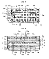
Fig. 1 is a plan view illustrating an example of a holding tray according to the present invention. -
Fig. 2 is a bottom view of the holding tray inFig. 1 . -
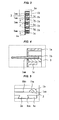
Fig. 3 is a sectional view taken along a Z-Z' line of the holding tray inFig. 1 . -
Fig. 4 is an enlarged view illustrating a state that a guide drill bit is inserted into a portion sectioned with a dotted line of the holding tray inFig. 3 . -
Fig. 5 is an enlarged view of a portion sectioned with a dotted line of the holding tray inFig. 2 . -
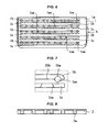
Fig. 6 is a bottom view illustrating an example of a tray main body. -
Fig. 7 is an enlarged view of a portion sectioned with a dotted line of the tray main body inFig. 5 . -
Fig. 8 is a perspective view illustrating an example of a holding member. -
Fig. 9 is a view illustrating a state that the holding tray inFig. 1 is housed in a housing case in a state of a cover being opened. - A holding tray according to the present invention will be described in detail below with reference to the drawings.
- In the drawings, a holding tray X according to the present invention includes a tray
main body 1 and aholding member 2. The holding tray X performs a function for inserting and holding a plurality of drill bits and instruments other than the drill bits which are used for every patient at a time of performing drilling of an embedding hole for a dental implant fixture and following operations after the drilling. As the drill bits inserted into the holding tray X, there are for example, guide drill bits, depth drill bits, pilot drill bits, twist drill bits, counter bore drill bits, and bone taps. Further, as the instruments other than the drill bits, there are for example, direction indicators, fixture drivers, cover screws, fixture drivers, and skill drivers. However, the drill bits and instruments other than the drill bits are not limited to the above if they can be inserted and held in the holding tray X. Furthermore, instruments used in a so-called second stage operation can be also inserted and held in the holding tray X. In addition, for example, as illustrated inFig. 9 , the holding tray X is housed in a housing case Y with a cover Ya made of a hard material capable of autoclave sterilizing, until it is used, is taken out from the housing case Y at a time of use, and is used. - The tray
main body 1 includes a substrate part 1a, aholding plate 1b, and a holdingmember supporting plate 1c. The traymain body 1 is made of a hard member capable of autoclave sterilizing, so that the traymain body 1 can be subjected to the autoclave sterilizing treatment. As the hard member capable of autoclave sterilizing, plastics such as polypropylene, polyether sulfone, polyphenyl sulfone, and the like, or metals such as stainless steel and the like, can be used. - The substrate part 1a is a portion coming to be a base of the tray
main body 1. The substrate part 1a has a plurality of through holes 1aa in which the drill bits and the instruments other than the drill bits are inserted respectively. In addition, inFigs. 1, 2 and6 , the plurality of the through holes 1aa is linearly provided so as to be aligned in a longitudinal direction of the substrate part 1a, and constitutes a hole row. A plurality of the hole rows are arranged in a lateral direction of the substrate part 1a. - If a display part 1ab for displaying an order to use the drill bits is provided on the surface of the substrate 1a, an operator can select a drill bit to be used for every patient according to the order displayed on the display part 1ab, so that it is preferable. More particularly, the display part 1ab displays an order to use a plurality of drill bits in a series for every diameter of a dental implant fixture. The display part 1ab displays the order to use the plurality of drill bits in a series for every diameter of the dental implant fixture, and is provided on the surface of the substrate part 1a by, for example, sticking a seal having a hole on the drill bit displaying portion. Further, if a section display part 1ac for sectioning and displaying locations in which the instruments other than the drill bits are inserted is provided on the surface of the substrate part 1a, the operator can easily select the instruments other than the drill bits at a glance, so that it is preferable. The section display part 1ac sections and displays portions in which the instruments other than the drill bits are inserted, like the display part 1ab, and is provided on the surface of the substrate part 1a by, for example, sticking a seal having a hole on the sectioning and displaying portion. In addition, in the example illustrated in
Fig. 1 , the display part 1ab and the section display part 1ac are provided on the surface of the substrate part 1a by sticking a seal on which the drill bit displaying portion and the sectioning and displaying portion are displayed. - The holding
plates 1b are portions for clamping and holding the drill bits and the instruments other than drill bits, which are inserted into the through holes 1aa respectively, together with the holdingmembers 2 described below, and are erected from a back surface of the substrate part 1a along each of hole rows. The holdingplate 1b basically has a flat plate shape, for example, as illustrated inFigs. 6 and 7 . However, the holdingplate 1b includes half circular cylindrical recessed parts 1ba at portions corresponding to each of through holes 1aa for clamping and holding the drill bits and the instruments other than drill bits, which are inserted into the through holes 1aa respectively, together with the holdingmember 2. - The holding
member supporting plates 1c are portions for detachably clamping and attaching the holdingmember 2 together with the holdingplates 1b, and are erected respectively having a fixed interval with respect to a plane 1bb along the half circular cylindrical recessed part 1ba side of the holdingplate 1b. In addition, if the holdingmember supporting part 1c includes a plurality of fitting cutout parts 1ca, for example, as illustrated inFigs. 6 and 7 , the holdingmember 2 can be held without causing a positional shift. - The holding
members 2 are members for clamping and holding the drill bits and the instruments other than the drill bits, which are inserted into through hole 1aa respectively, together with the half circular cylindrical recessed parts 1ba of the holdingplates 1b. The holdingmembers 2 are detachably clamped and attached between the holdingplates 1b and the holdingmember supporting plates 1c, which are erected along the hole rows of the substrate part 1a. Further, the holdingmember 2 is made of an elastic member capable of autoclave sterilizing, such as a rubber or the like, so that the holdingmember 2 can be subjected to the autoclave sterilizing treatment. In addition, for example, as illustrated inFig. 8 , if a projection part for fitting 2a is provided for fitting to each fitting cutout part 1ca of the holdingmember supporting plate 1c, the holdingmember 2 can be held without causing a positional shift. - In the holding tray X having the aforementioned configuration, when each of the drill bits and the instruments other than the drill bits are respectively inserted into the through holes 1aa, each of the drill bits and the instruments other than the drill bits are clamped and held between the half circular cylindrical recessed parts 1ba of the holding
plate 1b and the holdingmember 2, for example, as illustrated inFig. 4 . Thus, each of the drill bits and the instruments other than the drill bits can be inserted and held in the through holes 1aa respectively so as to have a state of being easily taken out at a time of use. Further, a rubber grommet is not fitted to each through hole 1aa, but the holdingmembers 2 are detachably clamped and attached between the holdingplates 1b and the holdingmember supporting plates 1c, which are erected along the hole rows of the substrate part 1a, as illustrated inFig. 2 . Furthermore, the traymain body 1 and the holdingmember 2 are made of materials capable of autoclave sterilizing. Thus, after using the holding tray X, the holdingmembers 2 and the traymain body 1 can be easily washed by only taking out the holdingmembers 2 from places between the holdingplates 1b of the traymain body 1 and the holdingmember supporting plates 1c. Furthermore, the autoclave sterilizing treatment can be performed by only attaching the holdingmembers 2 between the holdingplates 1b of the traymain body 1 and the holdingmember supporting plates 1c after the washing operation. Therefore, the washing and sterilizing treatment operations can be performed easily. - Further, if the display part 1ab for displaying an order to use the drill bits is provided on the surface of the substrate part 1a of the tray
main body 1, an operator can select a drill bit to be used according to the order displayed on the display part 1ab, so that it is preferable. - Furthermore, if the section display part 1ac for sectioning and displaying locations in which the instruments other than the drill bits are inserted is provided on the surface of the substrate part 1a of the tray
main body 1, the operator can easily select the instruments other than the drill bits at a glance, so that it is preferable.
Claims (3)
- A holding tray (X) for inserting and holding a plurality of drill bits and instruments other than the drill bits used for every patient at a time of drilling of an embedding hole for a dental implant fixture and following operations after the drilling, the holding tray (X) comprising:a tray main body (1) made of a hard material capable of autoclave sterilizing, wherein the tray main body (1) comprises holding plates (1b) and holding member supporting plates (1c) on a back surface of a substrate part (1a) having a plurality of hole rows consisting of a plurality of linearly aligned through holes (1aa) in which each of the drill bits and instruments other than the drill bits are inserted, wherein the holding plates (1b) are erected along the hole rows, have a flat plate shape, and include half circular cylindrical recessed parts (1ba) at portions corresponding to each of the through holes (1aa), andwherein the holding member supporting plates (1c) are erected respectively having a fixed interval with respect to a plane (1bb) along the half circular cylindrical recessed part (1ba)side of the holding plate (1b); and holding members (2) made of an elastic material capable of autoclave sterilizing, wherein the holding members (2) are detachably clamped and attached between the holding plates (1b) and the holding member supporting plates (1c), and clamp and hold the drill bits and the instruments other than the drill bits inserted into the through holes (1aa) in the hole rows, together with the half circular cylindrical recessed parts (1ba) of the holding plates (1b).
- The holding tray as claimed in claim 1,
wherein a display part (1ab) for displaying an order to use drill bits is provided on a surface of the substrate part (1a) of the tray main body (1). - The holding tray as claimed in claim 1 or 2, wherein a section display part (1ac) for sectioning and displaying locations in which the instruments other than the drill bits are inserted provided on the surface of the substrate part (1a) of the tray main body (1).
Applications Claiming Priority (1)
| Application Number | Priority Date | Filing Date | Title |
|---|---|---|---|
| JP2009282803A JP2011120816A (en) | 2009-12-14 | 2009-12-14 | Holding tray |
Publications (2)
| Publication Number | Publication Date |
|---|---|
| EP2332487A1 true EP2332487A1 (en) | 2011-06-15 |
| EP2332487B1 EP2332487B1 (en) | 2013-11-06 |
Family
ID=43598047
Family Applications (1)
| Application Number | Title | Priority Date | Filing Date |
|---|---|---|---|
| EP10015483.0A Not-in-force EP2332487B1 (en) | 2009-12-14 | 2010-12-09 | Holding tray |
Country Status (3)
| Country | Link |
|---|---|
| US (1) | US8074799B2 (en) |
| EP (1) | EP2332487B1 (en) |
| JP (1) | JP2011120816A (en) |
Cited By (2)
| Publication number | Priority date | Publication date | Assignee | Title |
|---|---|---|---|---|
| US9072560B2 (en) | 2011-10-12 | 2015-07-07 | Warsaw Orthopedic, Inc. | Implant removal aid for use with implants utilizing a data carrier |
| EP3636216A2 (en) * | 2018-10-08 | 2020-04-15 | Biomet 3I, LLC | Dental surgical trays |
Families Citing this family (6)
| Publication number | Priority date | Publication date | Assignee | Title |
|---|---|---|---|---|
| DE202012103066U1 (en) | 2012-08-14 | 2012-09-05 | Heliocos Gmbh | Holding device for holding medical micro tools |
| ES2875598T3 (en) * | 2015-03-09 | 2021-11-10 | Straumann Holding Ag | Medical instrument storage case |
| CN109316262B (en) * | 2018-11-15 | 2025-03-14 | 徐海 | Medical positioning device for gutta-percha tips |
| DE102021106111A1 (en) * | 2021-03-12 | 2022-09-15 | Aesculap Ag | Recording expander sleeve and tool set |
| DE102021106110A1 (en) * | 2021-03-12 | 2022-09-15 | Aesculap Ag | Recording expander sleeve and tool set |
| US11819399B2 (en) * | 2021-07-06 | 2023-11-21 | Wright Medical Technology, Inc. | Systems and methods of plate trial packaging |
Citations (6)
| Publication number | Priority date | Publication date | Assignee | Title |
|---|---|---|---|---|
| FR1024588A (en) * | 1950-09-14 | 1953-04-02 | Fraises Dentaires Fab De | Packaging device for elongated parts, such as dental burs or the like |
| GB2329337A (en) * | 1997-09-18 | 1999-03-24 | Powell Cullingford Andrew Will | Dental root canal instrument |
| US6328565B1 (en) * | 1999-09-29 | 2001-12-11 | Brasseler Usa 1 Lp | Training method and apparatus for dental bur identification |
| WO2006071180A1 (en) * | 2004-12-30 | 2006-07-06 | Nobel Biocare Services Ag | Unit for holding instruments and components for dental treatment |
| DE202007004638U1 (en) * | 2007-03-22 | 2007-06-14 | Aesculap Ag & Co. Kg | Holding device for an implant |
| US20090266728A1 (en) * | 2008-04-25 | 2009-10-29 | Warsaw Orthopedic, Inc. | Medical device tracking system with tray and method |
Family Cites Families (9)
| Publication number | Priority date | Publication date | Assignee | Title |
|---|---|---|---|---|
| US1451806A (en) * | 1922-05-26 | 1923-04-17 | Joseph E Baldridge | Dental tool holder |
| US3270416A (en) * | 1963-07-02 | 1966-09-06 | Leo A Feula | Burr dispenser |
| US5525314A (en) * | 1994-09-26 | 1996-06-11 | Bausch & Lomb Incorporated | Surgical tool container system |
| US6474481B1 (en) * | 2001-06-08 | 2002-11-05 | Yung-Yuan Liu | Flexible tool storage device |
| US20040069668A1 (en) * | 2002-10-09 | 2004-04-15 | Robert Finnigan | Tool-element holding case |
| US7401700B2 (en) * | 2005-02-22 | 2008-07-22 | Robert Bosch Gmbh | Tool accessory case index |
| US7544336B2 (en) * | 2005-11-07 | 2009-06-09 | Andrew Powell | Sterilization tray with base and elastomeric lid |
| US8342841B2 (en) * | 2008-07-30 | 2013-01-01 | Zimmer Dental, Inc. | Procedure specific storage block for holding implant containers and surgical tools |
| US7896158B2 (en) * | 2008-09-23 | 2011-03-01 | Curtis Taylor | Tool bit holder |
-
2009
- 2009-12-14 JP JP2009282803A patent/JP2011120816A/en active Pending
-
2010
- 2010-12-07 US US12/961,915 patent/US8074799B2/en not_active Expired - Fee Related
- 2010-12-09 EP EP10015483.0A patent/EP2332487B1/en not_active Not-in-force
Patent Citations (7)
| Publication number | Priority date | Publication date | Assignee | Title |
|---|---|---|---|---|
| FR1024588A (en) * | 1950-09-14 | 1953-04-02 | Fraises Dentaires Fab De | Packaging device for elongated parts, such as dental burs or the like |
| GB2329337A (en) * | 1997-09-18 | 1999-03-24 | Powell Cullingford Andrew Will | Dental root canal instrument |
| US6328565B1 (en) * | 1999-09-29 | 2001-12-11 | Brasseler Usa 1 Lp | Training method and apparatus for dental bur identification |
| WO2006071180A1 (en) * | 2004-12-30 | 2006-07-06 | Nobel Biocare Services Ag | Unit for holding instruments and components for dental treatment |
| JP2008526298A (en) | 2004-12-30 | 2008-07-24 | ノベル バイオケア サーヴィシィズ アーゲー | Device for holding instruments and elements for dental treatment |
| DE202007004638U1 (en) * | 2007-03-22 | 2007-06-14 | Aesculap Ag & Co. Kg | Holding device for an implant |
| US20090266728A1 (en) * | 2008-04-25 | 2009-10-29 | Warsaw Orthopedic, Inc. | Medical device tracking system with tray and method |
Cited By (2)
| Publication number | Priority date | Publication date | Assignee | Title |
|---|---|---|---|---|
| US9072560B2 (en) | 2011-10-12 | 2015-07-07 | Warsaw Orthopedic, Inc. | Implant removal aid for use with implants utilizing a data carrier |
| EP3636216A2 (en) * | 2018-10-08 | 2020-04-15 | Biomet 3I, LLC | Dental surgical trays |
Also Published As
| Publication number | Publication date |
|---|---|
| EP2332487B1 (en) | 2013-11-06 |
| US8074799B2 (en) | 2011-12-13 |
| US20110139651A1 (en) | 2011-06-16 |
| JP2011120816A (en) | 2011-06-23 |
Similar Documents
| Publication | Publication Date | Title |
|---|---|---|
| EP2332487B1 (en) | Holding tray | |
| EP2276416B1 (en) | Method for pre-operative visualization of instrumentation used with a surgical guide for dental implant placement | |
| EP3075344B1 (en) | Method for providing guide information of operation using a surgical guide for a dental implant | |
| EP2060240A2 (en) | Components for use with a surgical guide for dental implant placement | |
| JP4942120B2 (en) | Medical cutting tool guide | |
| EP2572671A1 (en) | Stopper ring for a bone drill | |
| US8535055B2 (en) | Method and kit for producing dental implant drilling guides | |
| US8858228B2 (en) | Method and kit for dental implant drilling guides | |
| US9782235B2 (en) | Implant surgical guide apparatus | |
| US8911233B2 (en) | Dental bur storage device | |
| EP1212004A1 (en) | Kit for immediate post-extraction implantation | |
| KR101566456B1 (en) | Drill for implant and apparatus having the same | |
| US20100028828A1 (en) | Procedure specific storage block for holding implant containers and surgical tools | |
| EP2123236A1 (en) | Detachable stopper for dental drill | |
| KR20140056816A (en) | Abutment holder for implanting | |
| WO2007067105A1 (en) | A surgical tool for a dental implant procedure, a tool kit for a dental implant procedure and a method for making a dental implant | |
| KR100995836B1 (en) | Implant device | |
| KR20240165139A (en) | Kit for storing implant surgical equipment and method for using the same | |
| KR102190282B1 (en) | Tool kit tray for preparing dental implant surgery | |
| AU2021103111A4 (en) | An apparatus to hold crown during crown manipulations | |
| CN223095640U (en) | Improved digital positioning depth fixing guide plate | |
| KR20200046971A (en) | Tray set for preparing dental implant surgery | |
| KR20200078964A (en) | Group designation type kit for customized dental implant surgery | |
| US9763755B2 (en) | Surgical kit for precise vertical positioning of dental implants | |
| WO2013138308A1 (en) | Method and kit for dental implant drilling guides |
Legal Events
| Date | Code | Title | Description |
|---|---|---|---|
| PUAI | Public reference made under article 153(3) epc to a published international application that has entered the european phase |
Free format text: ORIGINAL CODE: 0009012 |
|
| AK | Designated contracting states |
Kind code of ref document: A1 Designated state(s): AL AT BE BG CH CY CZ DE DK EE ES FI FR GB GR HR HU IE IS IT LI LT LU LV MC MK MT NL NO PL PT RO RS SE SI SK SM TR |
|
| AX | Request for extension of the european patent |
Extension state: BA ME |
|
| 17P | Request for examination filed |
Effective date: 20110728 |
|
| GRAP | Despatch of communication of intention to grant a patent |
Free format text: ORIGINAL CODE: EPIDOSNIGR1 |
|
| INTG | Intention to grant announced |
Effective date: 20130521 |
|
| RIN1 | Information on inventor provided before grant (corrected) |
Inventor name: FUJII, NAOTO Inventor name: ISHIKAWA, YUSUKE |
|
| GRAS | Grant fee paid |
Free format text: ORIGINAL CODE: EPIDOSNIGR3 |
|
| GRAA | (expected) grant |
Free format text: ORIGINAL CODE: 0009210 |
|
| AK | Designated contracting states |
Kind code of ref document: B1 Designated state(s): AL AT BE BG CH CY CZ DE DK EE ES FI FR GB GR HR HU IE IS IT LI LT LU LV MC MK MT NL NO PL PT RO RS SE SI SK SM TR |
|
| REG | Reference to a national code |
Ref country code: GB Ref legal event code: FG4D |
|
| REG | Reference to a national code |
Ref country code: CH Ref legal event code: EP |
|
| REG | Reference to a national code |
Ref country code: AT Ref legal event code: REF Ref document number: 638882 Country of ref document: AT Kind code of ref document: T Effective date: 20131215 |
|
| REG | Reference to a national code |
Ref country code: IE Ref legal event code: FG4D |
|
| REG | Reference to a national code |
Ref country code: DE Ref legal event code: R096 Ref document number: 602010011394 Country of ref document: DE Effective date: 20140102 |
|
| REG | Reference to a national code |
Ref country code: NL Ref legal event code: VDEP Effective date: 20131106 |
|
| REG | Reference to a national code |
Ref country code: AT Ref legal event code: MK05 Ref document number: 638882 Country of ref document: AT Kind code of ref document: T Effective date: 20131106 |
|
| REG | Reference to a national code |
Ref country code: LT Ref legal event code: MG4D |
|
| PG25 | Lapsed in a contracting state [announced via postgrant information from national office to epo] |
Ref country code: NL Free format text: LAPSE BECAUSE OF FAILURE TO SUBMIT A TRANSLATION OF THE DESCRIPTION OR TO PAY THE FEE WITHIN THE PRESCRIBED TIME-LIMIT Effective date: 20131106 Ref country code: IS Free format text: LAPSE BECAUSE OF FAILURE TO SUBMIT A TRANSLATION OF THE DESCRIPTION OR TO PAY THE FEE WITHIN THE PRESCRIBED TIME-LIMIT Effective date: 20140306 Ref country code: HR Free format text: LAPSE BECAUSE OF FAILURE TO SUBMIT A TRANSLATION OF THE DESCRIPTION OR TO PAY THE FEE WITHIN THE PRESCRIBED TIME-LIMIT Effective date: 20131106 Ref country code: NO Free format text: LAPSE BECAUSE OF FAILURE TO SUBMIT A TRANSLATION OF THE DESCRIPTION OR TO PAY THE FEE WITHIN THE PRESCRIBED TIME-LIMIT Effective date: 20140206 Ref country code: SE Free format text: LAPSE BECAUSE OF FAILURE TO SUBMIT A TRANSLATION OF THE DESCRIPTION OR TO PAY THE FEE WITHIN THE PRESCRIBED TIME-LIMIT Effective date: 20131106 Ref country code: FI Free format text: LAPSE BECAUSE OF FAILURE TO SUBMIT A TRANSLATION OF THE DESCRIPTION OR TO PAY THE FEE WITHIN THE PRESCRIBED TIME-LIMIT Effective date: 20131106 Ref country code: LT Free format text: LAPSE BECAUSE OF FAILURE TO SUBMIT A TRANSLATION OF THE DESCRIPTION OR TO PAY THE FEE WITHIN THE PRESCRIBED TIME-LIMIT Effective date: 20131106 |
|
| PG25 | Lapsed in a contracting state [announced via postgrant information from national office to epo] |
Ref country code: RS Free format text: LAPSE BECAUSE OF FAILURE TO SUBMIT A TRANSLATION OF THE DESCRIPTION OR TO PAY THE FEE WITHIN THE PRESCRIBED TIME-LIMIT Effective date: 20131106 Ref country code: LV Free format text: LAPSE BECAUSE OF FAILURE TO SUBMIT A TRANSLATION OF THE DESCRIPTION OR TO PAY THE FEE WITHIN THE PRESCRIBED TIME-LIMIT Effective date: 20131106 Ref country code: AT Free format text: LAPSE BECAUSE OF FAILURE TO SUBMIT A TRANSLATION OF THE DESCRIPTION OR TO PAY THE FEE WITHIN THE PRESCRIBED TIME-LIMIT Effective date: 20131106 Ref country code: ES Free format text: LAPSE BECAUSE OF FAILURE TO SUBMIT A TRANSLATION OF THE DESCRIPTION OR TO PAY THE FEE WITHIN THE PRESCRIBED TIME-LIMIT Effective date: 20131106 Ref country code: BE Free format text: LAPSE BECAUSE OF FAILURE TO SUBMIT A TRANSLATION OF THE DESCRIPTION OR TO PAY THE FEE WITHIN THE PRESCRIBED TIME-LIMIT Effective date: 20131106 |
|
| PG25 | Lapsed in a contracting state [announced via postgrant information from national office to epo] |
Ref country code: PT Free format text: LAPSE BECAUSE OF FAILURE TO SUBMIT A TRANSLATION OF THE DESCRIPTION OR TO PAY THE FEE WITHIN THE PRESCRIBED TIME-LIMIT Effective date: 20140306 |
|
| PG25 | Lapsed in a contracting state [announced via postgrant information from national office to epo] |
Ref country code: EE Free format text: LAPSE BECAUSE OF FAILURE TO SUBMIT A TRANSLATION OF THE DESCRIPTION OR TO PAY THE FEE WITHIN THE PRESCRIBED TIME-LIMIT Effective date: 20131106 |
|
| REG | Reference to a national code |
Ref country code: DE Ref legal event code: R097 Ref document number: 602010011394 Country of ref document: DE |
|
| PG25 | Lapsed in a contracting state [announced via postgrant information from national office to epo] |
Ref country code: CZ Free format text: LAPSE BECAUSE OF FAILURE TO SUBMIT A TRANSLATION OF THE DESCRIPTION OR TO PAY THE FEE WITHIN THE PRESCRIBED TIME-LIMIT Effective date: 20131106 Ref country code: SK Free format text: LAPSE BECAUSE OF FAILURE TO SUBMIT A TRANSLATION OF THE DESCRIPTION OR TO PAY THE FEE WITHIN THE PRESCRIBED TIME-LIMIT Effective date: 20131106 Ref country code: IT Free format text: LAPSE BECAUSE OF FAILURE TO SUBMIT A TRANSLATION OF THE DESCRIPTION OR TO PAY THE FEE WITHIN THE PRESCRIBED TIME-LIMIT Effective date: 20131106 Ref country code: PL Free format text: LAPSE BECAUSE OF FAILURE TO SUBMIT A TRANSLATION OF THE DESCRIPTION OR TO PAY THE FEE WITHIN THE PRESCRIBED TIME-LIMIT Effective date: 20131106 Ref country code: RO Free format text: LAPSE BECAUSE OF FAILURE TO SUBMIT A TRANSLATION OF THE DESCRIPTION OR TO PAY THE FEE WITHIN THE PRESCRIBED TIME-LIMIT Effective date: 20131106 Ref country code: MC Free format text: LAPSE BECAUSE OF FAILURE TO SUBMIT A TRANSLATION OF THE DESCRIPTION OR TO PAY THE FEE WITHIN THE PRESCRIBED TIME-LIMIT Effective date: 20131106 |
|
| PLBE | No opposition filed within time limit |
Free format text: ORIGINAL CODE: 0009261 |
|
| STAA | Information on the status of an ep patent application or granted ep patent |
Free format text: STATUS: NO OPPOSITION FILED WITHIN TIME LIMIT |
|
| REG | Reference to a national code |
Ref country code: IE Ref legal event code: MM4A |
|
| PG25 | Lapsed in a contracting state [announced via postgrant information from national office to epo] |
Ref country code: DK Free format text: LAPSE BECAUSE OF FAILURE TO SUBMIT A TRANSLATION OF THE DESCRIPTION OR TO PAY THE FEE WITHIN THE PRESCRIBED TIME-LIMIT Effective date: 20131106 |
|
| 26N | No opposition filed |
Effective date: 20140807 |
|
| PG25 | Lapsed in a contracting state [announced via postgrant information from national office to epo] |
Ref country code: IE Free format text: LAPSE BECAUSE OF NON-PAYMENT OF DUE FEES Effective date: 20131209 |
|
| REG | Reference to a national code |
Ref country code: DE Ref legal event code: R097 Ref document number: 602010011394 Country of ref document: DE Effective date: 20140807 |
|
| PG25 | Lapsed in a contracting state [announced via postgrant information from national office to epo] |
Ref country code: SI Free format text: LAPSE BECAUSE OF FAILURE TO SUBMIT A TRANSLATION OF THE DESCRIPTION OR TO PAY THE FEE WITHIN THE PRESCRIBED TIME-LIMIT Effective date: 20131106 |
|
| PG25 | Lapsed in a contracting state [announced via postgrant information from national office to epo] |
Ref country code: SM Free format text: LAPSE BECAUSE OF FAILURE TO SUBMIT A TRANSLATION OF THE DESCRIPTION OR TO PAY THE FEE WITHIN THE PRESCRIBED TIME-LIMIT Effective date: 20131106 |
|
| PG25 | Lapsed in a contracting state [announced via postgrant information from national office to epo] |
Ref country code: CY Free format text: LAPSE BECAUSE OF FAILURE TO SUBMIT A TRANSLATION OF THE DESCRIPTION OR TO PAY THE FEE WITHIN THE PRESCRIBED TIME-LIMIT Effective date: 20131106 Ref country code: TR Free format text: LAPSE BECAUSE OF FAILURE TO SUBMIT A TRANSLATION OF THE DESCRIPTION OR TO PAY THE FEE WITHIN THE PRESCRIBED TIME-LIMIT Effective date: 20131106 |
|
| PG25 | Lapsed in a contracting state [announced via postgrant information from national office to epo] |
Ref country code: LU Free format text: LAPSE BECAUSE OF NON-PAYMENT OF DUE FEES Effective date: 20131209 Ref country code: MK Free format text: LAPSE BECAUSE OF FAILURE TO SUBMIT A TRANSLATION OF THE DESCRIPTION OR TO PAY THE FEE WITHIN THE PRESCRIBED TIME-LIMIT Effective date: 20131106 Ref country code: HU Free format text: LAPSE BECAUSE OF FAILURE TO SUBMIT A TRANSLATION OF THE DESCRIPTION OR TO PAY THE FEE WITHIN THE PRESCRIBED TIME-LIMIT; INVALID AB INITIO Effective date: 20101209 Ref country code: BG Free format text: LAPSE BECAUSE OF FAILURE TO SUBMIT A TRANSLATION OF THE DESCRIPTION OR TO PAY THE FEE WITHIN THE PRESCRIBED TIME-LIMIT Effective date: 20131106 |
|
| REG | Reference to a national code |
Ref country code: CH Ref legal event code: PL |
|
| PG25 | Lapsed in a contracting state [announced via postgrant information from national office to epo] |
Ref country code: MT Free format text: LAPSE BECAUSE OF FAILURE TO SUBMIT A TRANSLATION OF THE DESCRIPTION OR TO PAY THE FEE WITHIN THE PRESCRIBED TIME-LIMIT Effective date: 20131106 Ref country code: GR Free format text: LAPSE BECAUSE OF NON-PAYMENT OF DUE FEES Effective date: 20131106 |
|
| PG25 | Lapsed in a contracting state [announced via postgrant information from national office to epo] |
Ref country code: LI Free format text: LAPSE BECAUSE OF NON-PAYMENT OF DUE FEES Effective date: 20141231 Ref country code: CH Free format text: LAPSE BECAUSE OF NON-PAYMENT OF DUE FEES Effective date: 20141231 |
|
| REG | Reference to a national code |
Ref country code: FR Ref legal event code: PLFP Year of fee payment: 6 |
|
| PG25 | Lapsed in a contracting state [announced via postgrant information from national office to epo] |
Ref country code: GR Free format text: LAPSE BECAUSE OF FAILURE TO SUBMIT A TRANSLATION OF THE DESCRIPTION OR TO PAY THE FEE WITHIN THE PRESCRIBED TIME-LIMIT Effective date: 20140207 |
|
| REG | Reference to a national code |
Ref country code: FR Ref legal event code: PLFP Year of fee payment: 7 |
|
| REG | Reference to a national code |
Ref country code: FR Ref legal event code: PLFP Year of fee payment: 8 |
|
| PG25 | Lapsed in a contracting state [announced via postgrant information from national office to epo] |
Ref country code: AL Free format text: LAPSE BECAUSE OF FAILURE TO SUBMIT A TRANSLATION OF THE DESCRIPTION OR TO PAY THE FEE WITHIN THE PRESCRIBED TIME-LIMIT Effective date: 20131106 |
|
| PGFP | Annual fee paid to national office [announced via postgrant information from national office to epo] |
Ref country code: GB Payment date: 20221215 Year of fee payment: 13 Ref country code: FR Payment date: 20221215 Year of fee payment: 13 Ref country code: DE Payment date: 20221213 Year of fee payment: 13 |
|
| P01 | Opt-out of the competence of the unified patent court (upc) registered |
Effective date: 20230502 |
|
| REG | Reference to a national code |
Ref country code: DE Ref legal event code: R119 Ref document number: 602010011394 Country of ref document: DE |
|
| GBPC | Gb: european patent ceased through non-payment of renewal fee |
Effective date: 20231209 |
|
| PG25 | Lapsed in a contracting state [announced via postgrant information from national office to epo] |
Ref country code: DE Free format text: LAPSE BECAUSE OF NON-PAYMENT OF DUE FEES Effective date: 20240702 |
|
| PG25 | Lapsed in a contracting state [announced via postgrant information from national office to epo] |
Ref country code: GB Free format text: LAPSE BECAUSE OF NON-PAYMENT OF DUE FEES Effective date: 20231209 |
|
| PG25 | Lapsed in a contracting state [announced via postgrant information from national office to epo] |
Ref country code: FR Free format text: LAPSE BECAUSE OF NON-PAYMENT OF DUE FEES Effective date: 20231231 |
|
| PG25 | Lapsed in a contracting state [announced via postgrant information from national office to epo] |
Ref country code: GB Free format text: LAPSE BECAUSE OF NON-PAYMENT OF DUE FEES Effective date: 20231209 Ref country code: FR Free format text: LAPSE BECAUSE OF NON-PAYMENT OF DUE FEES Effective date: 20231231 Ref country code: DE Free format text: LAPSE BECAUSE OF NON-PAYMENT OF DUE FEES Effective date: 20240702 |