EP2332469A1 - Endoscope excluder - Google Patents
Endoscope excluder Download PDFInfo
- Publication number
- EP2332469A1 EP2332469A1 EP09809895A EP09809895A EP2332469A1 EP 2332469 A1 EP2332469 A1 EP 2332469A1 EP 09809895 A EP09809895 A EP 09809895A EP 09809895 A EP09809895 A EP 09809895A EP 2332469 A1 EP2332469 A1 EP 2332469A1
- Authority
- EP
- European Patent Office
- Prior art keywords
- excluder
- axis
- endoscope
- along
- frame
- Prior art date
- Legal status (The legal status is an assumption and is not a legal conclusion. Google has not performed a legal analysis and makes no representation as to the accuracy of the status listed.)
- Granted
Links
Images





Classifications
-
- A—HUMAN NECESSITIES
- A61—MEDICAL OR VETERINARY SCIENCE; HYGIENE
- A61B—DIAGNOSIS; SURGERY; IDENTIFICATION
- A61B17/00—Surgical instruments, devices or methods
- A61B17/02—Surgical instruments, devices or methods for holding wounds open, e.g. retractors; Tractors
-
- A—HUMAN NECESSITIES
- A61—MEDICAL OR VETERINARY SCIENCE; HYGIENE
- A61B—DIAGNOSIS; SURGERY; IDENTIFICATION
- A61B17/00—Surgical instruments, devices or methods
- A61B17/02—Surgical instruments, devices or methods for holding wounds open, e.g. retractors; Tractors
- A61B17/0218—Surgical instruments, devices or methods for holding wounds open, e.g. retractors; Tractors for minimally invasive surgery
-
- A—HUMAN NECESSITIES
- A61—MEDICAL OR VETERINARY SCIENCE; HYGIENE
- A61B—DIAGNOSIS; SURGERY; IDENTIFICATION
- A61B17/00—Surgical instruments, devices or methods
-
- A—HUMAN NECESSITIES
- A61—MEDICAL OR VETERINARY SCIENCE; HYGIENE
- A61L—METHODS OR APPARATUS FOR STERILISING MATERIALS OR OBJECTS IN GENERAL; DISINFECTION, STERILISATION OR DEODORISATION OF AIR; CHEMICAL ASPECTS OF BANDAGES, DRESSINGS, ABSORBENT PADS OR SURGICAL ARTICLES; MATERIALS FOR BANDAGES, DRESSINGS, ABSORBENT PADS OR SURGICAL ARTICLES
- A61L31/00—Materials for other surgical articles, e.g. stents, stent-grafts, shunts, surgical drapes, guide wires, materials for adhesion prevention, occluding devices, surgical gloves, tissue fixation devices
-
- A—HUMAN NECESSITIES
- A61—MEDICAL OR VETERINARY SCIENCE; HYGIENE
- A61B—DIAGNOSIS; SURGERY; IDENTIFICATION
- A61B17/00—Surgical instruments, devices or methods
- A61B17/00234—Surgical instruments, devices or methods for minimally invasive surgery
- A61B2017/00292—Surgical instruments, devices or methods for minimally invasive surgery mounted on or guided by flexible, e.g. catheter-like, means
- A61B2017/0034—Surgical instruments, devices or methods for minimally invasive surgery mounted on or guided by flexible, e.g. catheter-like, means adapted to be inserted through a working channel of an endoscope
-
- A—HUMAN NECESSITIES
- A61—MEDICAL OR VETERINARY SCIENCE; HYGIENE
- A61B—DIAGNOSIS; SURGERY; IDENTIFICATION
- A61B17/00—Surgical instruments, devices or methods
- A61B17/0057—Implements for plugging an opening in the wall of a hollow or tubular organ, e.g. for sealing a vessel puncture or closing a cardiac septal defect
- A61B2017/00637—Implements for plugging an opening in the wall of a hollow or tubular organ, e.g. for sealing a vessel puncture or closing a cardiac septal defect for sealing trocar wounds through abdominal wall
-
- A—HUMAN NECESSITIES
- A61—MEDICAL OR VETERINARY SCIENCE; HYGIENE
- A61B—DIAGNOSIS; SURGERY; IDENTIFICATION
- A61B17/00—Surgical instruments, devices or methods
- A61B2017/00831—Material properties
- A61B2017/00898—Material properties expandable upon contact with fluid
-
- A—HUMAN NECESSITIES
- A61—MEDICAL OR VETERINARY SCIENCE; HYGIENE
- A61B—DIAGNOSIS; SURGERY; IDENTIFICATION
- A61B17/00—Surgical instruments, devices or methods
- A61B2017/00831—Material properties
- A61B2017/00942—Material properties hydrophilic
-
- A—HUMAN NECESSITIES
- A61—MEDICAL OR VETERINARY SCIENCE; HYGIENE
- A61B—DIAGNOSIS; SURGERY; IDENTIFICATION
- A61B17/00—Surgical instruments, devices or methods
- A61B17/32—Surgical cutting instruments
- A61B2017/320044—Blunt dissectors
-
- A—HUMAN NECESSITIES
- A61—MEDICAL OR VETERINARY SCIENCE; HYGIENE
- A61B—DIAGNOSIS; SURGERY; IDENTIFICATION
- A61B17/00—Surgical instruments, devices or methods
- A61B17/32—Surgical cutting instruments
- A61B2017/320044—Blunt dissectors
- A61B2017/320048—Balloon dissectors
Definitions
- an abdominal region or a chest region has been widely incised in a conventional surgical operation.
- endoscopic surgeries are often executed in recent years.
- trocars also called as trockars
- a camera or a surgical instrument in an elongate shape such as an endoscopic forceps or an endoscopic knife
- the endoscopic surgeries are less invasive and apply low impact to patients.
- Patent Document 2 describes an excluder (a support forceps) provided with a balloon at a tip end thereof.
- This excluder is inserted into a body cavity through a trocar with the balloon being folded and accommodated in a cylindrical haft. The haft is then slid to expose the balloon, into which gas is injected, so that the expanded balloon excludes or supports an organ. After the use thereof, the balloon is degassed and folded to be accommodated in the cylindrical haft, and the excluder is removed from the trocar.
- an endoscope excluder used in an endoscopic surgery comprises an excluder body made of a hygroscopically expanding material that is obtained by drying and compression molding, wherein the excluder body has a bar shape and a transverse section smaller than a section of a cylindrical inner cavity of a trocar.
- the above expression "obtained by drying and compression molding” refers to a case of compressing and drying at one time by performing compression molding while drying, as well as a case of initially compressing and then drying in such a compressed state.
- drying and performing compression molding may be occasionally referred to as “drying and compression molding”.
- the "hygroscopically expanding material” has a property of expanding by absorption of moisture.
- the excluder body has the transverse section smaller than the section of the cylindrical inner cavity of the trocar. Accordingly, the excluder can be inserted into a body cavity through the cylindrical portion of the trocar. Further, the excluder body is made of the hygroscopically expanding material obtained by drying and compression molding. Therefore, the excluder body is swollen to be increased in size when moisture is applied thereto.
- the excluder body smaller than the section of the cylindrical inner cavity of the trocar is not large enough to exclude an organ.
- physiological saline or the like is poured on the excluder body after the endoscope excluder is inserted into a body cavity, the excluder body is swollen and increased in size so as to exclude an organ.
- the hygroscopically expanding material having been swollen has an appropriate repulsive force, an untargeted organ can be excluded by the excluder body that is made of the hygroscopically expanding material having been swollen.
- the excluder body which is made of the hygroscopically expanding material having been swollen, is freely bendable and easily handled, and is capable of gently excluding an untargeted organ.
- the above endoscope excluder of the present invention does not need manpower for supporting the excluder to keep the excluding state, or there is no need to provide an additional hole for the excluder in the body of a patient, unlike the endoscope excluders described in Patent Documents 1 and 2. Further, the endoscope excluder of the present invention does not have a hard frame portion, so that the swollen excluder body in the present invention is capable of gently excluding an untargeted organ.
- the excluder body having been dried and compressed is sized to be smaller than the section of the cylindrical inner cavity of the trocar, the excluder body may possibly absorb moisture in the air to be slightly expanded, which will result in a state where the diagonal lines of the transverse section of the excluder body are each as long as the diameter of the section of the cylindrical inner cavity of the trocar.
- the excluder body is made of a slightly flexible material in a dried and compressed state, the excluder body can be inserted through the trocar while the surfaces of the excluder body are in contact with the inner wall surface of the trocar. Accordingly, such an excluder body can be still expressed as "shorter". Therefore, the present invention also includes a case where the excluder body slightly expanded is as large as the section of the cylindrical inner cavity of the trocar.
- this sponge excluder for laparotomy is large (260 mm x 90 mm x 35 mm or 120 mm x 90 mm x 35 mm, for example). Accordingly, this sponge excluder cannot be inserted through the cylindrical portion of a thin trocar. However, the excluder is required to have a certain size for exclusion. No organ can be excluded by a sponge excluder that is thin enough to pass through the cylindrical portion of the trocar.
- the endoscope excluder of the present invention which is thin as described above, can be inserted through the cylindrical portion of the trocar. Moreover, because the excluder is sufficiently dried and compressed, the excluder can be swollen and increased in size. Therefore, an organ can be excluded by the excluder that is swollen and increased in size.
- the excluder body in the bar shape according to the present invention is obtained by drying and compression molding.
- the excluder body is preferably compressed at least from sides of the bar (from opposing sides intersecting with the longitudinal direction).
- the excluder body in the bar shape has a long axis that is defined to be aligned with a Z axis, and the hygroscopically expanding material is preferably compressed in directions perpendicular to the Z axis(see an arrow A in Figs.1(a) described below, for example).
- the excluder body when moisture is applied, the excluder body is swollen and expanded in the directions of the sides of the bar (in the directions of increasing the width of the bar).
- the excluder body in the dried and compressed state is smaller than the cylindrical inner cavity of the trocar, the excluder body is changed into a plate shape and is capable of easily excluding an organ when being swollen after having been inserted into a body cavity.
- the endoscope excluder further comprises a long frame that accommodates the excluder body so as to be taken out thereof, wherein sides perpendicular to the compression directions of the excluder body are preferably provided with paired support walls facing each other along the Z axis. More specifically, the endoscope excluder is provided with the frame, which preferably has the support walls on the compressed surfaces of the excluder body.
- a frame excluder such an endoscope excluder provided with a frame is referred to as a "framed excluder”
- an excluder provided with no frame is simply referred to as an "endoscope excluder" or an “excluder”, for the purpose of distinction therebetween.
- the excluder body is swollen and increased in size when moisture is applied thereto. Due to this property, the excluder before use may be slightly expanded by absorbing ambient moisture at the stage of sterilization treatment or storage. If the excluder body is expanded too much, the excluder body may be grown to be larger than the cylindrical inner cavity of the trocar and may not be inserted through the trocar.
- the excluder body is expanded only in the directions opposite to the compression directions during the manufacture of the excluder body. Therefore, the frame only needs to have the support walls at least on the compressed sides of the excluder body. Moreover, the support walls of the frame need not be provided entirely on the compressed sides of the excluder body, but have only to be provided to a degree of being capable of inhibiting the expansion.
- the frame may be provided with grooves at the centers of the sides corresponding to the compressed surfaces of the excluder body, so that regions above and below the grooves can support the excluder body (see left and right side walls 42 and 43 of a frame 40).
- the frame preferably has an opened portion on a side other than the sides perpendicular to the compression directions.
- the excluder body preferably has a compressibility of 20% or less, and more preferably 10% or less. Such a compressibility will lead to excellent expansion by the application of moisture.
- the compressibility (%) is calculated by "the size in the compression directions after drying and compression molding" / "the size in the same directions when manufactured without compression” x 100.
- the excluder body in the bar shape is cut so as to have a longitudinal direction(along the Z axis) thereof that is aligned with a direction of extruding the cellulose sponge in a production process thereof, and when the extrusion direction is defined to be along a Z axis and twodirection sperpendicular to the extrusion direction are defined to be along an X axis and a Y axis, the cellulose sponge is preferably compressed in the directions along the X axis and/or the Y axis.
- the fiber ingredient in the cellulose sponge tends to be aligned with the extrusion direction in the production process as described above, the sponge can be compressed further easily in the directions (along the X axis and/or the Y axis) intersecting with the extrusion direction.
- the compressibility is preferably 20% or less, and more preferably 10% or less. Such a compressibility will lead to excellent expansion by the application of moisture.
- the endoscope excluder according to the present invention is advantageous as requiring no manpower to support the excluder.
- this feature leads to a danger of losing the excluder in a body cavity.
- the excluder needs to be removed from the body upon completion of a surgery.
- the excluder body having blood or the like adhering thereto is hard to be megascopically found.
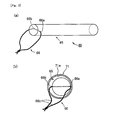
- FIG. 5(a) which is a perspective view of an endoscope excluder 60 including an the excluder body 65 in the columnar shape through which a contrast thread 66 is inserted and knotted), entering/exiting portions 66a and 66b of the inserted contrast thread 66 may be stuck in a trocar cylindrical inner wall 71a and the contrast thread 66 may be frictioned and cut off ( Fig. 5(b) which is a sectional view showing a state where the endoscope excluder 60 passes through a cylindrical portion of a trocar 71).
- the contrast thread 66 in a contrast thread portion 66c distant from the entering/exiting portions 66a and 66b of the inserted contrast thread, the contrast thread 66 can be easily prevented from being frictioned with the trocar cylindrical inner wall 71a.
- the excluder body in the bar shape is provided on each of the side surfaces with the flat portion or the concave portion so as to allow the contrast thread to be inserted therethrough.
- the cylindrical inner cavity of a trocar generally has a perfect circle shape or an elliptical shape, while a trocar in a rectangular shape is not currently used.
- the flat portion or the concave portion of the excluder body is not in contact with the inner wall surface of the trocar in such an arc shape but there is formed a gap therebetween.
- the inlet and the outlet for inserting through the contrast thread are located in the gaps. Therefore, the contrast thread is not frictioned with the cylindrical inner wall of the trocar and is thus quite unlikely to be cut off.
- Each of the inlet and the outlet for inserting through the contrast thread is preferably located at an approximate center in the thickness direction in the flat portion or the concave portion. In such a case where the inlet and the outlet are each located at the approximate center, the gap is increased in size.
- the flat portion or the concave portion needs not to be provided throughout the longitudinal length of the excluder body, but may be formed at least at one end of the excluder body in the bar shape.
- the contrast thread can be inserted, without being cut off, into a body cavity together with the excluder body. Therefore, it is possible to check whether or not the endoscope excluder remains in the body by looking for the contrast thread through radiographic visualization.
- the hygroscopically expanding material is a cellulose sponge
- an extrusion direction in a process of producing the cellulose sponge is defined to be along a Z axis and two directions perpendicular to the extrusion direction are defined to be along an X axis and a Y axis
- the contrast thread is preferably inserted through the cellulose sponge along the X axis or the Y axis(the direction intersecting with the extrusion direction in the process of producing).
- the cellulose sponge is further easily split in the extrusion direction in the production process thereof. Accordingly, if the contrast thread is inserted in the extrusion direction (along the Z axis), the cellulose sponge is likely to be split. However, when the contrast thread is inserted in the direction (along the X axis or the Y axis) intersecting with the extrusion direction as described above, the cellulose sponge is unlikely to be split.
- the cellulose sponge is compressed along the X axis in the process of producing the cellulose sponge, and the contrast thread is preferably inserted through the cellulose sponge along the X axis and knotted.
- the contrast thread is inserted in the compression directions (along the X axis) of the cellulose sponge, the length of the contrast thread passing through the cellulose sponge is increased when moisture is applied and the sponge is swollen. Accordingly, the contrast thread is further unlikely to fall off.
- the frame is preferably provided with a groove or a gap along the support wall.
- the excluder body preferably has a roentgenopaque resin attached thereto by thermal fusion bonding. More specifically, the excluder body may have, in place of the contrast thread, such a roentgenopaque resin attached thereto by thermal fusion bonding (hereinafter, this attached portion by thermal fusion bonding may be referred to as a contrast portion). It is possible to check existence of the endoscope excluder by looking for the contrast portion through radiographic visualization (X-ray photography).
- an excluder body is obtained by drying and compression molding and has a bar shape with a transverse section being smaller than a section in a cylindrical inner cavity of a trocar. Therefore, the excluder body can be inserted into a body cavity through the trocar. The excluder body is expanded in the body cavity so as to gently exclude an organ while securing a view to a target organ. Moreover, the present invention requires neither manpower for supporting the excluder nor a hole to be opened in a body of a patient in order to support the excluder.
- an excluder body can be inhibited from expanding even in a case of being exposed to moisture during the sterilization treatment, storage, or the like. Therefore, the excluder body can be kept in size so as to be inserted through the cylindrical portion of the trocar.
- the contrast thread is inserted in a flat portion or a concave portion on each of side surfaces of the excluder body. Therefore, the contrast thread is less likely to be cut off when the endoscope excluder is inserted into a body cavity through a trocar.
- the excluder 10 includes the excluder body 15 and a contrast thread 16.
- the excluder body 15 is made of a cellulose sponge and has a bar shape with a square shape in section (200 mm x 8 mm x 8 mm), of which longitudinal direction (along a Z axis) is aligned with an extrusion direction (indicated by arrows B) in a process of producing the cellulose sponge (it is noted that the longitudinal length thereof is shorter than the actual size for convenience in the figures).
- the excluder body 15 is compressed at a compressibility of 10% from side surfaces of the bar, that is, in directions (indicated by arrows A along an X axis) intersecting with the longitudinal direction (indicated by the arrows B along the Z axis).
- the excluder body 15, which is sized as described above, can be inserted through the trocar having a cylindrical inner cavity in section (in a perfect circle shape) with a diameter of 12 mm.
- viscose is obtained from a cellulosic material such as wood chips. Natural fibers are added to the viscose, and further mixed thereinto are crystallized mirabilite, a polyol compound, and a surfactant if appropriate. Sponge liquid concentrate thus obtained is extruded and filled in a mold tool to be heated and solidified. This solidified sponge is cut into a thick strip shape (200 mm x 8 mm x 80 mm) such that the extrusion direction is aligned with a longitudinal direction thereof (along the Z axis) (it is noted that the extrusion direction is aligned with the arrows B indicated in Fig.
- the contrast thread 16 is a line of thread made of a roentgenopaque resin, and specific examples thereof include a multifilament obtained by kneading barium sulfate into a polypropylene series resin, and a filum obtained by kneading barium sulfate into a vinyl chloride resin or a silicon series resin.
- the contrast thread 16 is inserted through the excluder body 15 in the bar shape near one end thereof along the compression directions (indicated by the arrows A along the X axis) and is knotted (a knotted portion 16e) into a ring shape.
- the contrast thread 16 enters and exits the excluder body 15 at centers in the thickness direction (along a Y axis) of flat portions 15e and 15f on the side surfaces.
- the contrast thread 16 is relatively long in consideration of the state where the excluder body 15 is swollen (the excluder body 15') (see Fig. 2 ).
- a patient is temporarily laid in a posture with the head located at a low position to displace the small intestine upward due to the gravity.
- the excluder 10 is inserted into the abdominal cavity through a cylindrical portion of the trocar inserted in the abdominal region from the end not provided with the contrast thread 16.
- the excluder body 15 is brought into contact with a trocar cylindrical inner wall 71a at corners 15a, 15b, 15c, and 15d, and there are formed gaps at an inlet and an outlet for the contrast thread 16 in the flat portions 15e and 15f. Accordingly, entering/exiting portions 16a and 16b of the inserted contrast thread are not frictioned with the trocar cylindrical inner wall 71a.
- portions 16c and 16d extending respectively from the entering/exiting portions 16a and 16b of the inserted contrast thread are drawn along the flat portions 15e and 16f, the portions 16c and 16d are not stuck in the trocar cylindrical inner wall 71a. Therefore, the contrast thread 16 is less likely to be cut off.
- the patient is laid in a posture with the head located at a low position only at the initial stage of the surgery unlike in a conventional surgery in which a patient needs to be laid in a posture with the head located at a low position throughout the surgery. Accordingly, the hemodynamics is not affected by the posture with the head at a low position, and a complication such as a thoracic outlet syndrome can be also prevented.
- the excluder 10 of the present invention is taken out of the body through a small incised part that is opened in the abdominal region and is used to take out the excised organ (the small incised part used for taking out the excised target organ (a small incised wound)).
- the excluder 10 is hard to be visually recognized, it is checked whether or not the excluder 10 remains in the body by looking for the contrast thread 16 to be imaged by radiographic visualization. If remaining in the body, the excluder is taken out of the body.
- the endoscope excluder is not necessarily sized so as to be inserted through the cylindrical portion of the trocar if the small incised part is formed at the initial stage of the surgery to insert the endoscope excluder into the body cavity.
- a small incised part is usually formed at the final stage of a surgery, so that it is desired to avoid the formation of the small incised part at the initial stage of the surgery only for the purpose of inserting the endoscope excluder.
- the entering/exiting portions 16a and 16b of the inserted contrast thread 16 are distant from the cylindrical inner wall of the trocar. Therefore, the contrast thread 16 is seldom frictioned to be cut off.
- the flat portions 26 and 27 are provided so as to reach one end of the excluder body 25. If the portions 16c and 16d extending respectively from the entering/exiting portions 16a and 16b of the inserted contrast thread are drawn along the flat portions 26 and 27, the portions 16c and 16d are not stuck in the cylindrical inner wall of the trocar. Therefore, the contrast thread 16 is less likely to be cut off.
- Fig. 4 is a perspective view of an endoscope excluder 30 according to a third embodiment of the present invention.
- the excluder 30 includes an excluder body 35 that has an approximately quadrangular prism shape in its entirety and has a transverse section smaller than a section of the cylindrical inner cavity of the trocar.
- the excluder body 35 is provided with concave portions 36 and 37 respectively on surfaces in the compression directions (indicated by arrows A along the X axis) in the process of manufacturing the excluder body 35.
- the contrast thread 16 is inserted through the excluder body 35 into/from an inlet and an outlet in the concave portions 36 and 37 in the vicinity of one end of the excluder body 35.
- the excluder is configured identically to that of the first embodiment in the other portions.
- the excluder 30 of the present third embodiment can be inserted into a body cavity through the trocar.
- the excluder is swollen to be increased in size in the body cavity so as to exclude an organ when physiological saline or the like is poured thereon.
- the entering/exiting portions 16a and 16b of the inserted contrast thread 16 are distant from the cylindrical inner wall of the trocar. Therefore, the contrast thread 16 is seldom frictioned to be cut off. Further, when the portions 16c and 16d extending respectively from the entering/exiting portions 16a and 16b of the inserted contrast thread are drawn so as to be away from corners of the quadrangular prism of the excluder body 35, the portions 16c and 16d are not stuck in the cylindrical inner wall of the trocar. Therefore, the contrast thread 16 is less likely to be cut off.
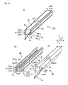
- Fig. 6(a) is a perspective view of a framed excluder 100 according to a fourth embodiment of the present invention.
- Fig. 6(c) is a perspective view of an excluder 50 in the framed excluder 100.
- Fig. 6(b) is a perspective view of a frame 40 in the framed excluder 100.
- Fig, 7 is a front view of the frame 40. It is noted that the portions denoted by the symbols same as those in Figs. 1(a) and 1(b) are constituent portions same as those of the example shown in Figs. 1(a) and 1(b) .
- the endoscope excluder 50 includes an excluder body 45 and a contrast thread 16.
- the frame 40 has a long body and includes left and right side walls 42 and 43 linearly extending in the longitudinal direction (along the Z axis) as well as a bottom wall 41.
- the frame 40 has an inner cavity configured by a main cavity 44 in a square prism shape and two sub cavities 47 and 48 that are provided continuously from the main cavity (see also Fig. 7 ).
- the sub cavities 47 and 48 are spaces in grooves formed respectively in the side walls 42 and 43 of the frame 40. More specifically, the left and right side walls 42 and 43 are provided with recesses (grooves) 42b and 43b throughout in the longitudinal direction thereof.
- the sub cavities 47 and 48 are provided in the recesses 42b and 43b, respectively.
- the main cavity 44 is formed by the bottom wall 41 and support walls 42a, 42c, 43a, and 43c (left and right side wall portions other than the recesses 42b and 43b) in the left and right side walls 42 and 43.
- the main cavity 44 is as large as 200 mm x 6 mm x 6 mm so that the excluder body 45 is tightly fit therein as shown in Fig. 6(a) .
- the entering/exiting portions 16a and 16b of the inserted contrast thread 16 are located in the sub cavities 48 and 47 that are configured by the recesses 43b and 42b in the right and left side walls 43 and 42, respectively. Moreover, the portions 16c and 16d extending from the entering/exiting portions 16a and 16b of the inserted contrast thread are also located in the sub cavities 48 and 47.
- the excluder body 45 Upon performing gas sterilization or the like, the excluder body 45 tends to be expanded in directions (indicated by arrows A' along the X axis) opposite to the compression directions by moisture generated in the treatment process.
- such expansion is suppressed by the support walls 42a and 42c and the support walls 43a and 43c facing each other, to keep the predetermined size (6 mm in width in the example shown in the figures). Expansion is suppressed also in storage even though the excluder body 45 is tends to be expanded due to moisture in the air.
- the frame 40 is opened on one of the two sides in the direction (along the Y axis) intersecting with the compression directions of the excluder body 45.
- the excluder body 45 is thus exposed to the sterilization gas on this portion. Therefore, the effect of the gas sterilization can be surely obtained.
- the excluder body 45 which is made of a cellulose sponge, is sterilized by sterilization gas (such as ethylene oxide gas) that is osmosed into the excluder body 45 in the gas sterilization treatment.
- sterilization gas such as ethylene oxide gas
- the sterilization gas flows only by way of upper and lower end surfaces (6 mm x 6 mm) of the excluder body 45 in the bar shape.
- the excluder body needs to be exposed to the sterilization gas for quite a long period of time.
- the sterilization gas is osmosed also from this open side (6 mm x 200 mm). Therefore, the sterilization gas is to reach the maximum depth of at most 6 mm, and the sterilization treatment can be surely achieved in a short period of time.
- Sterilized in the gas sterilization treatment is the entire framed excluder 100, of course inclusive of the contrast thread 16 and the frame 40.
- the gas sterilization treatment is recommended to be performed onto the framed excluder 100 that is accommodated in a package having permeability to gas.
- the framed excluder 100 is desirably supplied to a user while being accommodated in the package, so that package is opened to take the framed excluder 100 out immediately before the use thereof.
- Fig. 8 is a perspective view showing a state where the framed excluder 100 is inserted into a trocar 70.
- the remaining portions (portions from the extending portions 16c and 16d to the knotted portion 16e) of the contrast thread 16 are located behind a rear end surface (the end face at the end E provided with the contrast thread 16) of the excluder body 45. Accordingly, these remaining portions are not stuck between the excluder body 45 and the inner wall surfaces of the frame 40 (see Figs. 6(a) and 8 ).
- the frame 40 does not enter the cylindrical inner cavity 71c of the trocar because the frame 40 is larger than the cylindrical inner cavity 71c of the trocar.
- the excluder 50 thus having entered the cylindrical inner cavity 71c of the trocar 70 is inserted into a body cavity through the trocar 70, and physiological saline is poured thereon so that the excluder is swollen to exclude an organ, similarly to the first embodiment.
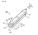
- Fig. 9 is a perspective view of a framed excluder 800 according to a fifth embodiment of the present invention. It is noted that the portions denoted by the symbols same as those in Figs. 1(a) and 1(b) are constituent portions same as those of the example shown in Figs. 1(a) and 1(b) .
- gaps 83 and 84 Between the upper member 82 and the lower member 81 in a state where these members are attached to the excluder body 15.
- the entering/exiting portions (the entering/exiting portions of the inserted contrast thread 16 with respect to the excluder body 15) of the contrast thread 16 are located in the gaps 83 and 84 so that the contrast thread 16 is not stuck.
- the excluder body 15 is expanded only in the directions opposite to the compression directions (the arrows A) of the excluder body in the manufacturing process thereof.
- the expansion of the excluder body 15 can be suppressed also in the present fifth embodiment because the frame 80 is provided with the support walls 82a, 82c, 81a, and 81c in the compression directions of the excluder body 15. Therefore, the excluder body can be kept in size so as to be inserted through the cylindrical inner cavity of the trocar.
- the gaps (opened portions) 83 and 84 are formed throughout the longitudinal length (along the Z axis) of the frame 80. Accordingly, sterilization gas is osmosed into the excluder body 15 from the gaps 83 and 84 in the gas sterilization treatment, which shortens the period of time required for the sterilization treatment.
- the end F of the framed excluder 800 not provided with the contrast thread 16 may be placed to face the insert hole of the trocar. Then, the excluder (the excluder body 15 and the contrast thread 16) may be inserted into the cylindrical portion of the trocar while being extruded in the longitudinal direction thereof (along the Z axis). In this case, the contrast thread 16 moves along the gaps 83 and 84 in the longitudinal direction so as not to be stuck or frictioned.
- the contrast portion 92 may be formed on the side surfaces 91a and 91c provided in the direction perpendicular to the compression directions (along the Y axis), instead of the side surfaces 91b and 91d to be compressed.
- the frame 93 is provided at one end in the longitudinal direction with a tongue portion 97 protruding therefrom.
- the tongue portion 97 is provided along the bottom wall 96 so as to be raised upward from the bottom wall 96 about a pin 98 serving as a rotational axis (an arrow G).
- This excluder 90 thus taken out (see Fig. 10(c) ) is inserted into a body cavity (such as a abdominal cavity or a thoracic cavity) through the cylindrical portion of the trocar.
- a body cavity such as a abdominal cavity or a thoracic cavity
- the contrast portions 92 are attached by thermal fusion bonding to the center of the side surfaces 91b and 91d of the excluder body 91 that has a rectangular shape in section, the contrast portions 92 are not frictioned with the cylindrical inner wall of the trocar. Therefore, the contrast portions 92 are quite unlikely to be frictioned to be fallen off.
- the excluder body of the present invention was tested to find out changes in size when processed by the gas sterilization treatment with use of ethylene oxide gas.
- Adopted as the excluder bodies were cellulose sponges that were obtained by drying and compression molding at a compressibility of 10% (a test sample No. 1: 200 mm x 8 mm x 8 mm, and a test sample No. 2: 200 mm x 8 mm x 6 mm).
- the test sample No. 1 prior to the compression had a size of 200 mm x 8 mm x 80 mm, while the test sample No. 2 prior to the compression had a size of 200 mm x 8 mm x 60 mm.
- the test samples Nos. 1 and 2 were compressed respectively in the thickness direction (see the arrows A indicated in Figs. 1(a) , 6(c) , and 10(c) ) into the sizes specified above.
- test results are indicated in Table 1 below.
- the fourth embodiment exemplified the frame 40 that is provided with the main cavity 44 identical in size with the width (6 mm) in the compression directions of the excluder body 45.
- the main cavity 44 in the frame 40 may be larger than the excluder body 45.
- the main cavity 44 in the frame 40 is still required not to be larger than the cylindrical inner cavity 71c of the trocar. This is because the excluder body 45 needs to be sized so as to be inserted into the cylindrical inner cavity of the trocar even in a case where the excluder body 45 is swollen enough to be in contact with the inner wall surfaces of the frame 40.
- the fourth embodiment exemplified the rectangular recesses 42b and 43b as the grooves in the side walls 42 and 43.
- these recesses may be provided as semicircular or triangular grooves.
- the frame 40 may not be provided with the bottom wall 41 (but having a frame for linking the side walls 42 and 43).
- each of the side walls of the frame is not limited to a plate body having no pore as shown in Figs. 6(a), 6(b) , and 7 to 9 as long as the side wall can prevent expansion of the excluder.
- the side wall may be a plate having a plurality of pores or a meshed plate.
- the compression directions were only aligned with the arrows A (along the X axis).
- the compression may be performed in vertical and horizontal directions (along the X axis as well as the Y axis).
- the frame is preferably provided with the side walls so as to correspond to these compression directions.
Landscapes
- Health & Medical Sciences (AREA)
- Surgery (AREA)
- Life Sciences & Earth Sciences (AREA)
- Public Health (AREA)
- Heart & Thoracic Surgery (AREA)
- Veterinary Medicine (AREA)
- Animal Behavior & Ethology (AREA)
- General Health & Medical Sciences (AREA)
- Biomedical Technology (AREA)
- Nuclear Medicine, Radiotherapy & Molecular Imaging (AREA)
- Engineering & Computer Science (AREA)
- Medical Informatics (AREA)
- Molecular Biology (AREA)
- Epidemiology (AREA)
- Vascular Medicine (AREA)
- Surgical Instruments (AREA)
- Endoscopes (AREA)
Abstract
Description
- The present invention relates to an endoscope excluder that is used for excluding an organ other than a target organ in a surgery (organ to be operated on) and is particularly suitable for use in an endoscopic surgery.
- Generally, an abdominal region or a chest region has been widely incised in a conventional surgical operation. However, due to the developments of medical technology and medical equipment, endoscopic surgeries are often executed in recent years. In such an endoscopic surgery, there are opened tiny holes at several positions in an abdominal region or the like, trocars (also called as trockars) are inserted into these holes, and a camera or a surgical instrument in an elongate shape (such as an endoscopic forceps or an endoscopic knife) are inserted through each of the trocars. The endoscopic surgeries are less invasive and apply low impact to patients.
- Similarly to laparotomy (thoracotomy, or the like), an endoscopic surgery includes excision, extirpation, or the like of an organ. Such an operation may be possibly interrupted by an organ other than a target organ (an untargeted organ) and is thus difficult to be performed. Therefore desired is that such an untargeted organ interrupting a view is excluded to secure a visual field for the target organ.
- For example, in a laparoscopic rectal surgery, because the small intestine falls into the cavity between the pelvis, the visual field for the rectum as the target organ is hard to be secured. In order to avoid such a situation, currently, the patient is laid in a posture with the head located at a low position to displace the small intestine toward a side of the head in the abdominal cavity. However, if the head is located extremely low, the hemodynamics may be affected or the brachial plexus may be excluded to possibly cause a thoracic outlet syndrome.
- In this regard, consideration has been taken on the use of an excluder in order to lay a patient horizontal as much as possible. There has been proposed an excluding instrument (excluder) for the endoscopic surgeries, which is inserted into a body cavity through a trocar and is expanded in the body cavity to exclude an untargeted organ.
- For example, Patent Document 1 describes an endoscope excluder including a rubber sheet, and a ring frame made of a super-elastic alloy and attached to surround the rubber sheet. In use thereof, this endoscope excluder is flattened out into a thin and straight shape, is inserted through a trocar, and is then expanded in width in a body cavity by a restoring force of the ring frame to exclude an organ.
- Patent Document 2 describes an excluder (a support forceps) provided with a balloon at a tip end thereof. This excluder is inserted into a body cavity through a trocar with the balloon being folded and accommodated in a cylindrical haft. The haft is then slid to expose the balloon, into which gas is injected, so that the expanded balloon excludes or supports an organ. After the use thereof, the balloon is degassed and folded to be accommodated in the cylindrical haft, and the excluder is removed from the trocar.
-
- Patent Document 1: Japanese Unexamined Patent Publication No.
2003-164459 - Patent Document 2: Japanese Unexamined Patent Publication No.
2005-253916 - However, with any one of the conventional excluders described above, a surgeon or an assistant is required to hold a grip of the excluder to keep the excluding state during the surgery, thereby additional manpower is needed. Moreover, there is another problem that an additional hole used for supporting the excluder needs to be opened in the body of a patient.
- Although each of the excluders described in Patent Documents 1 and 2 is configured to exclude an organ with use of the rubber sheet or the balloon, which are relatively soft, the frame or the haft to support the rubber sheet or the balloon is solid. In this regard, what is expected is an excluder less harmful to an organ in a body cavity.
- The present invention focused on the circumstances described above, and it is an object thereof to provide an endoscope excluder that requires neither manpower for supporting the excluder nor a hole used for supporting the excluder to be opened in a body of a patient, as well as is capable of gently excluding an organ in a body cavity.
- In accordance with an aspect of the present invention, an endoscope excluder used in an endoscopic surgery comprises an excluder body made of a hygroscopically expanding material that is obtained by drying and compression molding, wherein the excluder body has a bar shape and a transverse section smaller than a section of a cylindrical inner cavity of a trocar. It is noted that the above expression "obtained by drying and compression molding" refers to a case of compressing and drying at one time by performing compression molding while drying, as well as a case of initially compressing and then drying in such a compressed state. Hereinafter, drying and performing compression molding may be occasionally referred to as "drying and compression molding". Further, the "hygroscopically expanding material" has a property of expanding by absorption of moisture.
- As described above, in the endoscope excluder of the present invention, the excluder body has the transverse section smaller than the section of the cylindrical inner cavity of the trocar. Accordingly, the excluder can be inserted into a body cavity through the cylindrical portion of the trocar. Further, the excluder body is made of the hygroscopically expanding material obtained by drying and compression molding. Therefore, the excluder body is swollen to be increased in size when moisture is applied thereto.
- The excluder body smaller than the section of the cylindrical inner cavity of the trocar is not large enough to exclude an organ. However, if physiological saline or the like is poured on the excluder body after the endoscope excluder is inserted into a body cavity, the excluder body is swollen and increased in size so as to exclude an organ. Moreover, because the hygroscopically expanding material having been swollen has an appropriate repulsive force, an untargeted organ can be excluded by the excluder body that is made of the hygroscopically expanding material having been swollen. Furthermore, because the hygroscopically expanding material having been swollen is soft, the excluder body, which is made of the hygroscopically expanding material having been swollen, is freely bendable and easily handled, and is capable of gently excluding an untargeted organ.
- The above endoscope excluder of the present invention does not need manpower for supporting the excluder to keep the excluding state, or there is no need to provide an additional hole for the excluder in the body of a patient, unlike the endoscope excluders described in Patent Documents 1 and 2. Further, the endoscope excluder of the present invention does not have a hard frame portion, so that the swollen excluder body in the present invention is capable of gently excluding an untargeted organ.
- The "transverse section" is in a direction perpendicular to the longitudinal direction.
- The above expression "the excluder body has a transverse section smaller than a section of a cylindrical inner cavity of a trocar" specifically means that, in an exemplary case where the section of the cylindrical inner cavity of the trocar has a perfect circle shape and the excluder body has a bar shape and a section in a rectangular or square shape (the excluder body in a quadrangular prism shape), diagonal lines of the transverse section of the excluder body are shorter than a diameter of the section of the cylindrical inner cavity of the trocar. This expression "shorter" refers to a case of being substantially shorter. Even in a case where the excluder body having been dried and compressed is sized to be smaller than the section of the cylindrical inner cavity of the trocar, the excluder body may possibly absorb moisture in the air to be slightly expanded, which will result in a state where the diagonal lines of the transverse section of the excluder body are each as long as the diameter of the section of the cylindrical inner cavity of the trocar. However, even in such a case, if the excluder body is made of a slightly flexible material in a dried and compressed state, the excluder body can be inserted through the trocar while the surfaces of the excluder body are in contact with the inner wall surface of the trocar. Accordingly, such an excluder body can be still expressed as "shorter". Therefore, the present invention also includes a case where the excluder body slightly expanded is as large as the section of the cylindrical inner cavity of the trocar.
- Further, the above expression "the excluder body has a transverse section smaller than a section of a cylindrical inner cavity of a trocar" means that the transverse section at any position in the longitudinal direction of the excluder body is smaller than the section of the cylindrical inner cavity of the trocar. In other words, the excluder body does not have a portion protruding outward. Such a portion protruding outward will be stuck and inhibits the excluder body from being inserted through the trocar.
- In a laparotomy, there is a known measure of excluding an untargeted organ by displacing the organ with use of a thick sponge in a flat plate shape. This sponge excluder provided with no hard frame portion is capable of excluding an untargeted organ because the sponge itself exerts an appropriate repulsive force. Moreover, the sponge excluder is soft and is advantageously capable of excluding an untargeted organ more gently. The excluder does not need to be supported in order to keep the excluding state, which results in no need for supporting manpower. There is also proposed one of such sponge excluders for laparotomy, which is dried and compressed beforehand in order to reduce the storage space thereof, and is swollen by physiological saline or the like applied thereonto upon the use thereof.
- However, this sponge excluder for laparotomy is large (260 mm x 90 mm x 35 mm or 120 mm x 90 mm x 35 mm, for example). Accordingly, this sponge excluder cannot be inserted through the cylindrical portion of a thin trocar. However, the excluder is required to have a certain size for exclusion. No organ can be excluded by a sponge excluder that is thin enough to pass through the cylindrical portion of the trocar.
- In this regard, the endoscope excluder of the present invention, which is thin as described above, can be inserted through the cylindrical portion of the trocar. Moreover, because the excluder is sufficiently dried and compressed, the excluder can be swollen and increased in size. Therefore, an organ can be excluded by the excluder that is swollen and increased in size.
- As described above, the excluder body in the bar shape according to the present invention is obtained by drying and compression molding. In this case, the excluder body is preferably compressed at least from sides of the bar (from opposing sides intersecting with the longitudinal direction).
In other words, in the present invention, the excluder body in the bar shape has a long axis that is defined to be aligned with a Z axis, and the hygroscopically expanding material is preferably compressed in directions perpendicular to the Z axis(see an arrow A inFigs.1(a) described below, for example). In this configuration, when moisture is applied, the excluder body is swollen and expanded in the directions of the sides of the bar (in the directions of increasing the width of the bar). Therefore, even if the transverse section of the excluder body in the dried and compressed state is smaller than the cylindrical inner cavity of the trocar, the excluder body is changed into a plate shape and is capable of easily excluding an organ when being swollen after having been inserted into a body cavity. - In present invention, the endoscope excluder further comprises a long frame that accommodates the excluder body so as to be taken out thereof, wherein sides perpendicular to the compression directions of the excluder body are preferably provided with paired support walls facing each other along the Z axis. More specifically, the endoscope excluder is provided with the frame, which preferably has the support walls on the compressed surfaces of the excluder body. In the following description, such an endoscope excluder provided with a frame is referred to as a "framed excluder", while an excluder provided with no frame is simply referred to as an "endoscope excluder" or an "excluder", for the purpose of distinction therebetween.
- As described above, the excluder body is swollen and increased in size when moisture is applied thereto. Due to this property, the excluder before use may be slightly expanded by absorbing ambient moisture at the stage of sterilization treatment or storage. If the excluder body is expanded too much, the excluder body may be grown to be larger than the cylindrical inner cavity of the trocar and may not be inserted through the trocar.
- In this regard, if the excluder body is accommodated in the frame as described above, the expansion can be suppressed to keep the size of the excluder body so as to be inserted through the cylindrical inner cavity of the trocar.
- The excluder body is expanded only in the directions opposite to the compression directions during the manufacture of the excluder body. Therefore, the frame only needs to have the support walls at least on the compressed sides of the excluder body. Moreover, the support walls of the frame need not be provided entirely on the compressed sides of the excluder body, but have only to be provided to a degree of being capable of inhibiting the expansion. For example, as shown in
Fig. 6(a) , the frame may be provided with grooves at the centers of the sides corresponding to the compressed surfaces of the excluder body, so that regions above and below the grooves can support the excluder body (see left andright side walls 42 and 43 of a frame 40). - In the framed excluder, the frame preferably has an opened portion on a side other than the sides perpendicular to the compression directions.
- When the framed excluder is processed by gas sterilization, the opened portion provided as described above causes the endoscope excluder to be sufficiently exposed to sterilization gas (such as ethylene oxide gas), so that the sterilization treatment can be preferably performed. However, if the opened portion is provided on one of "the sides perpendicular to the compression directions", the excluder body may be expanded in the opened portion. Therefore, as described above, the opened portion is preferably provided on a side other than "the sides perpendicular to the compression directions".
- In the framed excluder , when two directions perpendicular to the Z axis are defined to be along an X axis and a Y axis, the excluder body is compressed along the X axis, and the frame is preferably opened at least on one side in the direction along the Y axis(the direction intersecting with the compression directions of the excluder body).
- In such a case where the frame is opened on one side in the Y axis, similarly to the above, the endoscope excluder can be sufficiently exposed to sterilization gas (such as ethylene oxide gas) to excellently perform the gas sterilization treatment.
- In view of the original purpose of preventing the expansion of the excluder body, the opened side is preferably in the direction (along the Y axis) intersecting with the compression directions (along the X axis) of the excluder body as described above. In this case, only one side in the direction along the Y axis may be opened, or both sides in the direction along the Y axis may be opened.
- In the framed excluder, the frame has a bottom wall on another side in the direction along the Y axis, and a tongue portion at least partially on an inner wall surface of the bottom wall so as to be along the inner wall surface, and the tongue portion protrudes from the bottom wall in one direction along the Z axis so as to be preferably raised toward the open side in the direction along the Y axis.
- In this framed excluder, the excluder body is accommodated in a space surrounded by the bottom wall, the tongue portion, and the support walls. The excluder body is lifted up when the tongue portion is raised. The entire excluder body may be taken out of the frame by pinching the portion lifted up with fingers. In this manner, in the above framed excluder, the excluder body accommodated in the frame can be easily taken out thereof.
- In the endoscope excluder according to the present invention, the excluder body absorbs moisture to be expanded preferably at an expansion factor of five times or more in the compression directions, and more preferably ten times or more. With such an expansion factor, the excluder body is expanded and sufficiently increased in size so as to preferably exclude an organ.
- The excluder body preferably has a compressibility of 20% or less, and more preferably 10% or less. Such a compressibility will lead to excellent expansion by the application of moisture. The compressibility (%) is calculated by "the size in the compression directions after drying and compression molding" / "the size in the same directions when manufactured without compression" x 100.
- In present invention, the hygroscopically expanding material is preferably a cellulose sponge. It is because the cellulose sponge is excellent in view of safety to a living body. Moreover, the cellulose sponge is a material that can be obtained by drying and compression molding. When moisture is applied, the dried and compressed cellulose sponge absorbs moisture to be expanded, thereby being regarded as a preferable material on this point.
- In present invention, the excluder body in the bar shape is cut so as to have a longitudinal direction(along the Z axis) thereof that is aligned with a direction of extruding the cellulose sponge in a production process thereof, and when the extrusion direction is defined to be along a Z axis and twodirection sperpendicular to the extrusion direction are defined to be along an X axis and a Y axis, the cellulose sponge is preferably compressed in the directions along the X axis and/or the Y axis.
- The cellulose sponge is generally produced by extruding a raw material from a nozzle into a mold to solidify the same. This production method is likely to cause a fiber ingredient to be aligned with the extrusion direction. Accordingly, the cellulose sponge is easily split in the extrusion direction rather than a different direction. Therefore, the excluder body in the bar shape is cut such that the extrusion direction is perpendicular to the longitudinal direction, such an excluder body in the bar shape tends to be bent and divided. In this regard, in a case where the excluder body in the bar shape is cut such that the extrusion direction is aligned with the longitudinal direction (along the Z axis), the excluder body is less likely to be split and divided.
- Moreover, the fiber ingredient in the cellulose sponge tends to be aligned with the extrusion direction in the production process as described above, the sponge can be compressed further easily in the directions (along the X axis and/or the Y axis) intersecting with the extrusion direction. The compressibility is preferably 20% or less, and more preferably 10% or less. Such a compressibility will lead to excellent expansion by the application of moisture.
- In the endoscope excluder according to the present invention, the excluder body has a contrast thread inserted therethrough and knotted, the excluder body has, on side surfaces along a longitudinal direction, two positions in total each provided with a flat portion or a concave portion, and the contrast thread is preferably inserted through the excluder body via the flat portion or the concave portion. The expression "the excluder body has a contrast thread inserted therethrough and knotted" means that the contrast thread is inserted through the excluder body and is knotted.
- As described above, the endoscope excluder according to the present invention is advantageous as requiring no manpower to support the excluder. However, this feature leads to a danger of losing the excluder in a body cavity. In a case where the inserted excluder remains in the body cavity, there are risks of causing various bad physical conditions such as pain, discomfort, and fever. Accordingly, the excluder needs to be removed from the body upon completion of a surgery. However, the excluder body having blood or the like adhering thereto is hard to be megascopically found.
- Regarding this problem, there is adopted a measure in which a hygiene material such as gauze has a contrast thread attached thereto, and radiographic visualization (X-ray photography) is performed at the final stage of the surgery to check existence of the gauze by looking for the contrast thread. In this method, the gauze is removed if remaining in the body. In this case, generally adopted as the contrast thread is a line of thread made of a roentgenopaque resin. It is noted that the sponge excluder for laparotomy described above is provided with a hole through which gauze having a strip shape and a contrast thread is inserted therethrough and attached thereto.
- Nevertheless, there still arises the following problem even if the method used for gauze is applied to the endoscope excluder. More specifically, it will be possible to attach the contrast thread by inserting through and knotting for the excluder body made of a hygroscopically expanding material that is obtained by drying and compression molding. However, as shown in
Figs. 5(a) and 5(b) for example, in a case where aexcluder body 65 has a columnar shape (Fig. 5(a) which is a perspective view of anendoscope excluder 60 including an theexcluder body 65 in the columnar shape through which acontrast thread 66 is inserted and knotted), entering/exitingportions contrast thread 66 may be stuck in a trocar cylindricalinner wall 71a and thecontrast thread 66 may be frictioned and cut off (Fig. 5(b) which is a sectional view showing a state where theendoscope excluder 60 passes through a cylindrical portion of a trocar 71). - It is noted that, in a
contrast thread portion 66c distant from the entering/exitingportions contrast thread 66 can be easily prevented from being frictioned with the trocar cylindricalinner wall 71a. - If the
endoscope excluder 60 is carefully inserted so as to pass through thetrocar 71 in the center of the cylindrical inner cavity, the entering/exitingportions inner wall 71 and thecontrast thread 66 will not be cut off. However, such a manner of insertion unrealistically requires high skill to a surgeon. - This problem is solved as described above in the present invention such that the excluder body in the bar shape is provided on each of the side surfaces with the flat portion or the concave portion so as to allow the contrast thread to be inserted therethrough. More specifically, the cylindrical inner cavity of a trocar generally has a perfect circle shape or an elliptical shape, while a trocar in a rectangular shape is not currently used. The flat portion or the concave portion of the excluder body is not in contact with the inner wall surface of the trocar in such an arc shape but there is formed a gap therebetween. In the present invention, the inlet and the outlet for inserting through the contrast thread are located in the gaps. Therefore, the contrast thread is not frictioned with the cylindrical inner wall of the trocar and is thus quite unlikely to be cut off.
- Each of the inlet and the outlet for inserting through the contrast thread is preferably located at an approximate center in the thickness direction in the flat portion or the concave portion. In such a case where the inlet and the outlet are each located at the approximate center, the gap is increased in size.
- The flat portion or the concave portion needs not to be provided throughout the longitudinal length of the excluder body, but may be formed at least at one end of the excluder body in the bar shape.
- In this manner, the contrast thread can be inserted, without being cut off, into a body cavity together with the excluder body. Therefore, it is possible to check whether or not the endoscope excluder remains in the body by looking for the contrast thread through radiographic visualization.
- In the present invention, the hygroscopically expanding material is a cellulose sponge, and when an extrusion direction in a process of producing the cellulose sponge is defined to be along a Z axis and two directions perpendicular to the extrusion direction are defined to be along an X axis and a Y axis, the contrast thread is preferably inserted through the cellulose sponge along the X axis or the Y axis(the direction intersecting with the extrusion direction in the process of producing).
- As described above, the cellulose sponge is further easily split in the extrusion direction in the production process thereof. Accordingly, if the contrast thread is inserted in the extrusion direction (along the Z axis), the cellulose sponge is likely to be split. However, when the contrast thread is inserted in the direction (along the X axis or the Y axis) intersecting with the extrusion direction as described above, the cellulose sponge is unlikely to be split.
- Moreover, in the present invention, the cellulose sponge is compressed along the X axis in the process of producing the cellulose sponge, and the contrast thread is preferably inserted through the cellulose sponge along the X axis and knotted.
- In the case where the contrast thread is inserted in the compression directions (along the X axis) of the cellulose sponge, the length of the contrast thread passing through the cellulose sponge is increased when moisture is applied and the sponge is swollen. Accordingly, the contrast thread is further unlikely to fall off.
- In the framed excluder according to the present invention, the frame is preferably provided with a groove or a gap along the support wall.
- In one possible method of using the framed excluder, the tip end of the framed excluder is placed to face the insertion hole of the trocar, the endoscope excluder in the frame (the excluder body having the contrast thread attached thereto) is pushed from the rear end so as to be extracted from the frame and inserted into the trocar (during this work, the positional relationship does not change between the frame and the trocar). In this case, there will be a risk that the contrast thread is stuck between the excluder body and the inner wall surface of the frame. However, in such a case where there is adopted the frame provided with the longitudinal groove (or the gap) as described above and the endoscope excluder is accommodated in the frame, if the groove (or the space) in the frame is located at the inlet and the outlet for the inserted contrast thread (in other words, if the contrast thread is inserted through the excluder body so as to be located at the position of the groove (or the gap)), the entering/exiting portions of the inserted contrast thread moves along the groove while the endoscope excluder is being extracted. Therefore, the contrast thread is quite unlikely to be stuck or frictioned.
- In the endoscope excluder according to the present invention, the excluder body preferably has a roentgenopaque resin attached thereto by thermal fusion bonding. More specifically, the excluder body may have, in place of the contrast thread, such a roentgenopaque resin attached thereto by thermal fusion bonding (hereinafter, this attached portion by thermal fusion bonding may be referred to as a contrast portion). It is possible to check existence of the endoscope excluder by looking for the contrast portion through radiographic visualization (X-ray photography).
- In an endoscope excluder according to the present invention, an excluder body is obtained by drying and compression molding and has a bar shape with a transverse section being smaller than a section in a cylindrical inner cavity of a trocar. Therefore, the excluder body can be inserted into a body cavity through the trocar. The excluder body is expanded in the body cavity so as to gently exclude an organ while securing a view to a target organ. Moreover, the present invention requires neither manpower for supporting the excluder nor a hole to be opened in a body of a patient in order to support the excluder.
- Further, in a framed excluder according to the present invention, an excluder body can be inhibited from expanding even in a case of being exposed to moisture during the sterilization treatment, storage, or the like. Therefore, the excluder body can be kept in size so as to be inserted through the cylindrical portion of the trocar.
- Moreover, in the present invention, in an endoscope excluder including an excluder body that has a contrast thread inserted therethrough, the contrast thread is inserted in a flat portion or a concave portion on each of side surfaces of the excluder body. Therefore, the contrast thread is less likely to be cut off when the endoscope excluder is inserted into a body cavity through a trocar.
-
-
Fig. 1(a) is a perspective view of an endoscope excluder according to a first embodiment of the present invention, andFig. 1(b) is a sectional view showing a state where the endoscope excluder passes through a cylindrical portion of a trocar in the first embodiment. -
Fig. 2 is a perspective view showing a state where an excluder body of the endoscope excluder has been swollen in the first embodiment. -
Fig. 3 is a perspective view of an endoscope excluder according to a second embodiment of the present invention. -
Fig. 4 is a perspective view of an endoscope excluder according to a third embodiment of the present invention. -
Fig. 5(a) is a perspective view of an endoscope excluder including an excluder body in a columnar shape through which a contrast thread is inserted and knotted, andFig. 5(b) is a sectional view showing a state where the endoscope excluder passes through a cylindrical portion of a trocar. -
Fig. 6(a) is a perspective view of a framed excluder according to a fourth embodiment of the present invention,Fig. 6(b) is a perspective view of such a frame, andFig. 6(c) is a perspective view of such an endoscope excluder. -
Fig. 7 is a front view of the frame according to the fourth embodiment. -
Fig. 8 is a perspective view showing a state where the framed excluder is inserted into a trocar. -
Fig. 9 is a perspective view of a framed excluder according to a fifth embodiment of the present invention. -
Fig. 10(a) is a perspective view of a framed excluder according to a sixth embodiment of the present invention,Fig. 10(b) is a perspective view of such a frame, andFig. 10(c) is a perspective view of an endoscope excluder (an excluder body and a contrast portion) therefor. -
Fig. 11 is a side view of the framed excluder according to the sixth embodiment in a state where the endoscope excluder is taken out of the frame. -
Fig. 1(a) is a perspective view of anendoscope excluder 10 according to a first embodiment of the present invention.Fig. 1(b) is a sectional view showing a state where theendoscope excluder 10 passes through a cylindrical portion of atrocar 71 in the first embodiment.Fig. 2 is a perspective view showing a state where anexcluder body 15 of theendoscope excluder 10 has been swollen (an excluder body 15') in the first embodiment. - The
excluder 10 includes theexcluder body 15 and acontrast thread 16. Theexcluder body 15 is made of a cellulose sponge and has a bar shape with a square shape in section (200 mm x 8 mm x 8 mm), of which longitudinal direction (along a Z axis) is aligned with an extrusion direction (indicated by arrows B) in a process of producing the cellulose sponge (it is noted that the longitudinal length thereof is shorter than the actual size for convenience in the figures). Theexcluder body 15 is compressed at a compressibility of 10% from side surfaces of the bar, that is, in directions (indicated by arrows A along an X axis) intersecting with the longitudinal direction (indicated by the arrows B along the Z axis). Theexcluder body 15, which is sized as described above, can be inserted through the trocar having a cylindrical inner cavity in section (in a perfect circle shape) with a diameter of 12 mm. - The cellulose sponge can be produced by adopting a cellulose regeneration method or a cellulose solvent solution method. For example, such a cellulose sponge is disclosed in Japanese Patent No.
3520511 - Specifically exemplified is a method for manufacturing the
excluder body 15. Initially, viscose is obtained from a cellulosic material such as wood chips. Natural fibers are added to the viscose, and further mixed thereinto are crystallized mirabilite, a polyol compound, and a surfactant if appropriate. Sponge liquid concentrate thus obtained is extruded and filled in a mold tool to be heated and solidified. This solidified sponge is cut into a thick strip shape (200 mm x 8 mm x 80 mm) such that the extrusion direction is aligned with a longitudinal direction thereof (along the Z axis) (it is noted that the extrusion direction is aligned with the arrows B indicated inFig. 1(a) ). This strip is dried while being compressed in directions perpendicular to the longitudinal direction (it is noted that such compression directions are aligned with the arrows A indicated inFig. 1(a) ), so as to obtain theexcluder body 15 in a thin and long bar shape (200 mm x 8 mm x 8 mm) as described above. - The
contrast thread 16 is a line of thread made of a roentgenopaque resin, and specific examples thereof include a multifilament obtained by kneading barium sulfate into a polypropylene series resin, and a filum obtained by kneading barium sulfate into a vinyl chloride resin or a silicon series resin. - The
contrast thread 16 is inserted through theexcluder body 15 in the bar shape near one end thereof along the compression directions (indicated by the arrows A along the X axis) and is knotted (a knottedportion 16e) into a ring shape. Thecontrast thread 16 enters and exits theexcluder body 15 at centers in the thickness direction (along a Y axis) offlat portions contrast thread 16 is relatively long in consideration of the state where theexcluder body 15 is swollen (the excluder body 15') (seeFig. 2 ). - Described below is a method of using the
excluder 10 according to the present first embodiment in a laparoscopic rectal surgery as an example. - A patient is temporarily laid in a posture with the head located at a low position to displace the small intestine upward due to the gravity. The
excluder 10 is inserted into the abdominal cavity through a cylindrical portion of the trocar inserted in the abdominal region from the end not provided with thecontrast thread 16. In this case, as shown inFig. 1(b) , theexcluder body 15 is brought into contact with a trocar cylindricalinner wall 71a atcorners contrast thread 16 in theflat portions portions inner wall 71a. Becauseportions portions flat portions 15e and 16f, theportions inner wall 71a. Therefore, thecontrast thread 16 is less likely to be cut off. - The
excluder body 15 is then disposed near the root of the ligament of the small intestine that was displaced upward, and physiological saline is poured thereon. As shown inFig. 2 , the compressed excluder body is swollen in directions indicated by arrows A' to be restored and increased in size (the excluder body 15', an expansion factor: ten times). The small intestine is excluded by theexcluder 10 thus swollen (approximately 200 mm x 8 mm x 80 mm), so that a view to the target organ is secured even when the posture of the patient is returned to the horizontal state. - As described above, with use of the
excluder 10 according to the present embodiment, the patient is laid in a posture with the head located at a low position only at the initial stage of the surgery unlike in a conventional surgery in which a patient needs to be laid in a posture with the head located at a low position throughout the surgery. Accordingly, the hemodynamics is not affected by the posture with the head at a low position, and a complication such as a thoracic outlet syndrome can be also prevented. - In a conventional laparoscopic surgery, the surgery is usually executed in an extreme low head posture (Trendelenburg posture) because there is no effective excluder for excluding an organ such as the small intestine out of the pelves. There is an academic report on securing a view to a target organ by nasally inserting a catheter provided at a tip end with a balloon three or four days before the surgery and handling the catheter to exclude the small intestine out of the pelves. These measures are all seriously harmful to a patient. However, the use of the
excluder 10 according to the present invention enables appropriate exclusion of an organ to secure a view without adopting any one of these measures. - When the treatment of the target organ is completed and the exclusion is no more required, the
excluder 10 of the present invention is taken out of the body through a small incised part that is opened in the abdominal region and is used to take out the excised organ (the small incised part used for taking out the excised target organ (a small incised wound)). In a case where theexcluder 10 is hard to be visually recognized, it is checked whether or not theexcluder 10 remains in the body by looking for thecontrast thread 16 to be imaged by radiographic visualization. If remaining in the body, the excluder is taken out of the body. - There may be an idea that the endoscope excluder is not necessarily sized so as to be inserted through the cylindrical portion of the trocar if the small incised part is formed at the initial stage of the surgery to insert the endoscope excluder into the body cavity. However, such a small incised part is usually formed at the final stage of a surgery, so that it is desired to avoid the formation of the small incised part at the initial stage of the surgery only for the purpose of inserting the endoscope excluder.
- As described above, in the present invention, the small incised part is used to take out the endoscope excluder, and the endoscope excluder is inserted into the body cavity through the trocar.
-
Fig. 3 is a perspective view of anendoscope excluder 20 according to a second embodiment of the present invention. - The
excluder 20 includes anexcluder body 25 that has an approximately columnar shape in its entirety and has a transverse section smaller than a section of the cylindrical inner cavity of the trocar. Theexcluder body 25 is notched from one end to a vicinity thereof so as to provideflat portions flat portions excluder body 25. In other words, the twoflat portions contrast thread 16 approximately at centers of theseflat portions - Similarly to the first embodiment, the
excluder 20 of the present second embodiment can be inserted into a body cavity through a trocar. When the excluder is swollen to be increased in size in the body cavity so as to exclude an organ when physiological saline or the like is poured thereon. - When being inserted through the trocar, the entering/exiting
portions contrast thread 16 are distant from the cylindrical inner wall of the trocar. Therefore, thecontrast thread 16 is seldom frictioned to be cut off. Further, theflat portions excluder body 25. If theportions portions flat portions portions contrast thread 16 is less likely to be cut off. -
Fig. 4 is a perspective view of anendoscope excluder 30 according to a third embodiment of the present invention. - The
excluder 30 includes anexcluder body 35 that has an approximately quadrangular prism shape in its entirety and has a transverse section smaller than a section of the cylindrical inner cavity of the trocar. Theexcluder body 35 is provided withconcave portions excluder body 35. Thecontrast thread 16 is inserted through theexcluder body 35 into/from an inlet and an outlet in theconcave portions excluder body 35. The excluder is configured identically to that of the first embodiment in the other portions. - Similarly to the first embodiment, the
excluder 30 of the present third embodiment can be inserted into a body cavity through the trocar.
The excluder is swollen to be increased in size in the body cavity so as to exclude an organ when physiological saline or the like is poured thereon. - When being inserted through the trocar, the entering/exiting
portions contrast thread 16 are distant from the cylindrical inner wall of the trocar. Therefore, thecontrast thread 16 is seldom frictioned to be cut off. Further, when theportions portions excluder body 35, theportions contrast thread 16 is less likely to be cut off. -
Fig. 6(a) is a perspective view of a framedexcluder 100 according to a fourth embodiment of the present invention.Fig. 6(c) is a perspective view of anexcluder 50 in the framedexcluder 100.Fig. 6(b) is a perspective view of aframe 40 in the framedexcluder 100.Fig, 7 is a front view of theframe 40. It is noted that the portions denoted by the symbols same as those inFigs. 1(a) and 1(b) are constituent portions same as those of the example shown inFigs. 1(a) and 1(b) . - The
endoscope excluder 50 includes anexcluder body 45 and acontrast thread 16. - As shown in
Fig. 6(c) , theexcluder body 45 in theexcluder 50 has a bar shape with a square shape in transverse section (200 mm x 6 mm x 6 mm). Thisexcluder body 45 is compressed from twoside surfaces excluder 50 is configured identically with theexcluder 10 of the first embodiment in the other portions. - As shown in
Fig. 6(b) , theframe 40 has a long body and includes left andright side walls 42 and 43 linearly extending in the longitudinal direction (along the Z axis) as well as abottom wall 41. Theframe 40 has an inner cavity configured by amain cavity 44 in a square prism shape and twosub cavities Fig. 7 ). The sub cavities 47 and 48 are spaces in grooves formed respectively in theside walls 42 and 43 of theframe 40. More specifically, the left andright side walls 42 and 43 are provided with recesses (grooves) 42b and 43b throughout in the longitudinal direction thereof. The sub cavities 47 and 48 are provided in therecesses 42b and 43b, respectively. Themain cavity 44 is formed by thebottom wall 41 andsupport walls recesses 42b and 43b) in the left andright side walls 42 and 43. Themain cavity 44 is as large as 200 mm x 6 mm x 6 mm so that theexcluder body 45 is tightly fit therein as shown inFig. 6(a) . - As shown in
Fig. 6(a) , the framedexcluder 100 includes theframe 40 and theexcluder body 45 that is accommodated in themain cavity 44 of theframe 40. Theexcluder body 45 is supported in the compression directions (indicated by the arrows A along the X axis) by thesupport walls right side walls 42 and 43 of theframe 40. Thebottom wall 41 is provided on one of the sides in the direction (along the Y axis) intersecting with the compression directions (indicated by the arrows A) of theexcluder body 45, while the other side is open. In this manner, theexcluder body 45 is exposed on one side thereof. - The entering/exiting
portions contrast thread 16 are located in thesub cavities recesses 43b and 42b in the right and leftside walls 43 and 42, respectively. Moreover, theportions portions sub cavities - Upon performing gas sterilization or the like, the
excluder body 45 tends to be expanded in directions (indicated by arrows A' along the X axis) opposite to the compression directions by moisture generated in the treatment process. However, with the framedexcluder 100 described above, such expansion is suppressed by thesupport walls support walls excluder body 45 is tends to be expanded due to moisture in the air. - As described earlier, the
frame 40 is opened on one of the two sides in the direction (along the Y axis) intersecting with the compression directions of theexcluder body 45. Theexcluder body 45 is thus exposed to the sterilization gas on this portion. Therefore, the effect of the gas sterilization can be surely obtained. - More specifically, the
excluder body 45, which is made of a cellulose sponge, is sterilized by sterilization gas (such as ethylene oxide gas) that is osmosed into theexcluder body 45 in the gas sterilization treatment. In a case where the frame surrounds the four sides of theexcluder body 45, the sterilization gas flows only by way of upper and lower end surfaces (6 mm x 6 mm) of theexcluder body 45 in the bar shape. In such a case, in order to sterilize theentire excluder body 45 in the bar shape with 200 mm in length as in the example shown in the figures, the sterilization gas is to reach the maximum depth 200 mm /2 = 100 mm. As a result, the excluder body needs to be exposed to the sterilization gas for quite a long period of time. - However, in such a case as in the fourth embodiment described above where the
frame 40 is opened one one side, the sterilization gas is osmosed also from this open side (6 mm x 200 mm). Therefore, the sterilization gas is to reach the maximum depth of at most 6 mm, and the sterilization treatment can be surely achieved in a short period of time. - Sterilized in the gas sterilization treatment is the entire framed
excluder 100, of course inclusive of thecontrast thread 16 and theframe 40. - The gas sterilization treatment is recommended to be performed onto the framed
excluder 100 that is accommodated in a package having permeability to gas. The framedexcluder 100 is desirably supplied to a user while being accommodated in the package, so that package is opened to take the framedexcluder 100 out immediately before the use thereof. - Described next is a method of using the framed
excluder 100 in an endoscopic surgery.Fig. 8 is a perspective view showing a state where the framedexcluder 100 is inserted into a trocar 70. - An end F of the framed
excluder 100 not provided with thecontrast thread 16 is placed to face aninsert hole 71b of the trocar. Theexcluder 50 is then extruded in the longitudinal direction thereof (along the Z axis) (an arrow C) from an end E provided with thecontrast thread 16 with use of a clean extrusion bar (not shown). Accordingly, theexcluder 50 is extracted from the frame 40 (an arrow D) and is inserted into a cylindricalinner cavity 71c of the trocar 70. - In this state, the entering/exiting
portions portions Fig. 6(c) ) of the insertedcontrast thread 16 of theexcluder 50 moves in thesub cavities 48 and 47 (in therecesses 43b and 42b) that are provided in the longitudinal direction (seeFig. 6(a) ). Therefore, neither the entering/exitingportions portions excluder body 45 and the inner wall surfaces of theframe 40. The remaining portions (portions from the extendingportions portion 16e) of thecontrast thread 16 are located behind a rear end surface (the end face at the end E provided with the contrast thread 16) of theexcluder body 45. Accordingly, these remaining portions are not stuck between theexcluder body 45 and the inner wall surfaces of the frame 40 (seeFigs. 6(a) and8 ). - It is noted that the
frame 40 does not enter the cylindricalinner cavity 71c of the trocar because theframe 40 is larger than the cylindricalinner cavity 71c of the trocar. - The
excluder 50 thus having entered the cylindricalinner cavity 71c of the trocar 70 is inserted into a body cavity through the trocar 70, and physiological saline is poured thereon so that the excluder is swollen to exclude an organ, similarly to the first embodiment. -
Fig. 9 is a perspective view of a framedexcluder 800 according to a fifth embodiment of the present invention. It is noted that the portions denoted by the symbols same as those inFigs. 1(a) and 1(b) are constituent portions same as those of the example shown inFigs. 1(a) and 1(b) . - The framed
excluder 800 according to the fifth embodiment includes theexcluder body 15 provided with thecontrast thread 16 and aframe 80 accommodating theexcluder body 15. Theframe 80 has anupper member 82 and alower member 81, and theupper member 82 and thelower member 81 can be separated from each other. In other words, theframe 80 can be divided into two portions along the longitudinal direction. - The
upper member 82 and thelower member 81 each have a cornered U-letter shape in section. More specifically, theupper member 82 is provided with atop surface 82b andsupport walls top surface 82b, and thelower member 81 is provided with abottom surface 81b andsupport walls bottom surface 81b. Thesupport walls upper member 82 and thesupport walls lower member 81 support theexcluder body 15 in the compression directions (arrows A along the X axis). - There are formed
gaps upper member 82 and thelower member 81 in a state where these members are attached to theexcluder body 15. The entering/exiting portions (the entering/exiting portions of the insertedcontrast thread 16 with respect to the excluder body 15) of thecontrast thread 16 are located in thegaps contrast thread 16 is not stuck. - The
excluder body 15 is expanded only in the directions opposite to the compression directions (the arrows A) of the excluder body in the manufacturing process thereof. The expansion of theexcluder body 15 can be suppressed also in the present fifth embodiment because theframe 80 is provided with thesupport walls excluder body 15. Therefore, the excluder body can be kept in size so as to be inserted through the cylindrical inner cavity of the trocar. - As described above, the gaps (opened portions) 83 and 84 are formed throughout the longitudinal length (along the Z axis) of the
frame 80. Accordingly, sterilization gas is osmosed into theexcluder body 15 from thegaps - Upon use of the framed
excluder 800 according to the fifth embodiment, theupper member 82 and thelower member 81 are separated from each other in departing directions (upward and downward directions in the figure), and the excluder (theexcluder body 15 provided with contrast thread 16) inside is taken out. The excluder is then inserted into a body cavity through the cylindrical portion of the trocar, and physiological saline is poured thereon so that the excluder is swollen to exclude an organ, as having been described earlier. - Again in the present fifth embodiment, the end F of the framed
excluder 800 not provided with thecontrast thread 16 may be placed to face the insert hole of the trocar. Then, the excluder (theexcluder body 15 and the contrast thread 16) may be inserted into the cylindrical portion of the trocar while being extruded in the longitudinal direction thereof (along the Z axis). In this case, thecontrast thread 16 moves along thegaps -
Fig. 10(a) is a perspective view of a framedexcluder 900 according to a sixth embodiment of the present invention.Fig. 10(b) is a perspective view of aframe 93 of the framedexcluder 900.Fig. 10(c) is a perspective view of an endoscope excluder 90 (anexcluder body 91 and a contrast portion 92) in the framedexcluder 900. - As shown in
Fig. 10(c) , theexcluder body 91 in theexcluder 90 has a bar shape with a square shape in transverse section (240 mm x 8 mm x 8 mm). Theexcluder body 91 has fourside surfaces side surfaces - There are provided
contrast portions 92 at centers of the side surfaces 91b and 91d in the longitudinal direction (along the Z axis) of theexcluder body 91. Thecontrast portions 92 are provided as lines of thread that are made of a roentgenopaque and thermally adhesive resin and are attached to the side surfaces 91b and 91d by thermal fusion bonding. Examples of the line of thread made of a roentgenopaque and thermally adhesive resin include a multifilament obtained by kneading barium sulfate into a polypropylene series resin, and a filum obtained by kneading barium sulfate into a vinyl chloride resin. - The
contrast portion 92 may be formed on the side surfaces 91a and 91c provided in the direction perpendicular to the compression directions (along the Y axis), instead of the side surfaces 91b and 91d to be compressed. - As shown in
Fig. 10(b) , theframe 93 has a long body, and includes abottom wall 96 and left andright side walls right side walls support walls wings support walls bottom wall 96, which is as large as tightly accommodating theexcluder body 91. - The
frame 93 is provided at one end in the longitudinal direction with atongue portion 97 protruding therefrom. Thetongue portion 97 is provided along thebottom wall 96 so as to be raised upward from thebottom wall 96 about apin 98 serving as a rotational axis (an arrow G). - As shown in
Fig. 10(a) , the framedexcluder 900 includes theframe 93 and theexcluder 90 that is accommodated in the inner cavity of theframe 93. Theexcluder 90 is supported by thesupport walls frame 93 in the compression directions (the arrows A) so as not to be expanded. - Described next is a method of using the framed
excluder 900 according to the sixth embodiment.Fig. 11 is a side view showing a state where theexcluder 90 is taken out of theframe 93. - Initially, the
tongue portion 97 of theframe 93 is raised upward (the arrow G), and one end portion of theexcluder 90 is accordingly lifted upward so as to be exposed from theframe 93. The exposed end portion is held with a hand to take theexcluder 90 out of the frame 93 (an arrow H). - This
excluder 90 thus taken out (seeFig. 10(c) ) is inserted into a body cavity (such as a abdominal cavity or a thoracic cavity) through the cylindrical portion of the trocar. In this state, because thecontrast portions 92 are attached by thermal fusion bonding to the center of the side surfaces 91b and 91d of theexcluder body 91 that has a rectangular shape in section, thecontrast portions 92 are not frictioned with the cylindrical inner wall of the trocar. Therefore, thecontrast portions 92 are quite unlikely to be frictioned to be fallen off. - Thereafter, physiological saline is poured on the
excluder 90 in the body cavity, so that theexcluder 90 is swollen and increased in size to exclude an organ. - The excluder body of the present invention was tested to find out changes in size when processed by the gas sterilization treatment with use of ethylene oxide gas.
- Adopted as the excluder bodies were cellulose sponges that were obtained by drying and compression molding at a compressibility of 10% (a test sample No. 1: 200 mm x 8 mm x 8 mm, and a test sample No. 2: 200 mm x 8 mm x 6 mm). The test sample No. 1 prior to the compression had a size of 200 mm x 8 mm x 80 mm, while the test sample No. 2 prior to the compression had a size of 200 mm x 8 mm x 60 mm. The test samples Nos. 1 and 2 were compressed respectively in the thickness direction (see the arrows A indicated in
Figs. 1(a) ,6(c) , and10(c) ) into the sizes specified above. - Three pieces of each of the test samples Nos. 1 and 2 were inserted into a sterilization bag and were processed by the ethylene oxide gas sterilization treatment. The sizes in the thickness direction of these pieces were measured after having been processed by the sterilization treatment for four and six hours. The measurements were each performed on the most expanded portion in the thickness direction. The test results are indicated in Table 1 below.
-
[Table 1] Test sample Thickness(mm) Time for sterilization (hour) Thickness after sterilization (mm) [Measuring at maximum portion] Rate of increase (%) Before compression After compression Each sample Average Each sample Average No.1 80 8 4 14.0 14.83 175.00 185.42 15.0 187.50 15.5 193.75 6 15.5 14.67 193.75 183.33 14.5 181.25 14.0 175.00 No.2 60 6 4 18.0 18.17 300.00 302.78 18.5 308.33 18.0 300.00 6 18.0 18.00 300.00 300.00 18.0 300.00 18.0 300.00 - As apparent from Table 1, each of the pieces of the test samples was expanded by the ethylene oxide gas sterilization treatment. Such expansion results in difficulty of insertion into the cylindrical portion of the trocar. However, if the sterilization treatment is applied to the excluder body that is accommodated in the frame, such expansion can be suppressed. Consequently, it is effective to provide such a framed excluder.
- The excluder as well as the framed excluder according to the present invention have been specifically described with reference to the exemplary drawings. However, the present invention should not be limited to the illustrated examples, and can be embodied with appropriate modifications as long as being applicable to the purposes of the invention. Such modifications are all included in the technical scope of the present invention.
- For example, the fourth embodiment exemplified the
frame 40 that is provided with themain cavity 44 identical in size with the width (6 mm) in the compression directions of theexcluder body 45. Alternatively, themain cavity 44 in theframe 40 may be larger than theexcluder body 45. Even in such a case, themain cavity 44 in theframe 40 is still required not to be larger than the cylindricalinner cavity 71c of the trocar. This is because theexcluder body 45 needs to be sized so as to be inserted into the cylindrical inner cavity of the trocar even in a case where theexcluder body 45 is swollen enough to be in contact with the inner wall surfaces of theframe 40. - Further, the fourth embodiment exemplified the
rectangular recesses 42b and 43b as the grooves in theside walls 42 and 43. Alternatively, these recesses may be provided as semicircular or triangular grooves. - Moreover, in the fourth embodiment, the
frame 40 may not be provided with the bottom wall 41 (but having a frame for linking the side walls 42 and 43). - The fourth embodiment exemplified the
frame 40 that has the grooves (therecesses 42b and 43b) in theside walls 42 and 43. Alternatively, the frame may not be provided with the grooves in a case where adopted is an excluder having a contrast thread that does not pass through the side surfaces of an excluder body (such as an excluder having a contrast thread passing through the axis of an excluder body in a bar shape, an excluder having a contrast thread that is attached to a side surface of an excluder body by thermal fusion bonding, or an excluder having an RFID tag in place of a contrast thread attached to an excluder body in order to prevent such a contrast thread from remaining) (in the sixth embodiment, for example). - Furthermore, each of the side walls of the frame is not limited to a plate body having no pore as shown in
Figs. 6(a), 6(b) , and7 to 9 as long as the side wall can prevent expansion of the excluder. For example, the side wall may be a plate having a plurality of pores or a meshed plate. - In each of the first to sixth embodiments described above, the compression directions were only aligned with the arrows A (along the X axis). Alternatively, the compression may be performed in vertical and horizontal directions (along the X axis as well as the Y axis). In this case, the frame is preferably provided with the side walls so as to correspond to these compression directions.
-
- 10, 20, 30, 50, 90
- endoscope excluder
- 15, 25, 35, 45, 91
- excluder body
- 15e, 15f, 26, 27
- flat portion
- 16
- contrast thread
- 16a, 16b
- entering/exiting portion of inserted contrast thread
- 36, 37
- concave portion
- 40, 80, 93
- frame
- 41, 42, 43, 94, 95
- side wall
- 42a, 42c, 43a, 43c, 81a, 81c, 82a, 82c, 94a, 95a
- support wall
- 42b, 43b
- recess (groove)
- 44
- main cavity
- 47, 48
- sub cavity
- 70
- trocar
- 71a
- trocar cylindrical inner wall
- 92
- contrast portion
- 97
- tongue portion
- 98
- pin
- 100, 800, 900
- framed excluder
Claims (14)
- An endoscope excluder used in an endoscopic surgery, comprising:an excluder body made of a hygroscopically expanding material that is obtained by drying and compression molding, whereinthe excluder body has a bar shape and a transverse section smaller than a section of a cylindrical inner cavity of a trocar.
- The endoscope excluder according to claim 1, wherein
the excluder body in the bar shape has a long axis that is defined to be aligned with a Z axis, and the hygroscopically expanding material is compressed in directions perpendicular to the Z axis. - The endoscope excluder according to claim 1 or 2, further comprising:a long frame that accommodates the excluder body so as to be taken out thereof, whereinsides perpendicular to the compression directions of the excluder body are provided with paired support walls facing each other along the Z axis.
- The endoscope excluder according to claim 3, wherein
the frame has an opened portion on a side other than the sides perpendicular to the compression directions. - The endoscope excluder according to claim 3, wherein
when two directions perpendicular to the Z axis are defined to be along an X axis and a Y axis,
the excluder body is compressed along the X axis, and the frame is opened at least on one side in the direction along the Y axis. - The endoscope excluder according to claim 5, wherein
the frame has a bottom wall on another side in the direction along the Y axis, and a tongue portion at least partially on an inner wall surface of the bottom wall so as to be along the inner wall surface, and
the tongue portion protrudes from the bottom wall in one direction along the Z axis so as to be raised toward the open side in the direction along the Y axis. - The endoscope excluder according to any one of claims 1 to 6, wherein
the excluder body absorbs moisture to be expanded at an expansion factor of five times or more in the compression directions. - The endoscope excluder according to any one of claims 1 to 7, wherein
the hygroscopically expanding material is a cellulose sponge. - The endoscope excluder according to claim 8, wherein
the excluder body in the bar shape is cut so as to have a longitudinal direction thereof that is aligned with a direction of extruding the cellulose sponge in a production process thereof, and
when the extrusion direction is defined to be along a Z axis and two directions perpendicular to the extrusion direction are defined to be along an X axis and a Y axis, the cellulose sponge is compressed in the directions along the X axis and/or the Y axis. - The endoscope excluder according to any one of claims 1 to 9, wherein
the excluder body has a roentgenopaque resin attached thereto by thermal fusion bonding. - The endoscope excluder according to any one of claims 1 to 9, wherein
the excluder body has a contrast thread inserted therethrough and knotted,
the excluder body has, on side surfaces along a longitudinal direction, two positions in total each provided with a flat portion or a concave portion, and the contrast thread is inserted through the excluder body via the flat portion or the concave portion. - The endoscope excluder according to claim 11, wherein
the hygroscopically expanding material is a cellulose sponge, and when an extrusion direction in a process of producing the cellulose sponge is defined to be along a Z axis and two directions perpendicular to the extrusion direction are defined to be along an X axis and a Y axis, the contrast thread is inserted through the cellulose sponge along the X axis or the Y axis. - The endoscope excluder according to claim 12, wherein
the cellulose sponge is compressed along the X axis in the process of producing the cellulose sponge, and the contrast thread is inserted through the cellulose sponge along the X axis and knotted. - The endoscope excluder according to any one of claims 11 to 13, wherein
the frame is provided with a groove or a gap along the support wall.
Applications Claiming Priority (2)
| Application Number | Priority Date | Filing Date | Title |
|---|---|---|---|
| JP2008223986 | 2008-09-01 | ||
| PCT/JP2009/064777 WO2010024244A1 (en) | 2008-09-01 | 2009-08-25 | Endoscope excluder |
Publications (3)
| Publication Number | Publication Date |
|---|---|
| EP2332469A1 true EP2332469A1 (en) | 2011-06-15 |
| EP2332469A4 EP2332469A4 (en) | 2011-09-28 |
| EP2332469B1 EP2332469B1 (en) | 2015-05-27 |
Family
ID=41721412
Family Applications (1)
| Application Number | Title | Priority Date | Filing Date |
|---|---|---|---|
| EP09809895.7A Active EP2332469B1 (en) | 2008-09-01 | 2009-08-25 | Endoscope excluder |
Country Status (5)
| Country | Link |
|---|---|
| EP (1) | EP2332469B1 (en) |
| JP (1) | JP5128672B2 (en) |
| KR (1) | KR101353192B1 (en) |
| ES (1) | ES2544825T3 (en) |
| WO (1) | WO2010024244A1 (en) |
Cited By (1)
| Publication number | Priority date | Publication date | Assignee | Title |
|---|---|---|---|---|
| EP2545858A4 (en) * | 2010-03-08 | 2015-06-24 | Kawamoto Corp | Surgical retractor |
Families Citing this family (4)
| Publication number | Priority date | Publication date | Assignee | Title |
|---|---|---|---|---|
| JP5739660B2 (en) * | 2010-12-27 | 2015-06-24 | オオサキメディカル株式会社 | Exclusion body for endoscopic surgery |
| JP2012152236A (en) * | 2011-01-21 | 2012-08-16 | Kawamoto Sangyo Kk | Spacer |
| JP5674545B2 (en) * | 2011-04-22 | 2015-02-25 | オオサキメディカル株式会社 | Liver lifting pressure relief device |
| KR20170007725A (en) | 2014-05-19 | 2017-01-20 | 도오레 화인케미칼 가부시키가이샤 | Excluder |
Family Cites Families (11)
| Publication number | Priority date | Publication date | Assignee | Title |
|---|---|---|---|---|
| US3961629A (en) * | 1968-06-11 | 1976-06-08 | American Cyanamid Company | Using hydrophilic polyurethane laparotomy sponges |
| US6120437A (en) * | 1988-07-22 | 2000-09-19 | Inbae Yoon | Methods for creating spaces at obstructed sites endoscopically and methods therefor |
| US5074840A (en) * | 1990-07-24 | 1991-12-24 | Inbae Yoon | Packing device and method of packing for endoscopic procedures |
| US5374261A (en) * | 1990-07-24 | 1994-12-20 | Yoon; Inbae | Multifunctional devices for use in endoscopic surgical procedures and methods-therefor |
| JPH07116262A (en) * | 1993-10-22 | 1995-05-09 | Olympus Optical Co Ltd | Expanding body for medical treatment |
| US5466231A (en) * | 1993-11-04 | 1995-11-14 | Merocel Corporation | Laminated sponge device |
| JP3520511B2 (en) | 2000-09-04 | 2004-04-19 | 株式会社ホギメディカル | Method for producing wound-absorbent covering protective material using cellulose sponge |
| JP4033327B2 (en) | 2001-11-30 | 2008-01-16 | 株式会社八光 | Retractor |
| JP2005253916A (en) | 2004-03-10 | 2005-09-22 | Shigehisa Yanagimoto | Balloon type supporting forceps using carbon dioxide injection for abdominal surgery with small visual field such as laparoscopy, extrasomatic method or the like |
| JP4995811B2 (en) * | 2005-04-29 | 2012-08-08 | クック・バイオテック・インコーポレーテッド | Acupuncture positive displacement implants and related methods and systems |
| JP2009089900A (en) * | 2007-10-09 | 2009-04-30 | Toray Fine Chemicals Co Ltd | Member for exclusion in surgery |
-
2009
- 2009-08-25 JP JP2010526715A patent/JP5128672B2/en active Active
- 2009-08-25 WO PCT/JP2009/064777 patent/WO2010024244A1/en not_active Ceased
- 2009-08-25 ES ES09809895.7T patent/ES2544825T3/en active Active
- 2009-08-25 KR KR1020117004683A patent/KR101353192B1/en not_active Expired - Fee Related
- 2009-08-25 EP EP09809895.7A patent/EP2332469B1/en active Active
Cited By (1)
| Publication number | Priority date | Publication date | Assignee | Title |
|---|---|---|---|---|
| EP2545858A4 (en) * | 2010-03-08 | 2015-06-24 | Kawamoto Corp | Surgical retractor |
Also Published As
| Publication number | Publication date |
|---|---|
| JP5128672B2 (en) | 2013-01-23 |
| ES2544825T3 (en) | 2015-09-04 |
| EP2332469A4 (en) | 2011-09-28 |
| EP2332469B1 (en) | 2015-05-27 |
| KR20110053229A (en) | 2011-05-19 |
| JPWO2010024244A1 (en) | 2012-01-26 |
| KR101353192B1 (en) | 2014-01-17 |
| WO2010024244A1 (en) | 2010-03-04 |
Similar Documents
| Publication | Publication Date | Title |
|---|---|---|
| US8137322B2 (en) | Stabilization assist device for trocar | |
| EP2332469B1 (en) | Endoscope excluder | |
| US20130085339A1 (en) | Surgical retractor | |
| JP2010207575A (en) | Access point including multi-layer seal and suture park | |
| US20140031616A1 (en) | Non-fibrous barrier for organ retention | |
| US20060252997A1 (en) | Medical port device, kit and associated method | |
| KR20100110844A (en) | Organ spacer for scope-assisted surgery | |
| JP2002360582A (en) | Internal organ exclusion tool | |
| KR102481857B1 (en) | Hemostatic pad insertion device for laparoscopic surgery, and circularly wound hemostatic pad used therefor | |
| CN219940714U (en) | Vertebral plate rongeur with aspirator function | |
| EP3146906A1 (en) | Excluder | |
| WO2012178039A1 (en) | Non-fibrous barrier for organ retention | |
| JP4706015B2 (en) | Disposable fabric inserter | |
| KR102459763B1 (en) | Hemostatic pad wound in circular shape, and device for inserting the same into the human body | |
| KR102557039B1 (en) | Hemostatic pad insertion device for laparoscopic surgery | |
| JP5313394B2 (en) | Surgical exclusion body | |
| CA3065879A1 (en) | Access assembly including flexible cannula | |
| US20240216014A1 (en) | Flexible Surgical Halo | |
| JP4297710B2 (en) | Exclusion device | |
| CN209751123U (en) | Pneumoperitoneum reconstruction device | |
| US20120083659A1 (en) | Foam Surgical Retractor | |
| CN112773954A (en) | Drainage strip | |
| JP2006095096A (en) | Tissue closing implement in vivo and tissue closing device in vivo | |
| Colakhodzic et al. | Design of a Tunneling System for Endoscopic Neurosurgery | |
| JP2010029491A (en) | Endoscope hood and diagnosis-treatment method using endoscope hood |
Legal Events
| Date | Code | Title | Description |
|---|---|---|---|
| PUAI | Public reference made under article 153(3) epc to a published international application that has entered the european phase |
Free format text: ORIGINAL CODE: 0009012 |
|
| 17P | Request for examination filed |
Effective date: 20110331 |
|
| AK | Designated contracting states |
Kind code of ref document: A1 Designated state(s): AT BE BG CH CY CZ DE DK EE ES FI FR GB GR HR HU IE IS IT LI LT LU LV MC MK MT NL NO PL PT RO SE SI SK SM TR |
|
| AX | Request for extension of the european patent |
Extension state: AL BA RS |
|
| A4 | Supplementary search report drawn up and despatched |
Effective date: 20110825 |
|
| RIC1 | Information provided on ipc code assigned before grant |
Ipc: A61L 31/00 20060101ALI20110819BHEP Ipc: A61B 17/02 20060101AFI20110819BHEP Ipc: A61B 17/00 20060101ALI20110819BHEP |
|
| DAX | Request for extension of the european patent (deleted) | ||
| 17Q | First examination report despatched |
Effective date: 20120806 |
|
| GRAP | Despatch of communication of intention to grant a patent |
Free format text: ORIGINAL CODE: EPIDOSNIGR1 |
|
| INTG | Intention to grant announced |
Effective date: 20141209 |
|
| GRAS | Grant fee paid |
Free format text: ORIGINAL CODE: EPIDOSNIGR3 |
|
| GRAA | (expected) grant |
Free format text: ORIGINAL CODE: 0009210 |
|
| AK | Designated contracting states |
Kind code of ref document: B1 Designated state(s): AT BE BG CH CY CZ DE DK EE ES FI FR GB GR HR HU IE IS IT LI LT LU LV MC MK MT NL NO PL PT RO SE SI SK SM TR |
|
| REG | Reference to a national code |
Ref country code: GB Ref legal event code: FG4D |
|
| REG | Reference to a national code |
Ref country code: CH Ref legal event code: EP |
|
| REG | Reference to a national code |
Ref country code: AT Ref legal event code: REF Ref document number: 728398 Country of ref document: AT Kind code of ref document: T Effective date: 20150615 |
|
| REG | Reference to a national code |
Ref country code: IE Ref legal event code: FG4D |
|
| REG | Reference to a national code |
Ref country code: DE Ref legal event code: R096 Ref document number: 602009031475 Country of ref document: DE |
|
| REG | Reference to a national code |
Ref country code: ES Ref legal event code: FG2A Ref document number: 2544825 Country of ref document: ES Kind code of ref document: T3 Effective date: 20150904 |
|
| REG | Reference to a national code |
Ref country code: AT Ref legal event code: MK05 Ref document number: 728398 Country of ref document: AT Kind code of ref document: T Effective date: 20150527 |
|
| REG | Reference to a national code |
Ref country code: LT Ref legal event code: MG4D |
|
| PG25 | Lapsed in a contracting state [announced via postgrant information from national office to epo] |
Ref country code: HR Free format text: LAPSE BECAUSE OF FAILURE TO SUBMIT A TRANSLATION OF THE DESCRIPTION OR TO PAY THE FEE WITHIN THE PRESCRIBED TIME-LIMIT Effective date: 20150527 Ref country code: PT Free format text: LAPSE BECAUSE OF FAILURE TO SUBMIT A TRANSLATION OF THE DESCRIPTION OR TO PAY THE FEE WITHIN THE PRESCRIBED TIME-LIMIT Effective date: 20150928 Ref country code: LT Free format text: LAPSE BECAUSE OF FAILURE TO SUBMIT A TRANSLATION OF THE DESCRIPTION OR TO PAY THE FEE WITHIN THE PRESCRIBED TIME-LIMIT Effective date: 20150527 Ref country code: NO Free format text: LAPSE BECAUSE OF FAILURE TO SUBMIT A TRANSLATION OF THE DESCRIPTION OR TO PAY THE FEE WITHIN THE PRESCRIBED TIME-LIMIT Effective date: 20150827 Ref country code: FI Free format text: LAPSE BECAUSE OF FAILURE TO SUBMIT A TRANSLATION OF THE DESCRIPTION OR TO PAY THE FEE WITHIN THE PRESCRIBED TIME-LIMIT Effective date: 20150527 |
|
| PG25 | Lapsed in a contracting state [announced via postgrant information from national office to epo] |
Ref country code: IS Free format text: LAPSE BECAUSE OF FAILURE TO SUBMIT A TRANSLATION OF THE DESCRIPTION OR TO PAY THE FEE WITHIN THE PRESCRIBED TIME-LIMIT Effective date: 20150927 Ref country code: AT Free format text: LAPSE BECAUSE OF FAILURE TO SUBMIT A TRANSLATION OF THE DESCRIPTION OR TO PAY THE FEE WITHIN THE PRESCRIBED TIME-LIMIT Effective date: 20150527 Ref country code: BG Free format text: LAPSE BECAUSE OF FAILURE TO SUBMIT A TRANSLATION OF THE DESCRIPTION OR TO PAY THE FEE WITHIN THE PRESCRIBED TIME-LIMIT Effective date: 20150827 Ref country code: GR Free format text: LAPSE BECAUSE OF FAILURE TO SUBMIT A TRANSLATION OF THE DESCRIPTION OR TO PAY THE FEE WITHIN THE PRESCRIBED TIME-LIMIT Effective date: 20150828 Ref country code: LV Free format text: LAPSE BECAUSE OF FAILURE TO SUBMIT A TRANSLATION OF THE DESCRIPTION OR TO PAY THE FEE WITHIN THE PRESCRIBED TIME-LIMIT Effective date: 20150527 |
|
| PG25 | Lapsed in a contracting state [announced via postgrant information from national office to epo] |
Ref country code: DK Free format text: LAPSE BECAUSE OF FAILURE TO SUBMIT A TRANSLATION OF THE DESCRIPTION OR TO PAY THE FEE WITHIN THE PRESCRIBED TIME-LIMIT Effective date: 20150527 Ref country code: EE Free format text: LAPSE BECAUSE OF FAILURE TO SUBMIT A TRANSLATION OF THE DESCRIPTION OR TO PAY THE FEE WITHIN THE PRESCRIBED TIME-LIMIT Effective date: 20150527 |
|
| PG25 | Lapsed in a contracting state [announced via postgrant information from national office to epo] |
Ref country code: CZ Free format text: LAPSE BECAUSE OF FAILURE TO SUBMIT A TRANSLATION OF THE DESCRIPTION OR TO PAY THE FEE WITHIN THE PRESCRIBED TIME-LIMIT Effective date: 20150527 Ref country code: SK Free format text: LAPSE BECAUSE OF FAILURE TO SUBMIT A TRANSLATION OF THE DESCRIPTION OR TO PAY THE FEE WITHIN THE PRESCRIBED TIME-LIMIT Effective date: 20150527 Ref country code: RO Free format text: LAPSE BECAUSE OF NON-PAYMENT OF DUE FEES Effective date: 20150527 Ref country code: PL Free format text: LAPSE BECAUSE OF FAILURE TO SUBMIT A TRANSLATION OF THE DESCRIPTION OR TO PAY THE FEE WITHIN THE PRESCRIBED TIME-LIMIT Effective date: 20150527 |
|
| REG | Reference to a national code |
Ref country code: DE Ref legal event code: R097 Ref document number: 602009031475 Country of ref document: DE |
|
| PG25 | Lapsed in a contracting state [announced via postgrant information from national office to epo] |
Ref country code: LU Free format text: LAPSE BECAUSE OF FAILURE TO SUBMIT A TRANSLATION OF THE DESCRIPTION OR TO PAY THE FEE WITHIN THE PRESCRIBED TIME-LIMIT Effective date: 20150825 Ref country code: MC Free format text: LAPSE BECAUSE OF FAILURE TO SUBMIT A TRANSLATION OF THE DESCRIPTION OR TO PAY THE FEE WITHIN THE PRESCRIBED TIME-LIMIT Effective date: 20150527 |
|
| REG | Reference to a national code |
Ref country code: CH Ref legal event code: PL |
|
| PLBE | No opposition filed within time limit |
Free format text: ORIGINAL CODE: 0009261 |
|
| STAA | Information on the status of an ep patent application or granted ep patent |
Free format text: STATUS: NO OPPOSITION FILED WITHIN TIME LIMIT |
|
| PG25 | Lapsed in a contracting state [announced via postgrant information from national office to epo] |
Ref country code: LI Free format text: LAPSE BECAUSE OF NON-PAYMENT OF DUE FEES Effective date: 20150831 Ref country code: CH Free format text: LAPSE BECAUSE OF NON-PAYMENT OF DUE FEES Effective date: 20150831 |
|
| 26N | No opposition filed |
Effective date: 20160301 |
|
| PG25 | Lapsed in a contracting state [announced via postgrant information from national office to epo] |
Ref country code: SI Free format text: LAPSE BECAUSE OF FAILURE TO SUBMIT A TRANSLATION OF THE DESCRIPTION OR TO PAY THE FEE WITHIN THE PRESCRIBED TIME-LIMIT Effective date: 20150527 |
|
| REG | Reference to a national code |
Ref country code: IE Ref legal event code: MM4A |
|
| PG25 | Lapsed in a contracting state [announced via postgrant information from national office to epo] |
Ref country code: IE Free format text: LAPSE BECAUSE OF NON-PAYMENT OF DUE FEES Effective date: 20150825 |
|
| REG | Reference to a national code |
Ref country code: FR Ref legal event code: PLFP Year of fee payment: 8 |
|
| PG25 | Lapsed in a contracting state [announced via postgrant information from national office to epo] |
Ref country code: BE Free format text: LAPSE BECAUSE OF FAILURE TO SUBMIT A TRANSLATION OF THE DESCRIPTION OR TO PAY THE FEE WITHIN THE PRESCRIBED TIME-LIMIT Effective date: 20150527 |
|
| PG25 | Lapsed in a contracting state [announced via postgrant information from national office to epo] |
Ref country code: MT Free format text: LAPSE BECAUSE OF FAILURE TO SUBMIT A TRANSLATION OF THE DESCRIPTION OR TO PAY THE FEE WITHIN THE PRESCRIBED TIME-LIMIT Effective date: 20150527 |
|
| PG25 | Lapsed in a contracting state [announced via postgrant information from national office to epo] |
Ref country code: SM Free format text: LAPSE BECAUSE OF FAILURE TO SUBMIT A TRANSLATION OF THE DESCRIPTION OR TO PAY THE FEE WITHIN THE PRESCRIBED TIME-LIMIT Effective date: 20150527 Ref country code: HU Free format text: LAPSE BECAUSE OF FAILURE TO SUBMIT A TRANSLATION OF THE DESCRIPTION OR TO PAY THE FEE WITHIN THE PRESCRIBED TIME-LIMIT; INVALID AB INITIO Effective date: 20090825 |
|
| PG25 | Lapsed in a contracting state [announced via postgrant information from national office to epo] |
Ref country code: SE Free format text: LAPSE BECAUSE OF FAILURE TO SUBMIT A TRANSLATION OF THE DESCRIPTION OR TO PAY THE FEE WITHIN THE PRESCRIBED TIME-LIMIT Effective date: 20150527 Ref country code: CY Free format text: LAPSE BECAUSE OF FAILURE TO SUBMIT A TRANSLATION OF THE DESCRIPTION OR TO PAY THE FEE WITHIN THE PRESCRIBED TIME-LIMIT Effective date: 20150527 |
|
| REG | Reference to a national code |
Ref country code: FR Ref legal event code: PLFP Year of fee payment: 9 |
|
| PG25 | Lapsed in a contracting state [announced via postgrant information from national office to epo] |
Ref country code: MK Free format text: LAPSE BECAUSE OF FAILURE TO SUBMIT A TRANSLATION OF THE DESCRIPTION OR TO PAY THE FEE WITHIN THE PRESCRIBED TIME-LIMIT Effective date: 20150527 |
|
| REG | Reference to a national code |
Ref country code: FR Ref legal event code: PLFP Year of fee payment: 10 |
|
| PGFP | Annual fee paid to national office [announced via postgrant information from national office to epo] |
Ref country code: TR Payment date: 20230817 Year of fee payment: 15 Ref country code: GB Payment date: 20230824 Year of fee payment: 15 |
|
| PGFP | Annual fee paid to national office [announced via postgrant information from national office to epo] |
Ref country code: FR Payment date: 20230824 Year of fee payment: 15 |
|
| GBPC | Gb: european patent ceased through non-payment of renewal fee |
Effective date: 20240825 |
|
| PG25 | Lapsed in a contracting state [announced via postgrant information from national office to epo] |
Ref country code: GB Free format text: LAPSE BECAUSE OF NON-PAYMENT OF DUE FEES Effective date: 20240825 |
|
| PG25 | Lapsed in a contracting state [announced via postgrant information from national office to epo] |
Ref country code: FR Free format text: LAPSE BECAUSE OF NON-PAYMENT OF DUE FEES Effective date: 20240831 |
|
| PGFP | Annual fee paid to national office [announced via postgrant information from national office to epo] |
Ref country code: NL Payment date: 20250821 Year of fee payment: 17 |
|
| PGFP | Annual fee paid to national office [announced via postgrant information from national office to epo] |
Ref country code: ES Payment date: 20250917 Year of fee payment: 17 |
|
| PGFP | Annual fee paid to national office [announced via postgrant information from national office to epo] |
Ref country code: DE Payment date: 20250827 Year of fee payment: 17 |
|
| PGFP | Annual fee paid to national office [announced via postgrant information from national office to epo] |
Ref country code: IT Payment date: 20250829 Year of fee payment: 17 |