EP2332017B1 - Estimating a state of at least one target - Google Patents
Estimating a state of at least one target Download PDFInfo
- Publication number
- EP2332017B1 EP2332017B1 EP09785562.1A EP09785562A EP2332017B1 EP 2332017 B1 EP2332017 B1 EP 2332017B1 EP 09785562 A EP09785562 A EP 09785562A EP 2332017 B1 EP2332017 B1 EP 2332017B1
- Authority
- EP
- European Patent Office
- Prior art keywords
- measurement
- sensor
- target
- target measurement
- regression model
- Prior art date
- Legal status (The legal status is an assumption and is not a legal conclusion. Google has not performed a legal analysis and makes no representation as to the accuracy of the status listed.)
- Active
Links
- 238000005259 measurement Methods 0.000 claims description 97
- 238000000034 method Methods 0.000 claims description 73
- 238000012549 training Methods 0.000 claims description 23
- 230000004927 fusion Effects 0.000 claims description 14
- 239000011159 matrix material Substances 0.000 claims description 9
- 238000004590 computer program Methods 0.000 claims description 4
- 238000004422 calculation algorithm Methods 0.000 description 8
- 238000007499 fusion processing Methods 0.000 description 7
- 230000006870 function Effects 0.000 description 5
- 238000012937 correction Methods 0.000 description 3
- 238000013528 artificial neural network Methods 0.000 description 2
- 230000007613 environmental effect Effects 0.000 description 2
- 230000009897 systematic effect Effects 0.000 description 2
- 230000002411 adverse Effects 0.000 description 1
- 238000013459 approach Methods 0.000 description 1
- 238000013476 bayesian approach Methods 0.000 description 1
- 230000015556 catabolic process Effects 0.000 description 1
- 238000000354 decomposition reaction Methods 0.000 description 1
- 238000006731 degradation reaction Methods 0.000 description 1
- 238000010586 diagram Methods 0.000 description 1
- 230000000694 effects Effects 0.000 description 1
- 238000005516 engineering process Methods 0.000 description 1
- 238000002474 experimental method Methods 0.000 description 1
- 238000009499 grossing Methods 0.000 description 1
- 238000010801 machine learning Methods 0.000 description 1
- 238000012544 monitoring process Methods 0.000 description 1
- 238000005457 optimization Methods 0.000 description 1
- 230000035755 proliferation Effects 0.000 description 1
- 238000005295 random walk Methods 0.000 description 1
- 238000004088 simulation Methods 0.000 description 1
Images


Classifications
-
- G—PHYSICS
- G01—MEASURING; TESTING
- G01S—RADIO DIRECTION-FINDING; RADIO NAVIGATION; DETERMINING DISTANCE OR VELOCITY BY USE OF RADIO WAVES; LOCATING OR PRESENCE-DETECTING BY USE OF THE REFLECTION OR RERADIATION OF RADIO WAVES; ANALOGOUS ARRANGEMENTS USING OTHER WAVES
- G01S7/00—Details of systems according to groups G01S13/00, G01S15/00, G01S17/00
- G01S7/003—Transmission of data between radar, sonar or lidar systems and remote stations
-
- G—PHYSICS
- G01—MEASURING; TESTING
- G01S—RADIO DIRECTION-FINDING; RADIO NAVIGATION; DETERMINING DISTANCE OR VELOCITY BY USE OF RADIO WAVES; LOCATING OR PRESENCE-DETECTING BY USE OF THE REFLECTION OR RERADIATION OF RADIO WAVES; ANALOGOUS ARRANGEMENTS USING OTHER WAVES
- G01S13/00—Systems using the reflection or reradiation of radio waves, e.g. radar systems; Analogous systems using reflection or reradiation of waves whose nature or wavelength is irrelevant or unspecified
- G01S13/66—Radar-tracking systems; Analogous systems
- G01S13/72—Radar-tracking systems; Analogous systems for two-dimensional tracking, e.g. combination of angle and range tracking, track-while-scan radar
- G01S13/723—Radar-tracking systems; Analogous systems for two-dimensional tracking, e.g. combination of angle and range tracking, track-while-scan radar by using numerical data
- G01S13/726—Multiple target tracking
-
- G—PHYSICS
- G01—MEASURING; TESTING
- G01S—RADIO DIRECTION-FINDING; RADIO NAVIGATION; DETERMINING DISTANCE OR VELOCITY BY USE OF RADIO WAVES; LOCATING OR PRESENCE-DETECTING BY USE OF THE REFLECTION OR RERADIATION OF RADIO WAVES; ANALOGOUS ARRANGEMENTS USING OTHER WAVES
- G01S13/00—Systems using the reflection or reradiation of radio waves, e.g. radar systems; Analogous systems using reflection or reradiation of waves whose nature or wavelength is irrelevant or unspecified
- G01S13/86—Combinations of radar systems with non-radar systems, e.g. sonar, direction finder
Definitions
- the present invention relates to estimating a state of at least one target.
- US4860216 discloses a multi-sensor system using multi-sensor data fusion for estimating target position measurements.
- a known sensing technique that involves multiple sensors is a distributed sensor fusion network.
- the sensors in the network operate a Decentralised Data Fusion (DDF) algorithm (DDF is described in J. Manyika and H.F. Durrant-Whyte, Data Fusion and Sensor Management: A Decentralised Information-Theoretic Approach, Ellis Horwood, 1994 ), where data based on measurements taken by each sensor in the network are transmitted to the other sensors.
- DDF Decentralised Data Fusion
- Each sensor then performs a fusing operation on the data it has received from the other sensors as well as data based on its own measurements in order to predict the states (typically locations and velocities) of the targets.
- a problem associated with distributed sensor fusion networks is inadequate sensor registration.
- each sensor makes measurements of target positions in the survey volume and the measurements are integrated over time and combined using statistical data fusion algorithms to generate target tracks (a track typically comprises a position and velocity estimate and its calculated error).
- Sensor measurement errors are composed of two components: a random component (“noise”) and a systematic component (“bias”).
- Sensor measurement errors can be constant or time-varying (“drift”).
- drift time-varying
- Sensor registration can be considered to be the process of estimating and removing a sensor's systematic errors, or "registration errors”.
- FIG. 1 An example of registration errors resulting from sensor pointing biases is illustrated in Figure 1 .
- Two sensors 102A, 102B each track a target 104. Due to the pointing biases (e.g. the processors of the sensors have an inaccurate record of the sensors bearing measurement origins).
- the first sensor 102A outputs a measurement of the target being at location 106A, whilst the second sensor 102B outputs a measurement of the target at location 106B.
- Other examples of registration errors include clock errors, tilt errors, and location errors (see M.P. Dana, "Registration: A pre-requisite for multiple sensor tracking". In Y. Bar-Shalom (Ed.), Multitarget-Multisensor Tracking: Advanced Applications. Artech House, 1990, Ch. 5 , for example).
- registration errors can be described by a simple model (e.g. fixed offsets) and the parameters of that model are estimated as part of the data fusion process.
- registration errors exhibit spatial variations (due to environmental or other conditions) and it is unreasonable to assume all sources of registration error are known. New sources of errors may also arise as sensor technology develops.
- registration errors can change over time, due to sensor wearing, changes in environmental conditions, etc. It is usually very difficult to accurately model such errors as they are caused by natural phenomenon and can vary very slowly.
- Embodiments of the present invention are intended to address at least some of the problems outlined above.
- a method of estimating a target measurement relating to at least one target position including:
- the first sensor may be part of a Distributed Data Fusion (DDF) network including at least one further sensor.
- the method may further include fusing the updated target measurement with at least one further target measurement obtained from the least one further sensor in the distributed sensor fusion network to generate a fused measurement or measurements relating to the at least one target.
- the step of applying the Gaussian Process technique can include performing a learning process based on the at least one target measurement and the fused measurement or measurements to generate a training set for use with the regression model.
- the learning process may involve calculating a covariance matrix and a Cholesky factor of the covariance matrix, where the Cholesky factor is used with the regression model for computational efficiency.
- the training set may initially include a measurement value known or assumed to represent an error-free measurement taken by the first sensor.
- the GP regression model may be a non-linear, non-parametric regression model.
- a sensor configured to estimate a target measurement relating to at least one target position, the sensor including:
- the processor may be integral with the sensor, or may be remote from it.
- a computer program product comprising computer readable medium, having thereon computer program code means, when the program code is loaded, to make the computer execute a method of estimating a target measurement relating to at least one target position including:
- a method of estimating a state of at least one target tracked by a plurality of sensors within a distributed sensor fusion network wherein at least one of the sensors within the network has been registered using a technique involving a Gaussian Process.
- a local sensor 302 obtains a measurement z k , where k is an index which refers to a discrete set of measurement times.
- the measurement will typically represent the location and velocity of the target, but other features, e.g. bearing, could be used.
- the measurement is passed to a registration process 304 (described below) that produces a corrected measurement value that compensates for any bias that is calculated to be present in the sensor, i.e. the corrected measurement value ( z ⁇ k ) is a revised record of the position of the sensor within the sensor network.
- the correction is applied "virtually" in software, but it is also possible to apply the correction in hardware, i.e. physically reconfigure the sensor.
- the registration process may be executed by a processor integral with the sensor 302, or by a remote processor that receives data relating to the measurement taken by the sensor.
- the senor is part of a DDF network of sensors and the updated measurement, which is intended to correct the bias in the original measurement taken by the sensor, is used in a fusion process along with measurements taken from the other sensors (all or some of which may also be executing a registration process 304), although it will be understood that calculating the updated/improved measurement can be of value for improving the accuracy of a measurement taken from a single sensor.
- the original measurement z k and the corrected measurement z ⁇ k are passed to a data fusion process 306.
- the process 306 may comprise a conventional data fusion algorithm such as the Kalman filter or extended Kalman filter.
- At least one further measurement ( z k n in the example) from at least one other sensor n in the network 308 is also passed to the data fusion process 306.
- the process 306 produces a state estimate of mean x ⁇ k and error covariance P k that will normally have improved accuracy because errors resulting from incorrect sensor registration have been eliminated or mitigated.
- the ⁇ z k value (that represents a calculated bias for the measurement z k taken by the sensor) resulting from the data fusion process 306 is passed to a training data selection and learning process 310.
- FIG. 4 illustrates schematically steps involved in a learning procedure of the data selection and learning process 310 shown in Figure 3 .
- a Gaussian Process framework is used as a non-linear, non-parametric regression model.
- a training set of registration errors is used, which is built from the differences between unregistered and registered measurements, or their estimates.
- estimates of registration errors can be derived from the state estimates of the target observed by the subset of registered sensors. If the target can provide its own (true) state, even sporadically, it can be used to derive the registration error of a sensor and added to the training set.
- the main advantages of Gaussian Processes over other non-parametric estimation techniques are:
- the state estimate of the target x ⁇ k and its error covariance P k (which is an indication of the likely error of the state estimate) are received from the data fusion process 306, as well as the biased measurement z k from the local sensor 302.
- a training data selection algorithm at step 402 decides whether the new biased measurement should be added to the training set.
- An example of a suitable decision algorithm, based on the comparison of the estimate covariance with and without the new training point, is described in the abovementioned Osborne and Roberts article under the name "Active Data Selection”.
- Another possible selection algorithm is to use the true state of the target, when it is provided intermittently by the target.
- an estimate of the unbiased measurement is calculated by using the observation matrix used by the data fusion process 306.
- the bias ⁇ z k is then calculated by taking the difference between the actual measurement z k and the estimation of the unbiased measurement.
- the calculated bias ⁇ z k and the original measurement z k are added to the training set at step 406.
- the training set is formed of a set of the original measurements Y and a set of the biases ⁇ Y (where M in the equations shown at 406 in the Figure represents the number of data points, i.e. the number of biased measurement and bias estimate data pairs, in the training set).
- This regression model uses a Gaussian Process of covariance function k(x,y) with hyperparameters w to fit the training data.
- the covariance function is a squared exponential function, whose hyperparameters are the characteristic length-scales, one for each dimension of the measurement vector (see Gaussian Processes for Machine Learning Carl Edward Rasmussen and Christopher K. I. Williams The MIT Press, 2006. ISBN 0-262-18253-X, Chapter 4 for further details).
- the hyperparameters of the covariance function are recalculated at 408 to fit the Gaussian Process model of the new training set.
- the fitting process maximizes the marginal likelihood of the data set based on the Gaussian Process of covariance k(x,y).
- the Gaussian assumptions allow the use of efficient optimization methods (as described in Section 5.4.1 of the abovementioned Rasmussen and Williams reference).
- the covariance matrix is then calculated at step 410 by simply applying the covariance function at the training points, with the optimized hyperparameters. Since the regression process 304 uses the inverse of the covariance matrix it is more computationally efficient to calculate the Cholesky decomposition of the covariance matrix once for all and then reuse the Choleksy factor L YY (lower factor in this example) to perform the regression.
- FIG. 5 a regression procedure that uses values calculated during the learning procedure of Figure 4 is outlined.
- the learning procedure is normally executed only if the data selection algorithm 402 is performed.
- the regression procedure of Figure 5 is always executed following the reception of a new measurement from the sensor, resulting in an "online" registration procedure.
- the biased measurement z k from the local sensor 302 is received.
- the Gaussian Process is modelled by the covariance matrix K YY but the regression actually uses its Cholesky factor L YY calculated at 410 for computational efficiency.
- the equations of the regression model, including the use of the Cholesky factor, are discussed in Section 2.2 of the abovementioned Rasmussen and Williams reference).
- the biased measurement z k is corrected by adding the bias ⁇ z k * calculated at step 504. This corrected value z ⁇ k is then output by the registration process 304.
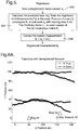
- Figures 6A and 6B illustrate the results of a simulation of two sensors configured to execute the method described above tracking one target.
- Each sensor provides the range and bearing of the target from its position.
- the target motion follows a random walk model and the tracker is based on an Unscented Kalman Filter.
- One of the sensors is not correctly registered and its position is reported to be 10 m west and 10 m south of its real position.
- the target is tracked for 200 m and the experiment is repeated 2 times with different initial positions.
- the training set for the registration algorithm is composed of 20 randomly distributed training points. In a real world application, those training points can be derived from the state information sent by the target at regular intervals.
- the accuracy of the tracking is compared using the Root Mean Squared Error of the position estimate and the true position of the target.
- Figure 6A is a graph showing example 2D coordinates of each target trajectory as measured by the sensor without running the registration process.
- Figure 6B is a similar graph showing the 2D trajectory with both sensors running the registration process described above (with 20 training points).
- the results are summarised in the following table: Situation Tracking error (RMSE) With registered sensors 0.4 m With unregistered sensors 8.3 m After correction with GP 0.8 m
- RMSE Situation Tracking error
Description
- The present invention relates to estimating a state of at least one target.
- Sensors are widely used for monitoring and surveillance applications and often track moving targets for various purposes, e.g. military or safety applications.
US4860216 discloses a multi-sensor system using multi-sensor data fusion for estimating target position measurements. - A known sensing technique that involves multiple sensors is a distributed sensor fusion network. The sensors in the network operate a Decentralised Data Fusion (DDF) algorithm (DDF is described in J. Manyika and H.F. Durrant-Whyte, Data Fusion and Sensor Management: A Decentralised Information-Theoretic Approach, Ellis Horwood, 1994), where data based on measurements taken by each sensor in the network are transmitted to the other sensors. Each sensor then performs a fusing operation on the data it has received from the other sensors as well as data based on its own measurements in order to predict the states (typically locations and velocities) of the targets.
- A problem associated with distributed sensor fusion networks is inadequate sensor registration. In multiple sensor surveillance systems/networks each sensor makes measurements of target positions in the survey volume and the measurements are integrated over time and combined using statistical data fusion algorithms to generate target tracks (a track typically comprises a position and velocity estimate and its calculated error). Sensor measurement errors are composed of two components: a random component ("noise") and a systematic component ("bias"). Sensor measurement errors can be constant or time-varying ("drift"). When multiple sensors are fused, uncorrected biases in their measurements can cause serious degradation of track estimates, which is known as the sensor registration problem. Sensor registration can be considered to be the process of estimating and removing a sensor's systematic errors, or "registration errors".
- An example of registration errors resulting from sensor pointing biases is illustrated in
Figure 1 . Twosensors target 104. Due to the pointing biases (e.g. the processors of the sensors have an inaccurate record of the sensors bearing measurement origins). Thefirst sensor 102A outputs a measurement of the target being atlocation 106A, whilst thesecond sensor 102B outputs a measurement of the target atlocation 106B. Other examples of registration errors include clock errors, tilt errors, and location errors (see M.P. Dana, "Registration: A pre-requisite for multiple sensor tracking". In Y. Bar-Shalom (Ed.), Multitarget-Multisensor Tracking: Advanced Applications. Artech House, 1990, Ch. 5, for example). - The effect of another example of registration errors is illustrated schematically in
Figure 2 , where four targets tracked from three different sensors produce a total of 10 different tracks. This proliferation of sensor tracks is a consequence of uncorrected registration errors adversely influencing the output of a multi-sensor multi-target tracking and data fusion system. - Common solutions to the sensor registration problem assume that registration errors can be described by a simple model (e.g. fixed offsets) and the parameters of that model are estimated as part of the data fusion process. In practice, registration errors exhibit spatial variations (due to environmental or other conditions) and it is unreasonable to assume all sources of registration error are known. New sources of errors may also arise as sensor technology develops. Furthermore, registration errors can change over time, due to sensor wearing, changes in environmental conditions, etc. It is usually very difficult to accurately model such errors as they are caused by natural phenomenon and can vary very slowly.
- Embodiments of the present invention are intended to address at least some of the problems outlined above.
- According to one aspect of the present invention there is provided a method of estimating a target measurement relating to at least one target position, the method including:
- obtaining at least one target measurement from a first sensor, and applying a Gaussian Process (GP) technique to a said target measurement to obtain an estimated updated target measurement by calculating a predicted bias for the measurement from a regression model represented by the GP and using the predicted bias to produce the updated target measurement.
- The first sensor may be part of a Distributed Data Fusion (DDF) network including at least one further sensor. The method may further include fusing the updated target measurement with at least one further target measurement obtained from the least one further sensor in the distributed sensor fusion network to generate a fused measurement or measurements relating to the at least one target. The step of applying the Gaussian Process technique can include performing a learning process based on the at least one target measurement and the fused measurement or measurements to generate a training set for use with the regression model. The learning process may involve calculating a covariance matrix and a Cholesky factor of the covariance matrix, where the Cholesky factor is used with the regression model for computational efficiency.
- The training set may initially include a measurement value known or assumed to represent an error-free measurement taken by the first sensor. The GP regression model may be a non-linear, non-parametric regression model.
- According to another aspect of the present invention there is provided a sensor configured to estimate a target measurement relating to at least one target position, the sensor including:
- a device configured to obtain at least one target measurement, and
- a processor configured to apply a Gaussian Process (GP) technique to a said target measurement to obtain an estimated updated measurement by calculating a predicted bias (Δzk *) for the measurement (zk ) from a regression model represented by the GP and using the predicted bias to produce the estimated updated target measurement (z̃k ).
- The processor may be integral with the sensor, or may be remote from it. According to another aspect of the present invention there is provided a computer program product comprising computer readable medium, having thereon computer program code means, when the program code is loaded, to make the computer execute a method of estimating a target measurement relating to at least one target position including:
- obtaining at least one target measurement from a first sensor, and
- applying a Gaussian Process (GP) technique to a said target measurement to estimate an updated target measurement by calculating a predicted bias (Δzk *) for the measurement (zk ) from a regression model represented by the GP and using the predicted bias to produce the estimated updated target measurement (z̃k ).
- According to a further aspect of the present invention there is provided a method of estimating a state of at least one target tracked by a plurality of sensors within a distributed sensor fusion network, wherein at least one of the sensors within the network has been registered using a technique involving a Gaussian Process.
- The invention may be performed in various ways, and, by way of example only, embodiments thereof will now be described, reference being made to the accompanying drawings in which:
-
Figure 1 is a schematic diagram of sensors tracking a target; -
Figure 2 illustrates schematically errors arising from pointing bias of sensors; -
Figure 3 illustrates schematically a data flow in an embodiment of the system including a sensor; -
Figure 4 illustrates schematically steps involved in a data selection and learning process relating to measurements taken by the sensor; -
Figure 5 illustrates schematically steps involved in a regression process for the sensor measurements; -
Figure 6A is a graphical representation of an example comparison between measured and true states of a target prior to registration of a sensor, and -
Figure 6B is a graphical representation of an example comparison between measured and true states of a target following registration of the sensor. - Referring to
Figure 3 , alocal sensor 302 obtains a measurement zk, where k is an index which refers to a discrete set of measurement times. The measurement will typically represent the location and velocity of the target, but other features, e.g. bearing, could be used. The measurement is passed to a registration process 304 (described below) that produces a corrected measurement value that compensates for any bias that is calculated to be present in the sensor, i.e. the corrected measurement value (z̃k ) is a revised record of the position of the sensor within the sensor network. In the present example, the correction is applied "virtually" in software, but it is also possible to apply the correction in hardware, i.e. physically reconfigure the sensor. It will be understood that the registration process may be executed by a processor integral with thesensor 302, or by a remote processor that receives data relating to the measurement taken by the sensor. - In the present embodiment the sensor is part of a DDF network of sensors and the updated measurement, which is intended to correct the bias in the original measurement taken by the sensor, is used in a fusion process along with measurements taken from the other sensors (all or some of which may also be executing a registration process 304), although it will be understood that calculating the updated/improved measurement can be of value for improving the accuracy of a measurement taken from a single sensor.
- The original measurement zk and the corrected measurement z̃k are passed to a
data fusion process 306. Theprocess 306 may comprise a conventional data fusion algorithm such as the Kalman filter or extended Kalman filter. At least one further measurement (zk n in the example) from at least one other sensor n in thenetwork 308 is also passed to thedata fusion process 306. Theprocess 306 produces a state estimate of mean x̂k and error covariance Pk that will normally have improved accuracy because errors resulting from incorrect sensor registration have been eliminated or mitigated. The Δzk value (that represents a calculated bias for the measurement zk taken by the sensor) resulting from thedata fusion process 306 is passed to a training data selection andlearning process 310. -
Figure 4 illustrates schematically steps involved in a learning procedure of the data selection andlearning process 310 shown inFigure 3 . In the embodiment described herein a Gaussian Process framework is used as a non-linear, non-parametric regression model. A training set of registration errors is used, which is built from the differences between unregistered and registered measurements, or their estimates. In the multiple sensor tracking system, estimates of registration errors can be derived from the state estimates of the target observed by the subset of registered sensors. If the target can provide its own (true) state, even sporadically, it can be used to derive the registration error of a sensor and added to the training set. The main advantages of Gaussian Processes over other non-parametric estimation techniques (e.g. Neural Networks) are: - More rigorous foundations and Bayesian approach
- Artificial Neural Networks cannot inherently give an indication of the error of their prediction and a constant error model is often used. In a sensor fusion setting (e.g. Kalman filter), this represents a loss of valuable information. It can even introduce large errors when the value is predicted far from any training data.
- Gaussian Processes provide the uncertainty of the predicted value (as the covariance of a Gaussian variable). For example, if no training data exists in the neighbourhood of the point of prediction, the error of the predicted value will be very large.
- Less sensitive to over fitting and over smoothing (Occam's razor). By comparing and optimizing over the marginal likelihood of the data, a complex model will not degrade the quality of the regression. The GP inference will adapt the complex model to the observed data and the desired uncertainty level.
- Adding new training data to the Gaussian process is relatively easy and efficient implementations of the procedure exist (see Osborne, M. A. and Roberts, S.J. (2007) Gaussian Processes for Prediction. Technical Report PARG-07-01, University of Oxford for an implementation)
- At
step 402, the state estimate of the target x̂k and its error covariance Pk (which is an indication of the likely error of the state estimate) are received from thedata fusion process 306, as well as the biased measurement zk from thelocal sensor 302. A training data selection algorithm atstep 402 decides whether the new biased measurement should be added to the training set. An example of a suitable decision algorithm, based on the comparison of the estimate covariance with and without the new training point, is described in the abovementioned Osborne and Roberts article under the name "Active Data Selection". Another possible selection algorithm is to use the true state of the target, when it is provided intermittently by the target. - At
step 404, an estimate of the unbiased measurement is calculated by using the observation matrix used by thedata fusion process 306. The bias Δz k is then calculated by taking the difference between the actual measurement zk and the estimation of the unbiased measurement. - The calculated bias Δzk and the original measurement zk are added to the training set at
step 406. The training set is formed of a set of the original measurements Y and a set of the biases ΔY (where M in the equations shown at 406 in the Figure represents the number of data points, i.e. the number of biased measurement and bias estimate data pairs, in the training set). - This regression model uses a Gaussian Process of covariance function k(x,y) with hyperparameters w to fit the training data. Typically, the covariance function is a squared exponential function, whose hyperparameters are the characteristic length-scales, one for each dimension of the measurement vector (see Gaussian Processes for Machine Learning Carl Edward Rasmussen and Christopher K. I. Williams The MIT Press, 2006. ISBN 0-262-18253-X,
Chapter 4 for further details). The hyperparameters of the covariance function are recalculated at 408 to fit the Gaussian Process model of the new training set. The fitting process maximizes the marginal likelihood of the data set based on the Gaussian Process of covariance k(x,y). The Gaussian assumptions allow the use of efficient optimization methods (as described in Section 5.4.1 of the abovementioned Rasmussen and Williams reference). - The covariance matrix is then calculated at
step 410 by simply applying the covariance function at the training points, with the optimized hyperparameters. Since theregression process 304 uses the inverse of the covariance matrix it is more computationally efficient to calculate the Cholesky decomposition of the covariance matrix once for all and then reuse the Choleksy factor LYY (lower factor in this example) to perform the regression. - Turning to
Figure 5 , a regression procedure that uses values calculated during the learning procedure ofFigure 4 is outlined. The learning procedure is normally executed only if thedata selection algorithm 402 is performed. The regression procedure ofFigure 5 is always executed following the reception of a new measurement from the sensor, resulting in an "online" registration procedure. - At
step 502 the biased measurement zk from thelocal sensor 302 is received. Atstep 504 the predicted bias Δzk * for the sensor measurement zk is calculated from a regression model represented by a Gaussian Process:
- The Gaussian Process is modelled by the covariance matrix KYY but the regression actually uses its Cholesky factor LYY calculated at 410 for computational efficiency. (The equations of the regression model, including the use of the Cholesky factor, are discussed in Section 2.2 of the abovementioned Rasmussen and Williams reference).
- At
step 506 the biased measurement zk is corrected by adding the bias Δzk * calculated atstep 504. This corrected value z̃k is then output by theregistration process 304. -
Figures 6A and6B illustrate the results of a simulation of two sensors configured to execute the method described above tracking one target. Each sensor provides the range and bearing of the target from its position. The target motion follows a random walk model and the tracker is based on an Unscented Kalman Filter. One of the sensors is not correctly registered and its position is reported to be 10 m west and 10 m south of its real position. The target is tracked for 200 m and the experiment is repeated 2 times with different initial positions. The training set for the registration algorithm is composed of 20 randomly distributed training points. In a real world application, those training points can be derived from the state information sent by the target at regular intervals. The accuracy of the tracking is compared using the Root Mean Squared Error of the position estimate and the true position of the target. -
Figure 6A is a graph showing example 2D coordinates of each target trajectory as measured by the sensor without running the registration process.Figure 6B is a similar graph showing the 2D trajectory with both sensors running the registration process described above (with 20 training points). The results are summarised in the following table:Situation Tracking error (RMSE) With registered sensors 0.4 m With unregistered sensors 8.3 m After correction with GP 0.8 m
Claims (9)
- A method of estimating a target measurement relating to at least one target position, the method including:obtaining at least one target measurement (zk ) from a first sensor, andapplying a Gaussian Process (GP) technique to a said target measurement to obtain an estimated updated target measurement (z̃k ) by calculating a predicted bias (Δzk * ) for the measurement (zk ) from a regression model represented by the GP and using the predicted bias to produce the estimated updated target measurement (z̃k ).
- A method according to claim 1, wherein the first sensor is part of a distributed sensor fusion network including at least one further sensor.
- A method according to claim 2, further including fusing the estimated updated target measurement with at least one further target measurement (zk ") obtained from at least one further sensor in the distributed sensor fusion network to generate a fused measurement or measurements (x̂k ,Pk ) relating to the at least one target.
- A method according to claim 3, wherein the applying of the Gaussian Process (GP) technique includes performing a learning process based on the at least one target measurement (zk ) and the fused measurement or measurements (x̂k,Pk ) to generate a training set for use with the regression model.
- A method according to claim 4, wherein the learning process involves calculating a covariance matrix (KYY ) and a Cholesky factor (LYY ) of the covariance matrix, where the Choleksy factor is used with the regression model for computational efficiency.
- A method according to claim 4 or 5, wherein the training set initially includes a measurement value known or assumed to represent an error-free measurement taken by the first sensor.
- A method according to any one of the preceding claims, wherein the GP regression model is a non-linear, non-parametric regression model.
- A sensor configured to estimate a target measurement relating to at least one target position, the sensor including:a device configured to obtain at least one target measurement, andcharacterised by includinga processor configured to apply a Gaussian Process (GP) technique to a said target measurement to obtain an estimated updated measurement by calculating a predicted bias (Δzk *) for the measurement (zk ) from a regression model represented by the GP and using the predicted bias to produce the estimated updated target measurement (z̃k ).
- A computer program product comprising computer readable medium, having thereon computer program code means, when the program code is loaded, to make the computer execute a method of estimating a target measurement relating to at least one target position including:obtaining at least one target measurement from a first sensor, andapplying a Gaussian Process (GP) technique to a said target measurement to estimate an updated target measurement by calculating a predicted bias (Δzk *) for the measurement (zk ) from a regression model represented by the GP and using the predicted bias to produce the estimated updated target measurement (z̃k ).
Priority Applications (1)
| Application Number | Priority Date | Filing Date | Title |
|---|---|---|---|
| EP09785562.1A EP2332017B1 (en) | 2008-09-03 | 2009-09-02 | Estimating a state of at least one target |
Applications Claiming Priority (4)
| Application Number | Priority Date | Filing Date | Title |
|---|---|---|---|
| EP08275048A EP2161634A1 (en) | 2008-09-03 | 2008-09-03 | Estimating a state of at least one target |
| GB0816040A GB0816040D0 (en) | 2008-09-03 | 2008-09-03 | Estimating a state of at least one target |
| EP09785562.1A EP2332017B1 (en) | 2008-09-03 | 2009-09-02 | Estimating a state of at least one target |
| PCT/GB2009/051103 WO2010026417A1 (en) | 2008-09-03 | 2009-09-02 | Estimating a state of at least one target |
Publications (2)
| Publication Number | Publication Date |
|---|---|
| EP2332017A1 EP2332017A1 (en) | 2011-06-15 |
| EP2332017B1 true EP2332017B1 (en) | 2016-03-30 |
Family
ID=41397524
Family Applications (1)
| Application Number | Title | Priority Date | Filing Date |
|---|---|---|---|
| EP09785562.1A Active EP2332017B1 (en) | 2008-09-03 | 2009-09-02 | Estimating a state of at least one target |
Country Status (7)
| Country | Link |
|---|---|
| US (1) | US20120030154A1 (en) |
| EP (1) | EP2332017B1 (en) |
| AU (1) | AU2009289008B2 (en) |
| BR (1) | BRPI0915941A2 (en) |
| CA (1) | CA2735787A1 (en) |
| IL (1) | IL211520A0 (en) |
| WO (1) | WO2010026417A1 (en) |
Families Citing this family (17)
| Publication number | Priority date | Publication date | Assignee | Title |
|---|---|---|---|---|
| EP2184681A1 (en) * | 2008-10-31 | 2010-05-12 | HSBC Holdings plc | Capacity control |
| CA2774158A1 (en) * | 2009-09-15 | 2011-03-24 | The University Of Sydney | A method and system for multiple dataset gaussian process modeling |
| US9070285B1 (en) * | 2011-07-25 | 2015-06-30 | UtopiaCompression Corporation | Passive camera based cloud detection and avoidance for aircraft systems |
| US9363154B2 (en) * | 2012-09-26 | 2016-06-07 | International Business Machines Corporaion | Prediction-based provisioning planning for cloud environments |
| WO2015140517A1 (en) * | 2014-03-17 | 2015-09-24 | Bae Systems Plc | Producing data describing target measurements |
| EP2921878A1 (en) * | 2014-03-17 | 2015-09-23 | BAE Systems PLC | Producing data describing target states |
| US10031221B2 (en) * | 2016-03-03 | 2018-07-24 | Raytheon Company | System and method for estimating number and range of a plurality of moving targets |
| US10942029B2 (en) | 2016-11-04 | 2021-03-09 | The Boeing Company | Tracking a target using multiple tracking systems |
| US10606266B2 (en) * | 2016-11-04 | 2020-03-31 | The Boeing Company | Tracking a target moving between states in an environment |
| JP6759130B2 (en) * | 2017-03-03 | 2020-09-23 | 株式会社東芝 | Sensor network system, data fusion system, sensor bias estimation device, sensor bias estimation method and sensor bias estimation program |
| WO2018168182A1 (en) * | 2017-03-17 | 2018-09-20 | 日本電気株式会社 | Mobiile body detection device, mobile body detection method, and mobile body detection program |
| CN107944115A (en) * | 2017-11-17 | 2018-04-20 | 中国科学院、水利部成都山地灾害与环境研究所 | Uncertain Synthetic Measurement method in ecological parameter terrestrial wireless networking observation |
| US10977110B2 (en) * | 2017-12-27 | 2021-04-13 | Palo Alto Research Center Incorporated | System and method for facilitating prediction data for device based on synthetic data with uncertainties |
| US11521063B1 (en) * | 2019-12-17 | 2022-12-06 | Bae Systems Information And Electronic Systems Integration Inc. | System and method for terminal acquisition with a neural network |
| CN111843626B (en) * | 2020-07-16 | 2021-11-30 | 上海交通大学 | Gauss model-based hysteresis modeling method, system and medium for air-driven actuator |
| US11900457B2 (en) * | 2020-08-24 | 2024-02-13 | Leonid Chuzhoy | Methods for prediction and rating aggregation |
| CN113687143B (en) * | 2021-08-12 | 2024-04-05 | 国网上海市电力公司 | Fitting method of electromagnetic wave signal amplitude attenuation and propagation distance relation curve |
Family Cites Families (5)
| Publication number | Priority date | Publication date | Assignee | Title |
|---|---|---|---|---|
| US4860216A (en) * | 1986-11-13 | 1989-08-22 | The United States Of America As Represented By The Secretary Of The Air Force | Communication adaptive multi-sensor system |
| SE510844C2 (en) * | 1997-11-03 | 1999-06-28 | Celsiustech Syst Ab | Automatic compensation of systematic errors in target tracking with multiple sensors |
| US6225942B1 (en) * | 1999-07-30 | 2001-05-01 | Litton Systems, Inc. | Registration method for multiple sensor radar |
| US6801662B1 (en) * | 2000-10-10 | 2004-10-05 | Hrl Laboratories, Llc | Sensor fusion architecture for vision-based occupant detection |
| US7583815B2 (en) * | 2005-04-05 | 2009-09-01 | Objectvideo Inc. | Wide-area site-based video surveillance system |
-
2009
- 2009-09-02 BR BRPI0915941A patent/BRPI0915941A2/en not_active IP Right Cessation
- 2009-09-02 WO PCT/GB2009/051103 patent/WO2010026417A1/en active Application Filing
- 2009-09-02 CA CA2735787A patent/CA2735787A1/en not_active Abandoned
- 2009-09-02 US US13/062,096 patent/US20120030154A1/en not_active Abandoned
- 2009-09-02 EP EP09785562.1A patent/EP2332017B1/en active Active
- 2009-09-02 AU AU2009289008A patent/AU2009289008B2/en active Active
-
2011
- 2011-03-02 IL IL211520A patent/IL211520A0/en unknown
Also Published As
| Publication number | Publication date |
|---|---|
| CA2735787A1 (en) | 2010-03-11 |
| WO2010026417A1 (en) | 2010-03-11 |
| AU2009289008B2 (en) | 2014-02-13 |
| BRPI0915941A2 (en) | 2015-11-03 |
| US20120030154A1 (en) | 2012-02-02 |
| AU2009289008A1 (en) | 2010-03-11 |
| IL211520A0 (en) | 2011-05-31 |
| EP2332017A1 (en) | 2011-06-15 |
Similar Documents
| Publication | Publication Date | Title |
|---|---|---|
| EP2332017B1 (en) | Estimating a state of at least one target | |
| CN111178385B (en) | Target tracking method for robust online multi-sensor fusion | |
| CN109597864B (en) | Method and system for real-time positioning and map construction of ellipsoid boundary Kalman filtering | |
| CN108535720B (en) | Adaptive process noise description for improved Kalman filtering target tracking | |
| Kalandros et al. | Tutorial on multisensor management and fusion algorithms for target tracking | |
| US7941292B2 (en) | Associating observations in a multi-sensor system using an adaptive gate value | |
| CN104462015B (en) | Process the fractional order linear discrete system state updating method of non-gaussian L é vy noises | |
| CN110889862B (en) | Combined measurement method for multi-target tracking in network transmission attack environment | |
| Lan et al. | Joint target detection and tracking in multipath environment: A variational Bayesian approach | |
| Attari et al. | An SVSF-based generalized robust strategy for target tracking in clutter | |
| CN108226887B (en) | Water surface target rescue state estimation method under condition of transient observation loss | |
| Farrell et al. | Advanced vehicle state estimation: A tutorial and comparative study | |
| CN107247257A (en) | Tracking before a kind of distributed multi-sensor detection approximate based on likelihood function | |
| EP2161634A1 (en) | Estimating a state of at least one target | |
| Mohammadi et al. | Distributed posterior Cramér-Rao lower bound for nonlinear sequential Bayesian estimation | |
| CN104050686A (en) | Novel intensive space target tracking method | |
| CN108445517B (en) | A kind of positioning signal filtering method, device and equipment | |
| CN115328168A (en) | Mobile robot synchronous positioning and mapping method and system based on adaptive strong tracking | |
| Chen | An algorithm of mobile sensors data fusion tracking for wireless sensor networks | |
| CN110515069B (en) | Self-adaptive consistency information filtering method for distributed target tracking | |
| Kwok et al. | A modified particle filter for simultaneous localization and mapping | |
| CN109343013B (en) | Spatial registration method and system based on restarting mechanism | |
| Yang et al. | Variational Approximation for Adaptive Extended Target Tracking in Clutter with Random Matrix | |
| Huang et al. | Analytically-selected multi-hypothesis incremental MAP estimation | |
| Martinez et al. | Feature uncertainty estimation in sensor fusion applied to autonomous vehicle location |
Legal Events
| Date | Code | Title | Description |
|---|---|---|---|
| PUAI | Public reference made under article 153(3) epc to a published international application that has entered the european phase |
Free format text: ORIGINAL CODE: 0009012 |
|
| 17P | Request for examination filed |
Effective date: 20110331 |
|
| AK | Designated contracting states |
Kind code of ref document: A1 Designated state(s): AT BE BG CH CY CZ DE DK EE ES FI FR GB GR HR HU IE IS IT LI LT LU LV MC MK MT NL NO PL PT RO SE SI SK SM TR |
|
| AX | Request for extension of the european patent |
Extension state: AL BA RS |
|
| DAX | Request for extension of the european patent (deleted) | ||
| REG | Reference to a national code |
Ref country code: DE Ref legal event code: R079 Ref document number: 602009037330 Country of ref document: DE Free format text: PREVIOUS MAIN CLASS: G05B0013000000 Ipc: G01S0007000000 |
|
| GRAP | Despatch of communication of intention to grant a patent |
Free format text: ORIGINAL CODE: EPIDOSNIGR1 |
|
| RIC1 | Information provided on ipc code assigned before grant |
Ipc: G01S 13/72 20060101ALI20150923BHEP Ipc: G01S 7/00 20060101AFI20150923BHEP Ipc: G01S 13/86 20060101ALI20150923BHEP |
|
| INTG | Intention to grant announced |
Effective date: 20151020 |
|
| GRAS | Grant fee paid |
Free format text: ORIGINAL CODE: EPIDOSNIGR3 |
|
| GRAA | (expected) grant |
Free format text: ORIGINAL CODE: 0009210 |
|
| AK | Designated contracting states |
Kind code of ref document: B1 Designated state(s): AT BE BG CH CY CZ DE DK EE ES FI FR GB GR HR HU IE IS IT LI LT LU LV MC MK MT NL NO PL PT RO SE SI SK SM TR |
|
| REG | Reference to a national code |
Ref country code: GB Ref legal event code: FG4D |
|
| REG | Reference to a national code |
Ref country code: CH Ref legal event code: EP |
|
| REG | Reference to a national code |
Ref country code: AT Ref legal event code: REF Ref document number: 785958 Country of ref document: AT Kind code of ref document: T Effective date: 20160415 |
|
| REG | Reference to a national code |
Ref country code: IE Ref legal event code: FG4D |
|
| REG | Reference to a national code |
Ref country code: DE Ref legal event code: R096 Ref document number: 602009037330 Country of ref document: DE |
|
| REG | Reference to a national code |
Ref country code: NL Ref legal event code: FP |
|
| REG | Reference to a national code |
Ref country code: LT Ref legal event code: MG4D |
|
| PG25 | Lapsed in a contracting state [announced via postgrant information from national office to epo] |
Ref country code: HR Free format text: LAPSE BECAUSE OF FAILURE TO SUBMIT A TRANSLATION OF THE DESCRIPTION OR TO PAY THE FEE WITHIN THE PRESCRIBED TIME-LIMIT Effective date: 20160330 Ref country code: GR Free format text: LAPSE BECAUSE OF FAILURE TO SUBMIT A TRANSLATION OF THE DESCRIPTION OR TO PAY THE FEE WITHIN THE PRESCRIBED TIME-LIMIT Effective date: 20160701 Ref country code: FI Free format text: LAPSE BECAUSE OF FAILURE TO SUBMIT A TRANSLATION OF THE DESCRIPTION OR TO PAY THE FEE WITHIN THE PRESCRIBED TIME-LIMIT Effective date: 20160330 Ref country code: NO Free format text: LAPSE BECAUSE OF FAILURE TO SUBMIT A TRANSLATION OF THE DESCRIPTION OR TO PAY THE FEE WITHIN THE PRESCRIBED TIME-LIMIT Effective date: 20160630 |
|
| REG | Reference to a national code |
Ref country code: AT Ref legal event code: MK05 Ref document number: 785958 Country of ref document: AT Kind code of ref document: T Effective date: 20160330 |
|
| PG25 | Lapsed in a contracting state [announced via postgrant information from national office to epo] |
Ref country code: LV Free format text: LAPSE BECAUSE OF FAILURE TO SUBMIT A TRANSLATION OF THE DESCRIPTION OR TO PAY THE FEE WITHIN THE PRESCRIBED TIME-LIMIT Effective date: 20160330 Ref country code: SE Free format text: LAPSE BECAUSE OF FAILURE TO SUBMIT A TRANSLATION OF THE DESCRIPTION OR TO PAY THE FEE WITHIN THE PRESCRIBED TIME-LIMIT Effective date: 20160330 Ref country code: LT Free format text: LAPSE BECAUSE OF FAILURE TO SUBMIT A TRANSLATION OF THE DESCRIPTION OR TO PAY THE FEE WITHIN THE PRESCRIBED TIME-LIMIT Effective date: 20160330 |
|
| REG | Reference to a national code |
Ref country code: FR Ref legal event code: PLFP Year of fee payment: 8 |
|
| PG25 | Lapsed in a contracting state [announced via postgrant information from national office to epo] |
Ref country code: IS Free format text: LAPSE BECAUSE OF FAILURE TO SUBMIT A TRANSLATION OF THE DESCRIPTION OR TO PAY THE FEE WITHIN THE PRESCRIBED TIME-LIMIT Effective date: 20160730 Ref country code: PL Free format text: LAPSE BECAUSE OF FAILURE TO SUBMIT A TRANSLATION OF THE DESCRIPTION OR TO PAY THE FEE WITHIN THE PRESCRIBED TIME-LIMIT Effective date: 20160330 Ref country code: EE Free format text: LAPSE BECAUSE OF FAILURE TO SUBMIT A TRANSLATION OF THE DESCRIPTION OR TO PAY THE FEE WITHIN THE PRESCRIBED TIME-LIMIT Effective date: 20160330 |
|
| PG25 | Lapsed in a contracting state [announced via postgrant information from national office to epo] |
Ref country code: CZ Free format text: LAPSE BECAUSE OF FAILURE TO SUBMIT A TRANSLATION OF THE DESCRIPTION OR TO PAY THE FEE WITHIN THE PRESCRIBED TIME-LIMIT Effective date: 20160330 Ref country code: RO Free format text: LAPSE BECAUSE OF FAILURE TO SUBMIT A TRANSLATION OF THE DESCRIPTION OR TO PAY THE FEE WITHIN THE PRESCRIBED TIME-LIMIT Effective date: 20160330 Ref country code: ES Free format text: LAPSE BECAUSE OF FAILURE TO SUBMIT A TRANSLATION OF THE DESCRIPTION OR TO PAY THE FEE WITHIN THE PRESCRIBED TIME-LIMIT Effective date: 20160330 Ref country code: SK Free format text: LAPSE BECAUSE OF FAILURE TO SUBMIT A TRANSLATION OF THE DESCRIPTION OR TO PAY THE FEE WITHIN THE PRESCRIBED TIME-LIMIT Effective date: 20160330 Ref country code: PT Free format text: LAPSE BECAUSE OF FAILURE TO SUBMIT A TRANSLATION OF THE DESCRIPTION OR TO PAY THE FEE WITHIN THE PRESCRIBED TIME-LIMIT Effective date: 20160801 Ref country code: SM Free format text: LAPSE BECAUSE OF FAILURE TO SUBMIT A TRANSLATION OF THE DESCRIPTION OR TO PAY THE FEE WITHIN THE PRESCRIBED TIME-LIMIT Effective date: 20160330 Ref country code: AT Free format text: LAPSE BECAUSE OF FAILURE TO SUBMIT A TRANSLATION OF THE DESCRIPTION OR TO PAY THE FEE WITHIN THE PRESCRIBED TIME-LIMIT Effective date: 20160330 |
|
| PG25 | Lapsed in a contracting state [announced via postgrant information from national office to epo] |
Ref country code: IT Free format text: LAPSE BECAUSE OF FAILURE TO SUBMIT A TRANSLATION OF THE DESCRIPTION OR TO PAY THE FEE WITHIN THE PRESCRIBED TIME-LIMIT Effective date: 20160330 Ref country code: BE Free format text: LAPSE BECAUSE OF FAILURE TO SUBMIT A TRANSLATION OF THE DESCRIPTION OR TO PAY THE FEE WITHIN THE PRESCRIBED TIME-LIMIT Effective date: 20160330 |
|
| REG | Reference to a national code |
Ref country code: DE Ref legal event code: R097 Ref document number: 602009037330 Country of ref document: DE |
|
| PG25 | Lapsed in a contracting state [announced via postgrant information from national office to epo] |
Ref country code: DK Free format text: LAPSE BECAUSE OF FAILURE TO SUBMIT A TRANSLATION OF THE DESCRIPTION OR TO PAY THE FEE WITHIN THE PRESCRIBED TIME-LIMIT Effective date: 20160330 |
|
| PLBE | No opposition filed within time limit |
Free format text: ORIGINAL CODE: 0009261 |
|
| STAA | Information on the status of an ep patent application or granted ep patent |
Free format text: STATUS: NO OPPOSITION FILED WITHIN TIME LIMIT |
|
| 26N | No opposition filed |
Effective date: 20170103 |
|
| PG25 | Lapsed in a contracting state [announced via postgrant information from national office to epo] |
Ref country code: MC Free format text: LAPSE BECAUSE OF FAILURE TO SUBMIT A TRANSLATION OF THE DESCRIPTION OR TO PAY THE FEE WITHIN THE PRESCRIBED TIME-LIMIT Effective date: 20160330 |
|
| REG | Reference to a national code |
Ref country code: CH Ref legal event code: PL |
|
| PG25 | Lapsed in a contracting state [announced via postgrant information from national office to epo] |
Ref country code: SI Free format text: LAPSE BECAUSE OF FAILURE TO SUBMIT A TRANSLATION OF THE DESCRIPTION OR TO PAY THE FEE WITHIN THE PRESCRIBED TIME-LIMIT Effective date: 20160330 |
|
| REG | Reference to a national code |
Ref country code: IE Ref legal event code: MM4A |
|
| PG25 | Lapsed in a contracting state [announced via postgrant information from national office to epo] |
Ref country code: LI Free format text: LAPSE BECAUSE OF NON-PAYMENT OF DUE FEES Effective date: 20160930 Ref country code: IE Free format text: LAPSE BECAUSE OF NON-PAYMENT OF DUE FEES Effective date: 20160902 Ref country code: CH Free format text: LAPSE BECAUSE OF NON-PAYMENT OF DUE FEES Effective date: 20160930 |
|
| PG25 | Lapsed in a contracting state [announced via postgrant information from national office to epo] |
Ref country code: LU Free format text: LAPSE BECAUSE OF NON-PAYMENT OF DUE FEES Effective date: 20160902 |
|
| REG | Reference to a national code |
Ref country code: FR Ref legal event code: PLFP Year of fee payment: 9 |
|
| PG25 | Lapsed in a contracting state [announced via postgrant information from national office to epo] |
Ref country code: CY Free format text: LAPSE BECAUSE OF FAILURE TO SUBMIT A TRANSLATION OF THE DESCRIPTION OR TO PAY THE FEE WITHIN THE PRESCRIBED TIME-LIMIT Effective date: 20160330 Ref country code: HU Free format text: LAPSE BECAUSE OF FAILURE TO SUBMIT A TRANSLATION OF THE DESCRIPTION OR TO PAY THE FEE WITHIN THE PRESCRIBED TIME-LIMIT; INVALID AB INITIO Effective date: 20090902 |
|
| PG25 | Lapsed in a contracting state [announced via postgrant information from national office to epo] |
Ref country code: TR Free format text: LAPSE BECAUSE OF FAILURE TO SUBMIT A TRANSLATION OF THE DESCRIPTION OR TO PAY THE FEE WITHIN THE PRESCRIBED TIME-LIMIT Effective date: 20160330 Ref country code: MT Free format text: LAPSE BECAUSE OF NON-PAYMENT OF DUE FEES Effective date: 20160930 Ref country code: MK Free format text: LAPSE BECAUSE OF FAILURE TO SUBMIT A TRANSLATION OF THE DESCRIPTION OR TO PAY THE FEE WITHIN THE PRESCRIBED TIME-LIMIT Effective date: 20160330 |
|
| PG25 | Lapsed in a contracting state [announced via postgrant information from national office to epo] |
Ref country code: BG Free format text: LAPSE BECAUSE OF FAILURE TO SUBMIT A TRANSLATION OF THE DESCRIPTION OR TO PAY THE FEE WITHIN THE PRESCRIBED TIME-LIMIT Effective date: 20160330 |
|
| REG | Reference to a national code |
Ref country code: FR Ref legal event code: PLFP Year of fee payment: 10 |
|
| PGFP | Annual fee paid to national office [announced via postgrant information from national office to epo] |
Ref country code: NL Payment date: 20230822 Year of fee payment: 15 |
|
| PGFP | Annual fee paid to national office [announced via postgrant information from national office to epo] |
Ref country code: GB Payment date: 20230823 Year of fee payment: 15 |
|
| PGFP | Annual fee paid to national office [announced via postgrant information from national office to epo] |
Ref country code: FR Payment date: 20230822 Year of fee payment: 15 Ref country code: DE Payment date: 20230822 Year of fee payment: 15 |