EP2331036B1 - Device for treating night time breathing problems - Google Patents
Device for treating night time breathing problems Download PDFInfo
- Publication number
- EP2331036B1 EP2331036B1 EP09775649.8A EP09775649A EP2331036B1 EP 2331036 B1 EP2331036 B1 EP 2331036B1 EP 09775649 A EP09775649 A EP 09775649A EP 2331036 B1 EP2331036 B1 EP 2331036B1
- Authority
- EP
- European Patent Office
- Prior art keywords
- coupling element
- jaw
- relation
- contact portion
- base portion
- Prior art date
- Legal status (The legal status is an assumption and is not a legal conclusion. Google has not performed a legal analysis and makes no representation as to the accuracy of the status listed.)
- Active
Links
Images

Classifications
-
- A—HUMAN NECESSITIES
- A61—MEDICAL OR VETERINARY SCIENCE; HYGIENE
- A61F—FILTERS IMPLANTABLE INTO BLOOD VESSELS; PROSTHESES; DEVICES PROVIDING PATENCY TO, OR PREVENTING COLLAPSING OF, TUBULAR STRUCTURES OF THE BODY, e.g. STENTS; ORTHOPAEDIC, NURSING OR CONTRACEPTIVE DEVICES; FOMENTATION; TREATMENT OR PROTECTION OF EYES OR EARS; BANDAGES, DRESSINGS OR ABSORBENT PADS; FIRST-AID KITS
- A61F5/00—Orthopaedic methods or devices for non-surgical treatment of bones or joints; Nursing devices ; Anti-rape devices
- A61F5/56—Devices for preventing snoring
- A61F5/566—Intra-oral devices
Definitions
- the present invention relates to a device for treating breathing problems, comprising
- Night-time breathing problems which can for instance result in snoring, sleep apnoea syndrome or other sleep disorders are a generally known problem.
- the rear part of the tongue may tend to slide backwards, whereby the pharyngeal airway is wholly or partially closed off.
- the neck muscles are hereby forced into a tensioned position, whereby the tongue moves forward and the airway is left clear.
- Said devices placeable in the mouth are generally known and can be found in a number of different embodiments, including embodiments as described in the preamble which have been known since the 1990s.
- the known embodiments have the drawback that they allow too much freedom of movement during opening/closing of the mouth.
- the invention has for its object to provide a device according to the preamble of claim 1, which is user-friendly and agreeable to wear, and allows a precise adjustment with a limited freedom of movement of the lower jaw in relation to the upper jaw.
- the invention is distinguished for this purpose by the features of the characterizing portion of claim 1.
- the upper coupling element is provided with a stop for co-action with a contact surface of the lower coupling element, such that when lower and upper jaw are moved towards each other a further closing of the mouth is prevented when the contact surface comes up against the stop.
- the left and right, upper and lower coupling elements are further connected to respectively the upper and lower part such that they are situated in the oral vestibule ( vestibulum oris ) in the position of the device placed in the mouth, i.e. the coupling elements are situated between the teeth and respectively the left and right cheek.
- At least one coupling element of the upper and the lower coupling elements is provided with vertical adjusting means for adjusting the vertical position of the stop/the contact surface in relation to the lower jaw in order to obtain an adjustable minimum distance between lower jaw and upper jaw.
- the at least one coupling element comprises a contact portion and a base portion connected respectively to the upper or lower part, wherein vertical adjusting means are provided between the contact portion and the base portion for the purpose of adjusting the vertical position of the contact portion in relation to the base portion.
- the adjusting means comprise a substantially vertical adjusting screw with double screw thread for the up/downward adjustment of the contact portion in relation to the base portion, which adjusting screw co-acts at one outer end with a first threaded bore in the contact portion and co-acts at its other outer end with a second threaded bore in the base portion, wherein a rotation of the adjusting screw changes the distance between the first and second threaded bore.
- the adjusting screw is provided substantially in the centre with an encircling flange with radially directed openings into which a rod fits for the purpose of rotating the adjusting screw by rotating the rod. In this way the vertical distance can be adjusted in convenient manner. Telescopically acting tubes between base portion and contact portion can further be provided on either side of the vertical adjusting screw so as to thus improve the stability of the device.
- At least one coupling element of the upper and the lower coupling element comprises a fixed part which is connected to respectively the lower part or upper part, and a part which is displaceable relative to this fixed part substantially parallel to respectively the lower part or upper part.
- "Parallel to respectively the lower part or upper part” should be understood to mean substantially parallel to the plane of respectively the lower teeth or the upper teeth when the device is placed in the mouth. In this way the moving forward of the lower jaw in relation to the upper jaw can likewise be adjusted.
- the displaceable part comprises the contact portion such that both a horizontal and vertical displacement are possible.
- Horizontal should here be understood to mean substantially parallel to the plane of respectively the lower teeth or the upper teeth when the device is placed in the mouth, depending on whether the displaceable part is situated in respectively the upper or lower coupling element.
- Vertical should then be understood to mean substantially perpendicular to respectively the plane of the lower jaw or of the upper jaw.
- Each upper coupling element is provided with a substantially vertical portion with a concave or convex surface directed toward the front teeth, and each lower coupling element is provided with a substantially complementarily shaped surface, this such that the upper coupling element can engage in the lower coupling element and that rearward movement of the lower jaw is avoided.
- the vertical movement of upper coupling element in relation to lower coupling element is further guided and limited, while a lateral movement of upper jaw in relation to lower jaw is a possibility, as will be further elucidated.
- the upper and lower coupling elements are designed such that a limited lateral or sideways movement of the lower part arranged on the lower jaw in relation to the upper part arranged on the upper jaw, i.e. a movement in the plane of the teeth and substantially perpendicularly of the back teeth, is possible.
- a limited lateral freedom of movement further increases the wearing comfort without having serious consequences for the accuracy of adjustment.
- the lower coupling element lies in lateral direction at a distance from the upper part in the position of the device placed in the mouth.
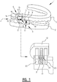
- FIG. 1 and figures 3(A) &(B) and figure 4 illustrate a preferred embodiment of an oral apparatus 1 for treating breathing problems.
- This apparatus 1 comprises a lower part mountable on the lower jaw in the form of a shaped part 2 and an upper part mountable on the upper jaw in the form of a shaped part 3.
- the skilled person will understand that the lower and upper part may also be embodied differently and the term part is understood to mean for instance a brace with a palate plate as well as a flexible bite-block.
- the only requirement is that the lower and upper parts are situated at least in the vicinity of the back teeth such that coupling elements can there be mounted on the lower/upper part 2, 3.
- the apparatus further comprises left and right coupling means 4 (for the sake of simplicity only the left coupling means are shown in figure 1 ) for coupling lower part 2 to upper part 3 close to the back teeth.
- Each of the left and right coupling means 4 comprises an upper coupling element 6 connected to upper part 3 and a lower coupling element 5 connected to lower part 2.
- these coupling means 4 are situated on the vestibular side of the tooth arch, i.e. between the cheek and the tooth arches.
- the left and right coupling means 4 are adapted to move the lower jaw forward in relation to the upper jaw, while the up/downward movement of the lower jaw in relation to upper jaw is also controlled.
- lower coupling element 5 consists of three parts: a fixed part 9, a central part 8, and an upper part 7.
- Fixed part 9 is attached to lower part 2 and connected via horizontal adjusting means 11 to central part 8.
- Central part 8 is connected via vertical adjusting means 10 to upper part 7.
- Part 7 functions here as a contact portion with a contact surface 12 for the purpose of making contact with a stop 13 of upper coupling element 6 when the mouth is closed.
- Parts 8 and 9 can be seen as a base portion. Contact portion 7 can be moved upward/downward in relation to base portion 8, 9 using adjusting means 10.
- Central part 8 is further horizontally displaceable in relation to fixed part 9 via adjusting means 11, wherein horizontally is understood to mean substantially parallel to lower part 2.
- Parts 7 and 8 thus form a block which is horizontally displaceable in relation to fixed part 9.
- Parts 7, 8 and 9 with associated adjusting means thus allow adjustment of both the vertical and the horizontal position of contact surface 12 in order to obtain an adjustable minimum vertical and horizontal distance between lower jaw and upper jaw.
- Upper coupling element 6 is provided with a substantially vertical portion 14 with a concave surface 15 directed toward the front teeth, and contact portion 7 of lower coupling element 5 is provided with a substantially complementarily shaped surface 16. In this way the upper coupling element can engage in the lower coupling element and the vertical movement of lower jaw in relation to upper jaw is further guided and limited.
- the vertical and horizontal adjusting means 10, 11 consist in each case of a central adjusting screw 17, 18 with double screw thread for respectively up/downward and front/backward adjustment of contact portion 7 relative to fixed part 9.
- a central adjusting screw 17, 18 Arranged on either side of each central adjusting screw 17, 18 are telescopically acting tubes 22, 23 and 24, 25 parallel thereto (see in particular figure 3(B) ).
- the central vertical adjusting screw 17 co-acts at one outer end with a first threaded bore in contact portion 7 and at its other outer end with a second threaded bore in central part 8, wherein a rotation of the adjusting screw changes the distance between the first and second threaded bore.
- the central horizontal adjusting screw 18 co-acts on one side with a threaded bore in central part 8 and on the other with a threaded bore in fixed part 9.
- Each adjusting screw 17, 18 is preferably provided substantially in the centre with an encircling flange 21 with radially directed openings 20 into which a rod fits for the purpose of rotating the adjusting screw by rotating the rod.
- Figure 3(A) shows upper coupling element 6 in detail.
- the dimensions of this element 6 can for instance be as follows:
- each upper coupling element 6 can move laterally or sideways in limited manner (see arrow 30 in figure 4 ) in relation to the lower coupling element in a position of the oral apparatus placed in the mouth.
- the width w2 of upper coupling element 6 is for this purpose smaller than the width w1 of lower coupling element 5, and the lower coupling element is placed further outward (here over a distance w1-w2, although the skilled person will appreciate that this distance may also be to some extent smaller or greater).
- lower coupling element 5 will be situated at a distance in lateral direction from the upper part when the device is placed in the mouth, and will thus allow a lateral movement of upper part in relation to lower part.
- lower coupling element 105 consists of two parts: a base portion 109 and a contact portion 107.
- Contact portion 107 has a contact surface 112, the height of which is adjustable using vertical adjusting means 110.
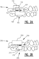
- Figure 2(B) shows an equivalent variant wherein base portion 209 and the vertically adjustable contact portion 207 are provided in upper coupling element 206 and stop 213 is situated on the bottom of contact portion 207, while contact surface 212 is provided on lower coupling element 205.
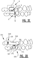
- FIG. 2(C) shows a reverse variant in which parts 307, 308 and 309 with associated vertical and horizontal adjusting means 310, 311 are received in upper coupling element 306.
- Lower coupling element 305 is provided here with a vertical portion 314 with a convex surface 315 and contact portion 307 is formed with a complementarily formed surface 316.
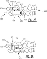
- Figure 2(E) shows a variant in which the upper coupling element is provided with a vertical portion 414 with a convex surface 415 directed toward the front teeth 440. This convex surface thus forms on one side a stop 413 for contact portion 407 which prevents the closing movement and on the other a guide surface for guiding and limiting the vertical movement of part 407 which is provided with a complementary surface 412/416.
- figure 2(F) shows a variant in which the horizontal adjusting means 511 are provided in upper coupling element 506 between a fixed part 508 mounted on the upper part and a stop part with a vertical portion 514 and with a stop 513.
- the vertical adjusting means 510 are provided in lower coupling element 505 between a contact portion 507 and a fixed part 509.
Landscapes
- Health & Medical Sciences (AREA)
- Otolaryngology (AREA)
- Pulmonology (AREA)
- Nursing (AREA)
- Orthopedic Medicine & Surgery (AREA)
- Engineering & Computer Science (AREA)
- Biomedical Technology (AREA)
- Heart & Thoracic Surgery (AREA)
- Vascular Medicine (AREA)
- Life Sciences & Earth Sciences (AREA)
- Animal Behavior & Ethology (AREA)
- General Health & Medical Sciences (AREA)
- Public Health (AREA)
- Veterinary Medicine (AREA)
- Orthopedics, Nursing, And Contraception (AREA)
- Respiratory Apparatuses And Protective Means (AREA)
Description
- The present invention relates to a device for treating breathing problems, comprising
- a lower part mountable on the lower jaw and an upper part mountable on the upper jaw, which lower and upper parts are situated at least in the vicinity of the back teeth; and
- left and right coupling means for coupling the lower part to the upper part close to the back teeth; wherein each of the left and right coupling means comprises an upper coupling element connected to the upper part and a lower coupling element connected to the lower part; which left and right coupling means are adapted to move the lower jaw forward in relation to the upper jaw.
- Night-time breathing problems, which can for instance result in snoring, sleep apnoea syndrome or other sleep disorders are a generally known problem. When a person sleeps, the rear part of the tongue may tend to slide backwards, whereby the pharyngeal airway is wholly or partially closed off. It is known to solve such breathing problems with a device which can be placed in the mouth and with which the lower jaw is placed further forward in relation to the upper jaw. The neck muscles are hereby forced into a tensioned position, whereby the tongue moves forward and the airway is left clear.
- Said devices placeable in the mouth are generally known and can be found in a number of different embodiments, including embodiments as described in the preamble which have been known since the 1990s. The known embodiments have the drawback that they allow too much freedom of movement during opening/closing of the mouth.
-
US 2007/0283967 andWO 2007/113465 both describe oral appliances in which coupling means are provided between the lower and upper tooth arches. Such appliances prevent the tongue being in a position of rest and offer only limited possibilities for control. - The invention has for its object to provide a device according to the preamble of
claim 1, which is user-friendly and agreeable to wear, and allows a precise adjustment with a limited freedom of movement of the lower jaw in relation to the upper jaw. - The invention is distinguished for this purpose by the features of the characterizing portion of
claim 1. The upper coupling element is provided with a stop for co-action with a contact surface of the lower coupling element, such that when lower and upper jaw are moved towards each other a further closing of the mouth is prevented when the contact surface comes up against the stop. The left and right, upper and lower coupling elements are further connected to respectively the upper and lower part such that they are situated in the oral vestibule (vestibulum oris) in the position of the device placed in the mouth, i.e. the coupling elements are situated between the teeth and respectively the left and right cheek. - In this way the freedom of movement of the lower jaw in relation to the upper jaw is also limited in vertical direction, i.e. in a direction substantially perpendicular to the plane of the lower jaw or upper jaw.
- According to an advantageous embodiment, at least one coupling element of the upper and the lower coupling elements is provided with vertical adjusting means for adjusting the vertical position of the stop/the contact surface in relation to the lower jaw in order to obtain an adjustable minimum distance between lower jaw and upper jaw.
- According to an aspect of the invention, the at least one coupling element comprises a contact portion and a base portion connected respectively to the upper or lower part, wherein vertical adjusting means are provided between the contact portion and the base portion for the purpose of adjusting the vertical position of the contact portion in relation to the base portion. By increasing the distance between the contact portion and the base portion the contact portion (on which the contact surface or the stop is situated) thus comes to lie further from respectively the upper part or the lower part, and the freedom of movement is thus further limited.
- According to a possible embodiment, the adjusting means comprise a substantially vertical adjusting screw with double screw thread for the up/downward adjustment of the contact portion in relation to the base portion, which adjusting screw co-acts at one outer end with a first threaded bore in the contact portion and co-acts at its other outer end with a second threaded bore in the base portion, wherein a rotation of the adjusting screw changes the distance between the first and second threaded bore. According to a further developed embodiment, the adjusting screw is provided substantially in the centre with an encircling flange with radially directed openings into which a rod fits for the purpose of rotating the adjusting screw by rotating the rod. In this way the vertical distance can be adjusted in convenient manner. Telescopically acting tubes between base portion and contact portion can further be provided on either side of the vertical adjusting screw so as to thus improve the stability of the device.
- According to another aspect of the invention, at least one coupling element of the upper and the lower coupling element comprises a fixed part which is connected to respectively the lower part or upper part, and a part which is displaceable relative to this fixed part substantially parallel to respectively the lower part or upper part. "Parallel to respectively the lower part or upper part" should be understood to mean substantially parallel to the plane of respectively the lower teeth or the upper teeth when the device is placed in the mouth. In this way the moving forward of the lower jaw in relation to the upper jaw can likewise be adjusted.
- According to a possible embodiment, the displaceable part comprises the contact portion such that both a horizontal and vertical displacement are possible. Horizontal should here be understood to mean substantially parallel to the plane of respectively the lower teeth or the upper teeth when the device is placed in the mouth, depending on whether the displaceable part is situated in respectively the upper or lower coupling element. Vertical should then be understood to mean substantially perpendicular to respectively the plane of the lower jaw or of the upper jaw.
- Each upper coupling element is provided with a substantially vertical portion with a concave or convex surface directed toward the front teeth, and each lower coupling element is provided with a substantially complementarily shaped surface, this such that the upper coupling element can engage in the lower coupling element and that rearward movement of the lower jaw is avoided. In this way the vertical movement of upper coupling element in relation to lower coupling element is further guided and limited, while a lateral movement of upper jaw in relation to lower jaw is a possibility, as will be further elucidated.
- According to a preferred embodiment of the invention, the upper and lower coupling elements are designed such that a limited lateral or sideways movement of the lower part arranged on the lower jaw in relation to the upper part arranged on the upper jaw, i.e. a movement in the plane of the teeth and substantially perpendicularly of the back teeth, is possible. A limited lateral freedom of movement further increases the wearing comfort without having serious consequences for the accuracy of adjustment. According to a possible embodiment, the lower coupling element lies in lateral direction at a distance from the upper part in the position of the device placed in the mouth.
- Other features and advantages will become apparent from the description of a number of non-limitative exemplary embodiments with reference to the accompanying drawings, in which:
-
figure 1 shows a perspective view of a preferred embodiment of a device according to the invention; -
figures 2(A)-(F) show schematic side views of different variants of the embodiment offigure 1 ; -
figure 3 (A) shows a perspective detail view of an upper coupling element of the embodiment offigure 1 ; -
figure 3(B) shows a perspective detail view of a lower coupling element of the embodiment offigure 1 ; -
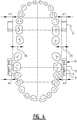
figure 4 shows a top view of the upper and lower coupling element placed on an upper and lower jaw. - In the drawings of the different embodiments equivalent components are designated with the same reference numerals, wherein a hundred is added at a time for each variant.
-
Figure 1 andfigures 3(A) &(B) andfigure 4 illustrate a preferred embodiment of anoral apparatus 1 for treating breathing problems. Thisapparatus 1 comprises a lower part mountable on the lower jaw in the form of a shaped part 2 and an upper part mountable on the upper jaw in the form of ashaped part 3. The skilled person will understand that the lower and upper part may also be embodied differently and the term part is understood to mean for instance a brace with a palate plate as well as a flexible bite-block. The only requirement is that the lower and upper parts are situated at least in the vicinity of the back teeth such that coupling elements can there be mounted on the lower/upper part 2, 3. - The apparatus further comprises left and right coupling means 4 (for the sake of simplicity only the left coupling means are shown in
figure 1 ) for coupling lower part 2 toupper part 3 close to the back teeth. Each of the left and right coupling means 4 comprises anupper coupling element 6 connected toupper part 3 and alower coupling element 5 connected to lower part 2. In the position of lower and upper part placed in the mouth these coupling means 4 are situated on the vestibular side of the tooth arch, i.e. between the cheek and the tooth arches. As will become further apparent, the left and right coupling means 4 are adapted to move the lower jaw forward in relation to the upper jaw, while the up/downward movement of the lower jaw in relation to upper jaw is also controlled. - In the embodiment of
figure 1 lower coupling element 5 consists of three parts: afixed part 9, acentral part 8, and anupper part 7. Fixedpart 9 is attached to lower part 2 and connected via horizontal adjusting means 11 tocentral part 8.Central part 8 is connected via vertical adjusting means 10 toupper part 7.Part 7 functions here as a contact portion with acontact surface 12 for the purpose of making contact with astop 13 ofupper coupling element 6 when the mouth is closed.Parts Contact portion 7 can be moved upward/downward in relation tobase portion -
Central part 8 is further horizontally displaceable in relation to fixedpart 9 via adjusting means 11, wherein horizontally is understood to mean substantially parallel to lower part 2.Parts fixed part 9.Parts contact surface 12 in order to obtain an adjustable minimum vertical and horizontal distance between lower jaw and upper jaw. -
Upper coupling element 6 is provided with a substantiallyvertical portion 14 with aconcave surface 15 directed toward the front teeth, andcontact portion 7 oflower coupling element 5 is provided with a substantially complementarilyshaped surface 16. In this way the upper coupling element can engage in the lower coupling element and the vertical movement of lower jaw in relation to upper jaw is further guided and limited. - According to the illustrated embodiment, the vertical and horizontal adjusting means 10, 11 consist in each case of a central adjusting
screw contact portion 7 relative to fixedpart 9. Arranged on either side of each central adjustingscrew acting tubes figure 3(B) ). The central vertical adjustingscrew 17 co-acts at one outer end with a first threaded bore incontact portion 7 and at its other outer end with a second threaded bore incentral part 8, wherein a rotation of the adjusting screw changes the distance between the first and second threaded bore. The central horizontal adjustingscrew 18 co-acts on one side with a threaded bore incentral part 8 and on the other with a threaded bore infixed part 9. Each adjustingscrew encircling flange 21 with radially directedopenings 20 into which a rod fits for the purpose of rotating the adjusting screw by rotating the rod. -
Figure 3(A) showsupper coupling element 6 in detail. The dimensions of thiselement 6 can for instance be as follows: - width w1 between 5 and 10 mm, preferably about 8 mm;
- height h1 between 10 and 20 mm, preferably about 15 mm;
-
length 11 between 10 and 20 mm, preferably about 15 mm.Figure 3(B) showslower coupling element 5 in detail. The dimensions of thiselement 5 can for instance be as follows: - width w2 smaller than width w1, for instance between 4 and 9 mm, preferably about 2 mm smaller than w1 and so more preferably about 6 mm;
- height h2 between 15 and 25 mm, preferably about 18 mm;
-
length 12 between 20 and 40 mm, preferably about 32 mm. - According to an advantageous embodiment, each
upper coupling element 6 can move laterally or sideways in limited manner (seearrow 30 infigure 4 ) in relation to the lower coupling element in a position of the oral apparatus placed in the mouth. In an advantageous embodiment shown infigure 4 the width w2 ofupper coupling element 6 is for this purpose smaller than the width w1 oflower coupling element 5, and the lower coupling element is placed further outward (here over a distance w1-w2, although the skilled person will appreciate that this distance may also be to some extent smaller or greater). In this waylower coupling element 5 will be situated at a distance in lateral direction from the upper part when the device is placed in the mouth, and will thus allow a lateral movement of upper part in relation to lower part. - A number of variants will now be described with reference to the schematic side views shown in
figures 2(A)-(E) , in which for the sake of clarity the lower and upper parts are not shown. - In the variant of
figure 2(A) no horizontal adjusting means are provided andlower coupling element 105 consists of two parts: abase portion 109 and acontact portion 107.Contact portion 107 has acontact surface 112, the height of which is adjustable using vertical adjusting means 110.Figure 2(B) shows an equivalent variant whereinbase portion 209 and the verticallyadjustable contact portion 207 are provided inupper coupling element 206 and stop 213 is situated on the bottom ofcontact portion 207, whilecontact surface 212 is provided onlower coupling element 205. - The variant of
figure 2(C) largely corresponds with the embodiment offigure 1 , so that reference can be made to the description above offigure 1 .Figure 2(D) shows a reverse variant in whichparts upper coupling element 306.Lower coupling element 305 is provided here with avertical portion 314 with aconvex surface 315 andcontact portion 307 is formed with a complementarily formedsurface 316. -
Figure 2(E) shows a variant in which the upper coupling element is provided with avertical portion 414 with a convex surface 415 directed toward thefront teeth 440. This convex surface thus forms on one side a stop 413 forcontact portion 407 which prevents the closing movement and on the other a guide surface for guiding and limiting the vertical movement ofpart 407 which is provided with acomplementary surface 412/416. Finally,figure 2(F) shows a variant in which the horizontal adjusting means 511 are provided inupper coupling element 506 between afixed part 508 mounted on the upper part and a stop part with avertical portion 514 and with astop 513. The vertical adjusting means 510 are provided inlower coupling element 505 between acontact portion 507 and a fixed part 509. - The skilled person will appreciate that the figures are not limitative and that measures of one variant may be added to another variant without departing from the scope of the invention. The design of
element element 507 on the other of the embodiment offigure 2F , can for instance thus be modified and be for instance analogous to the design ofelement element 7 on the other of the embodiment offigure 1 . - The invention is not limited to the exemplary embodiments illustrated above and the skilled person will understand that many modifications can be envisaged without departing from the scope of the invention, this scope being defined solely by the following claims.
Claims (10)
- Device for treating breathing problems, comprising- a lower part (2) mountable on the lower jaw and an upper part (3) mountable on the upper jaw, which lower and upper parts are adapted to be situated at least in the vicinity of the back teeth; and- left and right coupling means (4) for coupling the lower part to the upper part close to the back teeth; wherein each of the left and right coupling means comprises an upper coupling element (6) connected to the upper part and a lower coupling element connected to the lower part (5); which left and right coupling means are adapted to move the lower jaw forward in relation to the upper jaw; wherein the upper coupling element is provided with a stop (13) for co-action with a contact surface (12) of the lower coupling element; and wherein each upper coupling element (5, 6) is provided with a portion with a concave or convex surface (15) directed toward the front teeth, and that each lower coupling element is provided with a complementarily shaped surface (16), this such that the upper coupling element can engage in the lower coupling element and that rearward movement of the lower jaw is avoided; characterized in that the upper and lower coupling elements (5, 6) are connected to respectively the upper and lower part such that these upper and lower coupling elements are situated in the oral vestibule in the position of the device placed in the mouth, and in that said stop (13) and said contact surface (12) are located in the oral vestibule, on the vestibular side of the tooth arch, in the position of the device placed in the mouth, such that when lower jaw and upper jaw are moved toward each other a further closing of the mouth is prevented when the contact surface comes up against the stop.
- Device as claimed in claim 1, characterized in that at least one coupling element of the upper and the lower coupling element is provided with vertical adjusting means (10) for adjusting the vertical position of the contact surface/stop in relation to the lower jaw in order to obtain an adjustable minimum distance between lower jaw and upper jaw.
- Device as claimed in claim 2, characterized in that the at least one coupling element of the upper and the lower coupling element comprises a contact portion (7) and a base portion (8, 9) connected to the upper or lower part, and that the vertical adjusting means (10) are provided between the contact portion and the base portion for the purpose of adjusting the vertical position of the contact portion in relation to the base portion.
- Device as claimed in claim 3, characterized in that the adjusting means (10) comprise a substantially vertical adjusting screw with double screw thread for the up/downward adjustment of the contact portion in relation to the base portion, which adjusting screw co-acts at one outer end with a first threaded bore in the contact portion and co-acts at its other outer end with a second threaded bore in the base portion, wherein a rotation of the adjusting screw changes the distance between the first and second threaded bore.
- Device as claimed in claim 4, characterized in that the adjusting screw is provided substantially in the centre with an encircling flange with radially directed openings into which a rod fits for the purpose of rotating the adjusting screw by rotating the rod.
- Device as claimed in claim 4 or 5, characterized in that telescopically acting tubes between base portion and contact portion are provided on either side of the vertical adjusting screw.
- Device as claimed in any of the foregoing claims, characterized in that at least one coupling element of the upper and the lower coupling element comprises a fixed part (9) which is connected to respectively the lower part or upper part, and a part (7, 8) which is displaceable relative to this fixed part parallel to respectively the lower part or upper part.
- Device as claimed in claim 7, characterized in that the displaceable part (7, 8) comprises the contact surface (12).
- Device as claimed in any of the foregoing claims, characterized in that each lower coupling element has in lateral direction a width differing from the associated upper coupling element such that a lateral clearance is obtained which allows a lateral movement of the lower jaw in relation to the upper jaw, wherein a limited lateral or sideways movement of the lower part arranged on the lower jaw in relation to the upper part arranged on the upper jaw, i.e. a movement in the plane of the teeth and substantially perpendicularly of the back teeth, is possible.
- Device as claimed in any of the foregoing claims, characterized in that both for the left and the right coupling means, one coupling element of the upper and lower coupling element is situated in lateral direction at a distance from the opposite lower or upper part in the position of the device placed in the mouth.
Applications Claiming Priority (2)
| Application Number | Priority Date | Filing Date | Title |
|---|---|---|---|
| BE2008/0374A BE1018209A5 (en) | 2008-07-07 | 2008-07-07 | DEVICE FOR TREATING NIGHT-BREATHING RESPIRATORY PROBLEMS. |
| PCT/BE2009/000037 WO2010003198A2 (en) | 2008-07-07 | 2009-07-06 | Device for treating night time breathing problems |
Publications (2)
| Publication Number | Publication Date |
|---|---|
| EP2331036A2 EP2331036A2 (en) | 2011-06-15 |
| EP2331036B1 true EP2331036B1 (en) | 2019-11-06 |
Family
ID=40380009
Family Applications (1)
| Application Number | Title | Priority Date | Filing Date |
|---|---|---|---|
| EP09775649.8A Active EP2331036B1 (en) | 2008-07-07 | 2009-07-06 | Device for treating night time breathing problems |
Country Status (10)
| Country | Link |
|---|---|
| US (1) | US8517029B2 (en) |
| EP (1) | EP2331036B1 (en) |
| JP (1) | JP2011526821A (en) |
| CN (1) | CN102112072B (en) |
| AU (1) | AU2009267736B2 (en) |
| BE (1) | BE1018209A5 (en) |
| BR (1) | BRPI0915476A2 (en) |
| CA (1) | CA2729913A1 (en) |
| IL (1) | IL210441A0 (en) |
| WO (1) | WO2010003198A2 (en) |
Families Citing this family (49)
| Publication number | Priority date | Publication date | Assignee | Title |
|---|---|---|---|---|
| US7748386B2 (en) | 2006-04-06 | 2010-07-06 | Thornton W Keith | Oral appliance for treating a breathing condition |
| US8316857B2 (en) * | 2006-04-06 | 2012-11-27 | Airway Technologies, Llc | Oral appliance for treating a breathing condition |
| US8316858B2 (en) * | 2006-04-06 | 2012-11-27 | Airway Technologies, Llc | System for coupling an oral appliance to a medical mask |
| US8607796B2 (en) | 2009-02-27 | 2013-12-17 | Airway Technologies, Llc | Apparatus and method for coupling an oral appliance to a gas delivery device |
| US8573224B2 (en) | 2009-10-16 | 2013-11-05 | Airway Technologies, Llc | Custom-molded oral appliance and method of forming |
| WO2012138459A1 (en) | 2011-04-05 | 2012-10-11 | Airway Technologies, Llc | Oral appliance for treating particular disorders associated with sleep |
| US8671946B2 (en) | 2011-04-05 | 2014-03-18 | Airway Technologies, Llc | Custom dental appliance and method of creating a custom dental appliance |
| US8783261B2 (en) | 2011-04-05 | 2014-07-22 | Airway Technologies, Llc | Apparatus for prevention of snoring and improved breathing |
| US8662084B2 (en) | 2011-04-05 | 2014-03-04 | Airway Technologies, Llc | Universal oral appliance with a universal coupler |
| US20130112210A1 (en) * | 2011-11-03 | 2013-05-09 | Ivan F. STEIN | Oral Sleep Apnea Device |
| USD718449S1 (en) * | 2011-11-23 | 2014-11-25 | Somnomed Limited | Set of oral appliances |
| USD718448S1 (en) * | 2011-11-23 | 2014-11-25 | Somnomed Limited | Set of oral appliances |
| SE538339C2 (en) | 2012-06-19 | 2016-05-24 | Dental Device Sweden Ab | Device for the treatment of sleep apnea or snoring |
| USD704843S1 (en) * | 2012-06-29 | 2014-05-13 | Gurdev Dave Singh | Sleep appliance |
| WO2014189540A1 (en) | 2012-10-16 | 2014-11-27 | Catalano Peter J | Method and apparatus for treating obstructive sleep apnea (osa) |
| US10166017B2 (en) | 2013-08-05 | 2019-01-01 | Cook Medical Technologies Llc | Medical devices having a releasable tubular member and methods of using the same |
| US20150075540A1 (en) * | 2013-09-17 | 2015-03-19 | Brian Douglas Dye | Apparatus for the prevention of sleep apnea |
| CN104688404A (en) * | 2013-12-04 | 2015-06-10 | 肯尼斯·卢科 | An oral appliance for treating obstructive sleep apnea (OSA) and sleep bruxism |
| CA2939102A1 (en) * | 2014-02-13 | 2015-08-20 | Silverfox Dental & Ortho, Llc | Oral motion preservation device |
| US9974563B2 (en) | 2014-05-28 | 2018-05-22 | Cook Medical Technologies Llc | Medical devices having a releasable member and methods of using the same |
| EP3164102B1 (en) * | 2014-07-02 | 2025-01-22 | Odin Sleep, LLC | Sleep apnea oral appliance for use during orthodontic treatment |
| US9913661B2 (en) | 2014-08-04 | 2018-03-13 | Cook Medical Technologies Llc | Medical devices having a releasable tubular member and methods of using the same |
| US10376408B2 (en) | 2014-08-25 | 2019-08-13 | Airway Technologies, Llc | Oral appliance |
| US11426304B2 (en) | 2014-08-25 | 2022-08-30 | Airway Technologies, Llc | Oral appliance |
| US10828131B2 (en) | 2014-12-16 | 2020-11-10 | R.I.P., Llc | Adjustable sleep apnea oral appliance |
| US10258319B2 (en) | 2015-05-18 | 2019-04-16 | Richard L. Arden | Airway assist device and method |
| US10010313B2 (en) | 2015-05-18 | 2018-07-03 | Richard L. Arden | Mandibular subluxation device and method |
| US10342526B2 (en) | 2015-07-01 | 2019-07-09 | Richard L. Arden | Airway assist device and method |
| GB201602386D0 (en) * | 2015-07-08 | 2016-03-23 | Aria Healthcare Ltd | Improvements to oral devices |
| US9655695B2 (en) * | 2015-08-06 | 2017-05-23 | Gregory K. Ross | Oral apparatuses and methods for mandibular jaw manipulation |
| US20170042725A1 (en) * | 2015-08-12 | 2017-02-16 | Silverfox Dental & Ortho, Llc | Oral motion preservation device |
| JP6903343B2 (en) | 2015-11-30 | 2021-07-14 | セラン プロダクツ, インコーポレイテッドSelane Products, Inc. | Adjustable sleep apnea oral device |
| US10265213B2 (en) * | 2016-03-25 | 2019-04-23 | Jae Il Lim | Temporomandibular joint correction apparatus with exchangeable adjustor |
| JP6726741B2 (en) * | 2016-06-28 | 2020-07-22 | 三井化学株式会社 | Mouthpiece |
| CN110087590B (en) * | 2016-12-27 | 2022-04-15 | 三井化学株式会社 | Tooth protector |
| USD827835S1 (en) * | 2017-02-22 | 2018-09-04 | Philip Bocala | Oral sleep apnea and snoring device |
| US10603207B2 (en) * | 2017-07-17 | 2020-03-31 | ProSomnus Sleep Technologies, Inc. | Mandibular advancement device with guide channel |
| US11400244B2 (en) | 2017-10-20 | 2022-08-02 | Beck Medical, Ltd. | Nasal device for treatment |
| USD870894S1 (en) | 2018-07-19 | 2019-12-24 | Greg Ross | Jaw manipulation appliance |
| CN110547904A (en) * | 2019-10-05 | 2019-12-10 | 扬州市君瑞企业管理有限公司 | Simple snore preventing device for hospital physiotherapy and rehabilitation |
| US11484434B2 (en) * | 2019-11-15 | 2022-11-01 | Raghavendra Vitthalrao GHUGE | Dynamic mandibular and lingual repositioning devices, controller station, and methods of treating and/or diagnosing medical disorders |
| US20210145630A1 (en) * | 2019-11-15 | 2021-05-20 | Raghavendra Vitthalrao GHUGE | Maxillary and mandibular devices, controller station, and methods of treating and/or diagnosing medical disorders |
| US11666478B2 (en) | 2019-11-15 | 2023-06-06 | Sleep Solutions Of Texas, Llc | Maxillary devices, controller station, and methods of treating and/or diagnosing medical disorders |
| USD932626S1 (en) | 2020-05-13 | 2021-10-05 | ProSomnus Sleep Technologies, Inc. | Mandibular advancement device with comfort bumps |
| WO2022104354A1 (en) * | 2020-11-14 | 2022-05-19 | Ghuge Raghavendra Vitthalrao | Maxillary and mandibular devices, controller station |
| IT202100015263A1 (en) * | 2021-06-11 | 2022-12-11 | Fabrizio Anelli | MANDIBULAR ADVANCEMENT DEVICE TO TREAT SLEEP APNEA AND SPACER KIT FOR A MANDIBULAR ADVANCEMENT DEVICE |
| US12318325B2 (en) * | 2021-07-02 | 2025-06-03 | Sleep Solutions Of Texas, Llc | Maxillary and mandibular devices that prevent disengagement therebetween, controller station, and methods of treating and/or diagnosing medical disorders |
| US11806273B2 (en) | 2021-07-02 | 2023-11-07 | Sleep Solutions Of Texas, Llc | Maxillary and mandibular devices that increase the smallest concentric airway cross-sectional area of a user for improvements during physical activities |
| US12403033B2 (en) * | 2023-04-21 | 2025-09-02 | Achaemenid, Llc | Oral appliance for the treatment of sleep apnea |
Family Cites Families (11)
| Publication number | Priority date | Publication date | Assignee | Title |
|---|---|---|---|---|
| US5868138A (en) * | 1993-04-13 | 1999-02-09 | Silent Knight Ventures, Inc. | Dental appliance for treatment of snoring and obstructive sleep apnea |
| AUPP450598A0 (en) * | 1998-07-06 | 1998-07-30 | Palmisano, Richard George | A mandibular advancement device |
| CN1091366C (en) * | 1999-04-21 | 2002-09-25 | 卢崇伟 | Snore treating device |
| US7007697B1 (en) * | 2003-06-16 | 2006-03-07 | Nicholas Della Grotta | Respiration assisting and snore reducing apparatus |
| BE1015642A3 (en) * | 2003-08-08 | 2005-07-05 | Nelissen Jozef Frans | Device for the treatment of nocturnal breathing problems. |
| DE502004007207D1 (en) * | 2003-09-16 | 2008-07-03 | Hinz Labor Fachlaboratorium Fu | Intraoral therapy device |
| GB2438832B (en) * | 2006-04-04 | 2009-03-04 | Sleepworks Products Ltd | Device to reduce snoring and sleep apnoea |
| US7637262B2 (en) * | 2006-06-12 | 2009-12-29 | Bailey Dennis R | Anti-retrusion oral appliance |
| KR100787188B1 (en) * | 2006-11-17 | 2007-12-21 | 이승규 | Snoring Mechanism |
| DE102007013879A1 (en) * | 2007-03-20 | 2008-09-25 | Bredent Gmbh & Co. Kg | Biocompatible treatment device for the treatment of snoring and sleep-related respiratory disorders |
| CN201157439Y (en) * | 2008-01-25 | 2008-12-03 | 宋冬生 | Snore inhibitor |
-
2008
- 2008-07-07 BE BE2008/0374A patent/BE1018209A5/en active
-
2009
- 2009-07-06 AU AU2009267736A patent/AU2009267736B2/en not_active Expired - Fee Related
- 2009-07-06 EP EP09775649.8A patent/EP2331036B1/en active Active
- 2009-07-06 CA CA2729913A patent/CA2729913A1/en not_active Abandoned
- 2009-07-06 BR BRPI0915476A patent/BRPI0915476A2/en not_active Application Discontinuation
- 2009-07-06 CN CN2009801305220A patent/CN102112072B/en not_active Expired - Fee Related
- 2009-07-06 US US13/002,499 patent/US8517029B2/en active Active
- 2009-07-06 WO PCT/BE2009/000037 patent/WO2010003198A2/en not_active Ceased
- 2009-07-06 JP JP2011516929A patent/JP2011526821A/en active Pending
-
2011
- 2011-01-03 IL IL210441A patent/IL210441A0/en unknown
Non-Patent Citations (1)
| Title |
|---|
| None * |
Also Published As
| Publication number | Publication date |
|---|---|
| BE1018209A5 (en) | 2010-07-06 |
| BRPI0915476A2 (en) | 2016-09-06 |
| CA2729913A1 (en) | 2010-01-14 |
| US8517029B2 (en) | 2013-08-27 |
| WO2010003198A3 (en) | 2010-05-14 |
| JP2011526821A (en) | 2011-10-20 |
| CN102112072A (en) | 2011-06-29 |
| AU2009267736A1 (en) | 2010-01-14 |
| CN102112072B (en) | 2013-08-28 |
| AU2009267736B2 (en) | 2014-05-15 |
| IL210441A0 (en) | 2011-03-31 |
| US20110168187A1 (en) | 2011-07-14 |
| EP2331036A2 (en) | 2011-06-15 |
| WO2010003198A2 (en) | 2010-01-14 |
Similar Documents
| Publication | Publication Date | Title |
|---|---|---|
| EP2331036B1 (en) | Device for treating night time breathing problems | |
| JP4709146B2 (en) | Device for treating nocturnal breathing disorders | |
| KR101943146B1 (en) | Occlusal splint arrangement | |
| EP0746288B1 (en) | Apparatus for preventing snoring and improving breathing | |
| US7637262B2 (en) | Anti-retrusion oral appliance | |
| US20080072915A1 (en) | Device for treating nighttime breathing problems | |
| CN110087590B (en) | Tooth protector | |
| US20080115791A1 (en) | Mandibular Advancement Mouthpiece, An Intraoccusal Removable Improved Device For Eliminating Or Reducing Snoring | |
| KR101782093B1 (en) | Prevention instrument for snore and bruxism | |
| US20080210244A1 (en) | Sleep appliance | |
| CA2651916A1 (en) | Sleep appliance | |
| KR20120077985A (en) | Apparatus for preventing from snoring with an snoring relative seriousness of subject | |
| US20110120476A1 (en) | Sleep appliance | |
| EP2181678A1 (en) | An oral orthesis for reducing snoring and sleep apnea symptoms | |
| WO2011146419A1 (en) | Oral appliance with adjustment assembly | |
| TWI737347B (en) | Mandible displacement adjusting device |
Legal Events
| Date | Code | Title | Description |
|---|---|---|---|
| PUAI | Public reference made under article 153(3) epc to a published international application that has entered the european phase |
Free format text: ORIGINAL CODE: 0009012 |
|
| 17P | Request for examination filed |
Effective date: 20110117 |
|
| AK | Designated contracting states |
Kind code of ref document: A2 Designated state(s): AT BE BG CH CY CZ DE DK EE ES FI FR GB GR HR HU IE IS IT LI LT LU LV MC MK MT NL NO PL PT RO SE SI SK SM TR |
|
| AX | Request for extension of the european patent |
Extension state: AL BA RS |
|
| DAX | Request for extension of the european patent (deleted) | ||
| 17Q | First examination report despatched |
Effective date: 20150409 |
|
| STAA | Information on the status of an ep patent application or granted ep patent |
Free format text: STATUS: EXAMINATION IS IN PROGRESS |
|
| GRAP | Despatch of communication of intention to grant a patent |
Free format text: ORIGINAL CODE: EPIDOSNIGR1 |
|
| STAA | Information on the status of an ep patent application or granted ep patent |
Free format text: STATUS: GRANT OF PATENT IS INTENDED |
|
| INTG | Intention to grant announced |
Effective date: 20190703 |
|
| GRAS | Grant fee paid |
Free format text: ORIGINAL CODE: EPIDOSNIGR3 |
|
| GRAA | (expected) grant |
Free format text: ORIGINAL CODE: 0009210 |
|
| STAA | Information on the status of an ep patent application or granted ep patent |
Free format text: STATUS: THE PATENT HAS BEEN GRANTED |
|
| AK | Designated contracting states |
Kind code of ref document: B1 Designated state(s): AT BE BG CH CY CZ DE DK EE ES FI FR GB GR HR HU IE IS IT LI LT LU LV MC MK MT NL NO PL PT RO SE SI SK SM TR |
|
| REG | Reference to a national code |
Ref country code: GB Ref legal event code: FG4D |
|
| REG | Reference to a national code |
Ref country code: AT Ref legal event code: REF Ref document number: 1197771 Country of ref document: AT Kind code of ref document: T Effective date: 20191115 Ref country code: CH Ref legal event code: EP |
|
| REG | Reference to a national code |
Ref country code: IE Ref legal event code: FG4D |
|
| REG | Reference to a national code |
Ref country code: DE Ref legal event code: R096 Ref document number: 602009060366 Country of ref document: DE |
|
| REG | Reference to a national code |
Ref country code: LT Ref legal event code: MG4D |
|
| PG25 | Lapsed in a contracting state [announced via postgrant information from national office to epo] |
Ref country code: FI Free format text: LAPSE BECAUSE OF FAILURE TO SUBMIT A TRANSLATION OF THE DESCRIPTION OR TO PAY THE FEE WITHIN THE PRESCRIBED TIME-LIMIT Effective date: 20191106 Ref country code: BG Free format text: LAPSE BECAUSE OF FAILURE TO SUBMIT A TRANSLATION OF THE DESCRIPTION OR TO PAY THE FEE WITHIN THE PRESCRIBED TIME-LIMIT Effective date: 20200206 Ref country code: SE Free format text: LAPSE BECAUSE OF FAILURE TO SUBMIT A TRANSLATION OF THE DESCRIPTION OR TO PAY THE FEE WITHIN THE PRESCRIBED TIME-LIMIT Effective date: 20191106 Ref country code: LV Free format text: LAPSE BECAUSE OF FAILURE TO SUBMIT A TRANSLATION OF THE DESCRIPTION OR TO PAY THE FEE WITHIN THE PRESCRIBED TIME-LIMIT Effective date: 20191106 Ref country code: LT Free format text: LAPSE BECAUSE OF FAILURE TO SUBMIT A TRANSLATION OF THE DESCRIPTION OR TO PAY THE FEE WITHIN THE PRESCRIBED TIME-LIMIT Effective date: 20191106 Ref country code: PL Free format text: LAPSE BECAUSE OF FAILURE TO SUBMIT A TRANSLATION OF THE DESCRIPTION OR TO PAY THE FEE WITHIN THE PRESCRIBED TIME-LIMIT Effective date: 20191106 Ref country code: GR Free format text: LAPSE BECAUSE OF FAILURE TO SUBMIT A TRANSLATION OF THE DESCRIPTION OR TO PAY THE FEE WITHIN THE PRESCRIBED TIME-LIMIT Effective date: 20200207 Ref country code: PT Free format text: LAPSE BECAUSE OF FAILURE TO SUBMIT A TRANSLATION OF THE DESCRIPTION OR TO PAY THE FEE WITHIN THE PRESCRIBED TIME-LIMIT Effective date: 20200306 Ref country code: NO Free format text: LAPSE BECAUSE OF FAILURE TO SUBMIT A TRANSLATION OF THE DESCRIPTION OR TO PAY THE FEE WITHIN THE PRESCRIBED TIME-LIMIT Effective date: 20200206 Ref country code: ES Free format text: LAPSE BECAUSE OF FAILURE TO SUBMIT A TRANSLATION OF THE DESCRIPTION OR TO PAY THE FEE WITHIN THE PRESCRIBED TIME-LIMIT Effective date: 20191106 |
|
| REG | Reference to a national code |
Ref country code: NL Ref legal event code: FP |
|
| PG25 | Lapsed in a contracting state [announced via postgrant information from national office to epo] |
Ref country code: IS Free format text: LAPSE BECAUSE OF FAILURE TO SUBMIT A TRANSLATION OF THE DESCRIPTION OR TO PAY THE FEE WITHIN THE PRESCRIBED TIME-LIMIT Effective date: 20200306 Ref country code: HR Free format text: LAPSE BECAUSE OF FAILURE TO SUBMIT A TRANSLATION OF THE DESCRIPTION OR TO PAY THE FEE WITHIN THE PRESCRIBED TIME-LIMIT Effective date: 20191106 |
|
| PG25 | Lapsed in a contracting state [announced via postgrant information from national office to epo] |
Ref country code: RO Free format text: LAPSE BECAUSE OF FAILURE TO SUBMIT A TRANSLATION OF THE DESCRIPTION OR TO PAY THE FEE WITHIN THE PRESCRIBED TIME-LIMIT Effective date: 20191106 Ref country code: CZ Free format text: LAPSE BECAUSE OF FAILURE TO SUBMIT A TRANSLATION OF THE DESCRIPTION OR TO PAY THE FEE WITHIN THE PRESCRIBED TIME-LIMIT Effective date: 20191106 Ref country code: DK Free format text: LAPSE BECAUSE OF FAILURE TO SUBMIT A TRANSLATION OF THE DESCRIPTION OR TO PAY THE FEE WITHIN THE PRESCRIBED TIME-LIMIT Effective date: 20191106 Ref country code: EE Free format text: LAPSE BECAUSE OF FAILURE TO SUBMIT A TRANSLATION OF THE DESCRIPTION OR TO PAY THE FEE WITHIN THE PRESCRIBED TIME-LIMIT Effective date: 20191106 |
|
| REG | Reference to a national code |
Ref country code: DE Ref legal event code: R097 Ref document number: 602009060366 Country of ref document: DE |
|
| REG | Reference to a national code |
Ref country code: AT Ref legal event code: MK05 Ref document number: 1197771 Country of ref document: AT Kind code of ref document: T Effective date: 20191106 |
|
| PG25 | Lapsed in a contracting state [announced via postgrant information from national office to epo] |
Ref country code: SK Free format text: LAPSE BECAUSE OF FAILURE TO SUBMIT A TRANSLATION OF THE DESCRIPTION OR TO PAY THE FEE WITHIN THE PRESCRIBED TIME-LIMIT Effective date: 20191106 Ref country code: SM Free format text: LAPSE BECAUSE OF FAILURE TO SUBMIT A TRANSLATION OF THE DESCRIPTION OR TO PAY THE FEE WITHIN THE PRESCRIBED TIME-LIMIT Effective date: 20191106 |
|
| PLBE | No opposition filed within time limit |
Free format text: ORIGINAL CODE: 0009261 |
|
| STAA | Information on the status of an ep patent application or granted ep patent |
Free format text: STATUS: NO OPPOSITION FILED WITHIN TIME LIMIT |
|
| 26N | No opposition filed |
Effective date: 20200807 |
|
| PG25 | Lapsed in a contracting state [announced via postgrant information from national office to epo] |
Ref country code: SI Free format text: LAPSE BECAUSE OF FAILURE TO SUBMIT A TRANSLATION OF THE DESCRIPTION OR TO PAY THE FEE WITHIN THE PRESCRIBED TIME-LIMIT Effective date: 20191106 Ref country code: AT Free format text: LAPSE BECAUSE OF FAILURE TO SUBMIT A TRANSLATION OF THE DESCRIPTION OR TO PAY THE FEE WITHIN THE PRESCRIBED TIME-LIMIT Effective date: 20191106 |
|
| PG25 | Lapsed in a contracting state [announced via postgrant information from national office to epo] |
Ref country code: IT Free format text: LAPSE BECAUSE OF FAILURE TO SUBMIT A TRANSLATION OF THE DESCRIPTION OR TO PAY THE FEE WITHIN THE PRESCRIBED TIME-LIMIT Effective date: 20191106 |
|
| PG25 | Lapsed in a contracting state [announced via postgrant information from national office to epo] |
Ref country code: MC Free format text: LAPSE BECAUSE OF FAILURE TO SUBMIT A TRANSLATION OF THE DESCRIPTION OR TO PAY THE FEE WITHIN THE PRESCRIBED TIME-LIMIT Effective date: 20191106 |
|
| REG | Reference to a national code |
Ref country code: CH Ref legal event code: PL |
|
| PG25 | Lapsed in a contracting state [announced via postgrant information from national office to epo] |
Ref country code: IE Free format text: LAPSE BECAUSE OF NON-PAYMENT OF DUE FEES Effective date: 20200706 Ref country code: LI Free format text: LAPSE BECAUSE OF NON-PAYMENT OF DUE FEES Effective date: 20200731 Ref country code: CH Free format text: LAPSE BECAUSE OF NON-PAYMENT OF DUE FEES Effective date: 20200731 |
|
| PG25 | Lapsed in a contracting state [announced via postgrant information from national office to epo] |
Ref country code: TR Free format text: LAPSE BECAUSE OF FAILURE TO SUBMIT A TRANSLATION OF THE DESCRIPTION OR TO PAY THE FEE WITHIN THE PRESCRIBED TIME-LIMIT Effective date: 20191106 Ref country code: MT Free format text: LAPSE BECAUSE OF FAILURE TO SUBMIT A TRANSLATION OF THE DESCRIPTION OR TO PAY THE FEE WITHIN THE PRESCRIBED TIME-LIMIT Effective date: 20191106 Ref country code: CY Free format text: LAPSE BECAUSE OF FAILURE TO SUBMIT A TRANSLATION OF THE DESCRIPTION OR TO PAY THE FEE WITHIN THE PRESCRIBED TIME-LIMIT Effective date: 20191106 |
|
| PG25 | Lapsed in a contracting state [announced via postgrant information from national office to epo] |
Ref country code: MK Free format text: LAPSE BECAUSE OF FAILURE TO SUBMIT A TRANSLATION OF THE DESCRIPTION OR TO PAY THE FEE WITHIN THE PRESCRIBED TIME-LIMIT Effective date: 20191106 |
|
| REG | Reference to a national code |
Ref country code: LU Ref legal event code: HC Owner name: NELISSEN JOZEF FRANS; BE Free format text: FORMER OWNER: NELISSEN, JOZEF FRANS Effective date: 20231031 Ref country code: DE Ref legal event code: R081 Ref document number: 602009060366 Country of ref document: DE Owner name: NELISSEN, JOZEF FRANS, BE Free format text: FORMER OWNER: NELISSEN, JOZEF FRANS, NIJLEN, BE |
|
| PGFP | Annual fee paid to national office [announced via postgrant information from national office to epo] |
Ref country code: LU Payment date: 20250728 Year of fee payment: 17 Ref country code: NL Payment date: 20250726 Year of fee payment: 17 |
|
| PGFP | Annual fee paid to national office [announced via postgrant information from national office to epo] |
Ref country code: DE Payment date: 20250729 Year of fee payment: 17 |
|
| PGFP | Annual fee paid to national office [announced via postgrant information from national office to epo] |
Ref country code: BE Payment date: 20250728 Year of fee payment: 17 Ref country code: GB Payment date: 20250728 Year of fee payment: 17 |
|
| PGFP | Annual fee paid to national office [announced via postgrant information from national office to epo] |
Ref country code: FR Payment date: 20250725 Year of fee payment: 17 |