EP2330705A1 - Wire holder and wire bundling structure - Google Patents
Wire holder and wire bundling structure Download PDFInfo
- Publication number
- EP2330705A1 EP2330705A1 EP08877133A EP08877133A EP2330705A1 EP 2330705 A1 EP2330705 A1 EP 2330705A1 EP 08877133 A EP08877133 A EP 08877133A EP 08877133 A EP08877133 A EP 08877133A EP 2330705 A1 EP2330705 A1 EP 2330705A1
- Authority
- EP
- European Patent Office
- Prior art keywords
- wires
- recesses
- wire holder
- bundling
- wire
- Prior art date
- Legal status (The legal status is an assumption and is not a legal conclusion. Google has not performed a legal analysis and makes no representation as to the accuracy of the status listed.)
- Granted
Links
Images


Classifications
-
- H—ELECTRICITY
- H02—GENERATION; CONVERSION OR DISTRIBUTION OF ELECTRIC POWER
- H02G—INSTALLATION OF ELECTRIC CABLES OR LINES, OR OF COMBINED OPTICAL AND ELECTRIC CABLES OR LINES
- H02G3/00—Installations of electric cables or lines or protective tubing therefor in or on buildings, equivalent structures or vehicles
- H02G3/30—Installations of cables or lines on walls, floors or ceilings
-
- H—ELECTRICITY
- H02—GENERATION; CONVERSION OR DISTRIBUTION OF ELECTRIC POWER
- H02G—INSTALLATION OF ELECTRIC CABLES OR LINES, OR OF COMBINED OPTICAL AND ELECTRIC CABLES OR LINES
- H02G15/00—Cable fittings
- H02G15/007—Devices for relieving mechanical stress
-
- H—ELECTRICITY
- H02—GENERATION; CONVERSION OR DISTRIBUTION OF ELECTRIC POWER
- H02G—INSTALLATION OF ELECTRIC CABLES OR LINES, OR OF COMBINED OPTICAL AND ELECTRIC CABLES OR LINES
- H02G15/00—Cable fittings
- H02G15/013—Sealing means for cable inlets
-
- H—ELECTRICITY
- H02—GENERATION; CONVERSION OR DISTRIBUTION OF ELECTRIC POWER
- H02G—INSTALLATION OF ELECTRIC CABLES OR LINES, OR OF COMBINED OPTICAL AND ELECTRIC CABLES OR LINES
- H02G15/00—Cable fittings
- H02G15/02—Cable terminations
- H02G15/06—Cable terminating boxes, frames or other structures
- H02G15/076—Cable terminating boxes, frames or other structures for multi-conductor cables
-
- H—ELECTRICITY
- H02—GENERATION; CONVERSION OR DISTRIBUTION OF ELECTRIC POWER
- H02G—INSTALLATION OF ELECTRIC CABLES OR LINES, OR OF COMBINED OPTICAL AND ELECTRIC CABLES OR LINES
- H02G15/00—Cable fittings
- H02G15/08—Cable junctions
- H02G15/10—Cable junctions protected by boxes, e.g. by distribution, connection or junction boxes
- H02G15/117—Cable junctions protected by boxes, e.g. by distribution, connection or junction boxes for multiconductor cables
Definitions
- the present invention relates to a wire holder and a wire bundling structure, in particular, to a holder for high-voltage wires used in a power converter or the like and a bundling structure thereof
- Patent Document 1 Japanese Patent Laying-Open No. 2003-284216
- each wire's inductance which is one factor of generating a surge voltage, needs to be small in order to suppress the surge voltage.
- wires different in directions in which currents flow in the snubber circuit have been bundled to one another.
- the present invention is made in view of the foregoing problem, and its main object is to provide a wire holder and a wire bundling structure, each of which allows for reduced number of process steps required in bundling wires.
- a wire holder according to the present invention is a wire holder for relative alignment of a plurality of wires upon bundling the wires, and includes a plurality of wall portions.
- the wall portions are formed rotationally symmetric to one another, provided to project in a direction orthogonal to a rotation symmetry axis, and extend along the rotation symmetry axis.
- recesses having arc shapes in cross section are formed to hold the wires.
- Each of the recesses has a span length of not less than 85% of a diameter of each of the wires.
- the wires can be aligned by fitting the wires into the recesses and arranging the wires along the rotation symmetry axis.
- rotational symmetry indicates types of symmetry characterizing figural objects.
- rotation symmetry axis refers to an axis that serves as the center of rotation when a rotationally symmetric three-dimensional figural object is rotated to overlap with itself. Namely, when a figural object is rotated around the rotation symmetry axis by (360/n), the figural object thus rotated coincides with the figural object in its initial location.
- arc shape in cross section indicates that when a member is viewed in cross section along a predetermined cross sectional line, the member is formed to have its sectional shape forming a shape of arc.
- span length refers to a line segment with a minimum length among line segments formed by trimming lines, which pass through the barycenter of a figural object, with the contour shape of the figural object, such as the length of the diameter of a circle and the length of a side of a square.
- the length of a line segment connecting the opposite ends of an opening in the cross section of each recess having the arc shape in cross section i.e., a distance of a straight line between the opposite ends of the arc
- the span length of the recess is referred to as the span length of the recess.
- the recesses are formed to have the arc shapes in cross section with an arc angle of not less than 150° and not more than 210°.
- arc angle refers to an angle formed by two intersecting line segments that connect the center of the arc and the two end portions of the arc.
- each of the wall portions has a wall thickness of not more than 1/2 of a radius of each of the arc shapes in the recesses, at its portion intersecting with a straight line connecting centers of the arc shapes of two adjacent ones of the recesses.
- the wire bundling structure according to the present invention includes: the wire holder in any one of the above-described aspects; the plurality of wires fit into the recesses; and a band-shaped bundling device, provided to be wound around the wire holder in contact with tip portions of the plurality of wall portions, for bundling the wires.
- an operation of winding a glass tape around each one of the wires can be eliminated upon bundling the plurality of wires. Accordingly, the number of process steps required in bundling the wires can be reduced drastically.
- each component is not necessarily essential for the present invention unless otherwise noted.
- the number, an amount, and the like are described, they are merely illustrative and the scope of the present invention is not necessarily limited to the number, the amount, and the like, unless otherwise noted.
- Fig. 1 is a perspective view showing a wire holder of a first embodiment.
- Fig. 2 is a front view of the wire holder shown in Fig. 1 .
- Fig. 3 is a side view of the wire holder shown in Fig. 1 .
- Fig. 2 shows the wire holder when viewed in a direction of arrow II shown in Fig. 1 .
- Fig. 3 shows the wire holder when viewed in a direction of arrow III shown in Fig. 1 .
- Figs. 1-3 a configuration of wire holder 1 according to the first embodiment will be described.
- wire holder 1 has three wall portions 11, 21, 31.
- Wall portions 11, 21, 31 are formed rotationally symmetric to one another with respect to an axis O, which serves as a rotation center axis.
- Wall portions 11, 21, 31 are provided to project in directions orthogonal to axis O and extends in a direction DR1 along axis O.
- wall portions 11, 21, 31 are formed to have thick portions 12, 22, 32 relatively large in thickness, and thin portions 13, 23, 33 relatively small in thickness.
- Wall portions 11, 21, 31 respectively have thick portions 12, 22, 32 at the sides of tip portions 14, 24, 34, which are portions distant away from axis O.
- Tip portions 14, 24, 34 are formed at end portions opposite to the sides of thick portions 12, 22, 32 connected to thin portions 13, 23, 33.
- Each of tip portions 14, 24, 34 is formed to have an arc shape in cross section.
- Each of tip portions 14, 24, 34 is formed to constitute a portion of a cylindrical surface.
- These three wall portions 11, 21, 31 are connected in one piece at a base 15 in the vicinity of axis O.
- Wall portions 11, 21, 31 have thin portions 13, 23, 33 at their sides adjacent to base 15.
- wall portions 11, 21, 31 have thick portions 12, 22, 32 and thin portions 13, 23, 33, a recess 41 is formed between wall portions 11, 21 facing each other, a recess 51 is formed between wall portions 21, 31, and a recess 61 is formed between wall portions 31, 11.
- wall portions 11, 21 are provided with recess 41 formed to be surrounded by thin portions 13, 23 across opposing surfaces of wall portion 11 and wall portion 21.
- Wall portions 21, 31 are provided with recess 51 formed to be surrounded by thin portions 23, 33 across opposing surfaces of wall portion 21 and wall portion 31.
- Wall portions 31, 11 are provided with recess 61 formed to be surrounded by thin portions 33, 13 across opposing surfaces of wall portions 31 and wall portion 11.
- Recesses 41, 51, 61 are formed at locations corresponding to thin portions 13, 23, 33 of wall portions 11, 21, 31.
- Wall portions 11, 21, 31 have portions depressed to form recesses 41, 51, 61, thereby forming thin portions 13, 23, 33 each thin in wall thickness.
- the wall thicknesses of wall portions 11, 21, 31 are relatively small at thin portions 13, 23, 33, thus forming recesses 41, 51, 61 by the depressed surfaces of wall portions 11, 21, 31.
- each of recesses 41, 51, 61 have bottom surfaces constituted by arc portions 42, 52, 62 formed to have arc shapes in cross section, respectively.
- each of the bottom surfaces of recesses 41, 51, 61 is formed to have the arc shape.
- opening end portions 43, 44 form opposite ends thereof
- opening end portions 53, 54 form opposite ends thereof.
- the length of a line segment connecting opening end portions 43, 44 opposite to each other in the cross section of recess 41 having the arc shape in cross section is regarded as a span length L of recess 41.
- Each of recesses 41, 51, 61 is formed such that span length L of recess 41 (51, 61) is equal to or greater than 85% of the diameter of each of wires to be held by wire holder 1. If span length L of each of recesses 41, 51, 61 is much smaller than the diameter of each of the wires, operation efficiency is decreased in fitting the wires into recesses 41, 51, 61. In view of this, by setting span length L of each of recesses 41, 51, 61 to be equal to or greater than 85% of the diameter of each wire, operation efficiency can be improved in bundling the plurality of wires.
- span length L of each of recesses 41, 51, 61 is too large, the positions of the wires in recesses 41, 51, 61 are not stabilized, resulting in difficulties in relative alignment of the wires to wire holder 1 upon bundling the wires.
- span length L of each of recesses 41, 51, 61 is set to be equal to or smaller than 115% of the diameter of each of the wires, the relative alignment of the wires can be done more efficiently upon bundling the plurality of wires.
- a point serving as the center of the arc shape of each of arc portions 42, 52, 62 is regarded as a central point C.
- Two line segments connecting central point C of the arc shape in recess 51 to opening end portions 53, 54, i.e., the two ends of arc portion 52 intersect with each other at central point C to form an angle, which is regarded as an "arc angle ⁇ ".
- Each of recesses 41, 51, 61 is formed to have an arc shape with arc angle ⁇ not less than 150° and not more than 210° in recess 51 (41, 61).
- arc portions 42, 52, 62 have small surface areas facing the wires, which results in difficulties in relative alignment of the wires.
- arc angle ⁇ is too large, opening portions of recesses 41, 51, 61, i.e., portions exposed to outside become small, which results in difficulties in fitting the wires into recesses 41, 51, 61.
- recesses 41, 51, 61 are formed such that arc portions 42, 52, 62, which constitute the bottom surfaces of recesses 41, 51, 61, have arc shapes with arc angle ⁇ of not less than 150° and not more than 210°, thereby improving operation efficiency upon bundling the plurality of wires.
- a straight line (indicated by a chain double-dashed line in Fig. 2 ) is considered which connects central points C of the arc shapes of arc portions 42, 52 constituting the bottom surfaces of recesses 41, 61 adjacent to each other.
- This straight line intersects with wall portion 11. Adjacent to the opposite side surfaces of wall portion 11, recesses 41, 61 are formed.
- the straight line connecting respective central points C of arc portions 42, 52 cross thin portion 13 of wall portion 11.
- Wall portion 11 has a wall thickness t at its portion intersecting with the straight line.
- arc portion 62 of recess 61 is formed to have an arc shape with a radius r.
- Wall portions 11, 21, 31 are formed to have wall thickness t equal to or smaller than 1/2 of radius r of the arc shape of arc portion 62 (42, 52).
- the inductance of each wire can be reduced more.
- the inductance thereof can be reduced more effectively.
- the lower limit value for wall thickness t can be determined to be equal to or greater than 1/4 of radius r.
- Each of Figs. 4-6 is a perspective view showing a process of bundling the wires using the wire holder.
- Each of wires 90 to be bundled is a coated wire, in which an insulating portion 92 having an annular shape in cross section is provided to cover the circumference of an elongated electrically conductive portion 91.
- Electrically conductive portion 91 is formed of a material having a high electric conductivity, such as a metal.
- Insulating portion 92 is formed of an insulating material such as a resin. Insulating portion 92 coats the circumference of electrically conductive portion 91.
- Wire holder 1 of the first embodiment includes three wall portions 11, 21, 31. Each of the three recesses 41, 51, 61 for holding wires 90 is formed between two adjacent wall portions across the opposing surfaces of the two adjacent wall portions. Using such a wire holder 1, three wires 90 can be relatively aligned and can be bundled.
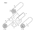
- wire holder 1 and three wires 90 are first prepared as shown in Fig. 4 .
- wires 90 are respectively fit into recesses 41, 51, 61.
- wires 90 are placed therein along axis O, which is the rotation symmetry axis of wire holder 1.
- Each of wires 90 has a circular cross sectional shape, and insulating portion 92 thereof has a circular outer circumferential shape.
- wires 90 are contained in recesses 41, 51, 61 having, as their bottom surfaces, arc portions 42, 52, 62 having the arc shapes in cross section.
- Wires 90 are placed in recesses 41, 51, 61 with the circumferential surfaces of wires 90 respectively facing arc portions 42, 52, 62. In this way, wires 90 can be aligned relative to one another.
- a band-shaped bundling device 99 such as a bundling band made of, for example, a resin is wound around wire holder 1 and the three wires respectively fit into recesses 41, 51, 61, thereby bundling wires 90.
- Bundling device 99 is provided to be wound around the circumference of wire holder 1 in contact with tip portions 14, 24, 34 of three wall portions 11, 21, 31.
- the wire bundling structure of the first embodiment shown in Fig. 6 includes: wire holder 1; three wires 90 fit into recesses 41, 51, 61 of wire holder 1; and band-shaped bundling device 99, provided to be wound around the circumference of wire holder 1 in contact with tip portions 14, 24, 34 of wall portions 11, 21, 31, for bundling wires 90.
- wires 90 are fit into recesses 41, 51, 61 of wire holder 1 and are readily aligned relative to one another. This achieves improved operation efficiency in bundling wires 90, and reduces the number of process steps required in bundling.
- band-shaped bundling device 99 bundles wires 90 in contact with tip portions 14, 24, 34 of wall portion 11, 21, 31, wires 90 can be bundled without damage, as with the conventional wire bundling structure for winding a glass tape around each wire.
- portions thereof to be bundled by bundling device 99 need to be aligned with one another in order to determine where to wind the glass tape. This requires skilled operators for the bundling to obtain a high-quality bundling structure.
- wires 90 can be aligned relative to one another readily by the simplified operation of putting wires 90 into recesses 41, 51, 61 of wire holder 1. Accordingly, irrespective of operators, uniformity in quality of the wire bundling structure can be improved.
- the high-voltage wires can be readily bundled in close proximity to one another, thereby readily reducing the surge voltage.
- the wire bundling structure of the present embodiment can be used more suitably.
- Fig. 7 is a perspective view showing a wire holder of a second embodiment.
- Fig. 8 is a front view of the wire holder shown in Fig. 7 .
- Wire holder 101 of the second embodiment in Fig. 7 and Fig. 8 includes four wall portions 111, 121, 131, 141, and is capable of bundling four wires. In this point, wire holder 101 is different from wire holder 1 of the first embodiment for holding three wires.
- wall portions 111, 121, 131, 141 in the second embodiment are formed rotationally symmetric to one another, are provided to project in a direction orthogonal to an axis O, which serves as a rotation symmetry axis, and extends along axis O.
- axis O which serves as a rotation symmetry axis
- recesses 151, 161, 171, 181 each having an arc shape in cross section, for holding wires.
- Recesses 151, 161, 171, 181 have bottom surfaces formed by arc portions 152, 162, 172, 182 each having an arc shape.
- Each of recesses 151, 161, 171, 181 has a span length L (i.e., a distance of a straight line between opening end portions 153, 154, which are the opposite ends in the arc shape of arc portion 152) equal to or greater than 85% of the diameter of each of the wires.
- Each of recesses 151, 161, 171, 181 is formed to have an arc shape in cross section with an arc angle ⁇ of not less than 150° and not more than 210°, where arc angle ⁇ is an angle formed by two line segments connecting a central point C of the arc shape in recess 161 to opening end portions 163, 164, which are the two ends in arc portion 162.
- Wall portions 111, 121, 131, 141 have a wall thickness t equal to or smaller than 1/2 of a radius r of the arc shape of each of recesses 151, 161, 171, 181, at their portions intersecting with the straight line connecting central points C of the arc shapes of two adjacent ones of recesses 151, 161, 171, 181, such as thin portion 143 of wall portion 141.
- the wires can be readily aligned relative to one another. This eliminates the operation of winding a glass tape around each one of the wires upon bundling the plurality of wires, thereby improving operation efficiency and reducing the number of process steps required in bundling the wires.
- a wire holder and a wire bundling structure of the present invention are advantageously applicable to, in particular, a holder for holding high-voltage wires used in a power converter or the like, as well as a bundling structure thereof
Landscapes
- Engineering & Computer Science (AREA)
- Architecture (AREA)
- Civil Engineering (AREA)
- Structural Engineering (AREA)
- Installation Of Indoor Wiring (AREA)
- Clamps And Clips (AREA)
- Mutual Connection Of Rods And Tubes (AREA)
- Suspension Of Electric Lines Or Cables (AREA)
- Insertion, Bundling And Securing Of Wires For Electric Apparatuses (AREA)
- Supports For Pipes And Cables (AREA)
Abstract
Description
- The present invention relates to a wire holder and a wire bundling structure, in particular, to a holder for high-voltage wires used in a power converter or the like and a bundling structure thereof
- Conventionally, a spacer for inserting and installing a multiplicity of cables in one installed pipe is disclosed in, for example, Japanese Patent Laying-Open No.
2003-284216 - Patent Document 1: Japanese Patent Laying-Open No.
2003-284216 - In a snubber circuit wire of a main thyristor element in a power converter, each wire's inductance, which is one factor of generating a surge voltage, needs to be small in order to suppress the surge voltage. Conventionally, to achieve a small inductance, wires different in directions in which currents flow in the snubber circuit have been bundled to one another.
- In bundling such snubber circuit wires, their coatings need to be prevented from being damaged, so as not to compromise insulating strength for high voltage. In view of this, conventionally, a glass tape is wound around a bundling portion of each of the wires for protection, and these wires are then bundled by a commercially available bundling band. As such, a large number of process steps are required in bundling the wires, with the result that operation efficiency is hardly improved in wiring operations for a power converter, disadvantageously.
- The present invention is made in view of the foregoing problem, and its main object is to provide a wire holder and a wire bundling structure, each of which allows for reduced number of process steps required in bundling wires.
- A wire holder according to the present invention is a wire holder for relative alignment of a plurality of wires upon bundling the wires, and includes a plurality of wall portions. The wall portions are formed rotationally symmetric to one another, provided to project in a direction orthogonal to a rotation symmetry axis, and extend along the rotation symmetry axis. Between opposite ones of the wall portions, recesses having arc shapes in cross section are formed to hold the wires. Each of the recesses has a span length of not less than 85% of a diameter of each of the wires. The wires can be aligned by fitting the wires into the recesses and arranging the wires along the rotation symmetry axis.
- Here, the term "rotational symmetry" indicates types of symmetry characterizing figural objects. A property called "n-fold rotational symmetry", "rotational symmetry of order n", "(360/n) symmetry", or the like is such that when a figural object is rotated around a center (in the case of a two-dimensional figural object) or an axis (in the case of a three-dimensional figural object) by (360/n), the figural object overlaps with itself, where n is an integer equal to or greater than 2. For example, with n = 3, the figural object overlaps with itself when the figural object is rotated by 120°, which means threefold rotational symmetry. The term "rotation symmetry axis" refers to an axis that serves as the center of rotation when a rotationally symmetric three-dimensional figural object is rotated to overlap with itself. Namely, when a figural object is rotated around the rotation symmetry axis by (360/n), the figural object thus rotated coincides with the figural object in its initial location.
- Meanwhile, the term "arc shape in cross section" indicates that when a member is viewed in cross section along a predetermined cross sectional line, the member is formed to have its sectional shape forming a shape of arc. Further, the term "span length" refers to a line segment with a minimum length among line segments formed by trimming lines, which pass through the barycenter of a figural object, with the contour shape of the figural object, such as the length of the diameter of a circle and the length of a side of a square. In the present specification, the length of a line segment connecting the opposite ends of an opening in the cross section of each recess having the arc shape in cross section (i.e., a distance of a straight line between the opposite ends of the arc) is referred to as the span length of the recess.
- In the wire holder, the recesses are formed to have the arc shapes in cross section with an arc angle of not less than 150° and not more than 210°. Here, the term "arc angle" refers to an angle formed by two intersecting line segments that connect the center of the arc and the two end portions of the arc.
- In the wire holder, each of the wall portions has a wall thickness of not more than 1/2 of a radius of each of the arc shapes in the recesses, at its portion intersecting with a straight line connecting centers of the arc shapes of two adjacent ones of the recesses.
- The wire bundling structure according to the present invention includes: the wire holder in any one of the above-described aspects; the plurality of wires fit into the recesses; and a band-shaped bundling device, provided to be wound around the wire holder in contact with tip portions of the plurality of wall portions, for bundling the wires.
- According to the wire holder and the wire bundling structure of the present invention, an operation of winding a glass tape around each one of the wires can be eliminated upon bundling the plurality of wires. Accordingly, the number of process steps required in bundling the wires can be reduced drastically.
-
-
Fig. 1 is a perspective view showing a wire holder of a first embodiment. -
Fig. 2 is a front view of the wire holder shown inFig. 1 . -
Fig. 3 is a side view of the wire holder shown inFig. 1 . -
Fig. 4 is a perspective view showing a first process for bundling wires using the wire holder. -
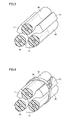
Fig. 5 is a perspective view showing a second process for bundling the wires using the wire holder. -
Fig. 6 is a perspective view showing a third process for bundling the wires using the wire holder. -
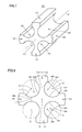
Fig. 7 is a perspective view showing a wire holder of a second embodiment. -
Fig. 8 is a front view of the wire holder shown inFig. 7 . - 1, 101: wire holder; 11, 21, 31, 111, 121, 131, 141: wall portion; 12, 22, 32: thick portion; 13, 23, 33, 143: thin portion; 14, 24, 34: tip portion; 15: base; 41, 51, 61, 151, 161, 171, 181: recess; 42, 52, 62, 152, 162, 172, 182: arc portion; 43, 44, 53, 54, 153, 154, 163, 164: opening end portion; 90: wire; 91: electrically conductive portion; 92: insulating portion; 99: bundling device; C: central point; L: span length; O: axis; r: radius; t: wall thickness; θ: arc angle.
- The following describes embodiments of the present invention, with reference to figures. It should be noted that in the figures described below, the same or corresponding portions are given the same reference characters and are not described repeatedly.
- It should be also noted that in the embodiments described below, each component is not necessarily essential for the present invention unless otherwise noted. In addition, in the embodiments described below, when the number, an amount, and the like are described, they are merely illustrative and the scope of the present invention is not necessarily limited to the number, the amount, and the like, unless otherwise noted.
-
Fig. 1 is a perspective view showing a wire holder of a first embodiment.Fig. 2 is a front view of the wire holder shown inFig. 1 .Fig. 3 is a side view of the wire holder shown inFig. 1 . Specifically,Fig. 2 shows the wire holder when viewed in a direction of arrow II shown inFig. 1 .Fig. 3 shows the wire holder when viewed in a direction of arrow III shown inFig. 1 . Referring toFigs. 1-3 , a configuration ofwire holder 1 according to the first embodiment will be described. - As shown in
Figs. 1-3 ,wire holder 1 has threewall portions Wall portions Wall portions wire holder 1 is viewed in cross section along a cross sectional line orthogonal to axis O, i.e., whenwire holder 1 is viewed in direction DR1 as shown inFig. 2 ,wall portions thick portions thin portions -
Wall portions thick portions tip portions O. Tip portions thick portions thin portions tip portions tip portions wall portions base 15 in the vicinity of axis O.Wall portions thin portions base 15. - Because
wall portions thick portions thin portions recess 41 is formed betweenwall portions recess 51 is formed betweenwall portions recess 61 is formed betweenwall portions wall portions recess 41 formed to be surrounded bythin portions wall portion 11 andwall portion 21.Wall portions recess 51 formed to be surrounded bythin portions wall portion 21 andwall portion 31.Wall portions recess 61 formed to be surrounded bythin portions wall portions 31 andwall portion 11. -
Recesses thin portions wall portions Wall portions thin portions wall portions thin portions recesses wall portions - Now, a feature in the shape of each of
recesses Fig. 2 . As shown inFig. 2 , recesses 41, 51, 61 have bottom surfaces constituted byarc portions Fig. 2 , whenwire holder 1 is viewed in front or whenwire holder 1 is viewed in cross section along the cross sectional line orthogonal to axis O and not shown in the figure, each of the bottom surfaces ofrecesses arc portion 42, openingend portions arc portion 52, openingend portions - The length of a line segment connecting opening
end portions recess 41 having the arc shape in cross section (i.e., a distance in a straight line between openingend portions recess 41. Each ofrecesses wire holder 1. If span length L of each ofrecesses recesses recesses - On the other hand, if span length L of each of
recesses recesses holder 1 upon bundling the wires. In view of this, by setting span length L of each ofrecesses - Further, a point serving as the center of the arc shape of each of
arc portions recess 51 to openingend portions arc portion 52 intersect with each other at central point C to form an angle, which is regarded as an "arc angle θ". Each ofrecesses - If arc angle θ is too small,
arc portions recesses recesses arc portions recesses - Now, a straight line (indicated by a chain double-dashed line in
Fig. 2 ) is considered which connects central points C of the arc shapes ofarc portions recesses wall portion 11. Adjacent to the opposite side surfaces ofwall portion 11, recesses 41, 61 are formed. The straight line connecting respective central points C ofarc portions thin portion 13 ofwall portion 11.Wall portion 11 has a wall thickness t at its portion intersecting with the straight line. Further,arc portion 62 ofrecess 61 is formed to have an arc shape with a radius r.Wall portions - As a distance between the plurality of wires held by
wire holder 1 is smaller, the inductance of each wire can be reduced more. Hence, by setting wall thickness t at 1/2 of radius r or smaller, the inductance thereof can be reduced more effectively. On the other hand, if wall thickness t is too small, it becomes difficult to manufacturewire holder 1 andwire holder 1 is weakened in strength. Hence, the lower limit value for wall thickness t can be determined to be equal to or greater than 1/4 of radius r. - The following describes a method for bundling the plurality of wires using
wire holder 1 configured as above. Each ofFigs. 4-6 is a perspective view showing a process of bundling the wires using the wire holder. Each ofwires 90 to be bundled is a coated wire, in which an insulatingportion 92 having an annular shape in cross section is provided to cover the circumference of an elongated electricallyconductive portion 91. Electricallyconductive portion 91 is formed of a material having a high electric conductivity, such as a metal. Insulatingportion 92 is formed of an insulating material such as a resin. Insulatingportion 92 coats the circumference of electricallyconductive portion 91. -
Wire holder 1 of the first embodiment includes threewall portions recesses wires 90 is formed between two adjacent wall portions across the opposing surfaces of the two adjacent wall portions. Using such awire holder 1, threewires 90 can be relatively aligned and can be bundled. - To bundle such three wires using
wire holder 1,wire holder 1 and threewires 90 are first prepared as shown inFig. 4 . Next, as shown inFig. 5 ,wires 90 are respectively fit intorecesses wires 90 are placed therein along axis O, which is the rotation symmetry axis ofwire holder 1. Each ofwires 90 has a circular cross sectional shape, and insulatingportion 92 thereof has a circular outer circumferential shape. Hence,wires 90 are contained inrecesses arc portions Wires 90 are placed inrecesses wires 90 respectively facingarc portions wires 90 can be aligned relative to one another. - Next, as shown in
Fig. 6 , a band-shapedbundling device 99 such as a bundling band made of, for example, a resin is wound aroundwire holder 1 and the three wires respectively fit intorecesses wires 90. Bundlingdevice 99 is provided to be wound around the circumference ofwire holder 1 in contact withtip portions wall portions wires 90 usingbundling device 99,wires 90 are fixed to wireholder 1, thereby obtaining a wire bundling structure shown inFig. 6 . - The wire bundling structure of the first embodiment shown in
Fig. 6 includes:wire holder 1; threewires 90 fit intorecesses wire holder 1; and band-shapedbundling device 99, provided to be wound around the circumference ofwire holder 1 in contact withtip portions wall portions wires 90. According to this wire bundling structure,wires 90 are fit intorecesses wire holder 1 and are readily aligned relative to one another. This achieves improved operation efficiency in bundlingwires 90, and reduces the number of process steps required in bundling. - Because band-shaped
bundling device 99bundles wires 90 in contact withtip portions wall portion wires 90 can be bundled without damage, as with the conventional wire bundling structure for winding a glass tape around each wire. In the case of winding the glass tape around each wire, portions thereof to be bundled by bundlingdevice 99 need to be aligned with one another in order to determine where to wind the glass tape. This requires skilled operators for the bundling to obtain a high-quality bundling structure. In contrast, in the wire bundling structure of the present embodiment,wires 90 can be aligned relative to one another readily by the simplified operation of puttingwires 90 intorecesses wire holder 1. Accordingly, irrespective of operators, uniformity in quality of the wire bundling structure can be improved. - Particularly important in the case of applying a voltage not less than 1 kV is reduction of the inductance of each wire to suppress a surge voltage. In particular, when applying a voltage of approximately 3 kV, corona may be generated, so it is essential to reduce the inductance of each wire. By bundling high-voltage wires using the wire bundling structure of the first embodiment, the high-voltage wires can be readily bundled in close proximity to one another, thereby readily reducing the surge voltage. Specifically, when
wires 90 to be bundled are high-voltage wires to be fed with a voltage of not less than 1 kV, the wire bundling structure of the present embodiment can be used more suitably. -
Fig. 7 is a perspective view showing a wire holder of a second embodiment.Fig. 8 is a front view of the wire holder shown inFig. 7 .Wire holder 101 of the second embodiment inFig. 7 and Fig. 8 includes fourwall portions wire holder 101 is different fromwire holder 1 of the first embodiment for holding three wires. - As with the first embodiment,
wall portions wall portions recesses Recesses arc portions - Each of
recesses end portions recesses recess 161 to openingend portions arc portion 162. -
Wall portions recesses recesses thin portion 143 ofwall portion 141. - By fitting a plurality of wires into
recesses wire holder 101 of the second embodiment and arranging them along axis O upon bundling the plurality of wires, the wires can be readily aligned relative to one another. This eliminates the operation of winding a glass tape around each one of the wires upon bundling the plurality of wires, thereby improving operation efficiency and reducing the number of process steps required in bundling the wires. - Although the embodiments of the present invention have been described, it should be considered that the embodiments disclosed herein are illustrative and non-restrictive in any respect. The scope of the present invention is defined by the scope of claims, and is intended to include any modifications within the scope and meaning equivalent to the terms of the claims.
- A wire holder and a wire bundling structure of the present invention are advantageously applicable to, in particular, a holder for holding high-voltage wires used in a power converter or the like, as well as a bundling structure thereof
Claims (4)
- A wire holder (1) for relative alignment of a plurality of wires (90) upon bundling said wires (90), comprising a plurality of wall portions (11, 21, 31) formed rotationally symmetric to one another, provided to project in a direction orthogonal to a rotation symmetry axis, and extending along said rotation symmetry axis,
between opposite ones of said wall portions (11, 21, 31), recesses (41, 51, 61) having arc shapes in cross section being formed to hold said wires (90),
each of said recesses (41, 51, 61) having a span length of not less than 85% of a diameter of each of said wires,
said wires (90) being able to be aligned by fitting said wires (90) into said recesses (41, 51, 61) and arranging said wires (90) along said rotation symmetry axis. - The wire holder (1) according to claim 1, wherein said recesses (41, 51, 61) are formed to have the arc shapes in cross section with an arc angle of not less than 150° and not more than 210°.
- The wire holder (1) according to claim 1, wherein each of said wall portions (11, 21, 31) has a wall thickness of not more than 1/2 of a radius of each of the arc shapes in said recesses (41, 51, 61), at its portion intersecting with a straight line connecting centers of the arc shapes of two adjacent ones of said recesses (41, 51, 61).
- A wire bundling structure comprising:the wire holder (1) recited in any one of claims 1-3;the plurality of wires (90) fit into said recesses (41, 51, 61); anda band-shaped bundling device (99), provided to be wound around the wire holder (1) in contact with tip portions (14, 24, 34) of the plurality of wall portions (11, 21, 31), for bundling said wires (90).
Applications Claiming Priority (1)
| Application Number | Priority Date | Filing Date | Title |
|---|---|---|---|
| PCT/JP2008/067726 WO2010038269A1 (en) | 2008-09-30 | 2008-09-30 | Wire holder and wire bundling structure |
Publications (3)
| Publication Number | Publication Date |
|---|---|
| EP2330705A1 true EP2330705A1 (en) | 2011-06-08 |
| EP2330705A4 EP2330705A4 (en) | 2012-10-31 |
| EP2330705B1 EP2330705B1 (en) | 2013-10-30 |
Family
ID=42073064
Family Applications (1)
| Application Number | Title | Priority Date | Filing Date |
|---|---|---|---|
| EP08877133.2A Active EP2330705B1 (en) | 2008-09-30 | 2008-09-30 | Wire holder and wire bundling structure |
Country Status (6)
| Country | Link |
|---|---|
| US (1) | US20110147543A1 (en) |
| EP (1) | EP2330705B1 (en) |
| JP (1) | JP5122652B2 (en) |
| CN (1) | CN102165660B (en) |
| ES (1) | ES2443121T3 (en) |
| WO (1) | WO2010038269A1 (en) |
Families Citing this family (14)
| Publication number | Priority date | Publication date | Assignee | Title |
|---|---|---|---|---|
| US20120285740A1 (en) * | 2011-05-10 | 2012-11-15 | Tyco Electronics Corporation | Cable assembly |
| JP5729205B2 (en) * | 2011-08-05 | 2015-06-03 | 住友電装株式会社 | Electric wire holder |
| CN103090109A (en) * | 2011-10-27 | 2013-05-08 | 泛达公司 | Separating device of harness |
| WO2016114495A1 (en) * | 2015-01-16 | 2016-07-21 | 엘에스전선 주식회사 | Umbilical cable for deep sea |
| CA2964648A1 (en) * | 2016-04-19 | 2017-10-19 | STM Venture Partners Inc. | Multi-line conduit assemblies |
| JP6719277B2 (en) * | 2016-05-25 | 2020-07-08 | 株式会社豊田中央研究所 | Unit frame, vehicle frame |
| JP7052430B2 (en) * | 2018-03-06 | 2022-04-12 | トヨタ自動車株式会社 | String-shaped binding tool |
| JP6580204B1 (en) * | 2018-05-21 | 2019-09-25 | 三菱電機株式会社 | Brush motor |
| WO2020074960A1 (en) | 2018-10-11 | 2020-04-16 | Nvent Services Gmbh | Device and methods for armoring heat shrink kits for impact and flammability protection |
| EP3865707A1 (en) | 2020-02-13 | 2021-08-18 | Siemens Gamesa Renewable Energy A/S | Self-clamping cable guard for clamping power cables of a power cable bundle of a cable support arrangement in a wind turbine, cable support arrangement and wind turbine |
| US11859743B2 (en) * | 2021-10-15 | 2024-01-02 | General Electric Company | System for spacing and fastening tubular structures |
| US11898682B2 (en) * | 2021-10-15 | 2024-02-13 | General Electric Company | System for spacing and fastening tubular structures |
| CN218603081U (en) * | 2022-10-24 | 2023-03-10 | 秦山电缆集团有限公司 | Cable fixing band |
| CN115680883A (en) * | 2022-10-27 | 2023-02-03 | 中国航发沈阳黎明航空发动机有限责任公司 | An aero-engine three-pipe clamp |
Family Cites Families (12)
| Publication number | Priority date | Publication date | Assignee | Title |
|---|---|---|---|---|
| US3092360A (en) * | 1962-02-08 | 1963-06-04 | Boeing Co | Positive locking fairlead for electrical cables |
| JPS519929B1 (en) * | 1967-05-04 | 1976-03-31 | ||
| US5027478A (en) * | 1986-01-31 | 1991-07-02 | Suhr Robert N | Coiling clamp for linear flexible material |
| JPH0253588U (en) * | 1988-10-11 | 1990-04-18 | ||
| JP2545075Y2 (en) * | 1991-05-24 | 1997-08-25 | 日本大洋海底電線株式会社 | Cable laying spacer |
| US5742982A (en) * | 1996-11-25 | 1998-04-28 | Siecor Corporation | Cable strain relief apparatus |
| JP2001327053A (en) * | 2000-05-19 | 2001-11-22 | Kajima Corp | Cable support |
| US20030173470A1 (en) * | 2002-03-12 | 2003-09-18 | Geiger Gerard G. | Conduit Isolator Mount |
| JP2003284216A (en) | 2002-03-25 | 2003-10-03 | Nikkai Ns Kk | Multiple cable installation spacer |
| JP2004048972A (en) * | 2002-05-23 | 2004-02-12 | Reichle & De Massari Ag | Method for preventing crosstalk in communication cable and crosstalk preventing member and tool for communication cable |
| US6710249B1 (en) * | 2002-09-13 | 2004-03-23 | Sandra L. Denton | Wire separator |
| JP4422451B2 (en) * | 2003-08-27 | 2010-02-24 | 鉄志 吉田 | Concentrating holder for wire rods at the work site |
-
2008
- 2008-09-30 ES ES08877133.2T patent/ES2443121T3/en active Active
- 2008-09-30 CN CN2008801314155A patent/CN102165660B/en active Active
- 2008-09-30 JP JP2010531665A patent/JP5122652B2/en active Active
- 2008-09-30 EP EP08877133.2A patent/EP2330705B1/en active Active
- 2008-09-30 US US13/060,613 patent/US20110147543A1/en not_active Abandoned
- 2008-09-30 WO PCT/JP2008/067726 patent/WO2010038269A1/en not_active Ceased
Also Published As
| Publication number | Publication date |
|---|---|
| CN102165660A (en) | 2011-08-24 |
| JP5122652B2 (en) | 2013-01-16 |
| CN102165660B (en) | 2013-12-11 |
| JPWO2010038269A1 (en) | 2012-02-23 |
| EP2330705B1 (en) | 2013-10-30 |
| US20110147543A1 (en) | 2011-06-23 |
| WO2010038269A1 (en) | 2010-04-08 |
| EP2330705A4 (en) | 2012-10-31 |
| ES2443121T3 (en) | 2014-02-17 |
Similar Documents
| Publication | Publication Date | Title |
|---|---|---|
| US20110147543A1 (en) | Wire holder and wire bundling structure | |
| JP5945155B2 (en) | Connection structure of external conductor terminal of electric wire | |
| US20120279776A1 (en) | Shield conducting path | |
| US20150364977A1 (en) | Stator, stator manufacturing method, and rotary electric machine | |
| JP6281448B2 (en) | Conductive path | |
| US9522640B2 (en) | Wire harness and shield conductive path | |
| KR20130118973A (en) | Stator for rotating electric machine | |
| US20210111603A1 (en) | Wire bonding device of stator of motor | |
| US10176906B2 (en) | Shielded conductive path | |
| CN103875128B (en) | Suitable for the electric connector for the cable for receiving various diameters | |
| EP2683044A1 (en) | Protective implement, method of manufacturing same, and shielded conductor | |
| JP5811946B2 (en) | Wire harness | |
| US10381818B2 (en) | Covering processing tool and covering processing method | |
| US10784019B2 (en) | Cable | |
| JP6823941B2 (en) | Cable branch structure and coating treatment tool | |
| US20220189655A1 (en) | Wire harness | |
| JP5382858B2 (en) | Fixing method for wire cover and insulation cover | |
| JP2013055771A (en) | Ground wire lead-out part and power cable connection part | |
| JP2013037805A (en) | Insulation electric wire and wire harness | |
| JP2017216102A (en) | Conductive connecting member | |
| JP2015015832A (en) | Exterior protective structure of wire harness | |
| US10188093B2 (en) | Active electrostatic wildlife guard for electrical power distribution equipment | |
| JP2016006741A (en) | Water stopping structure for insulation-coated wire and wire harness | |
| JP2002157926A (en) | Twisted pair cable | |
| CN108975082A (en) | Coil device applied to cable |
Legal Events
| Date | Code | Title | Description |
|---|---|---|---|
| PUAI | Public reference made under article 153(3) epc to a published international application that has entered the european phase |
Free format text: ORIGINAL CODE: 0009012 |
|
| 17P | Request for examination filed |
Effective date: 20110223 |
|
| AK | Designated contracting states |
Kind code of ref document: A1 Designated state(s): AT BE BG CH CY CZ DE DK EE ES FI FR GB GR HR HU IE IS IT LI LT LU LV MC MT NL NO PL PT RO SE SI SK TR |
|
| AX | Request for extension of the european patent |
Extension state: AL BA MK RS |
|
| DAX | Request for extension of the european patent (deleted) | ||
| A4 | Supplementary search report drawn up and despatched |
Effective date: 20121001 |
|
| RIC1 | Information provided on ipc code assigned before grant |
Ipc: H02G 3/30 20060101AFI20120925BHEP Ipc: H02G 1/06 20060101ALI20120925BHEP |
|
| REG | Reference to a national code |
Ref country code: DE Ref legal event code: R079 Ref document number: 602008028473 Country of ref document: DE Free format text: PREVIOUS MAIN CLASS: H02G0003300000 Ipc: H02G0015007000 |
|
| RIC1 | Information provided on ipc code assigned before grant |
Ipc: H02G 3/30 20060101ALI20130411BHEP Ipc: H02G 15/076 20060101ALI20130411BHEP Ipc: H02G 15/013 20060101ALI20130411BHEP Ipc: H02G 15/007 20060101AFI20130411BHEP Ipc: H02G 15/117 20060101ALI20130411BHEP |
|
| GRAP | Despatch of communication of intention to grant a patent |
Free format text: ORIGINAL CODE: EPIDOSNIGR1 |
|
| INTG | Intention to grant announced |
Effective date: 20130603 |
|
| GRAS | Grant fee paid |
Free format text: ORIGINAL CODE: EPIDOSNIGR3 |
|
| GRAA | (expected) grant |
Free format text: ORIGINAL CODE: 0009210 |
|
| AK | Designated contracting states |
Kind code of ref document: B1 Designated state(s): AT BE BG CH CY CZ DE DK EE ES FI FR GB GR HR HU IE IS IT LI LT LU LV MC MT NL NO PL PT RO SE SI SK TR |
|
| REG | Reference to a national code |
Ref country code: GB Ref legal event code: FG4D |
|
| REG | Reference to a national code |
Ref country code: CH Ref legal event code: EP |
|
| REG | Reference to a national code |
Ref country code: AT Ref legal event code: REF Ref document number: 638719 Country of ref document: AT Kind code of ref document: T Effective date: 20131115 |
|
| REG | Reference to a national code |
Ref country code: IE Ref legal event code: FG4D |
|
| REG | Reference to a national code |
Ref country code: DE Ref legal event code: R096 Ref document number: 602008028473 Country of ref document: DE Effective date: 20131224 |
|
| REG | Reference to a national code |
Ref country code: NL Ref legal event code: T3 |
|
| REG | Reference to a national code |
Ref country code: ES Ref legal event code: FG2A Ref document number: 2443121 Country of ref document: ES Kind code of ref document: T3 Effective date: 20140217 |
|
| REG | Reference to a national code |
Ref country code: AT Ref legal event code: MK05 Ref document number: 638719 Country of ref document: AT Kind code of ref document: T Effective date: 20131030 |
|
| REG | Reference to a national code |
Ref country code: LT Ref legal event code: MG4D |
|
| PG25 | Lapsed in a contracting state [announced via postgrant information from national office to epo] |
Ref country code: NO Free format text: LAPSE BECAUSE OF FAILURE TO SUBMIT A TRANSLATION OF THE DESCRIPTION OR TO PAY THE FEE WITHIN THE PRESCRIBED TIME-LIMIT Effective date: 20140130 Ref country code: IS Free format text: LAPSE BECAUSE OF FAILURE TO SUBMIT A TRANSLATION OF THE DESCRIPTION OR TO PAY THE FEE WITHIN THE PRESCRIBED TIME-LIMIT Effective date: 20140228 Ref country code: SE Free format text: LAPSE BECAUSE OF FAILURE TO SUBMIT A TRANSLATION OF THE DESCRIPTION OR TO PAY THE FEE WITHIN THE PRESCRIBED TIME-LIMIT Effective date: 20131030 Ref country code: HR Free format text: LAPSE BECAUSE OF FAILURE TO SUBMIT A TRANSLATION OF THE DESCRIPTION OR TO PAY THE FEE WITHIN THE PRESCRIBED TIME-LIMIT Effective date: 20131030 Ref country code: BE Free format text: LAPSE BECAUSE OF FAILURE TO SUBMIT A TRANSLATION OF THE DESCRIPTION OR TO PAY THE FEE WITHIN THE PRESCRIBED TIME-LIMIT Effective date: 20131030 Ref country code: LT Free format text: LAPSE BECAUSE OF FAILURE TO SUBMIT A TRANSLATION OF THE DESCRIPTION OR TO PAY THE FEE WITHIN THE PRESCRIBED TIME-LIMIT Effective date: 20131030 Ref country code: FI Free format text: LAPSE BECAUSE OF FAILURE TO SUBMIT A TRANSLATION OF THE DESCRIPTION OR TO PAY THE FEE WITHIN THE PRESCRIBED TIME-LIMIT Effective date: 20131030 |
|
| PG25 | Lapsed in a contracting state [announced via postgrant information from national office to epo] |
Ref country code: LV Free format text: LAPSE BECAUSE OF FAILURE TO SUBMIT A TRANSLATION OF THE DESCRIPTION OR TO PAY THE FEE WITHIN THE PRESCRIBED TIME-LIMIT Effective date: 20131030 Ref country code: AT Free format text: LAPSE BECAUSE OF FAILURE TO SUBMIT A TRANSLATION OF THE DESCRIPTION OR TO PAY THE FEE WITHIN THE PRESCRIBED TIME-LIMIT Effective date: 20131030 Ref country code: CY Free format text: LAPSE BECAUSE OF FAILURE TO SUBMIT A TRANSLATION OF THE DESCRIPTION OR TO PAY THE FEE WITHIN THE PRESCRIBED TIME-LIMIT Effective date: 20131030 |
|
| PG25 | Lapsed in a contracting state [announced via postgrant information from national office to epo] |
Ref country code: PT Free format text: LAPSE BECAUSE OF FAILURE TO SUBMIT A TRANSLATION OF THE DESCRIPTION OR TO PAY THE FEE WITHIN THE PRESCRIBED TIME-LIMIT Effective date: 20140228 |
|
| PG25 | Lapsed in a contracting state [announced via postgrant information from national office to epo] |
Ref country code: EE Free format text: LAPSE BECAUSE OF FAILURE TO SUBMIT A TRANSLATION OF THE DESCRIPTION OR TO PAY THE FEE WITHIN THE PRESCRIBED TIME-LIMIT Effective date: 20131030 |
|
| REG | Reference to a national code |
Ref country code: DE Ref legal event code: R097 Ref document number: 602008028473 Country of ref document: DE |
|
| PG25 | Lapsed in a contracting state [announced via postgrant information from national office to epo] |
Ref country code: SK Free format text: LAPSE BECAUSE OF FAILURE TO SUBMIT A TRANSLATION OF THE DESCRIPTION OR TO PAY THE FEE WITHIN THE PRESCRIBED TIME-LIMIT Effective date: 20131030 Ref country code: PL Free format text: LAPSE BECAUSE OF FAILURE TO SUBMIT A TRANSLATION OF THE DESCRIPTION OR TO PAY THE FEE WITHIN THE PRESCRIBED TIME-LIMIT Effective date: 20131030 Ref country code: RO Free format text: LAPSE BECAUSE OF FAILURE TO SUBMIT A TRANSLATION OF THE DESCRIPTION OR TO PAY THE FEE WITHIN THE PRESCRIBED TIME-LIMIT Effective date: 20131030 Ref country code: CZ Free format text: LAPSE BECAUSE OF FAILURE TO SUBMIT A TRANSLATION OF THE DESCRIPTION OR TO PAY THE FEE WITHIN THE PRESCRIBED TIME-LIMIT Effective date: 20131030 Ref country code: IT Free format text: LAPSE BECAUSE OF FAILURE TO SUBMIT A TRANSLATION OF THE DESCRIPTION OR TO PAY THE FEE WITHIN THE PRESCRIBED TIME-LIMIT Effective date: 20131030 |
|
| PLBE | No opposition filed within time limit |
Free format text: ORIGINAL CODE: 0009261 |
|
| STAA | Information on the status of an ep patent application or granted ep patent |
Free format text: STATUS: NO OPPOSITION FILED WITHIN TIME LIMIT |
|
| PG25 | Lapsed in a contracting state [announced via postgrant information from national office to epo] |
Ref country code: DK Free format text: LAPSE BECAUSE OF FAILURE TO SUBMIT A TRANSLATION OF THE DESCRIPTION OR TO PAY THE FEE WITHIN THE PRESCRIBED TIME-LIMIT Effective date: 20131030 |
|
| 26N | No opposition filed |
Effective date: 20140731 |
|
| REG | Reference to a national code |
Ref country code: DE Ref legal event code: R097 Ref document number: 602008028473 Country of ref document: DE Effective date: 20140731 |
|
| PG25 | Lapsed in a contracting state [announced via postgrant information from national office to epo] |
Ref country code: SI Free format text: LAPSE BECAUSE OF FAILURE TO SUBMIT A TRANSLATION OF THE DESCRIPTION OR TO PAY THE FEE WITHIN THE PRESCRIBED TIME-LIMIT Effective date: 20131030 |
|
| REG | Reference to a national code |
Ref country code: DE Ref legal event code: R119 Ref document number: 602008028473 Country of ref document: DE |
|
| PG25 | Lapsed in a contracting state [announced via postgrant information from national office to epo] |
Ref country code: MC Free format text: LAPSE BECAUSE OF FAILURE TO SUBMIT A TRANSLATION OF THE DESCRIPTION OR TO PAY THE FEE WITHIN THE PRESCRIBED TIME-LIMIT Effective date: 20131030 Ref country code: LU Free format text: LAPSE BECAUSE OF FAILURE TO SUBMIT A TRANSLATION OF THE DESCRIPTION OR TO PAY THE FEE WITHIN THE PRESCRIBED TIME-LIMIT Effective date: 20140930 |
|
| REG | Reference to a national code |
Ref country code: CH Ref legal event code: PL |
|
| GBPC | Gb: european patent ceased through non-payment of renewal fee |
Effective date: 20140930 |
|
| REG | Reference to a national code |
Ref country code: DE Ref legal event code: R119 Ref document number: 602008028473 Country of ref document: DE Effective date: 20150401 |
|
| REG | Reference to a national code |
Ref country code: FR Ref legal event code: ST Effective date: 20150529 |
|
| PG25 | Lapsed in a contracting state [announced via postgrant information from national office to epo] |
Ref country code: GB Free format text: LAPSE BECAUSE OF NON-PAYMENT OF DUE FEES Effective date: 20140930 Ref country code: CH Free format text: LAPSE BECAUSE OF NON-PAYMENT OF DUE FEES Effective date: 20140930 Ref country code: LI Free format text: LAPSE BECAUSE OF NON-PAYMENT OF DUE FEES Effective date: 20140930 Ref country code: DE Free format text: LAPSE BECAUSE OF NON-PAYMENT OF DUE FEES Effective date: 20150401 |
|
| PG25 | Lapsed in a contracting state [announced via postgrant information from national office to epo] |
Ref country code: FR Free format text: LAPSE BECAUSE OF NON-PAYMENT OF DUE FEES Effective date: 20140930 |
|
| PG25 | Lapsed in a contracting state [announced via postgrant information from national office to epo] |
Ref country code: BG Free format text: LAPSE BECAUSE OF FAILURE TO SUBMIT A TRANSLATION OF THE DESCRIPTION OR TO PAY THE FEE WITHIN THE PRESCRIBED TIME-LIMIT Effective date: 20131030 |
|
| PG25 | Lapsed in a contracting state [announced via postgrant information from national office to epo] |
Ref country code: GR Free format text: LAPSE BECAUSE OF FAILURE TO SUBMIT A TRANSLATION OF THE DESCRIPTION OR TO PAY THE FEE WITHIN THE PRESCRIBED TIME-LIMIT Effective date: 20140131 Ref country code: MT Free format text: LAPSE BECAUSE OF FAILURE TO SUBMIT A TRANSLATION OF THE DESCRIPTION OR TO PAY THE FEE WITHIN THE PRESCRIBED TIME-LIMIT Effective date: 20131030 |
|
| PG25 | Lapsed in a contracting state [announced via postgrant information from national office to epo] |
Ref country code: HU Free format text: LAPSE BECAUSE OF FAILURE TO SUBMIT A TRANSLATION OF THE DESCRIPTION OR TO PAY THE FEE WITHIN THE PRESCRIBED TIME-LIMIT; INVALID AB INITIO Effective date: 20080930 |
|
| PGFP | Annual fee paid to national office [announced via postgrant information from national office to epo] |
Ref country code: TR Payment date: 20240919 Year of fee payment: 17 |
|
| PGFP | Annual fee paid to national office [announced via postgrant information from national office to epo] |
Ref country code: NL Payment date: 20250814 Year of fee payment: 18 |
|
| PGFP | Annual fee paid to national office [announced via postgrant information from national office to epo] |
Ref country code: IE Payment date: 20250812 Year of fee payment: 18 |
|
| PGFP | Annual fee paid to national office [announced via postgrant information from national office to epo] |
Ref country code: ES Payment date: 20251013 Year of fee payment: 18 |